1
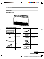
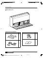
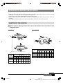
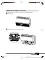
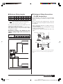
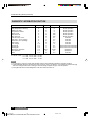
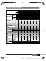
Installation Manual
MINISPLIT
FLOOR/CEILING
AIR CONDITIONER
MODELS
MCC-MCH/MOC-MOH 09
MCC-MCH/MOC-MOH 12
MCC-MCH/MOC-MOH 18
MCC-MCH/MOC-MOH 25
MCC-MCH/MOC-MOH 35
MCC-MCH/MOC-MOH 45
MCC-MCH/MOC-MOH 55
035T80012-000
01_install.p65
1
19/4/02, 14:41
CONTENTS
Safety Precautions ...................................... 4
Cautions for Installation ........................................... 4
Part List ......................................................... 5
Indoor Unit ............................................................ 5-6
Preparation Before Installation .................. 7
Selection of the Location ......................................... 7
Drilling Measurement ............................................... 8
Remote Control Receiving Type Setting ............ 9-10
Installation in the Following Places
May Result in Trouble ............................................ 11
Installation Diagram .................................. 12
Please read this installation manual
carefully before starting the installation.
It will tell you necessary information.
Installation Procedure ............................... 13
Indoor Unit ........................................................ 13-14
Outdoor Unit ..................................................... 15-17
Test Operation ............................................ 18
Check This Item Before Start Operation ................ 18
System Test Diagnostics ........................................ 18
Trouble Shooting Guide ............................ 19
Diagnostic Information Function ............................ 20
Technical Specification ............................. 21
Indoor Unit .............................................................. 21
Condensing Unit ............................................... 22-23
Quality POLICY
We will continuously strive to satisfy
our customers with consistent reliability
in product, service and support.
2
02_install.p65
FLOOR/CEILING
2
YORK MINISPLIT FLOOR/CEILING Code 035T80012-000
19/4/02, 14:45
REQUIRED TOOLS
EXTENDED PARTS
1. Refrigerant Pipe
1. Screw Driver
2. Hexagonal Wrench
MCC-MCH/MOC-MOH
Models
3. Torque Wrench
9
12
18,25,35
45,55
4. Spanner
Liquid size
1/4"
1/4"
3/8"
3/8"
5. Reamer
Gas size
3/8"
1/2"
5/8"
3/4"
6. Hole Core Drill
8. Thermometer
2. Pipe Insulation Material (Polyethylene foam
9 mm thick)
9. Manifold Guage
3. Vinyl Tape
10. Gas Leak Detector
4. Putty
7. Tape Measure
11. Vacuum Pump
12. Pipe Clamp
13. Pipe Cutter
14. Flare Tool Set
15. Electrical Circuit Tester
FLOOR/CEILING
02_install.p65
3
3
19/4/02, 14:45
YORK MINISPLIT FLOOR/CEILING Code 035T80012-000
SAFETY PRECAUTIONS
• Please read this installation manual carefully before starting installation of the unit.
• This air conditioning system contains refrigerant under pressure, rotating parts and
electrical connection which may be dangerous and can cause injury. Installation
and maintenance of this air conditioning system should only be carried out by trained
and qualified personnel.
• After unpacking, please check the unit carefully for possible damage.
• Before undertaking any work on the unit, make sure that the power supply has
been disconnected.
CAUTIONS FOR INSTALLATION
Do not store or unpack the unit in a wet area or expose
to rain or water.
Do not install in a place where flammable gas may
leak.
It may cause fire.
It may cause the unit to short circuit and may result electric
shocks or fire.
This system is designed for domestic or residential
use only.
Do not conduct installation in wet area or in the rain.
It is a high risk to cause the electrical shocks.
4
02_install.p65
If used in certain envionments, such as a manufacturing
workplace, the equipment may not function efficiently.
FLOOR/CEILING
4
YORK MINISPLIT FLOOR/CEILING Code 035T80012-000
19/4/02, 14:45
PART LIST
INDOOR UNIT
■ MCC-MCH 09-25
INSTALLATION ACCESSORIES
Description
Q'ty
USE
Description
Q'ty
USE
Drain Hose
Cover Plate
2
1
Insulation (Drain hose)
Tapping Screw (∅4x10)
Adhesive type
2
1
Tapping Screw (∅4x20)
6
For indoor side pipe
joint (small pipe)
VT Wire
1
Wall Bracket
Bracket for wall
installation
For drain hose
(280 mm)
Remote Control
2
TEMP
SLEEP
ON/OFF
Coupler Heat Insulator
1
For indoor side pipe
joint
Installation and
Owner’s manual
2
Installation
Manual
Nylon Fastener
Owner's Ma
nual
2
For drain hose
1
(continued)
FLOOR/CEILING
02_install.p65
5
5
19/4/02, 14:45
YORK MINISPLIT FLOOR/CEILING Code 035T80012-000
Part list (continued)
N
1
2
■ MCC-MCH 35-55
INSTALLATION ACCESSORIES
Description
Q'ty
Description
Q'ty
Remote Control
Bracket
TEMP
SLEEP
2
1
ON/OFF
Installation and Owner’s manual
Rubber, Screw and Bolt
Installation
Manual
Owner's Ma
16
6
02_install.p65
FLOOR/CEILING
6
YORK MINISPLIT FLOOR/CEILING Code 035T80012-000
19/4/02, 14:45
nual
2
PREPARATION BEFORE INSTALLATION
• Before doing any work, check the interior power supply cord and the main breaker capacity are sufficient and the
installation area is sufficient and complies with the requirements.
• Check that the power supply available agrees with nameplate voltage.
• Electrical work, wiring and cables must be performed in compliance with national and local wiring codes and
standard.
• Do not use the extension cables. In the case extended cables are needed, use the terminal block.
SELECTION OF THE LOCATION
■ Select a place which provides the space around the units as shown in the
diagram below.
Outdoor Unit
Indoor Unit
Dimension
(cm)
12
MCC-MCH
18
25
35
09
45
55
A
50
50
50
50
50
50
50
B
80
80
80
80
80
80
80
C
5
5
5
5
5
5
5
D
20
20
20
20
20
20
20
Dimension
(cm)
09
12
MOC-MOH
18
25
35
45
55
A
40
40
40
40
40
40
40
B
20
20
20
20
20
20
20
C
20
20
20
20
20
20
20
D
60
60
60
60
60
60
60
(continued)
FLOOR/CEILING
02_install.p65
7
7
19/4/02, 14:45
YORK MINISPLIT FLOOR/CEILING Code 035T80012-000
Preparation Before Installation (continued)
DRILLING MEASUREMENT
■ Indoor Unit
Model MCC-MCH 35, 45, 55
Drain hose drilling measurment floor case.
6
15
Drill the hole to fixing unit follow the diagram
below
A
325
Ceiling Installation Drilling
177
31
G
77.5
130
C
175
A
15
110
25
B
86
Dimensions
(mm)
35
MCC-MCH
45
G
1,122
55
1,122
1,442
■ Outdoor Unit
133.5
D
133.5
230
268
248
E
497
F
MO 09-12
Dimensions
(mm)
35
MCC-MCH
45
A
B
C
D
E
1,402
201
145
215
115
1,402
201
145
215
115
1,692
201
145
215
115
F
88
88
88
517
144
144
260
316
296
55
MO 18
429
287
315
234
Floor Installation Drilling
Drain hose drilling measurment floor case.
100
24
Model MCC-MCH 09, 12, 18, 25
100
150
550
150
990mm
MO 25
245mm
511mm
100
42mm
8
02_install.p65
60
160
95mm
95mm
740
MO 35-55
FLOOR/CEILING
8
YORK MINISPLIT FLOOR/CEILING Code 035T80012-000
10
30
30
19/4/02, 14:45
160
395
375
125mm
10
245mm
335
64
24
64
REMOTE CONTROL RECEIVING TYPE SETTING
The Indoor Unit can set its remote control receiver into type-A and type-B.
1
Open front grille.
2
Adjust dip switch 1 No. 8 to desire receiver type.
(continued)
FLOOR/CEILING
02_install.p65
9
9
19/4/02, 14:45
YORK MINISPLIT FLOOR/CEILING Code 035T80012-000
Preparation Before Installation (continued)
Switch
No.
SW1
8
Setting
H
L
Remote Control receive
A
B
Notes
1.
2.
3.
4.
Default remote control receiving type setting is type-A.
Default remote control transmission type setting is type-A.
Remote control receiving type must be correct to Remote control transmission type.
Setting Remote control Transmission type see the Owner’s manual.
10 FLOOR/CEILING
02_install.p65
10
YORK MINISPLIT FLOOR/CEILING Code 035T80012-000
19/4/02, 14:45
INSTALLATION IN THE FOLLOWING PLACES MAY RESULT IN TROUBLE
Installation in the unit in wrong direction.
Installation of the indoor unit in direct sun light.
Installation of the indoor unit in a place where there
is an obstacle near the air inlet or outlet.
> 30 cm
Installation of outdoor units too close or, blowing
discharged air into each other.
Installation of the outdoor unit in a place exposed
regularly to a strong wind.
Installation of the indoor unit at too high > 30 cm a
position.
FLOOR/CEILING
02_install.p65
11
11
19/4/02, 14:45
YORK MINISPLIT FLOOR/CEILING Code 035T80012-000
INSTALLATION DIAGRAM
Indoor Unit
Bracket
Front Grille
Indoor Unit
Outdoor Unit
Connecting
Cable
Front Grille
Wall Bracket
Refrigerant Piping
Refrigerant Piping
Additional Drain Hose
12 FLOOR/CEILING
03_install.p65
12
YORK MINISPLIT FLOOR/CEILING Code 035T80012-000
19/4/02, 14:48
INSTALLATION PROCEDURE
Cautions
• Piping must be performed by qualified personnel according to good refrigeration system practices
• Piping materials and insulation materials must be refrigerant quality
• Select the pipe diamerters according to the size of unit and cut the pipe to design length by pipe cutter
• Check that no foreign bodies are inside the pipe
• Connect the pipe correctly
• Do not apply the excessive torque
• Connect the electric cable correctly
• Use an appropriate bending tool to form curves and avoid over-tightening the refrigerant tubes
INDOOR UNIT
Bracket Fixing
Drain Hose Drilling
1
Measure and mark the hole position.
1
2
Drill a hole and mount bracket.
2
Measure and mark the hole position.
Drill a hole at a slight downward slant toward
the outdoor side.
Ceiling drain hose hole
Floor drain hose hole
Wall Bracket Fixing
1
Measure amd mark the hole position.
2
Drill a hole and mount bracket.
Note : When installing the
refrigerant pipes from
others side. A hole must
be place to allow fall
towards the outdoor unit.
.. .
... ...
... ..... ..
.. .
... ...... ..
.
.
.
... ...... ..
.. .
... ...... ..
. .
Indoor
.. .
... ...
... ..... ..
.. .
... ...... ..
.
.. .. ......
... ...
... ..... ..
.
... ....
Outdoor
5
(continued)
FLOOR/CEILING
03_install.p65
13
13
19/4/02, 14:48
YORK MINISPLIT FLOOR/CEILING Code 035T80012-000
Installation Procedure (continued)
■ Indoor Unit Fixing
After fixing the indoor unit, open front grille and then
insert refrigerant pipe, drain hose and electric cable from
outdoor through the wall into the unit case, then connect
drain hose together and arrange it.
Ceiling Case
1
Lift the indoor unit to the bracket.
2
Push the indoor unit to lock at the bracket.
Floor Case
1
2
3
Tighten the bolt to lock indoor unit to
bracket floor case.
Lift the indoor unit, and hang it to the wall
bracket.
Make sure that the unit is correctly hung in
place by sliding it to the left and the to the
right.
Note : Do not put the drain hose end into water.
Verification of condensate water drainage:
Fill the drain pan with water and observe evacuation.
■ Unit Coupling
■ Drain Hose
1
Connect electric cable to terminal box.
2
Connect refrigerant pipe to flare connector.
Drain hose can pass through the indoor unit
follow figure below.
Terminal box
2
Flare connector
N
1
Ceiling case
Floor case
14 FLOOR/CEILING
03_install.p65
14
YORK MINISPLIT FLOOR/CEILING Code 035T80012-000
19/4/02, 14:48
OUTDOOR UNIT
■ Unit Fixing
1
MCH/MOH 09-25 Heat pump Units
1
2
3
Indoor
Unit
N
1
2
3
Outdoor
Unit
Measure and mark the hole position.
L
2
N
Drill the hole and fix the outdoor unit.
Power Supply
220-240V/1Ph/50Hz
208-230V/1Ph/60Hz
MCH/MOH 25 Heat pump Units
N
L1 L2 L3
Indoor
Unit
1
2
3
N
1
2
3
Outdoor Unit
Power Supply
380-415V/3Ph/50Hz
MCC/MOC 35 Cooling Units
L
N
1
2
Indoor
Unit
N
1
2
Outdoor
Unit
Power Supply
220-240V/1Ph/50Hz
208-230V/1Ph/60Hz
■ Unit Coupling
Connect electric cable to terminal box follow
electric diagrame below.
MCC/MOC 35-55 Cooling Units
N
MCC/MOC 09-25 Cooling Only Units
N
L
1
N
1
2
Indoor
Unit
2
Outdoor
Unit
L1
L2
L3
1
N
Indoor
Unit
2
1
2
Outdoor
Unit
Power Supply
Power Supply
220-240V/1Ph/50Hz
208-230V/1Ph/60Hz
380-415V/3Ph/50Hz
460V/3Ph/60Hz
MCH/MOH 35 Heat pump Units
MCC/MOC 25 Cooling Units
N
1
2
Indoor
Unit
L
L1
L2
L3
Power Supply
N
1
2
Outdoor
Unit
N
1
2
3
Indoor
Unit
N
1
2
3
Outdoor
Unit
Power Supply
220-240V/1Ph/50Hz
208-230V/1Ph/60Hz
380-415V/3Ph/50Hz
(continued)
FLOOR/CEILING
03_install.p65
15
15
19/4/02, 14:48
YORK MINISPLIT FLOOR/CEILING Code 035T80012-000
Installation Procedure (continued)
■ Wiring Sizes
MCH/MOH 35-55 Heat pump Units
N
1
2
3
Indoor
Unit
Unit size
Power supply
L1 L2 L3
N
2
1
3
Outdoor Unit
Power Supply
380-415V/3Ph/50Hz
460V/3Ph/60hz
9 12 18 25
mm2
Interconnection Cooling mm2
(Indoor/Outdoor) Heating mm2
Fuse (slow-Blow)
A
35
45 55
3x2.5 3x4 5x2.5 5x4
3x2.5 + Ground
4x2.5 + Ground
10
16 20 10
16
Or as required to meet national and local codes.
Notes
• Terminals N and 1 (see diagrams above) correspond
to power supply to the indoor unit coming from the
outdoor unit.
• Compressor power supply is established by teminal 2.
• Power supply to the 4-way valve is established by
terminal 3.
• For further details on wiring of these units, see the
diagrams pasted inside each unit.
L N 1
2
For further detail on wiring of these units, see the diagrams
pasted inside each unit.
Cautions
• Never modify the unit by removing any of the safety
guards or by bypassing any of the safety interlock
swithces.
• Connect the connecting cable correctly and connect
the connecting cable to terminal as identified with their
respective marks.
• Do not scratch the conductive core & inner insulator of
power supply cables and do not deform or smash on
the surface of cables.
16 FLOOR/CEILING
03_install.p65
16
YORK MINISPLIT FLOOR/CEILING Code 035T80012-000
19/4/02, 14:48
■ Maximum Piping Lengths
Unit size
D (m)
L (m)
H (m)
9
12
15
10
12
15
18
12
18
15
18
12
25
22
25
20
35
20
25
22
45
24
30
26
55
20
30
26
■ Refrigerant Piping Connections
(FLARE Connections)
To avoid alteration of unit capacities, check that piping
lengths and changes in elevation are kept to a strict
minimum.
Note : Where the difference in elevation between the
indoor unit and the outdoor unit is greater than 5
meters, install an oil trap every 5 meters.
Before connectiong the refrigerant lines, follow the
procedures below (if pre-charged connection lines are
not supplied):
The suction line must have a 2% gradient up to the
compressor on horizontal sections.
Where piping lengths are unusually long and include a
large number of oil traps, it may be necessary to adjust
to compressor charge.
- Select copper pipe diameters according to the size of
unit to be installed.
- Install the refrigeration lines, checking that no foreign
bodies get inside the piping.
- Install the flare connectors and flare the ends of the
pipes.
Refrigerant charge to be added per extra
metre of piping length when more than 7.5
meters.
Unit size
g/m
Manifold
MCC-MCH/MOC-MOH
12
18
25
35
45
15
40
40
40
40
9
15
Low Pressure High Pressure
55
40
POWER
TIMER
COMP
EMERGENCY SWITCH
Liquid Valve
Pressure Tap
Outdoor Unit
Gas Line
Gas Valve
Indoor Unit
Liquid Line
L
R407C
D
This unit is shipped complete with a charge of R407C refrigerant
that will be sufficient for an interconnecting piping length of 5
meters.
L
H
POWER
TIMER
COMP
EMERGENCY SWITCH
FLOOR/CEILING
03_install.p65
17
17
30/5/02, 2:29 pm
YORK MINISPLIT FLOOR/CEILING Code 035T80012-000
TEST OPERATION
CHECK THIS ITEM BEFORE START OPERATION
Outdoor
• Check the flare nut connections, valve stem cap connections and service cap connections for gas leak with a leak
detector or soap water.
Indoor
•
•
•
•
•
Check the unit is firmly fixed.
Check the connecting pipes are tighten securely.
Check the pipe insulation.
Check the drainage.
Check the connection of the grounding wire.
SYSTEM TEST DIAGNOSTICS
Test Operation Mode
1) This is a diagnostic mode to check the functioning of a unit. In installations with multiple units it is possible to start
the Test Operation Mode in all the units sequenially and run the test mode in parallel, thus shortening the time for
service calls. By consulting the status of each unit a diagnosis can be made of any problems or normal operation
can be verified.
2) Test Operation mode carries out the following operational sequence and then returns to the normal mode after
the Test operation is finished. In the case of Cool only systems the sequence will be completed after STEP 2. If a
problem is encountered during Test Operation mode the unit will indicate this as shown in the chart below and the
LED Display will flash according to the LED Diagnostic Codes. If an error occurs the reset shall be when the EMS
switch is pressed for more than 1 second and less than 10 seconds. Upon release, the operation shall return to
normal and the unit shall be off.
3) To start this mode, the emergency switch must be pressed for at least 10 seconds and released while in normal
operation mode. To interrupt this mode, press the emergency switch again for at least 10 seconds.
4) If a failure occurs during the test mode operation the unit the board shall:- Stop the operating of compressor
- Indicate the error by the lamp out puts
- Remain in that condition until reset
Test Operation Mode
In cool only mode
Input
STEP 1
STEP 2
Fan only high
Cool mode : fan high
Cool mode : fan med
Cool mode : fan low
Stop Waiting
Heating mode : fan high
Heating mode : fan med
Heating mode : fan low
Waiting
STEP 3
STEP 4
STEP 5
Operation time
Minutes
3
4
Diagnostic
2
3
3
4
Diagnostic
2
3
3
Any timer settings entered before the start of the Test Operation Mode will not be affected by the Test Operation Mode.
Failure display follows the conditions below.
Status
Operation
Low HP temp < 20˚C
fan stop and louver full open
Coil temp > 40˚C (cooling) fan stop and louver full open
Overheat > 62˚C (heating) louver full open
Anti Freeze
louver full open
Low voltage
halt
Sensor fail
stop
Cooling fail
stop
Heating fail
stop
Terminating Condition
Coil temp 20˚C
Coil temp 40˚C
Coil temp 50˚C
Coil temp 5˚C
return to normal range
system reset
system reset
system reset
18 FLOOR/CEILING
03_install.p65
18
YORK MINISPLIT FLOOR/CEILING Code 035T80012-000
19/4/02, 14:48
TROUBLE SHOOTING GUIDE
Probable cause
Problem
A.The air conditioner does not
run.
Remedy
1. Power Failure.
2. Fuse blown or circuit breaker
open.
3. Voltage is too low.
4. Faulty contactor or relay.
5. Electrical connections loose.
6. Thermostat adjustment too low
(in heating mode) or too high (in
cooling mode).
7. Faulty Capacitor.
8. Incorrect wiring, terminal loose.
9. Pressure switch tripped.
B.The outdoor fan runs but the
compressor will not start.
1. Motor winding cut or grounded.
2. Faulty Capacitor.
C.There is insufficient heating or
cooling.
1. There is a gas leak.
2. Liquid and gas line insulated
together.
3. The room was probably very hot
(cool) when you started the
system.
D.The compressor run
continuously.
E. The compressor starts but
shuts down quickly.
7. Find the cause then replace
Capacitor.
8. Check and retighten.
9. Find the cause before reset.
1. Check the wiring and the
compressor winding resistance.
2. Find the cause then replace
Capacitor.
1. Remove charge, repair, evacuate
and recharge.
2. Insulate them separately.
3. Wait while unit has enough time to
cool the room.
1. Thermostat adjustment too low
(in heating mode) or too high (in
cooling mode).
2. Faulty fan.
3. Refrigerant charge too low, leak.
4. Air or incondensables in
refrigerant circuit.
1. Check Thermostat setting.
1. Too much or too little refrigerant.
1. Remove charge, evacuate and
recharge.
2. Determine the cause and replace
compressor.
3. Remove charge, evacuate and
recharge.
4. Replace it.
2. Faulty compressor.
F. Clicking sound is heard from
the air conditioner.
1. Wait for Power resume.
2. Replace the fuse or reset the
breaker.
3. Find the cause and fix it.
4. Replace the faulty component.
5. Retighten the connection.
6. Check Thermostat setting.
3. Air or incondensables in
refrigerant circuit.
4. Changeover valve damaged or
blocked open (heat pump unit)
In heating or cooling operation any
plastic parts may expand or shrink
due to a sudden temperatue change
in this event, a clicking sound may
occur.
2. Check condenser air circulation.
3. Find leak, repair and recharge.
4. Remove charge, evacuate and
recharge.
In heating or cooling operation any
plastic parts may expand or shrink due
to a sudden temperatue change in this
event, a clicking sound may occur.
(continued)
FLOOR/CEILING
03_install.p65
19
19
19/4/02, 14:48
YORK MINISPLIT FLOOR/CEILING Code 035T80012-000
Trouble Shooting Guide (continued)
DIAGNOSTIC INFORMATION FUNCTION
Status
OFF(with power on)
ON (Temperature satisfied)
Waiting for delay
Compressor started
Sleep mode
Start timer set
Stop timer set
Low HP temp < 20°C
Coil temp > 40°C (cooling)
Overheat > 62°C (heating)
Anti Freeze
Low voltage
Sensor fail
Cooling fail
Heating fail
Emergency operation
Test operation
Filter
Power
Timer
Operation
Mode
O
X
X
X
X
X
X
X
X
X
X
F-2
F-1
F-2
F-3
F-3
F-1
F-3
O
O
F-1
O
X
F-2
F-3
O
O
F-1
F-2
O
O
O
O
Note 1
F-1
F-3
O
O
O
X
X/O
X/O
X/O
F-1
F-2
F-1
F-2
O
F-1
F-2
F-3
Note 1
F-1
F-3
Normal Operation
Normal Operation
Normal Operation
Normal Operation
Normal Operation
Normal Operation
Normal Operation
Protection
Protection
Protection
Protection
Protection
Reset-Call Service Technician
Reset-Call Service Technician
Reset-Call Service Technician
Operational
Operational
Protection
X = ON, O = OFF, F-1 = ON : 0.5 sec, OFF : 0.5 sec
F-2 = ON : 1.5 sec, OFF : 0.5 sec
F-3 = ON : 0.5 sec, OFF : 1.5 sec
Notes
1) In emergency mode, the Power light will flash and the other lights will indicate the operation as above.
2) Lights will flash during the time that the units is held off, due to Low Voltage. If the voltage has passed through
the reset voltage and the unit is waiting for the time delay, the lights will go to normal operation.
3) The lights will show the LED Diagnostic Code even when the unit is off.
20 FLOOR/CEILING
03_install.p65
20
YORK MINISPLIT FLOOR/CEILING Code 035T80012-000
19/4/02, 14:48
TECHNICAL SPECIFICATION
Indoor
Unit
Models
MCC-MCH
09
12
18
09
12
18
25
35
45
55
10,200
14,700
19,800
28,000
42,000
50,000
kW
2.2
3.0
4.3
5.8
8.2
12.3
14.7
kcal/h
1,849
2,576
3,700
4,990
7,056
10,584
12,600
Btu/h
7,500
10,200
14,700
19,800
28,000
42,000
50,000
kW
2.2
3.0
4.3
5.8
8.2
12.3
14.7
kcal/h
1,849
2,576
3,700
4,990
7,056
10,584
12,600
V/Ph/Hz
Power Consumption
Running Current
220-240/1/50 or 380-415/3/50
Ph
1
1
1
1
3
3
3
kW
0.973
1.344
1.839
2.743
3.666
5.102
5.372
A
4.48
6.33
8.42
12.8
7.91
11.44
13.88
Refrigerat Type
R-407C
Fan
Indoor Unit
220-240/1/50
V/Ph/Hz
Power Supply
Ph
1
1
1
1
1
1
1
3
m /h
490
580
700
820
1,270
1,550
2,455
W
36
47
69
85
177
234
204
Height
mm
655
655
655
655
658
658
658
Width
mm
990
990
990
990
1,548
1,548
1,845
Depth
mm
199
199
199
199
205
205
240
kg
26
26
27
29
46.5
46.5
62
Air Flow
Input Power
Weight
System Operation Control
Weigth
Piping
Outdoor Unit
Dimension
Wired or Wireless Control with LCD Display
Qty
1
1
Compressor Type
1
1
1
Rotary
1
1
Scroll
Height
mm
492
492
590
696
900
1,142
1,142
Width
mm
764
764
820
850
1,060
1,060
1,060
Depth
Cooling
mm
230
230
280
287
345
345
345
38
42
62
68
107
127
127
40
43
63
69
109
129
129
Heating
kg
Type
Pipe Size
55
7,500
Heating
Compressor
45
Btu/h
Nominal Capacitie
Dimension
35
Outdoor
Unit
Cooling
Power Supply
25
MOC-MOH
Flare and Nuts
Suction
inch
3/8"
1/2"
5/8"
5/8"
5/8"
3/4"
3/4"
Liquid
inch
1/4"
1/4"
3/8"
3/8"
3/8"
3/8"
3/8"
(continued)
FLOOR/CEILING
03_install.p65
21
21
20/4/02, 09:37
YORK MINISPLIT FLOOR/CEILING Code 035T80012-000
TECHNICAL SPECIFICATION
Indoor
Unit
Models
MCC-MCH
09
12
18
09
12
18
25
35
45
55
10,200
14,700
19,800
28,000
42,000
50,000
kW
2.2
3.0
4.3
5.8
8.2
12.3
14.7
kcal/h
1,849
2,576
3,700
4,990
7,056
10,584
12,600
Btu/h
7,500
10,200
14,700
19,800
28,000
42,000
50,000
kW
2.2
3.0
4.3
5.8
8.2
12.3
14.7
kcal/h
1,849
2,576
3,700
4,990
7,056
10,584
12,600
V/Ph/Hz
Power Consumption
Running Current
220-240/1/50 or 380-415/3/50
Ph
1
1
1
1
3
3
3
kW
0.973
1.344
1.839
2.743
3.666
5.102
5.372
A
4.48
6.33
8.42
12.8
7.91
11.44
13.88
Refrigerat Type
R-407C
Fan
Indoor Unit
220-240/1/50
V/Ph/Hz
Power Supply
Ph
1
1
1
1
1
1
1
3
m /h
490
580
700
820
1,270
1,550
2,455
W
36
47
69
85
177
234
204
Height
mm
655
655
655
655
658
658
658
Width
mm
990
990
990
990
1,548
1,548
1,845
Depth
mm
199
199
199
199
205
205
240
kg
26
26
27
29
46.5
46.5
62
Air Flow
Input Power
Weight
System Operation Control
Wired or Wireless Control with LCD Display
Qty
1
1
Compressor Type
1
1
1
1
Scroll
mm
492
492
590
696
900
1,142
1,142
Width
mm
764
764
820
850
1,060
1,060
1,060
Depth
mm
230
230
280
287
345
345
345
kg
40
42
64
Type
Pipe Size
1
Rotary
Height
Weigth
Piping
Outdoor Unit
Dimension
55
7,500
Heating
Compressor
45
Btu/h
Nominal Capacitie
Dimension
35
Outdoor
Unit
Cooling
Power Supply
25
MOC-MOH
68
Flare and Nuts
Suction
inch
3/8"
1/2"
5/8"
5/8"
5/8"
3/4"
3/4"
Liquid
inch
1/4"
1/4"
3/8"
3/8"
3/8"
3/8"
3/8"
(continued)
FLOOR/CEILING
03_install.p65
21
21
19/4/02, 14:48
YORK MINISPLIT FLOOR/CEILING Code 035T80012-000
––––––––/––––––––––––/––––––––
03_install.p65
22
19/4/02, 14:48
––––––––/––––––––––––/––––––––
03_install.p65
23
19/4/02, 14:48
DE - COMMISSIONING DISMANTLING & DISPOSAL
This product contains refrigerant under pressure, rotating parts, and electrical connections which may be a
danger and cause injury!
All work must only be carried out by competent persons using suitable protective clothing and safety precautions.
Read the Manual
Risk of electric shock
Unit is remotely controlled and
may start without warning
1. Isolate all sources of electrical supply to the unit including any control system supplies switched by the unit. Ensure
that all points of electrical and gas isolation are secured in the OFF position. The supply cables and gas pipework may
then be disconnected and removed. For points of connection refer to unit installation instructions.
2. Remove all refrigerant from each system of the unit into a suitable container using a refrigerant reclaim or recovery unit.
This refrigerant may then be re-used, if appropriate, or returned to the manufacturer for disposal. Under No
circumstances should refrigerant be vented to atmosphere. Where appropriate, drain the refrigerant oil from each
system into a suitable container and dispose of according to local laws and regulations governing disposal of oily
wastes.
3. Packaged unit can generally be removed in one piece after disconnection as above. Any fixing down bolts should be
removed and then unit lifted from position using the points provided and equipment of adequate lifting capacity.
Reference MUST be made to the unit installation instructions for unit weight and correct methods of lifting. Note that
any residual or spilt refrigerant oil should be mopped up and disposed of as described above.
4. After removal from position the unit parts may be disposed of according to local laws and regulations.
YORK® International Corporation
24 FLOOR/CEILING
03_install.p65
24
YORK MINISPLIT FLOOR/CEILING Code 035T80012-000
19/4/02, 14:48