1
Voyager IP
User guide
Specifications
Ethernet Connection
Serial Port
Concurrent Users
Data Encryption
TCP Ports
USB Port
Operating Systems
Resolution
Video and mouse
synchronization
Security
One – RJ 45 - 10/100 Mbit/sec auto-sensing.
One – RJ 45
1 user + 7 view Only for current session
128bit SSL
443, 900, 901, 902.
Ports 900-902 are configurable from port number 800 upwards
One – Reserved for future use.
Target Server
Windows, Dos, LINUX, UNIX, QNX, SGI, FreeBSD, BeOS, Open VMS,
Novell 3.12 and later, Alpha UNIX, HP UX, SUN, Solaris, Java Desktop
System
Client Computer
Windows 2000 or higher with IE 6.0 or higher and ActiveX
Target Server
Up to 1600 x 1200 @ 85Hz
Client Computer
Recommended - resolution should be higher than the Target Server
Both auto and manual modes
128-bit SSL encryption
NOTE: This equipment complies with the requirements of European EMC directive 89/336 EEC in
respect of EN55022 Class B, EN 50082-1 and EN 60555-2.
This equipment has been found to comply with the limits for a Class A digital device, pursuant to
Part 15 of the FCC Rules. These limits are designed to provide reasonable protection against
harmful interference when the equipment is operated in a commercial environment. This equipment
generates, uses, and can radiate radio frequency energy and, if not installed and used in
accordance with the instruction manual, may cause harmful interference to radio communications.
Operation of this equipment in a residential area is likely to cause harmful interference in which
case the user will be required to correct the interference at his own expense.
© Copyright 2006. All rights reserved.
Daxten, the Daxten logo, Voyager and The Brains Behind KVM Switching and Sharing are trademarks of Daxten Industries.
All other trademarks acknowledged.
Revision 1.0
Voyager IP
2
User Guide
Voyager IP
Introduction
The Voyager IP is a device that enables you to control your server over TCP/IP via LAN, WAN or
Internet connection, from any location.
Product Features
Bios level KVM control.
- Control any server irrespective of the server status or network connectivity.
Web based control.
- Web browser control of target server, from any location via standard secured IP
connection.
Multi user view mode.
- Allows multiple users to simultaneous view a remote session. Remote control
between users with appropriate permissions.
Client Computer Requirements
The client computer requires Windows 2000 or later, with Internet Explorer 6.0 or later, 128bit
encryption support for a secured connection.
Default IP Address
The Voyager IP boots with DHCP enabled, it looks for IP address from a DHCP server on the network.
If no DHCP server is found, the Voyager IP is configured with a static IP address of 192.168.0.155
Note: if a DHCP server becomes available later, the Voyager will pick up it‟s settings
from the DHCP Server. To keep the static IP Address, disable DHCP as explained on
page 4
You can identify the Voyager‟s IP address through the MAC address (see Label on the bottom of the
Voyager IP.
Logging On
Complete the initial setup via the web interface.
Open your Web browser.
Enter the Voyager‟s system IP address. (e.g. https://192.168.0.155/config) and press enter,
the login page will appear.
Enter the Administrator user name and password.
The network configuration page opens.
Note: the default Administrator User Name is admin the default password is admin
(both are lower case)
Voyager IP
3
User Guide
SSL Certificate notes
When you first connect to the Voyager IP unit‟s https configuration page, you will receive 2 browser
security warnings. To proceed you will need to click Yes.
The first warning will disappear when the first client installs the Daxten [Voyager IP] root certificate.
The second warning can be avoided by adding a line to your window‟s „hosts‟ file (normally found at
\Windows\system32\drivers\etc)
The line format should be: any-IP any-name.daxten.kvmip
Example:
192.168.0.155
VoyagerIP. daxten.kvmip
You can now browse the Voyager IP by typing https://VoyagerIP.daxten.kvmip
You can use any device name except for daxten.kvmip which is reserved by Daxten.
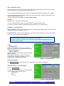
Network – Configuration
Device Name – Enter a name for the Voyager IP. The default Device Name takes the form of a six
digit device number (D.N) prefixed with “D”.
First TCP Port – Select 3 consecutive ports, enter the first port number of the series. The default
port is 900, this should suit most installations.
Note: Your firewall or router security access list must enable inbound communication
through the selected TCP ports for the Voyager IP‟s IP address.
For Client computer access from a secured LAN, the selected ports should be open for
outbound communication.
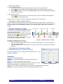
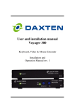
LAN 1
Enable DHCP
When a DHCP server is active on the network to
which the Voyager IP is connected, DHCP provides
automatic IP assignment.
DHCP disabled
(Recommended) You can assign a fixed IP address
to the Voyager IP
When DHCP is disabled, enter the IP Address,
Subnet Mask, and Default Gateway for LAN 1, as
provided by your Network Administrator.
Figure 1 – LAN 1 Settings
Saving Changes
Click Save & Restart to save changes to the configuration, and restart the Voyager IP.
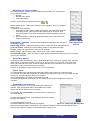
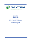
Administration – User Settings
Click on User Settings
On this page, the Administrator can create and edit
users. There are three levels of users: Administrator
User
View only
Figure 2 – User Settings
Voyager IP
4
User Guide
Administrator
An Administrator has unrestricted access to all the Voyager‟s settings and windows. An Administrator
can create and edit users and their passwords. An administrator can also “take over” a remote active
session.
User
A User can access and control target services. A User does not have access to the configuration
pages, advanced mouse settings and power cycling.
View Only
A View Only user can only view target server screens, without keyboard and mouse control. Only
limited options are available to a View Only user such as Switch and Disconnect from servers.
Adding a User
Click on Add and then enter the users name and password. The password has to at least 6 characters
letters or numbers and cannot include the User name as part of the password.
Depending on the security level chosen the user name and password parameters are different. See
section Password Policy on page 6.
Select the permission type from the permissions box.
Click Apply, and the User will appear in the User list.
Editing a User
Click on Edit this allows you change all of the User settings for a user.
Click Apply to save the changes.
Deleting a User
Select a User from the User list click on Delete.
Click Apply to save the changes.
Blocking a User
An alternative to deleting a User, is to Block a user, this keeps the user settings, but blocks a User
from accessing the system. Use the tick box to block and unblock user access.
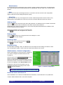
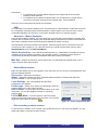
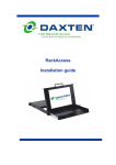
Administration - Switch Configuration
When a KVM Switch is connected to the Voyager IP,
you need to configure the KVM switch from the
Voyager IP.
From the menu click Switch Configuration, the KVM
Switch configuration window appears.
Select the manufacturer of the KVM Switch and the
KVM Switch model. The number of possible servers
to connect to appears in the Server Name section.
Change the name of the connected servers by
highlighting the server and typing a name. Click
Apply to save the changes.
Figure 3 – Switch Configuration
Note: Server names left as UNUSED cannot be accessed.
Install the Switch definition file
If the KVM Switch is not listed in the Manufacturer & Model list, contact Daxten for an updated list.
Load the Switch definition file on the client computer.
Voyager IP
5
User Guide
Locate and install the Switch Definition file, this will update the Manufacturer & Model list.
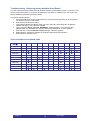
Administration - Serial Settings
If Serial Devices are to be connected to the Voyager
IP Units, the serial settings need to be configured.
From the menu click Serial Settings, the Serial
Settings window appears
Enter a name for the Serial device, and select the
correct parameters for the device.
Show
Tick Show to make the Serial device appear in the
Server/Devices List.
Figure 4 – Security Settings
Security Settings
From the Security section click on Settings to access the security window, from here you can
configure the security settings such as Account Blocking, Password Policy and Idle Timeout.
Account Blocking -This lets you configure the number of login attempts with an incorrect
username or password, after which there is a time bar or total lock
Password Policy - Allows you to select standard password policy or a High security password
policy.
Standard Security Password
6 Characters or more
Must not include the User Name
High Security Password
8 Characters or more,
must include at least
1 numeric
1 upper case letter
1 “special” character as follows
!@#$%^&*()_-+={[}]”’:;?/><
Must not include the User Name
Tick / un-tick the tick box for the High Security Password policy Settings.
Idle Time out - Allows you select the period of inactivity after which a user is disconnected from the
system. Select No Timeout to disable this option.
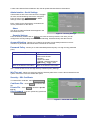
Security – SSL Certificate
To install a SSL certificate, select SSL Certificate.
Certificate File – Click Browse to locate the cer
file.
Private File – Click Browse to locate the private
key file.
Key Password - Type the “private key” password.
Click Save & Restart
Figure 5 – Install SSL Certificate
Voyager IP
6
User Guide
Maintenance – Firmware Upgrade
An upgrade of the Voyager IP will introduce new
features. Firmware upgrades will be available for
download from the Daxten website. Save the
firmware file on the Client computer.
Select Firmware Upgrade.
Click Browse to locate the firmware upgrade file.
Click Start Upgrade, when complete click Reboot,
this will reboot the unit and after 30 seconds the
Login page will appear.
Figure 6 – Firmware Upgrade
Note! Some firmware upgrades may erase User Settings, KVM Switch Settings, mouse
and video adjustments and RS232 setting.
Refer to the firmware release note for more information.
Restore Factory Settings
The Voyager IP can be restored to its factory
settings. This erases all the Voyager IP settings,
including Network settings*, Servers, Switches,
Users, Passwords etc.
* There is an option to save the Network Settings.
Warning!
Once reset the data cannot be retrieved.
Select Restore Factory Settings, the restore factory
setting page shown above appears.
Tick the tick box if you want to preserve the network
settings. Click Restore
Figure 7 – Restore factory settings
Logging Out
To exit the configuration menu, and close the session, click Logout
There can only be one Administrator logged into the configuration page at one time. There is a idle
time out of 30 minutes, after which the session will terminate.
Starting a remote session
On a client computer, start Internet Explorer (version
6.0 and higher) type the Voyager IP‟s IP address
(https://192.168.0.155 default). Enter your username
and password on the login page.
The screen of the Target Server connected directly to
the Voyager IP or the currently selected server on the
KVM Switch connected to the Voyager IP appears.
The first time you connect you must install the Daxten
Certificate and Active X control. You must be logged
on as an administrator on the client computer to
install the Active X Control. Once the Active X control
is installed all user types can login.
Voyager IP
7
Figure 8 – Remote session window
User Guide
Full screen mode
To work in full screen mode:
1. Ensure that the client computer has the same resolution as the Target Server.
2. Press F11, Internet Explorer window disappears leaving the Explorer toolbar at the top.
3. Right click the Explorer toolbar and check Auto-Hide, the Explorer toolbar disappears leaving
you in full screen mode.
To Exit full screen mode:
1. Press F11, or move the mouse cursor at the top of the screen to display Internet Explorer‟s
toolbar and then click restore button.
Note: Full Screen mode can also be activated from the toolbar menu, see page 11.
Taking over a busy remote session
When connecting to a busy Target Server, an Administrator has the option to take over the current
session. A User only has this option if another User is using the current session. A User does not have
the option to take over an Administrators session. You have the option to Take Over, View Only or
Cancel.
Moving or hiding the Toolbar
The toolbar can be dragged and dropped anywhere
on the screen, by clicking and dragging the logo.
To hide the Toolbar, either:
Double click the Voyager IP‟s system tray icon .
Alternatively, press F9 to display the toolbar and
repeat the steps above. See also page 11.
To minimize the Toolbar click the arrow. Click the
arrow again to maximize the Toolbar.
Disconnect
Hide
Keyboard
Mouse
Video
Power
Devices
Performance
Menu
Figure 9 – Remote session Toolbar
Switching to a different server / device
To connect to a different server or device:
1. From the Toolbar click the Device List icon, or right click the Menu icon. A list of connected
servers / devices appears.
2. Click the desired server or Serial Device, the screen of the server or the Serial device window
appears.
Changing the performance settings
The bandwidth settings can be altered from the toolbar.
To alter the settings, from the Toolbar click the Performance icon. The
settings box appears.
Bandwidth
Chose from the following options
Adaptive – automatically adapts to the best compression and
colours.
Low - Use for high compression and 16 colours
Medium – Use for medium compression and 256 colours, this is the
Figure 10 – Settings Box.
recommended setting for a standard internet connection.
High – For low compression and high colours (16 bit), recommended setting for a LAN.
Custom – allows you to choose your own compression and colour level.
Voyager IP
8
User Guide
Adjusting the Video settings
To change the video settings, from the Toolbar click the Video icon. This will give
you the following options:
Refresh
Manual Video Adjust
Auto Video Adjust
Refresh – Refreshes the Video image (Press Ctrl + R ).
Manual Video Adjust – Used to fine tuning the video settings or for a non standard
Video signal.
To adjust the video manually:
1. Click Manual Video Adjust, a slider bar appears, and a Red frame appears
around the screen. This represents the screen area of the server at its
current resolution. Perform the adjustments‟ inside and relative to the red
frame.
2. Move the sliders to change the displayed image. Click in the area of the
sliders for fine tuning.
Figure 11 – Manual
Video Adjustments
the displayed image.
controls.
Horizontal Offset - defines the starting position of each line on the displayed image.
Vertical Offset - defines the vertical starting position of the displayed image.
Phase - defines the point at which each pixel is sampled.
Noise Level - represents the Video "noise" when a static screen is displayed.
Automated adjust – When checked, the video adjusts automatically whenever there is a change
in the screen resolution.
Brightness / Contrast - use the scales to adjust the brightness and contrast of
Auto Video Adjust
To Adjust the video automatically, open a Windows Explorer (or similar) in the background, click Auto
Video Adjust. The process will take a few seconds. If the process runs more than three times, then
there is an abnormal noise level. Check the video cable and ensure that there is no dynamic video
application running on the Target Server‟s desktop.
Perform as necessary for each Target server or screen resolution.
Power Cycle
The optional KB-Power and KB-Power IPMI offer remote power control via a remote session.
To shut down and restart the Target Server via KB-Power / KB-Power IPMI, from the toolbar click the
Power icon. A prompt appears, click Yes to continue.
Only an administrator can initiate a hard reset command.
The Power Management Console can be accessed when the Power Management Console is
activated.
Keyboard key sequences
Click the Keyboard icon. A list of defined keyboard sequences
appears, when clicked these will be transmitted to the Target
Server and will not affect the client computer.
For example, select Ctrl-Alt-Del to send this three key sequence to
the Target Server.
To add a keyboard sequence, Click Add/Remove, the Special Key
Manager box appears.
To add a predefined sequence:
Figure 12 – Special key Manager Box.
Click Add Predefined, a list of sequences appears.
.
Select the desired sequence and click OK. The sequence appears in the Special Key Manager
Box.
Click OK, the sequence appears in the Keyboard Key sequence list.
Voyager IP
9
User Guide
To record a Key sequence:
1. From the Special Key Manager Box press Record Now, the Add Special Key box appears.
2. Give the key sequence a name in the label box.
3. Click Start Recording.
4. Press the desired keys, the keys appear in the area provided.
5. Click Stop Recording.
6. Click OK.
To edit a key sequence
1. From the Special Key Manager Box select the desired key.
2. Click Edit.
3. Click Start Recording.
4. Press the desired keys, the keys appear in the area provided.
5. Click Stop Recording.
6. Click OK.
Synchronising mouse pointers
On a client computer, two mouse pointers appear. The Client computer‟s mouse pointer on top of the
Target Servers. The two mouse pointers should be synchronised. The following explains what to do if
they are not synchronised.
Note: Before synchronising mouse pointers adjust the video of the Target Server
otherwise mouse synchronisation may not work.
Aligning the mice pointers
The two mice pointers may appear a apart from each other, to align the mouse pointers from the
toolbar click the Mouse icon and then Align or press Ctrl M to align the mice pointers.
Calibrating mice pointers
A Target Server may have different mouse pointer speed
The Client computer and Target Server may have different mouse pointer speed settings. Calibrating
will automatically discover the mouse speed of the Target Server and aligns the two pointers.
To calibrate a Windows 2000, NT4 or 98 Target Server :
From the Toolbar click the Mouse icon and then Calibrate. The Voyager IP saves this alignment so
calibration is only required once per Target Server.
If the Video Noise Level is higher than zero, calibration may not work. Use the Video Adjustments to
eliminate the noise.
Note: If the mouse settings on the Target Server are changed, you will need to
synchronise the mouse pointers manually.
Manual mouse synchronisation
To calibrate a Windows XP, 2003, Linux, Novell, SCO Unix or SUN
Target Server, or if the mouse settings on the Target Server are
changed, the mouse pointers must be synchronised manually.
1. From the Toolbar click the Mouse icon and then Manual
Settings.
2. Select the Target Server‟s operating System and click OK.
Instructions and sliders appear.
3. Follow the instructions and adjust the relevant sliders to the
same values set on the Target Server‟s mouse properties
window.
Figure 13 – Mouse Settings box.
Voyager IP
10
User Guide
2 Examples:
For Windows XP, go to the Mouse settings on the Target Server and uncheck
Enhance pointer precision.
For Windows NT4. If Mouse Properties were ever changed for the Target Server –
even if they have been returned to their original state - uncheck default - .
Click OK. The mouse pointers should be synchronized.
USB
The USB option in the Mouse Settings box is for SCOUTutp or a SCOUTmatrix USB CPU Connector,
for unsupported operating systems and SUN Solaris. Use this option if you are sure of the custom
acceleration algorithm you are using, or have been advised to do so by customer support.
Advanced – Mouse Emulation
In the Advanced Mouse settings, you can set the type of mouse that you would like the Voyager IP to
emulate. We recommend not changing the advanced settings unless there is erratic mouse behaviour
(the mouse is making random clicks and jumping arbitrarily around the screen).
Click Advanced, the Moue Emulation box appears, select the type of mouse connected to the local
console port of the Voyager IP, e.g. if the local mouse is a non Microsoft 2 button mouse, select
Standard Mouse and un-tick Microsoft Mouse.
Switch Acceleration – Some brands of KVM Switches (e.g. G&D, Rittal), accelerate the mouse,
in addition to the acceleration provided by the operation system. If necessary use this option to
compensate (decelerate) the switch acceleration and achieve full synchronisation.
Max Rate – defines the maximum mouse report rate. For SUN Solaris the default value is 20, in
order to support older SUN versions.
Daxten Menu features
Right click the Daxten logo, a menu appears. From this menu you can access connected devices, and
also the following features:
Disconnect – disconnect the session.
About – displays the Client, Firmware, Keyboard Mouse Emulation Firmware and Switch file
versions installed on your Voyager IP unit.
Local Settings – click Local Settings and the Client
Configuration box appears.
Pointer type – Allows you to select from drop down menu the
mouse pointer type on the Client computer.
Hide Toolbar – Tick box option to hide the toolbar on the next
connection. You can also toggle the toolbar on and off by
pressing F9 .
Full Screen Mode – Tick box option to make the remote
session in full screen mode on the next connection. You can also
toggle full Screen Mode by pressing F11.
Figure 14 – Client Configuration box.
Disconnecting a remote session.
To disconnect the session on the Toolbar, click the Disconnect icon. The Login box appears; you can
either login again or close the browser window.
Voyager IP
11
User Guide
Troubleshooting - Restoring factory defaults (Hard Reset)
You can restore the factory setting through the Web interface as described on page 7. However if you
cannot access the system e.g. you have forgotten the User Name or Password, you can restore the
factory defaults by performing a Factory Reset.
To perform a Factory Reset:
1. Press and hold down the Go Local button for 3-4 seconds while powering up the Voyager IP.
The device boots up in safe mode.
2. Wait until the unit finishes booting.
3. Login with the default IP address of the unit: http://192.168.0.155/config. (Do not start the
address with https). The Login box appears
4. Type username: admin, password: SAFEmode. (Case sensitive). This username and
password will only work after the reset procedure described above. A menu appears
5. From the menu, choose Restore Factory Settings. A warning appears
6. Select Restore. The factory defaults are restored. When the process finishes
7. Click Reboot to restart the unit
Video resolution and refresh rates
Hz
56
60
65
66
70
72
73
75
76
85
86
640x480
720x400
800x600
1024x768
1152x864
1152x900
1280x720
1280x768
1280x960
1280x1024
1600x1200
Voyager IP
12
User Guide
Service Information
Technical Support
If you cannot determine the nature of a problem, please call Daxten and ask for Technical Support. If
possible, call from a phone located near the unit, as we may be able to solve your problem directly
over the phone. If we cannot solve your problem, and determine that the fault is in the unit, we will
issue a Return Material Authorisation (RMA) number that must appear on the outside of all returned
products. The unit should be double-packed in the original container, insured, and shipped to the
address given to you by our Technical Support representative. The Technical Support offices are
found on the back of this manual.
Limited Warranty
Daxten warrants to the end user that this product is and will be free from defects in materials and
workmanship for a period of 24 months from the date of purchase. If during the warranty period the
product should fail, the purchaser must promptly call Daxten for a RETURN MATERIALS
AUTHORIZATION (RMA) number. Make sure that the RMA number appears on the packing slip, proof
of purchase, AND ON THE OUTSIDE OF EACH SHIPPING CARTON. Unauthorized returns or collect
shipments will be refused.
Ship prepaid to the Daxten office (see back page) where you purchased your product. The above
limited warranty is voided by occurrence of any of the following events, upon which the product is
provided as is, with all faults, and with all disclaimers of warranty identified below:
1.
2.
3.
4.
5.
6.
7.
If non-Daxten approved power supply or cabling is attached to the product.
If defect or malfunction was caused by abuse, mishandling, unauthorized repair, or use other
than intended.
If unauthorized modifications were made to product.
If unreported damages occurred in any shipment of the product.
If damages were due to or caused by equipment or software not provided by Daxten.
If the product is used with non-grounded or incorrectly polarized AC power.
If the product is used in contradiction to any instruction provided by any User Guide or
Instruction Sheet provided to you or with the product.
EXCEPT AS SPECIFICALLY PROVIDED ABOVE AND TO THE MAXIMUM EXTENT ALLOWED BY
LAW, DAXTEN DISCLAIMS ALL WARRANTIES AND CONDITIONS WHETHER EXPRESS,
IMPLIED, OR STATUTORY AS TO ANY MATTER WHATSOEVER INCLUDING, WITHOUT
LIMITATION, TITLE, NON-INFRINGEMENT, CONDITION, MERCHANTABILITY OR FITNESS FOR
ANY PARTICULAR OR INTENDED PURPOSE.
EXCEPT AS EXPRESSLY PROVIDED ABOVE AND TO THE MAXIMUM EXTENT ALLOWED BY
LAW, DAXTEN SHALL NOT BE LIABLE FOR ANY SPECIAL, INDIRECT OR CONSEQUENTIAL
DAMAGES (INCLUDING WITHOUT LIMITATION, LOSS OF PROFIT, LOSS OF BUSINESS, LOSS
OF INFORMATION, FINANCIAL LOSS, PERSONAL INJURY, LOSS OF PRIVACY OR
NEGLIGENCE) WHICH MAY BE CAUSED BY OR RELATED TO, DIRECTLY OR INDIRECTLY, THE
USE OF A PRODUCT OR SERVICE, THE INABILITY TO USE A PRODUCT OR SERVICE,
INADEQUACY OF A PRODUCT OR SERVICE FOR ANY PURPOSE OR USE THEREOF OR BY
ANY DEFECT OR DEFICIENCY THEREIN EVEN IF DAXTEN OR AN AUTHORIZED DAXTEN
DEALER HAS BEEN ADVISED OF THE POSSIBILITY OF SUCH DAMAGES OR LOSSES.
Waste Electrical and Electronic Equipment (WEEE)
Within the European Union, this symbol indicates that this product should not be disposed in
household waste. It should be deposited at an appropriate facility to enable recovery and
recycling. For information on how to recycle this product, please check with the reseller of the
product that replaces this product "Take Back" or the original seller of this product.
www.daxten.com
Ireland
Bay 21
Free Zone West
Shannon, Co. Clare
[email protected]
www.daxten.ie
Tel: +353 (0) 61 23 4000
Fax: +353 (0) 61 23 4099
•
Österreich
Künstlergasse 11/4
A-1150 Wien
[email protected]
www.daxten.at
Tel: +43 (0)1 879 77 65
Fax: +43 (0)1 879 77 65 30
Worldwide
[email protected]
www.daxten.eu
•
USA
[email protected]
www.daxten.us
•
Deutschland
Salzufer 16, Geb. B
10587 Berlin
[email protected]
www.daxten.de
Tel: +49 (0) 30 8595 37-0
Fax: +49 (0) 30 8595 37-99
United Kingdom
5 Manhattan Business Park
Westgate
London W5 1UP
[email protected]
www.daxten.co.uk
Tel: +44 (0) 20 8991 6200
Fax: +44 (0) 20 8991 6299
•
Schweiz
Badenerstrasse 701
8048 Zürich
[email protected]
www.daxten.ch
Tel: +41 (0) 43 321 73 93
Fax:+41 (0) 43 321 73 94
•
•
•
España
C/Florian Rey, 8
50002 Zaragoza
[email protected]
www.daxten.com.es
Tel: +34 902 197 662
Fax: +34 976 201 633
Sweden
[email protected]
www.daxten.se
France
44, rue du Général Leclerc
91230 Montgeron
[email protected]
www.daxten.fr
Tel: +33 (01) 69 40 04 05
Fax:+33 (01) 69 03 75 19
•
•
•
Denmark
[email protected]
www.daxten.dk
•