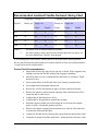
1
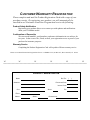
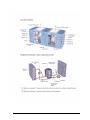
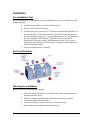
CellarMate
The Key to Wine Cellar Climate Control
Installation, Operation, and Maintenance Manual
CONGRATULATIONS!
on your purchase of a CellarMate Climate Control System. Our climate control
systems are designed to provide you with many years of reliable, maintenancefree service.
Please read the following information, especially the safety information, to
ensure that you receive the maximum benefits of owning a CellarMate,
THE KEY TO WINE CELLAR CLIMATE CONTROL.
CUSTOMER WARRANTY REGISTRATION
Please complete and mail the Product Registration Card with a copy of your
purchase receipt. By registering your product, you will automatically be
enrolled in our Consumer Protection Program and receive the following:
Product Safety Notification
Registering your product allows us to contact you with updates and notifications
about your CellarMate model.
Confirmation of Ownership
We store model numbers, serial numbers, and owner information in our archives for
ten years. In the event of fire, flood, or theft, your registration serves as proof of your
purchase for insurance purposes.
Warranty Service
Completing the Product Registration Card will expedite efficient warranty service.
Please cut on dotted line and mail registration form to: CellarMate LLC, PO Box 257, West Cornwall, CT 06796
PRODUCT REGISTRATION
NAME:
DAY TEL:
ADDRESS:
PURCHASE DATE:
INSTALL DATE:
CITY:
STATE:
EMAIL:
MODEL:
SERIAL:
DISTRIBUTOR:
ZIP:
(
)
Table of Contents
Standard Specifications............................................................................................................. 1
Accessories and Optional Equipment ....................................................................................... 2
Heating Coils ........................................................................................................................ 2
Water Cooled ........................................................................................................................ 2
Duct Collars, Flexible Ducting, and Accessory Kits ............................................................ 2
Low Ambient Option ............................................................................................................ 2
Humidifier and Humidistat ................................................................................................... 3
Overview of the CellarMate Unit ............................................................................................. 4
Cabinet .................................................................................................................................. 4
Condensing Section .............................................................................................................. 4
Evaporator Section................................................................................................................ 4
Electrical Controls ................................................................................................................ 4
Filters .................................................................................................................................... 4
Refrigerant Circuit ................................................................................................................ 4
Supply/Return Grilles ........................................................................................................... 4
Safety Considerations ............................................................................................................... 7
Lockout/Tagout Procedure.................................................................................................... 7
Installation................................................................................................................................. 8
Pre-installation Test .............................................................................................................. 8
Air Flow Illustration ............................................................................................................. 8
Planning the Installation ....................................................................................................... 8
Pre-installation Checklist ...................................................................................................... 9
Placing the Unit..................................................................................................................... 9
Noise Insulation .................................................................................................................... 9
Grilles.................................................................................................................................... 9
Outdoor Installation ............................................................................................................ 10
Mounting the Unit............................................................................................................... 11
Installing the Condensate Drain Connection ...................................................................... 11
Installing the Thermostat and Control Wiring .................................................................... 13
Mounting the Thermostat.................................................................................................... 13
Supply and Return Grills Placement................................................................................... 14
Installing the Ductwork....................................................................................................... 14
Recommended Insulated Flexible Ductwork Sizing Chart..................................................... 15
Ductwork............................................................................................................................. 16
No Ductwork....................................................................................................................... 16
Start Up and Operation ........................................................................................................... 17
Turn the Rocker Switch ON ............................................................................................... 17
Set the Thermostat .............................................................................................................. 17
Test the Fan......................................................................................................................... 17
Operating the Unit............................................................................................................... 17
Cycling the Unit.................................................................................................................. 17
Setting the Thermostat ........................................................................................................ 18
Regulating the Wine Cellar Temperature ........................................................................... 18
Changing the Air Flow Pattern ........................................................................................... 18
CellarMate Manual
Maintenance............................................................................................................................ 19
General Maintenance .......................................................................................................... 19
Cleaning the Filters ............................................................................................................. 19
Cleaning the condensate Drain System............................................................................... 19
Maintenance Schedule ............................................................................................................ 20
Dimensions and Components ............................................................................................. 21
Performance and Specifications.............................................................................................. 22
Typical Mounting Arrangements............................................................................................ 23
Through the Wall Mounts................................................................................................... 23
Ducting Options ...................................................................................................................... 24
Single Outlet Duct Installation............................................................................................ 25
Dual Outlet Duct Installation .............................................................................................. 25
Wiring Diagram – Models 025 and 050 ................................................................................. 26
Wiring Diagram – Models 088 and 200 ............................................................................. 27
Wiring Diagram – Humidifier ................................................................................................ 28
Troubleshooting ...................................................................................................................... 29
Start Up ............................................................................................................................... 29
Unit Does Not Start Up....................................................................................................... 30
High Pressure Switch Has Shut the Unit Down.................................................................. 30
Unit is Operating and Blows Evaporator Air, but the Supply Air is Not Colder Than the
Return Air from the Cellar.................................................................................................. 31
Problems Controlling Cellar Temperature......................................................................... 31
Cellar Humidity .................................................................................................................. 32
Advanced Troubleshooting..................................................................................................... 35
CellarMate Warranty .............................................................................................................. 36
Glossary .................................................................................................................................. 37
CellarMate Manual
Standard Specifications
The CellarMate unit contains,
•
A thermal expansion valve to control the flow of refrigerant into the
evaporator coil.
•
A filter dryer to keep the refrigerant clean and free of contaminants.
•
A sight glass to observe the level of refrigerant.
•
An automatic low pressure switch to prevent low suction pressures and frost
formation on the coil.
•
A manually reset high-pressure switch on the discharge to protect the
compressor from high pressures.
•
Environment-friendly refrigerant, only R-134a.
•
A built-in condensate drain trap--no external trap is required.
The CellarMate meets or exceeds the rated capacities for total BTU/H and CFM at design
cellar conditions and external static pressures. Both the evaporator and condenser fans are
capable of rated CFM against the external static pressure imposed by recommended
ductwork. Both fans are motorized impeller plug fans, statically and dynamically balanced,
with permanently lubricated direct drive motors requiring no maintenance.
All exterior framing of the CellarMate is power coated, 0.063” gauge aluminum to prevent
rust and corrosion. All coils are copper tubes with aluminum fins. The unit uses an external
drain to remove excess moisture and not reintroduce it into the cellar or ambient space.
Removable access panels are provided to facilitate maintenance, duct connections, and
access to wiring components.
The evaporator and the condenser coils have pre-filters on the inlet to prevent dust and dirt
from fouling the coils, reducing capacity. Each unit has at least three discharge outlets on
both the evaporator and condenser coils to facilitate custom installations.
Compressors are rotary, self-lubricating, hermetic reciprocating-type compressors with
internal overload protection and capacitor start. Standard manufacturer’s warranty is one
year. Optional Extended Warranty is five years.
Electric power is supplied by a single cord and plug. All external controls are 24 volt,
supplied from an internal transformer. The 230 volt units are capable of operating at 208 or
240 volt by changing the leads on the control transformer. (See Wiring Diagram)
CellarMate Manual
Page 1
Accessories and Optional Equipment
Heating Coils
The optional heating coil is built-in and requires no additional power source. The electric
heating option is factory installed and includes primary and secondary over-temperature
protection devices per UL and NEC. It is located between the evaporator coil and the blower
inside the transition duct. It contains the heating element and high-temperature limit
switches. The heating coil is wired to work in conjunction with the thermostat. Since the
thermostat prevents the heating and cooling circuits from being on at the same time, no
additional power wiring is needed. Set the auto mode on the thermostat so it can
automatically switch from heating to cooling
No maintenance is required for the heating coil. To test the heating coil operation, set the
thermostat on heat and set the temperature above the cellar temperature. The supply air
temperature should rise above the return air.
Water Cooled
A water-cooled option is available that uses a tube-in tube heat exchanger in place of the
condenser coil and fan. Waste heat from the refrigerant is transferred to the water. A control
valvue is used to regulate the flow of water to maintain head pressure. Leaving water is
clean and acceptable for other applications. (This option available for the 025 model in the
second quarter of 2005).
Duct Collars, Flexible Ducting, and Accessory Kits
Duct Collars
Duct collar adaptors are mounted on either a large panel (21”x12”) or a medium panel
(12”x12”), and come in two diameters; 10” for the CM050, CM088, and CM200, and
8” for the CM025. The duct collar adaptors replace the removable solid panels on the
unit. (Refer to the Air Flow Illustration on page 8 8 for panel locations, and Ppanel
sSizes on Page 215.)
Flexible Ducting
The flexible ducting is a 25’ foot length of 10” insulated ducting for the CM050,
CM088, and CM200 and 8” insulated ducting for the CM025.
Accessory Kits
An accessory kit consists of two duct collar adaptors (one of each size panel) and one
25’ length of flexible ducting. Accessory kits come in both 10” and 8” diameters.
Low Ambient Option
A factory installed Low Ambient Option (LAO) is available which makes the CellarMate
capable of exposure to low ambient temperatures. This feature controls the condenser fan
operation based on head pressure and heats the oil reservoir. The LAO is recommended
whenever the condenser section is exposed to air temperatures below 40°F.
CellarMate Manual
Page 2
The LAO will protect the compressor and refrigerant system. It has two distinct components;
a crankcase heater to keep the oil in the compressor warm and prevent slugging on start-up,
and a head pressure control to automatically cycle the condenser fan on and off to maintain
system head pressure.
To confirm that the system is working, feel the bottom of the heater when the compressor
unit has cycled off. When the unit starts, the condenser fan does not start at the same time as
the compressor. The condenser fan starts after the head pressure has built up. As the unit is
running, the condenser fan cycles off and on while it holds the head pressure within a fixed
range. The colder the air, the more frequent the cycling and the longer the duration.
Humidifier and Humidistat
A popular option for the CellarMate is the humidifier, supplied with a sheet metal adapter
box and a pre-wired humidistat. The humidifier is designed for field installation and can be
retrofitted onto existing CellarMate units. Each humidifier model is furnished with an
electronic digital humidistat to control the humidity in the cellar. The humidifier mounts
onto the CellarMate unit using the common drain, and requires a hot water supply. No
additional external power is required.
When the humidistat calls for humidity, a damper inside the enclosure opens and allows air
from the evaporator fan to flow through the drip pad and back into the inlet of the unit. A
solenoid valve also opens, allowing water to flow into the distribution channel and drip down
over the pad. The air flowing over the wet pad surface adds moisture to the air and increases
the humidity in the cellar.
Since the cellar air temperature is cold, the water entering the humidifier must be HOT to be
absorbed into the air stream. To avoid the buildup of dirt on the pad, install a 5 or 10 micron
inline water filter ahead of the humidifier to keep dirt from fouling the evaporation pad
inside. To avoid the buildup of mineral deposits on the pad, install a water softener.
To insure adequate wetted surfaces and help flush away excess minerals, set the water flow
to always have a flow of water to the drain. When operating, the humidifier uses
approximately 1 to 2 gallons of water per hour. About 60% of the water passes through and
goes out the drain. There is an orifice in the line to restrict the flow of water, but a throttling
valve may be needed to keep too much water from going to the pad. All that is needed is a
steady drip of water out of the drain to ensure adequate wetting and flushing of the pad
media. Pipe a gravity drain line to an open floor or sink drain, or use a condensate pump
where a gravity drain is impractical. Discharge the excess drain water directly onto the
ground, or combine the discharge into the condensate drain from the unit, but only
downstream from the loop trap.
The CellarMate humidifier uses a 10” wide x 11” high x 2”thick pad. The rated output
capacity for wine cellars at 55°F is 1.62.3 gallons per day (gpd) with 760°F water supply,
34.57 gpd with 950°F water, and 7.45.1 gpd with 120°F water. Weight of operating
humidifier is 10 lbs.
CellarMate Manual
Page 3
Overview of the CellarMate Unit
Cabinet
The cabinet and access doors are constructed of aluminum with a powder coated finish for
corrosion protection and an attractive, maintenance-free appearance. Areas in contact with
cold temperatures are lined with insulation to prevent condensation.
Condensing Section
Ambient air is circulated through the condenser section by a blower. This section also
contains the compressor and the electrical controls. If the water cooled option is purchased, a
heat exchanger is used in place of the condenser coil and blower.
Evaporator Section
Cellar air is circulated through the evaporator section by a impeller blower. The large
evaporator coil face area eliminates condensate carry-over, reduces air pressure drop and
optimizes heat transfer. A drain pan is located directly below the coil to capture condensate
and is fabricated from aluminum to prevent rust and corrosion. The electric heating coil, if
ordered, is factory installed between the evaporator coil and the blower, and is complete with
contactor(s) and limit controls.
Electrical Controls
The electrical components and controls are located in a separate area accessible through the
condenser section. All wiring is in accordance with the National Electrical Code. Wires are
numbered and color coded to match the wiring diagrams.
Filters
Nominal 1” thick filters are provided on both the evaporator and condenser inlets to protect
the coils from dust and dirt. These filters are washable and reusable.
Refrigerant Circuit
The factory-charged circuit includes an adjustable thermal expansion valve with an external
equalizer, sight glass with moisture indicator, a filter dryer, an automatic low pressure
switch, and a manually reset high pressure switch. For the low ambient option, an automatic
pressure switch controls the operation of the condenser blower and a heating element is
added to the compressor oil reservoir.
Supply/Return Grilles
Powder-coated steel single direction grilles are provided for the inlets on the evaporator and
condenser sections. One grille is provided on an outlet. These are readily interchangeable
with access panels to control and direct the air flow.
CellarMate Manual
Page 4
Grilles: Additional grilles are available. Medium grilles are
used for top or side ports; large grilles are used for end ports.
See unit dimensions on Page 21.
Duct collars: Duct collars are available. Medium collars are used
for top or side duct ports; large collars are used for end ports. See
unit dimensions on Page 21.
Cover plates: Solid cover plates are available. Medium plates are
used for top or side parts; large plates are used for end ports. See
unit dimensions on Page 21.
CellarMate Manual
Page 5
CellarMate Manual
Page 6
Safety Considerations
When performing maintenance, always use the following Lockout/Tagout Procedure. More
than one power source may be present. Disconnect all power sources.
Lockout/Tagout Procedure
Turn power switch to OFF. Lights should be off.
Unplug unit from electrical outlet
WARNING
•
Never reach into a unit while the fan is running.
•
Never open an access door downstream of the fan while the fan is running.
•
Do not expose the unit to rain or moisture.
•
Check weight specifications to confirm that supports are adequate.
•
Confirm that supports are designed to meet local codes and ordinances.
•
Do not remove access panels until fan impellers have completely stopped.
Fan impellers continue to turn (free-wheel) after the power is turned off.
•
Never pressurize equipment above the specified test pressure. (See
Specification Sheet)
•
Do not operate near water.
•
Do not block any supply or return air register.
•
Do not modify or change polarized or grounding plugs. If the provided plug
does not fit into the outlet, consult an electrician for replacement of the
obsolete outlet.
•
Only use attachments/accessories specified by the manufacturer.
•
The CellarMate unit only operates on 120 VAC or 230 VAC, 1 phase 60Hz
power source.
•
Always ground the outlet to provide adequate protection against voltage
surges and static charge build-up.
•
Refer all service to qualified personnel.
•
Do not place anything on top of the unit.
•
Do not use extension cords.
•
Use only dedicated power outlet boxes of the specified capacity and
configuration for the unit model.
CellarMate Manual
Page 7
Installation
Pre-installation Test
Before installing your CellarMate unit, use the following procedures to test for non-visible
shipping damage.
•
Set the unit of the floor or on a sturdy level surface.
•
Plug the power cord into an outlet.
•
Turn the main power switch to ON. The power indicator light should be on.
•
Override the timer: The built-in timer prevents short cycling and keeps the
unit from turning on right away. Open the thermostat cover. Simultaneously
press the fan and UP arrow buttons. The unit will run as long as the
temperature of the space is above the thermostat set point. After several
minutes, the unit will expel cold air from the evaporator section and hot air
from the condenser section.
•
Listen for unusual noise or vibration.
Air Flow Illustration
Planning the Installation
Before installation, determine the following:
•
Where the unit will be located; e.g. built into the wall or mounted remotely
and ducted into the cellar.
•
Where the supply and return grills will be placed to achieve preferred
temperature gradient and circulation.
•
Location of the power outlet (do not use an extension cord).
•
If the condenser heat exhaust will be ducted away.
CellarMate Manual
Page 8
•
Where to place the thermostat.
•
Where to run the drain line.
•
All required parts are on-hand.
•
Pre-installation Checklist
Before installation, confirm the following:
•
The electrical plug has the correct configuration.
•
Breakers are the proper size
•
The cellar has adequate insulation and vapor barrier
•
Ducts are the correct size
•
There is ample space around the unit to allow access for maintenance and
repair
Placing the Unit
CellarMate units are typically installed indoors, near the cellar to minimize the length of the
duct run. Each unit is provided with one entering or return air inlet and three possible supply
air outlets for the evaporator and condenser sections. A maximum cumulative length for
both supply and return ducts of 50’ is recommended. If longer runs are needed, use more
than one supply opening to reduce the air flow in each duct by half.
Provide a 3’ access clearance around the unit for maintenance access. If a humidifier is
installed, leave space in front of it for service access.
Noise Insulation
When placing the CellarMate unit close to the cellar or next to an occupied space, insert a
piece of 1” or 2” dense rubber or foil-faced Styrofoam between the unit and the wall to
absorb noise.
Grilles
CellarMate units come from the factory with grilles over the openings of each of the inlets
and three of the outlets. Remove the grilles as needed to install ductwork between the unit
and the cellar.
The return air, or inlet, to the unit must connect to the return air outlet from the cellar.
Any of the three supply air outlets on the unit can be used for the ductwork to the supply
grille inside the cellar. The factory installed outlet grille can be moved to any of the other
two openings.
In most cases, no ducts are installed on the condenser section because the unit is located in a
mechanical or storage space. If exhaust heat is undesirable, use the grilles to duct the heat
outdoors or to another space.
CellarMate Manual
Page 9
Outdoor Installation
CellarMate units are not designed for outdoor installation. If the unit must be installed
outdoors, use a rain-proof enclosure and low-ambient kit.
•
Mount the unit above the ground on a solid, waterproof base to protect the
unit from ground water.
•
Keep the area around the unit clean and free of debris.
•
It is recommended to double insulate the ducts with exterior grade insulation
to keep them dry and effective. Place one flexible duct inside a larger size
duct where ductwork is exposed.
•
Allow ample space at both ends of the unit for service access.
CellarMate Manual
Page 10
Mounting the Unit
Floor Mounting
Elevate the CellarMate on a 2”x4” frame with a plywood surface to protect it from
water. Allow adequate space for the external drain.
Wall Mounting
Confirm that the load bearing capacity of the supports is adequate and meets local
codes and ordinances. Support the CellarMate on both sides of the wall. Use floor or
knee braces to transfer the load of the unit to the floor or wall.
Ceiling Mounting
CellarMate units are not designed for suspension from the top of the unit.
Construct a structurally sound platform on which to place the unit when hanging from
ceiling joists. Ensure that the platform is supported on all four corners.
Leave adequate space above the unit for service access.
To operate properly, the unit must be level within ¼” end to end and 1/8” side to side.
Place the unit as close to the wine cellar as possible to reduce the length of the duct
runs. Use straight, short ducting. To prevent transmitting vibration and noise, add
¼” thick rubber pads.
Installing the Condensate Drain Connection
The CellarMate dehumidifies the inside of the wine cellar. If the wine cellar vapor barrier is
poorly constructed or there is excess moisture in the adjacent area, the unit will remove the
excess moisture from the wine cellar.
Installing the Drain Line
1. Extend the drain line from the unit to an external drain or disposal site. Use
½” ID drain tubing or larger.
2. Splice the drain extension onto the drain outlet with a short piece of ½”
copper tubing and secure with clamps.
3. Install with a minimum pitch of ¼” per linear foot to allow the drain line to
function by gravity. Do not tie the condensate drain line directly into a
sanitary sewer system.
Your CellarMate unit has a built-in drain trap which creates a water seal to prevent air
from backing up into the drain pan and causing the drain pan to overflow.
Priming the Drain Trap
The internal drain trap primes itself automatically once the unit has run for a period of
time and after the unit cycles OFF. When functioning, water will drip from the drain.
Wiring the Unit for Power
CellarMate Manual
Page 11
WARNING
Note: The electrical outlet and wiring installation must meet national and local
building codes.
•
Use an electrical outlet configured to match the plug on the CellarMate.
•
Confirm that the wiring and breaker conform to the rated load listed on the
serial plate. See illustration below.
•
•
Use a dedicated circuit and wiring.
•
Do not modify the plug in any way.
•
Do not use extension cords.
IMPORTANT
Use only 115 volt or 230 volt (depending on model) AC1 phase/60 cycle power
supply with a variance no greater than +/-4% to avoid damage.
CellarMate Manual
Page 12
Installing the Thermostat and Control Wiring
CellarMate units come with a thermostat and 25’ of wiring. They are wired at the factory
and tested before shipping. This wiring can be used for an initial start-up on-site. See “Startup Instructions” in the thermostat guide for installation and operation.
Removing the Wires for Installation
•
Note the color coding on the wires before removing
•
Using the proper screwdriver, loosen the screws and pull the wires free.
Reinstalling the Wires
•
Realign color coded wires
•
Wrap each wire around the screw and tighten the screw.
Additional Wiring
•
Splice onto the factory furnished wire
•
Match the wire colors for continuity
•
Insulate the splice with electrical tape
WARNING
Incorrect thermostat wiring will result in improper operation and may cause
damage to the unit and thermostat.
Confirm that each colored wire is connected to the appropriate color-coded
slot on the terminal strip, and that the connections are secure.
Mounting the Thermostat
Two sets of instructions are provided with the unit; the Homeowner’s Guide and the
Installation and Operation Instructions Guide. Use the Homeowner’s Guide to set and
operate the thermostat. Review the Installation and Operating Instructions Guide to learn
about the features of the thermostat.
Mount the thermostat on a solid surface, away from doors, corners, air outlets, drafts, or heat
generating equipment. Do not mount the thermostat directly on an outside wall or on a wall
adjacent to a boiler room. Place a piece of foam insulation behind the thermostat to insulate
it from heat and cold. The recommended height is 4 to 5’ above the floor.
Thermostat Setting Options
The thermostat is Model AC, intended for 1 stage cooling and 1 stage heating.
Option 02 – Under configuration has a “Change Filters” alert. The alert is
determined by hours of fan (blower) operation and can be set between 400 and 3600
hours. The original factory setting is 800 hours, but can be changed. The required
CellarMate Manual
Page 13
number of hours between filter changes is determined over time for each individual
unit and installation.
Option 04 – The optional heating coil is ON. In addition to cooling, this setting
energizes the evaporator fan when heat or humidity is required.
Option 15 – The automatic switch for the thermostat is ON. This setting
automatically switches the thermostat from the heating mode to the cooling mode.
Only for units ordered with the optional heating coil.
Built-in Time Delays
Time delays are built into the CellarMate to protect the components from damage due
to short cycling. Note the various time delays that are explained in the Installation
and Operating Instructions Guide.
* When the COOL ON indicator is flashing, the unit is waiting for the timer before
starting.
Supply and Return Grills Placement
Place the supply and return registers inside the cellar to create an air flow patter that
maximizes air circulation in the room. Avoid short circulating the air.
•
To avoid collecting dust, do not install the return air registers directly on the
floor.
•
Avoid placing the supply or return grilles where they are blocked by bottles,
boxes, or cases.
•
Avoid placing the supply air grille so it blows directly on the thermostat.
The following installation diagrams are for general ideas only. They are not intended to be
complete, detailed installation drawings. For questions regarding installation, contact your
distributor. If further assistance is required, contact us at 888-564-2932, or email
[email protected], or fax your inquiry to 860-672-6347.
Installing the Ductwork
Use ductwork to connect the unit to the supply and return outlets in the wine cellar. Use only
insulated ductwork to minimize cooling loss, prevent sweating, and reduce noise.
Use ductwork on the condenser section to redirect or absorb sound, bring conditioned air to
the unit inlet, and to exhaust hot air out of the ambient space. Follow the recommendations
and warnings for duct installation.
Note:
DO NOT EXCEED A TOTAL OF 25’ FOR EACH LENGTH OF DUCTWORK RUN.
CellarMate Manual
Page 14
Recommended Insulated Flexible Ductwork Sizing Chart
Model #
Evaporator (cooling) Coil
Condenser (heat rejection) Coil
Return Air Supply Air
Return Air Supply Air
Single
Double
Single
Single
Double
025
8”
8”
6”
8”
8”
6”
050
10”
10”
6”
10”
10”
6”
088
10”
10”
8”
10”
10”
8”
200
12”
12”
10”
12”
12”
10”
Notes: 1.
The above sizes are internal diameter in inches
2.
If a single supply is used out of the unit, but then splits into two ducts, use
the sizes indicated for “Double” after the split.
Avoid crimping the flexible ducts, which reduces air flow and causes erratic operation.
Be sure that all ducts and surfaces that are in contact with the air flow are insulated and have
a vapor barrier on the outside surface.
General Duct Recommendations
•
Support the flexible duct often to prevent sags or bends. (Place supports close
enough to prevent the flexible ducting from sagging or bending).
•
Stretch the duct to create a smooth interior and reduce air resistance. Rigid
ductwork is best.
•
Insert a metal elbow in the flexible duct at 90° bends to maintain form.
•
Use straight and short lengths of ductwork.
•
Review the Air Flow Illustration on page 8 for duct connection options.
•
Remove the panels or grilles from the openings where the ductwork will be
connected and save the screws.
•
Confirm that all fan blades move freely.
•
Confirm that no foreign objects obstruct the air paths.
•
Install the panels with the duct collars using the screws from the original
panels or grilles. Handle the gaskets with care.
•
Pull the outer plastic wrapping and insulation away from the end of the duct
to expose the reinforced duct liner.
•
Connect the flexible duct by inserting the exposed portion into the duct collar.
•
Clamp the tie straps around the inside liner. Fasten the duct to the duct collar.
CellarMate Manual
Page 15
WARNING
Do not clamp the tie straps around the outside insulation—
Over time, insulation will compress and loosen.
•
Secure the duct collar panel to the unit using the screws set aside.
WARNING
Non-insulated ducts and surfaces can cause exposed metal surfaces to sweat,
further degradation of the insulation, and a loss of equipment cooling
capacity.
Ductwork
Cold Air to the Wine Cellar
•
Remove the supply air grille or access door panels to install the ductwork
from the CellarMate to the wine cellar.
•
Connect the supply air ductwork from the cellar to the supply air outlets at the
CellarMate unit.
•
Connect the return air ductwork from the cellar to the return air inlet at the
CellarMate unit.
Warm Air to the Condenser
•
Connect ductwork on the condenser to direct heat and sound away from
occupants.
•
Connect ductwork to another space within the basement, a building, or to the
outdoors if the heat being exhausted will raise room temperature.
No Ductwork
The supply and return grilles stay on the unit if no ductwork is used. Additional solid panels
may be required; available from your distributor or CellarMate.
CellarMate Manual
Page 16
Start Up and Operation
•
Check all ductwork and electrical connections to confirm they are secure.
•
Replace all panels that were removed during installation.
•
Make sure that all openings on the unit are covered with either a panel,
ductwork collar, or a grille.
Turn the Rocker Switch ON
Turn the rocker switch (on top of the unit) to ON. The switch will light up to indicate that
the unit is receiving power. The unit may not begin operating immediately due to the built-in
timer which prevents short-cycling.
Set the Thermostat
Refer to the thermostat instructions. Set the thermostat to AUTO and 55°F.
Test the Fan
Push the FAN button on the thermostat to switch from AUTO to FAN as indicated on the
display screen.
FAN -
The fan runs continuously and indicates that the power is ON
and the control circuit is energized and operating.
AUTO -
The fan runs when the thermostat calls for cooling or heat, or
the optional humidistat calls for humidification.
Operating the Unit
Listen for the compressor. The hum will be audible, with no excessive vibration or sounds.
Initially, the unit may run continuously for several hours—up to a day or more—while it
lowers the cellar temperature. Once the unit reaches the set point temperature, it will turn off
and then begin to cycle on and off as it continues to lower the bottle temperature to the set
point. The cellar air temperature will reach the set point before the bottle temperature. If the
cellar air temperature started at 75°F, the supply air discharged by the unit will be 15 to 20°F
colder. As the cellar air temperature decreases to 55°F, the difference in the supply air
temperature will decrease to 8 or 12°F.
Cycling the Unit
The fans will continue to free-wheel for several minutes after the unit cycles off. This is
normal.
If the unit is equipped with a low ambient control, the condenser fan will also cycle on and
off during cooling. This will maintain the head pressure on the compressor under low
ambient conditions. The bottom of the compressor stays warm, even when the unit is OFF,
to keep the lubricating oil warm and separate from the refrigerant.
CellarMate Manual
Page 17
Setting the Thermostat
Normal settings are between 54 and 58°F. If the unit is equipped with an optional heating
coil, enter a separate temperature setting to maintain the lower setting. To prevent the unit
from short cycling, the setting between heating and cooling cannot be closer than 2°F. The
built-in delay timer (20 minutes) will prevent the unit from switching from heating to cooling
too fast.
Regulating the Wine Cellar Temperature
Wine cellars have a temperature gradient of 5 to 10° between floor and ceiling. Change the
air flow patterns to raise or lower the temperature in different zones.
To maintain the same temperature throughout the wine cellar, set the thermostat to FAN so
the supply fans run continuously while the unit is cooling, as opposed to AUTO.
To switch from continuous to automatic mode, press the FAN button on the thermostat.
To switch back to automatic mode, press the FAN button again.
Changing the Air Flow Pattern
The CellarMate is equipped with single-direction grilles. Rotate the grilles 180° to change
the direction of the air flow.
When using multiple-supply ductwork, balance the air flow between the ductwork. If too
much air flows through one duct and not enough air flows through the other duct, install a
damper or other restriction device into the duct with too much air. This will force more air to
flow from the other duct.
CellarMate Manual
Page 18
Maintenance
General Maintenance
WARNING
Before performing maintenance on the unit, read the safety information contained within the
safety chapter of the CellarMate Manual.
High voltages are present in the cabinets. Turn all power OFF. Use the Lockout/Tagout
procedure before opening panels.
Maintenance on CellarMate units requires working with high voltage and sheet metal with
sharp edges. Only qualified personnel should perform maintenance. Some tasks require
knowledge of mechanical and electrical procedures. Make sure you are familiar with all
hazards, general safety-related procedures, and safety labels on the unit.
The CellarMate is designed for minimum maintenance. The refrigerant is hermetically
sealed and requires no maintenance. The fans are permanently lubricated and require no
maintenance. Some maintenance may be required if there is dust or dirt in the air stream.
Cleaning the Filters
The evaporator and condenser coils are equipped with reusable, washable air filters. The
filters protect the coils from becoming coated or plugged by dust. Clean the filters based on
the amount of dust or dirt generated in the cellar or basement.
1.
2.
3.
4.
5.
6.
Remove the grille or duct collar on the inlet end of the unit.
Remove the filter covering the face of the coil
Rinse the filter with warm water and shake off excess water.
Inspect and clean the face of the coil.
Reinstall the filter.
Replace the grille or duct collar.
Cleaning the condensate Drain System
The condensate drain system traps dust and dirt. Clean the drain system once a year.
1.
2.
3.
4.
Shut off the rocker switch and unplug the unit.
Remove the grille or duct on the evaporator inlet.
Remove the filter and inspect the drain pan under the coil.
If the drain pan is soiled, pour some hot water mixed with liquid bleach along
the length of the pan to flush the dirt down the drain tube.
5. Continue this treatment until the loop in the drain is clean and free of dirt.
6. Reinstall the filter and grille or duct collar.
7. Plug the unit in and restart.
CellarMate Manual
Page 19
Maintenance Schedule
Monthly
•
Check filter and drain trap – clean if needed
•
Check for noise or vibration
•
Check for short-cycling of the unit
•
Replace filters if worn or plugged beyond cleaning
•
Check evaporator and condenser coils for dirt. Use a vacuum with the brush
attachment to clean the coils.
•
Clean condensate pan under the evaporator coil by flushing. Keep the drain
pan clear of debris.
•
Inspect the cabinet for corrosion or rust.
•
Inspect for dirt build-up on or inside the unit. Clean the unit by vacuuming or
wiping it down.
•
Check for loose insulation, fasteners, gaskets, or connections.
•
Check the wiring connections and integrity of cords
•
Examine ducts for any cracks or breach
•
Check damper and solenoid on humidifier
•
Replace humidifier pad
Annual
CellarMate Manual
Page 20
Dimensions and Components and Components
CellarMate Manual
Page 21
Performance and Specifications
CellarMate Manual
Page 22
Typical Mounting Arrangements
The following illustrations are suggested mounting arrangements. These illustrations are not
intended to be complete and detailed installation drawings.
Through the Wall Mounts
CellarMate Manual
Page 23
Ducting Options
CellarMate Manual
Page 24
Single Outlet Duct Installation
Dual Outlet Duct Installation
CellarMate Manual
Page 25
Wiring Diagram – Models 025 and 050
CellarMate Manual
Page 26
Wiring Diagram – Models 088 and 200
CellarMate Manual
Page 27
Wiring Diagram – Humidifier
CellarMate Manual
Page 28
Troubleshooting
IMPORTANT
This section is intended as a diagnostic aid, only. For detailed repair or parts
replacement procedures, contact a qualified service company. Check the
following table before calling a service technician.
Start Up
POSSIBLE CAUSE
SOLUTION
Loose, improper, or defective
thermostat or humidistat
wiring
Check power and thermostat or humidistat
wiring.
Incorrect thermostat or
humidistat (optional) settings
Check the thermostat and optional humidistat
setup for the application. Read the thermostat
troubleshooting guidelines in the Thermostat
Installation and Operating Guide.
Changed settings on the
thermostat
The internal timer did not complete the timed
delay. Follow the manufacturer’s instructions to
override the timer.
Blockage of the evaporator or
condenser air flow. If the air
flow becomes blocked, the
manual reset high limit switch
opens and shuts the unit off.
Turn the rocker switch to OFF
Check for obstruction of the air flow
Remove the obstruction
Inspect the air filter for dirt and dust
Clean or replace the filter
Unit shuts off
Locate the high pressure switch near the
compressor (a cylindrical device piped into the
refrigeration system with two wires and a red
button on the top)
Push the button until it locks into place.
Push the rocker switch to restart the unit
CellarMate Manual
Page 29
Unit Does Not Start Up
Power Switch Light is Off
Possible Cause
Solution
Switch not on
Turn on switch
No power to outlet
Check circuit breaker and wiring
Unit not plugged in
Plug in the unit
Power Switch Light is On and the Thermostat Light is OFF
Possible Cause
No power to thermostat
Solution
Check wiring for loose, broken, or frayed
connections.
Check transformer for 24v output to thermostat
Power Switch Light is ON and the Thermostat Light is OFF
Possible Cause
Solution
Thermostat is not setup
properly
Check thermostat setup in the guide
Press fan ON switch to check evaporator fan,
only
Compressor not operating
High pressure switch open (button up)
Condenser air flow is blocked
Remove blockage
Clean filter and coil (if needed)
HP switch is open
Reset HP switch (push button in)
High Pressure Switch Has Shut the Unit Down
Possible Cause
Head pressure in unit is too
high because an obstruction is
restricting air flow through the
condenser
CellarMate Manual
Solution
Remove the obstruction in the duct or grille or
clean the filter. Restart the unit using the high
pressure switch near the compressor (a cylindrical
device piped into the refrigeration system with
two wires and a red button on the top) and push in
the button until it locks into position again. Push
the rocker switch to restart the unit
Page 30
Unit is Operating and Blows Evaporator Air, but the Supply Air is
Not Colder Than the Return Air from the Cellar
Possible Cause
Solution
Thermostat not set up properly
Check thermostat set up in the manufacturer’s
thermostat guide.
Compressor not operating
High pressure switch open (button up)
Condenser air flow is blocked
Remove blockage, clean filter and coil (if needed)
Head Pressure (HP) switch is
open
Reset HP switch (push button in)
Problems Controlling Cellar Temperature
Problems are occurring even though the unit seems to be fully operational—evaporator fan
blows air into the cellar and compressor and condenser fan runs.
Cellar Temperature is Too Low (Below 51°) When Unit is Running
Possible Cause
Solution
Thermostat set too low on
cooling
Reset thermostat to higher cooling temperature
Heating coil (optional) not
operating
Rest thermostat to higher heating temperature
Thermostat not controlling
temperature
Wiring integrity compromised (shorted), replace
wiring
Cellar Temperature is Too Low (Below 51°) When Unit is Not Running
Possible Cause
Too much heat loss to adjacent
spaces
Solution
Increase insulation around the ductwork and
doorways
Add heater
CellarMate Manual
Page 31
Cellar Temperature is Too High, but Supply Air is Cold
Possible Cause
Solution
Not enough evaporator air
flow
Remove blockage in supply or return ductwork
Check and clean filter and coil
Coil frozen—shut-off unit for two hours
Cellar loads are too high
Install additional insulation
Replace with larger unit
Cellar Humidity
Humidity Too Low or Supply Air is Too Cold, Without Optional Humidifier
Possible Cause
Solution
Not enough evaporator air
flow
Remove blockage in supply or return ductwork
Check and clean filter and coil
Coil frozen—shut-off unit for two hours
Defective Thermal Expansion
Valve
If under warranty, call for service
If not under warranty, call a refrigeration
technician
Humidity Too Low Without Optional Humidifier
Possible Cause
Solution
No moisture being added to
cellar
Add CellarMate humidifier or a room humidifier
Defective Thermal Expansion
Valve
If under warranty, call for service
If not under warranty, call a refrigeration
technician
CellarMate Manual
Page 32
Humidity Too Low With Optional Humidifier
Possible Cause
Solution
Humidifier not operating
Check wiring for loose, broken, or frayed
connections
Check humidistat setup
Check for water flow & solenoid valve operation
Check damper operation
Humidifier operating
Check for water being hot
Check drip pad—replace if scaled
Inadequate vapor barrier around cellar
Humidity Too High When Unit is Running, But Not Cooling
Possible Cause
Compressor
Solution
Check and reset high limit switch
Clear blockage of condenser air flow
Ambient temperature above 95°F
Humidity Too High When Unit is Not Running
Possible Cause
Unit needs to run to
dehumidify
Solution
See Unit Not Operating section of the
Troubleshooting section
Humidity Too High When Unit is Running and Cooling
Possible Cause
Solution
Too much evaporator air
Add some resistance to air flow. Install a damper
in the ductwork.
Too much moisture in cellar
Poor vapor barrier installation
Humidifier shutter is stuck open
Humidifier valve is stuck open
Humidifier is set too high
CellarMate Manual
Page 33
Unit Operates but the Power Switch Light is Not On
Possible Cause
Solution
Bulb is burned out
Replace bulb
Unit is Leaking Water
Possible Cause
Solution
Trap plugged
Clean trap
Condensate pan plugged
Remove blockage and clean
Unit not level
Level with shims
Unit is Running Properly, but the Sound of Unit is Objectionable
Possible Cause
Solution
Noise is from air flow
Redirect air flow
Add baffles
Add insulated ductwork
Noise is from unit
Add sound baffle between unit and occupied
space
High Pressure Switch in the Refrigeration System Switch Shuts off Unit
Possible Cause
The head pressure is above 275
psi
CellarMate Manual
Solution
Restricted air flow through the condenser caused
by an obstruction blocking the air flow in the
ductwork or grille
Dust covering the filter
Contact a refrigeration technician
Page 34
Advanced Troubleshooting
IMPORTANT
This section is for qualified refrigeration service technicians, only. The technician should
repeat the previous troubleshooting steps before these more technical solutions.
Evaporator Coil is Freezing
Possible Cause
Solution
Charge too low
Check sight glass
Check for leaks
Add refrigerant
TXV malfunctioning
Repair or replace
High Pressure Switch Keeps Opening Even After Checking for
Obstructions and Dirty Filters/Coils
Possible Cause
Solution
Condenser fan not operating
Repair or replace
Defective switch
Replace
Unit Cycles On and Off More than 8 Times/Hour
Possible Cause
Solution
Thermostat malfunctioning
Refer to the thermostat guide
Low suction pressure
Check low pressure switch
Check pressure and adjust superheat
High Pitched or Loud Rubbing Noise, Clanking, or Vibration
Possible Cause
Solution
Fans loose or malfunctioning
Repair or replace
Excessive compressor vibration
Replace
TXV malfunctioning
Repair or replace
Replacing the Blowers
When replacing the fan or motor, replace the fan and motor as a unit. Do not remove
the motor from the impeller wheel.
CellarMate Manual
Page 35
CellarMate Warranty
General
CellarMate LLC warrants to the original buyer its goods and all parts thereof to be free from defects in material
and workmanship for one year from the date of invoicing assuming NORMAL USE AND SERVICE.
Liability
CellarMate LLC liability shall be limited to the repair or replacement (at its option) of any part, which, at our
sole discretion, is determined to be defective. The purchaser shall pay all transportation costs. Additionally, if
a malfunction occurs within 90 days from the date of invoice, CellarMate LLC will reimburse the reasonable
cost of labor required for the repair or replacement provided authorization is obtained from one of our
authorized representatives prior to incurring any labor charges.
Limitations of Liability
THESE WARRANTIES ARE MADE IN LIEU OF ALL OTHER WARRANTIES EXPRESSED OR
IMPLIED, INCLUDING ANY IMPLIED WARRANTY OF MERCHANTABILITY OR FITNESS FOR A
PARTICULAR PURPOSE AND IN LEU OF ANY OTHER OBLIGATION OR LIABILITY, INCLUDING
LIABILITY FOR ANY INCIDNTAL OR CONSEQUENTIAL DAMAGES. CellarMate LLC will not be
responsible for any costs or liability whatsoever resulting from improper installation or service of its equipment.
In the event that CellarMate LLC or its distributors are found liable for damage based on any defect or
nonconformity in the products, their total liability for each defective product shall not exceed the purchase price
of such defective product. No person or representative is authorized to change these warranties or assume any
other obligations or liabilities for CellarMate LLC in connection with the sale of its systems.
Indemnification
Purchaser agrees to indemnify, hold harmless and defend seller and its officers, directors, agents, and
employees from and against any and all claims, liabilities, costs and expenses arising out of or related to
Purchaser’s use of the goods, or in any way involving injury to person or property or accident occasioned by the
goods sold by CellarMate LLC to Purchaser.
Foreign Government and Indian Nations
If Purchaser is a foreign government or an Indian nation, Purchaser herby expressly waives its defense of
sovereign immunity in the event of a dispute between Purchaser and CellarMate LLC regarding this invoice and
Purchaser expressly acquiesces to the jurisdiction of the federal and state courts of the United State.
Severability
If one or more of the provisions contained in this contract shall for any reason be held to be invalid, illegal, or
unenforceable in any respect, such invalidity, illegality , or unenforceability shall not affect any other provision
of this contract, but this contract shall be construed as if such invalid, illegal, or unenforceable provision had
never been contained.
Additional Requirements
If a defect covered by the Warranty occurs, contact CellarMate LLC for authorization to proceed with
corrective action. Do not return any parts or incur any charges for which you expect to be reimbursed under
this Warranty without receiving this authorization. If parts are replaced under this Warranty, the defective parts
must be returned prepaid within 30 days. This Warranty shall be null and void in its entirety if the Serial
Number on the air conditioner or compressor is altered, removed, or defaced.
CellarMate Manual
Page 36
Glossary
Ambient Air – The surrounding area outside the cellar such as a room, basement, or garage.
BTU/H – Cubic feet per minute. A unit of measure for the amount of air handled by the fan.
Cellar – The wine storage area being conditioned by the CellarMate LLC.
Condensate/Condensation – The water formed out of the air when it is cooled below a
certain temperature (called the dew point), often referred to as “sweating” on pipes and cold
surfaces. This water collects at the bottom of the evaporator or cooling coil and drains out of
the unit through the drain line.
Discharge Air – The air leaving the evaporator condenser section of the CellarMate LLC
unit.
Evaporator (cooling) Section/Coil – The evaporator section uses the cooling coil and the
fan to remove heat from the air inside the wine cellar to the refrigerant, cooling the air and
condensing moisture out of the air. The word “evaporator” refers to the evaporation of the
refrigerant from a liquid to gas phase in the coil. The evaporation section is connected to, or
inside, the wine cellar.
Flexible Duct – Round ducts with a steel reinforced plastic liner, a layer of insulation, and an
outer plastic layer used to convey the air from the unit to the cellar or ambient.
Grille or Diffuser – Inlet or outlet plates to direct the air flow or protect the inside of the
unit.
Heat Gain/Loss – The amount of cooling or heating expressed in BTU/H gained or lost in or
out of the wine cellar to the ambient space. The CellarMate LLC must offset this load.
Inlet Air – The air entering the evaporator and condenser sections of the CellarMate LLC
unit.
Recovery – The amount of cooling the unit does to return the cellar to is set point
temperature after some new load is introduced, such as people or new cases of warm wine in
the cellar.
Return Air – The air leaving the cellar and returning to the inlet of the coil.
SP – Static Pressure. Unit of measure (in inches of water column) of the pressure of the air
handled by the fan.
Set Point – The desired temperature or humidity set on the thermostat or humidistat.
Supply Air – The air entering the cellar from the discharge of the evaporator coil.
CellarMate Manual
Page 37