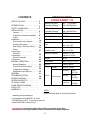
1
Hydro Smart 170
Micro Boiler for Radiant Heating
Installation Manual and Owner’s Guide
WARNING
This product must be installed and
serviced by a licensed plumber, a
licensed gas fitter, or a professional
service technician. This product is for
radiant heating only and must be
installed in with a combination of
Hydro
Panel
only.
Improper
installation
and/or
operation,
or
installation by an unqualified person,
will void the warranty.
WARNING
Hydro Smart 170
If the information in this manual is not
followed exactly, a fire or explosion may
result, causing property damage,
personal injury, or death.
Hydro Smart Contact Information
(Address, Phone Number)
Please make sure the proper gas pressure guidelines and recommendation from
Hydro Smart, failure to do so can cause a1fire or explosion and may result, causing
property damage, personal injury, or death.
CONTENTS
SPECIFICATIONS…………………….. 2
.
3
INTRODUCTION…………………….… 4
SAFETY GUIDELINES…………….….. 5
INSTALLATION……………………..…. 6
General…………………………….… 7
Warning for Location Installation … 8
Indoor
9
Installation…………………....
10
Direct Intake Vent System………….
17
Venting Instructions………………....
19
Gas Supply / Gas Pipe Sizing…...…
20
Water
21
Connections……………..……
Electrical
22
Connections……………....
22
Remote Controller
23
Connection…..…
NORMAL OPERATION…………..…… 24
Normal Operation…………………... 25
Freeze Protection System ………… 27
Temperature Settings ……………… 28
Maintenance and Service………….. 30
31
GENERAL
TROUBLESHOOTING……
34
WIRING DIAGRAM……………………. 36
OPERATING SAFETY…………………
OPTIONAL ITEMS……………………..
COMPONENTS DIAGRAM……………
PARTS LIST…………………………….
WARRANTY………….………………....
SPECIFICATIONS
HYDRO SMART 170
Natural Gas Input
(Operating Range)
Min: 11,000 Btu/h
Max: 199,000 Btu/h
LPG Input
(Operating Range)
Min: 11,000 Btu/h
Max: 199,000 Btu/h
Gas Connection
¾” NTP
Water Connections
¾” NTP
Water Pressure
15 - 150 psi*
Natural Gas Pressure
Inlet
Min. 5.0” WC
Max. 10.5” WC
LP Gas
Pressure Inlet
Min. 8.0” WC
Max. 14.0” WC
Manifold Pressure
Natural: 2.5” WC
Propane: 4.4” WC
Weight
40 lbs.
Dimensions
H20.5” x W13.8” x D8.5”
Ignition
Electric Ignition
Supply
Electric
Consumption
120VAC (60Hz)
Operation
92 W
(0.77A)
Standby
6.2 W
(0.05A)
FreezeProtection
111 W
(0.93A)
*40 psi or above is recommended for maximum flow
NOTE
*Check the rating plate to ensure this product
matches your specifications.
*In accordance with ANSI Z21.10.3 and
SCAQMD Rule 1146.2, CO emission does not
exceed 400 PPM for normal input
Hydro Smart reserves the right to discontinue, or change at any time,
specifications or designs without notice and without incurring obligations.
2
3
INTRODUCTION
•
This manual provides information necessary for the installation, operation, and
maintenance of the Hydro Smart 170 Micro Boiler.
•
The model description is listed on the rating plate which is attached to the front cover of
the micro boiler.
•
Please read all installation instructions completely before installing this product.
•
If you have any problems or questions regarding this equipment, consult with Hydro Smart
or its local representative.
•
•
Hydro Smart is a micro boiler designed to be used with radiant heating in a combination
Hydro Panel.
The principle behind the Hydro Smart 170 Micro Boiler is simple:
Hydro Smart 170 unit diagram/pictures
4
SAFETY GUIDELINES
•
Installation and service must be performed by a qualified installer (for
example, a licensed plumber or gas fitter), otherwise the warranty by Hydro
Smart will be void.
•
The installer (licensed professional) is responsible for the correct
installation of your Hydro Smart 170 Micro Boiler and for compliance with all
WARNING
national, state/provincial, and local codes.
PLEASE READ THIS MANUAL CAREFULLY AND FOLLOW ALL DIRECTIONS.
GENERAL
1.
Follow all local codes, or in the absence of local codes, follow the most recent edition of
the National Fuel Gas Code: ANSI Z223.1/NFPA 54 in the USA or CAN/CSA B149.1
Natural Gas, Propane Installation Code in Canada.
2.
Properly ground the unit in accordance with all local codes or in the absence of local
codes, with the National Electrical Codes: ANSI/NFPA 70 in the USA or CSA standard
C22.1 Canada Electrical Code Part 1 in Canada.
3.
Carefully plan where you intend to install your Hydro Smart 170 Micro Boiler. Please
ensure:
• Your micro boiler will have enough combustible air and proper
ventilation.
• Locate your micro boiler where water leakage will not damage
surrounding areas (please refer to p. 5).
4.
Check the rating plate for the correct GAS TYPE, GAS
PRESSURE, WATER PRESSURE and ELECTRIC RATING.
*If this unit does not match your requirements, do not install and
consult with Hydro Smart.
5.
If any problem should occur, turn off all hot water taps and turn off
the gas. Then call a trained technician or the Gas Company or the
RATING
manufacturer.
PLATE
WARNING
•
•
•
Prohibited
•
Do not store or use gasoline or other flammables, vapors, or liquids in the vicinity of this
appliance.
Do not reverse the water and/or gas connections as this will damage the gas valves
and can cause severe injury or death.
Do not use this appliance if any part has been in contact with or
been immersed in water. Immediately call a licensed plumber, a
licensed gas fitter, or a professional service technician to inspect
and/or service the unit if necessary.
Do not disconnect the electrical supply if the ambient temperature
will drop below freezing. The Freeze Prevention System only works if the unit has
electrical power. The warranty will not be covered if the heat exchanger is damaged
due to freezing. Refer to the section on the Freeze Prevention System on p. 22 for
more information.
5
INSTALLATION
All gas micro boilers require careful and correct installation to ensure safe and efficient
operation. This manual must be followed exactly. Read the “Safety Guidelines” section at the
beginning of this manual.
• The warranty will not cover damage caused by water quality. Water
hardness that leads to scale formation and/or corrosion may affect/damage
the micro boiler. Hard water scaling and/or corrosion must be avoided or
controlled by proper water treatment.
CAUTION
• HYDRO SMART recommends using the direct vent kit, when the micro
boiler is installed in a beauty salon. Some chemicals used in a beauty
salon may affect the flame sensor. Micro boiler may not work properly.
• Although the HYDRO SMART 170 is designed to operate with minimal
sound, HYDRO SMART does not recommend installing the unit on a
wall adjacent to a bedroom, or a room that is intended for quiet study
or meditation, etc.
• Locate your micro boiler close to a drain where water leakage will not do
damage to surrounding areas. As with any water heating appliance, the
potential for leakage at some time in the life of the product does exist.
Hydro Smart will not be responsible for any water damage that may occur.
If you install a drain pan under the unit, ensure that it will not restrict the
combustion air flow.
WARNING
• HYDRO SMART does not recommend installing unit in an attic due to
safety issues.
6
GENERAL
1. The manifold gas pressure is preset at the factory. It is computer controlled and should
not need adjustment.
2. Maintain proper space for servicing. Install the unit so that it can be connected or
removed easily. Refer to p. 7 and p. 8 for proper clearances.
3. The electrical connection requires a means of disconnection, to terminate power to the
micro boiler for servicing and safety purposes.
4. If you will be installing the unit in a contaminated area with a high level of dust, sand,
flour, aerosols or other contaminants/chemicals, they can become airborne and enter
and build up within the fan and burner causing damage to the unit. In those
environments (e.g. residential or commercial laundry facilities, hair salons, pet salons,
chemical plants etc.), please purchase the optional TK-TV10 direct vent conversion kit
and convert the HYDRO SMART 170 to a sealed combustion unit. Direct venting allows
the HYDRO SMART 170 to draw fresh intake air from the outside. The warranty will not
cover damage caused to the unit due to installation in a contaminated environment that
has not been converted using the TK-TV10.
5. Particles from flour, aerosols, and other contaminants may clog the air vent or reduce
the functions of the rotating fan and cause improper burning of the gas. Regularly ensure
that the area around the unit is dust- or debris-free; regular maintenance is
recommended for these types of environment.
6. Do not install the unit where the exhaust vent is pointing into any opening in a building or
where the noise may disturb your neighbors. Make sure the vent termination meets the
required distance by local code from any doorway or opening to prevent exhaust from
entering a building (refer to p. 13).
INCLUDED ACCESSORIES
Check that the installation manual and the warranty card are included with the unit.
Items
Manual
Qty: 1
Warranty Card
Qty: 1
7
WARNING FOR INSTALLATION LOCATIONS
Do not have the vent terminal pointing toward
any opening nto a building. Do not locate
your micro boiler in a pit or location where
gas and water can accumulate.
Do not install the micro boiler where water,
debris or flammable vapors may get into the
flue terminal. This may cause damage to the
micro boiler and void the warranty.
Prohibited
Prohibited
Do not install next to a dryer or any source of
airborne debris that can be trapped inside the
combustion chamber, unless the system is
direct vented.
Hydro Smart Installation Panel
Location Setting?
8
INDOOR INSTALLATION
1. Follow all local codes, or in the absence of local
codes, follow the most recent edition of the National
Fuel Gas Code: ANSI Z223.1/NFPA 54 in the USA
or CAN/CSA B149.1 Natural Gas, Propane
Installation Code in Canada.
Top 12”
2. When installed indoors, the HYDRO SMART 170
micro boiler shall be located in an area to maintain
the following minimum clearances around the unit:
Back 1”
Side 2”
Side 2”
Keep the clearances.
Front 4”
(24” Recommended
for Maintenance)
Bottom 12”
Combustion Air Supply
The micro boiler location must provide enough air for proper combustion and ventilation of the
surrounding area. See the latest edition of ANSI Standard Z223.1 or any applicable local codes.
In general, these requirements specify that if the unit is installed in a confined space, there must
be a permanent air supply opening.
Minimum recommended air supply opening size for micro boiler:
Micro boiler size
When drawing make-up air from When drawing make-up air from inside
outside the building
the building (from other rooms within)
MAX 199,000 BTU
13.3 Sq. IN
199 Sq. IN
When combustion air is supplied
from outside the building, an
opening communicating directly
with the outside should have a
minimum free area of one
square inch per 15,000 BTUH
input of the total input rating of
micro boiler in the enclosed
area.
When combustion air is supplied from
inside the building, an opening
communicating with the rest of the
dwelling should have a minimum free
area of one square inch per 1,000
BTUH input of the total input rating of
micro boiler in the enclosed area. This
opening should never be less than
199 sq. in.
Combustible Air Supplied by Mechanical fan or Make up air device
The HYDRO SMART 170 micro boiler is equipped with a combustible air sensor that will shut off
the unit when inadequate combustible air supply to unit is detected.
•
If a mechanical fan or make up air device is used to supply air to the micro boiler or
utility room, the installer should make sure it does not create drafts which could cause
nuisance shutdowns.
•
If a blower is necessary to provide adequate combustion air to the micro boiler, the
blower and micro boiler must be set up so that the micro boiler cannot fire unless the
blower is operating.
Possible methods include the use of external flow
sensors/transmitters and relays.
9
DIRECT INTAKE VENT SYSTEM
This HYDRO SMART 170 micro boiler may be converted to a direct vent (sealed combustion)
appliance by installing an adapter (Part No. TK-TV10) which will bring all required combustible
air from outside the building. When installing the TK-TV10 conversion kit, please follow all
instructions included with the kit.
•
The HYDRO SMART 170 must be installed in a location where the proper amount of
combustible air will be available to it at all times without obstructions.
•
If used as a direct vent appliance, the HYDRO SMART 170 requires a 3” combustible air
supply pipe. The intake pipe must be sealed airtight.
•
Air supply pipe can be made of ABS, PVC, galvanized steel, corrugated aluminum,
corrugated stainless steel or Category III stainless steel.
•
Change the dipswitch settings to the direct vent system. (See diagram below)
•
Sidewall venting is recommended for the direct vent system.
•
Hydro Smart recommends running the exhaust vent and the intake pipe parallel.
Make sure power to the unit is
turned OFF before changing
the dipswitch settings.
The dark square is the direction
the dipswitch should be set to.
Left bank of
dipswitches
7-Seg LED
Right bank of
dipswitches
Right Bank of Dipswitches
INLET
TK-TV10 Direct Vent
Conversion Kit
TK-TV10
DIRECT VENT
CONVERSION KIT
10
EXHAUST
VENTING INSTRUCTIONS
WARNING: Improper venting of this appliance can result in excessive levels of
carbon monoxide which can result in severe personal injury or death.
This micro boiler must be vented in accordance with the section “Venting of Equipment" of the
latest edition of the Natural Fuel Gas Code: The ANSI Z223.1, All applicable local building
codes, Section 7 of the CAN/CSA B149.1 Natural Gas in Canada, Propane Installation Code in
Canada.
EXHAUST VENT
This is a Category III appliance and must be vented accordingly. The vent system must be
sealed air tight. All seams and joints without gaskets must be sealed with high heat resistant
silicone sealant or UL listed aluminum adhesive tape having a minimum temperature rating of
350ºF. For best results, a vent system should be as short and straight as possible.
1.
This Hydro Smart micro boiler is a Category III appliance and must be vented accordingly
with any 4” vent approved for use with Category III or Special BH type gas vent.
2.
HYDRO SMART recommends the UL lister venting manufacturer as listed: Takagi
Industrial Co.USA, Inc. (T-Vent), ProTech Systems Inc. (FasNSeal), Flex-L Inc., Z-Flex
Inc. (Z-Vent III), Metal-Fab Inc., and Heat-Fab Inc. (Saf-T Vent).
3.
Follow the vent pipe manufacturer’s instructions when installing the vent pipe.
4.
Do not common vent this appliance with any other vented appliance (Do not
terminate vent into a chimney. If the vent must go through the chimney, the vent must run
all the way through the chimney with Category III approved or Special BH vent pipe).
5.
The maximum length of exhaust vent piping must not exceed 50 ft. deducting 5 ft. for each
elbow used in the venting system. Do not use more than 5 elbows.
Diameter
Max. No. of Elbow
Max. Vertical or Horizontal run in Length
4”
5 Ea.
50 ft.
*For each elbow added, deduct 5 ft. from max. Vent length.
No. of Elbows
0
1
2
5
Max. Vertical or Horizontal Length
50 ft.
45 ft.
40 ft.
25 ft.
6.
When the horizontal vent run exceeds 5 ft., support the vent run at 3 ft. intervals with
overhead hangars.
7.
Hydro Smart will not be responsible for any damage to the micro boiler caused by
condensation from the vent. Installing a condensate drip is recommended. Please refer to
p. 12 for the diagrams.
When installing the vent system, all applicable national and local codes must be
followed. If you install thimbles, fire stops or other protective devices and they
penetrate any combustible or noncombustible construction, be sure to follow all
applicable national and local codes.
11
VENT TERMINATION
WARNING: Improper installation can cause nausea or asphyxiation, severe injury
or death from carbon monoxide and flue gases poisoning. Improper installation
will void product warranty.
• The vent terminator provides a means of installing vent pipe through the building wall and
must be located in accordance with ANSI Z223.1/NFPA 54, or in Canada with CAN/CSAB149.1 and local applicable codes.
• A proper sidewall vent terminator is recommended when the micro boiler is vented through a
sidewall. If the HYDRO SMART 170 is converted to a direct-vent unit, a proper sidewall
direct-vent terminator is to be used.
General rules for venting the HYDRO SMART 170 micro boiler are:
1.
Place the micro boiler as close as possible to the vent terminator.
2.
The vent collar of the micro boiler must be fastened directly to an unobstructed vent pipe.
3.
Do not weld the vent pipe to the micro boiler collar.
4.
Do not cut the vent collar of the unit.
5.
The weight of the vent stack must not rest on the micro boiler.
6.
The vent must be easily removable from the top of the micro boiler for normal service and
inspection of the unit.
7.
The micro boiler vent must not be connected to any other gas appliance or vent stack.
8.
Avoid locating the micro boiler vent terminator near any air intake devices. These fans
can pick up the exhaust flue products from the micro boiler and return them to the building.
This can create a health hazard.
9.
Avoid using an oversized vent pipe or using extremely long runs of the pipe.
10. Locate the vent terminator so that it cannot be blocked by any debris, at any time. Most
codes require that the terminator be at least 12 inches above grade, but the installer may
determine if it should be higher depending on the job site condition and applicable codes.
11. For rooftop venting, a rain cap must be installed.
12. HYDRO SMART recommends the UL lister venting manufacturer as listed:
Takagi Industrial Co.USA, Inc. (T-Vent), ProTech Systems Inc. (FasNSeal), Flex-L
Inc., Z-Flex Inc. (Z-Vent III), Metal-Fab Inc., and Heat-Fab Inc. (Saf-T Vent).
12
Horizontal Installation Diagram
Wall
Vertical Condensation Drain
(Install according to local codes)
Sidewall
Vent
Terminator
TK-BF01 Backflow Preventor
(Recommended for freezing
weather conditions: 36°F and
below)
Rain Cap
Vertical Installation Diagram
Roof
Roof Flashing
TK-BF01 Backflow preventor
(Recommended for freezing
weather conditions: 36°F and
below)
Vertical Condensation Drain
(Install according to local codes)
• Regarding the clearance from the terminator to the air inlet or opening, refer to the next
page.
• Install a condensation drain in the venting.
• Follow the vent system to vent manufacturer’s instruction and local code.
• Do not common vent or connect any vent from other appliances to the HYDRO SMART 170
vent.
• Use 4” category III approved or Special BH, single or double wall stainless steel vent pipe.
13
VENT CLEARANCES
Canada
Direct vent and
other than Direct
Vent
U.S.A
Direct vent
Other than Direct Vent
1 foot
A
Clearance above grade, veranda, porch,
deck, or balcony.
1 foot
1 foot
B
Clearance to window or door that may be
opened.
3 feet
1 foot
4 feet from below or
side opening. 1 foot
from above opening.
*
Clearance to permanently closed window
*
*
Vertical clearance to ventilated soffit
located above the vent terminator within a
*
*
*
D
horizontal distance of 2 feet (61cm) from
the center line of the terminator.
*
*
*
E Clearance to unventilated soffit
*
*
*
F Clearance to outside corner
*
*
*
G Clearance to inside corner
Clearance to each side of center line
3 feet
*
*
H
extended above meter/regulator assembly
Clearance to service regulator vent outlet.
3 feet
*
*
I
Clearance to non-mechanical air supply
4 feet from below or
3 feet
1 foot
side opening. 1 foot
J inlet to building or the combustion air inlet
to any other application.
from above opening.
6 feet
3 feet
3 feet
K Clearance to mechanical air supply inlet.
Clearance above paved sidewalk or
7 feet
*
7 feet
L paved driveway located on public
property.
Clearance under veranda, porch deck, or
1 foot
*
*
M
balcony.
*For clearances not specified in ANSI Z223.1 / NFPA 54 or CAN/CSA-B149.1, please use clearances in
accordance with local installation codes and the requirement of the gas supplier.
C
14
ADDITIONAL CLEARANCES
Please follow all local and national codes in regards to proper termination clearances. In the
absence of such codes, the following clearances can be used as guidelines. Local codes
supersede these guidelines.
For sidewall terminations
2ft.
1ft.
1ft.
For multiple sidewall exhaust terminations (e.g.
multi-unit systems), an exhaust termination must
be at least 1 ft. away from another exhaust
termination. An exhaust termination must also be
at least 2 ft. away from an inside corner (if the
adjacent wall is less than 2 ft. of length, the
minimum required distance away from the inside
corner will be equal to the length of the wall).
Inside
corner
Exhaust termination
For direct-vent sidewall terminations that use two
separate penetrations for the intake and exhaust,
distance the intake and exhaust terminations at
least 3 ft. away from each other, no matter the
orientation.
3ft.
3ft.
3ft.
Air supply inlet
2ft.
1ft.
1ft.
Inside
corner
For multiple-unit, direct-vent sidewall terminations
that combine the intake and exhaust into a single
penetration, space each direct-vent termination at
least 1 ft. away from each other, no matter the
orientation. A direct-vent termination must also be
at least 2 ft. away from an inside corner (if the
adjacent wall is less than 2 ft. of length, the
minimum required distance away from the inside
corner will be equal to the length of the wall).
Direct vent
termination
15
2ft.
Exhaust and/or direct-vent
sidewall terminations should be at
least 2 ft. away from an opposite
surface/wall. Do not place the
termination directly in front of an
opening into a building.
Exhaust
termination
For rooftop terminations
A
A
2ft.
A
A
A
Air intake
Exhaust
termination
Exhaust
termination
Air intake
A: in accordance with local codes
For multiple-unit rooftop terminations (whether for standard indoor or direct-vent
installations) space all exhaust and intake terminations in accordance with local codes.
An exhaust termination must be spaced from a wall or surface in accordance with local
codes as well. In the absence of such a code, an exhaust termination must be a
horizontal distance of at least 2 ft. away from a wall or surface.
16
GAS SUPPLY AND GAS PIPE SIZING
TO TURN OFF GAS TO APPLIANCE
1. Turn off all electric power to the micro boiler if service is to be performed.
2. Turn the manual gas valve located on the outside of the unit clockwise 3 to the off position.
WARNING: Conversion of this unit from natural gas to propane or vise versa
cannot be done in the field. Contact your local distributor to get the correct unit for
your gas type. Conversion done by anyone other than the manufacturer will void all
warranty. Hydro Smart is not liable for any property and/or personal damage
resulting from unauthorized conversions.
*Check that the type of gas matches the rating plate first.
1.
The minimum and maximum inlet gas pressures are:
Natural Gas
Min. 5.0” WC - Max. 10.5” WC
Propane Gas
Min. 8.0” WC - Max. 14.0” WC
2.
Gas pressure below this specified range for the HYDRO SMART 170 and/or insufficient gas volume
will adversely affect performance. These pressures are measured when the HYDRO SMART 170 is
in full operation.
3.
Inlet gas pressure must not exceed the above maximum values; gas pressure above the specified
range will cause dangerous operating conditions and damage to the unit. Ensure that any and all
gas regulators used are operating properly and are providing gas pressures within the specified
range shown above.
4.
Until testing of the main gas line supply pressure is completed, ensure the gas line to the HYDRO
SMART 170 is disconnected to avoid any damage to the micro boiler.
MEASURING INLET GAS PRESSURE
The HYDRO SMART 170 cannot perform properly without sufficient inlet gas pressure. Below are
instructions on how to check the inlet gas pressure. THIS IS ONLY TO BE DONE BY A LICENSED
PROFESSIONAL.
1.
Shut off the manual gas valve on the supply gas line.
2.
Open a faucet. The unit should turn on and the gas in the
gas pipe line should purge. Leave the faucet on to keep the
unit running until the unit shut down due to lack of gas
supply. Then shut the faucet off.
3.
Remove the screw for the pressure port located on the gas
inlet of the HYDRO SMART 170 shown in the diagram to
the right.
4.
Connect the manometer to the pressure port.
5.
Re-open the manual gas valve. Check to see that there are
no gas leaks.
6.
Open some of the fixtures that use the highest flow rate to
turn on the HYDRO SMART 170.
7.
Check the inlet gas pressure. When HYDRO SMART 170
is on a maximum burn, the manometer should read from 5.0” to 10.5” WC for Natural gas, from 8.0”
to 14.0” WC for Liquid Propane.
17
Size the gas pipe appropriately to supply the necessary volume of gas required
for the HYDRO SMART 170 (199,000 BTUH for both Natural Gas and Liquid
Propane) using ANSI233.1/NAPA 54 in the USA or CAN/CSA B149.1 in Canada
or local codes. Otherwise, flow capabilities and output temperatures will be
limited.
1.
Install a manual gas shut-off valve between the HYDRO SMART 170 and the gas supply
line.
2.
When the gas connections are completed, it is necessary to perform a gas leak test either
by applying soapy water to all gas fittings and observing for bubbles or by using a gas leak
detection device.
3.
Always purge the gas line of any debris and/or water before connecting to the gas inlet.
Natural Gas Supply Piping
Maximum Delivery Capacity of Cubic Feet of Gas per Hour of IPS Pipe Carrying Natural Gas of 0.60 Specific Gravity
Based on Pressure Drop of 0.5” WC
Based on Energy Content of 1000 BTU/Cubic Ft.: HYDRO SMART 170 requires 199 Cubic Ft./hr.
Unit: Cubic Feet per Hour
Pipe Size
inches
¾”
1”
1 ¼”
1 ½”
2”
Length in Feet
10’
20’
30’
40’
50’
60’
70’
80’
90’
100’ 125’ 150’
363
249
200
171
152
138
127
118
111
104
93
84
684
470
377
323
286
259
239
222
208
197
174 158
1404 965
775
663
588
532
490
456
428
404
358 324
2103 1445 1161 993
880
798
734
683
641
605
536 486
4050 2784 2235 1913 1696 1536 1413 1315 1234 1165 1033 936
200’
72
135
278
416
801
Propane (LP) Gas Supply Piping
Maximum Capacity of Propane (LP) Gas Based on 11” WC supply pressure at a 1.0” WC pressure drop
Unit: kBTU per Hour
Pipe Size
inches
¾”
1”
1 ¼”
1 ½”
2”
Length in Feet
10’
20’
30’
40’
50’
60’
70’
80’
90’
100’ 125’ 150’ 200’
567
393
315
267
237
217
196
185
173
162
146
132
112
1071 732
590
504
448
409
378
346
322
307
275
252
213
2205 1496 1212 1039 913
834
771
724
677
630
567
511
440
3307 2299 1858 1559 1417 1275 1181 1086 1023 976
866
787
675
6221 4331 3465 2992 2646 2394 2205 2047 1921 1811 1606 1496 1260
Gas Sizing Example
(Natural Gas)
Hydro
Smart 170
199,000BTU
5’ Length
1-1/4” Pipe Size A
Divide each appliance’s BTU requirement by 1000BTU to get
the appliances Cubic Ft. requirement.
Take into the distance the appliance is from the gas meter, look
in the above gas chart to properly size the line.
Dryer
35,000BTU
10’ Length
3/4” Pipe Size
B
10’ Length
5’ Length
1” Pipe Size
1-1/4” Pipe Size
Gas Meter
Based on Energy Content of 1000BTU/Cubic Ft:
10’ Length
1/2” Pipe Size
15’ Length
1” Pipe Size
C
10’ Length
3/4” Pipe Size
Furnace
120,000BTU
15’ Length
1/2” Pipe Size
Range
65,000BTU
18
For sections of the gas line supplying gas to more than one
appliance (Ex: Point A to Point B), add up the cubic ft.
requirements of the appliances that are being supplied by that
section, and size to the farthest appliance.
For Example: The section from A to B supplies gas to the
furnace, range, and dryer. Adding up the BTU requirements and
dividing by 1000 yields a cubic ft. requirement of 220 cubic ft. of
gas. The farthest appliance is the range, which is 50 ft. away
from the meter. Looking at the above chart, and under the
column of 50ft., Section A to B needs to be 1” in order to supply
220 cubic ft.
WATER CONNECTIONS
FOR YOUR SAFETY, READ BEFORE OPERATING:
Do not use this micro boiler if any part has been submersed under water. Immediately
call a licensed professional to inspect the micro boiler and to replace any damaged
parts.
1.
All pipes, pipe fittings, valves and other components, including soldering materials, must
be suitable for potable water systems.
2.
A manual shut off valve must be installed on the cold water inlet to the micro boiler
between the main water supply line and the HYDRO SMART 170.
3.
In addition, a manual shut off valve is also recommended on the hot water outlet of the
unit. If the HYDRO SMART 170 is installed within, or subjected to, a closed loop water
system, a thermal expansion tank must be installed.
4.
Before installing the micro boiler, flush the water line to remove all debris, and after
installation is complete, purge the air from the line. Failure to do so may cause
damage to the micro boiler.
5.
There is a wire mesh filter within the cold inlet to trap debris from entering your micro
boiler. This will need to be cleaned periodically to maintain optimum flow.
CAUTION: Do not reverse the hot outlet and cold inlet connections to the
HYDRO SMART 170 Micro boiler. This will not properly activate the micro
boiler.
19
ELECTRICAL CONNECTIONS
WARNING: Follow the electrical code requirements of the local authority having
jurisdiction. In the absence of such requirements, follow the latest edition of the
National Electrical Code ANSI/NFPA 70 in the U.S. or the latest edition of CSA
C22.1 Canadian Electrical Code, Part 1, in Canada.
CAUTION: When servicing or replacing parts within the HYDRO SMART 170 label all wires
prior to disconnection to facilitate an easy and error-free reconnection. Wiring errors can
cause improper and dangerous operation. Verify proper operation after servicing.
1.
The micro boiler must be electrically grounded. Do not attach the ground wire to either
the gas or the water piping.
2.
The HYDRO SMART 170 micro boiler requires AC 120V 60 Hz electrical power supply
that is properly grounded.
• A proper disconnect (i.e. on/off switch, power plug, etc.) controlling the main power to
the HYDRO SMART 170 must be provided for service reasons. (Must comply with
local codes).
• Connect the power supply to the HYDRO SMART 170 exactly as shown in the wiring
diagram;
3.
A green screw is provided in the junction box to ground the connection.
4.
Can be hardwired or wired to a plug-in.
5.
The use of a surge protector is recommended in order to protect the unit from power
surges.
Connect Power supply
AC120V 60Hz
Ground
20
REMOTE CONTROLLER CONNECTION
1) Disconnect power supply from the HYDRO SMART 170.
2) Take off the HYDRO SMART 170’s front cover.
3) Please find the remote control terminal using the picture below (located around the lower
right-hand side of the computer board).
4) Open the plastic cover of the TM-RE30, and then attach the fork terminal to the connector
base of the backside the TM-RE30 with two screws. Make sure the terminals are firmly fixed.
5) Put the remote wires through the hole on the bottom of the unit casing.
6) Connect the remote wires to the remote controller terminal properly. (No polarity)
*Do NOT jump or short-circuit wires. Computer will be damaged.
7) Replace Front Cover securely.
8) Wires used for the remote controller connection must be:
• Minimum 18AWG wire (No polarity)
• Maximum 400 feet long
*For details on the connection to the TM-RE30, refer to the TM-RE30’s Installation Manual.
Remote controller terminal inside Hydro Smart 170
Front of remote
Back of remote
Connect to these terminals
Connect other end to these terminals
21
NORMAL OPERATION
WITH REMOTE CONTROLLER INSTALLED: TM-RE30 (Optional)
*If the TM-RE10 is used, refer to the TM-RE10 Installation Manual included with the remote.
1. Press the power ON/OFF button.
2. Set temperature. (Example 110°F)
When ON,
green LED is lit.
The temperature and the
time will be displayed on
the remote controller.
Temperatures available under the Default Mode
99
100
102
104
106
108
110
111
113
115
117
122
131
140
158
131
140
149
158
167
167
Temperatures available under the High Temperature Mode
99
100
102
104
106
108
110
111
113
122
176/185
(unit:°F)
• DO NOT set to 185 °F if you use your Hydro Smart 170 in recirculation system. (?) REMOVE?
• Refer to the TM-RE30 Installation Manual to change the setting to the High Temperature mode.
We’d like to remove High Temperature Mode (by Ichikawa)
FREEZE PROTECTION SYSTEM
• This unit comes equipped with heating blocks to protect it against damages associated with
freezing.
• For this freeze protection system to operate there has to be electrical power to the unit.
Damage to the heat exchanger caused by freezing temperatures due to power loss is not
covered under the warranty. In cases where power losses can occur, consider the use of a
backup power supply.
• The freeze protection system will activate when the surrounding and/or outside temperatures
drop below 36.5°F (2.5°C).
• In any areas subject to freezing temperatures, Hydro Smart highly recommends installing the
unit indoors. In such an installation, freezing issues can only occur if cold air enters through
the venting into the heat exchanger, whether by negative pressures within the installation
location or by strong outside winds. It is the installer’s responsibility to be aware of these
issues and take all preventative measures. Hydro Smart will not be responsible for any
damage to the heat exchanger as a result of freezing.
• Hydro Smart also highly recommends the use of a back flow vent damper and/or converting
the HYDRO SMART 170 to a direct-vent unit to minimize the amount of cold air entering
through the exhaust venting when the micro boiler is off.
• If you will not be using your micro boiler for a long period of time:
1. Completely drain the unit of water. Refer to p. 24
2. Disconnect power to your micro boiler.
This will keep your unit from freezing and being damaged.
22
CAUTION: Only pipes within the micro boiler are protected by the freeze protection system.
Any water pipes (hot or cold) located outside the unit will not be protected. Properly protect
and insulate these pipes from freezing.
23
TEMPERATURE SETTINGS
• Temperature Dipswitch setting has to be set per Hydro Smart Specifications.
• There are 8 preset temperatures that you can select from by changing the dipswitch settings
on the computer board.
• The temperature has been preset at the factory to 122ºF (50ºC). Setting temperature over
160 ºF will void the warranty? (See Ichikawa-san and Paul e-mail?)
• If you desire to change the set temperature with dipswitches, please refer to the diagram on
below. These temperatures are available: 104ºF, 113ºF, 122ºF, 131ºF, 140ºF, 158ºF, 176ºF,
and 185ºF. (?)
• 140ºF, 158ºF, 176ºF and 185ºF are for heating applications only.
• If you desire a hot water temperature other than the 8 preset settings, please purchase the
optional temperature remote controller (part No. TM-RE30).
• With this optional TM-RE30 you can set the temperature from 99ºF to 176ºF with various
increments.
• Please read the instructions carefully prior to installing the TM-RE30, as failure to do so
could damage the temperature controller and/or the micro boiler, which will void the
warranty.
• Turn off the power supply to the micro boiler before changing the dipswitch
settings.
• Only change the switches with the dark squares. The dark squares indicate
which direction the dipswitch should be set to.
• DO NOT set to 185 ºF if you use your HYDRO SMART 170 in a recirculation
system. This will cause damage to the micro boiler and void the warranty.
Left bank of
dipswitches
To change dipswitch settings for
temperatures, locate the right
bank of dipswitches the above of
7-seg LED.
DO NOT adjust the left bank of
dipswitches.
7-Seg
Right bank
of
Temperature settings <Right bank of dipswitches>
The
Thedark
darksquares
squaresindicate
indicatethe
thedirection
direction
the
thedipswitches
dipswitchesshould
shouldbe
beset
setto.
to.
Temperature Settings <Right bank of dipswitches>
24
MAINTENANCE AND SERVICE
WARNING: Turn off the electrical power supply and close the manual gas
control valve and the manual water control valve before servicing.
• Clean the water filter attached on Hydro Smart Heating Panels.
• Be sure that all openings for combustion and ventilation air are not blocked.
• Check that the exhaust vent pipe is not blocked.
• Check the gas pressure.
• Keep the area around the micro boiler clear. Remove any combustible materials, gasoline or
any flammable vapors and liquids.
HYDRO SMART recommends having the unit checked once a year or as necessary by a
licensed technician. If repairs are needed, any repairs should be done by a licensed technician.
UNIT DRAINING FOR MAINTENANCE
1. Close the manual gas shut off valve.
2. Turn off power to the unit, and then turn on again.
3. Wait 30 seconds, and then turn off power to the
unit, yet again.
4. Close the water shut off valve.
5. Open all hot water taps in the house. When the
residual water flow has ceased, close all hot
water taps. (??)
6. Have a bucket or pan to catch the water from the
unit’s drain plugs. Unscrew the drain plugs to
drain all the water out of the unit.
7. Wait a few minutes to ensure all water has
completely drained from unit.
25
Gas Valve
GENERAL TROUBLESHOOTING
~ MICRO BOILER ~
PROBLEM
POSSIBLE SOLUTIONS
Unit does not ignite when water goes
through the unit.
• Is the flow rate over 0.5 GPM? (p. 28)
• Check for the Hydro Smart Y Strainer on cold water
inlet.
• Check for reverse connection and cross connection.
• If you use the remote controller, is the power button
turned on? (p. 28)
The fan motor is still spinning after
operation has stopped.
• This is normal. After operation has stopped, the fan
motor keeps running from 5 to 50 seconds in order
to re-ignite quickly, as well as purge all the exhaust
gas out of the flue.
Abnormal sounds come from the unit . • Contact HYDRO SMART.
~ REMOTE CONTROLLER: TM-RE30 (OPTIONAL) ~
PROBLEM
Remote controller does not display
anything when the power button is
turned on.
POSSIBLE SOLUTIONS
Press the ON/OFF button.
If the lamp lights up ⇒
• This is normal. When the unit has not operated for
five minutes or more, the display turns off to
converse energy.
If the lamp does not light ⇒
• Make sure the unit has power supply.
• Make sure the connection to the unit is correct.(p. 21)
An ERROR code is displayed.
• Please see p. 26.
26
TROUBLESHOOTING – ERROR CODES
•
•
All Hydro Smart units are self diagnostic for safety and convenience when trouble shooting.
If there is a problem with the installation or the unit, it will display a numerical error code on the
TM-RE30 (if installed) or on the 7-Seg LED at the bottom left corner of the computer board to
communicate the source of the problem.
•
Consult the following chart for the cause of each error code.
7-Seg LED
TM-RE30 (Optional)
Error
Code
Malfunction description
Error
Code
031
Dipswitch setting fault
331
101
Warning for 991 Error
Code
391
111
Ignition Failure
441
121
Flame blows out
510
311
Output Thermistor Failure
611
321
Inlet Thermistor Failure
651
Malfunction description
Mixing Thermistor
Failure
Air-fuel Ratio Rod
Failure
Flow Sensor Failure
Abnormal Main and
Solenoid Gas Valve
Fan Motor Fault
Flow Adjustment Valve
Fault
Single Unit
• The 7-Seg LED displays the 3-digit error codes one
digit at a time. The TM-RE30 (if installed) displays
the whole 3-digit error code at once.
Example:
If your unit has the “321” error code (inlet thermistor),
• The 7-Seg LED, will flash the 3-digit error code one
digit at a time. The 7-Seg LED will display “3”...
“2”... “1”, and then repeat the 3 digits.
• The remote controller, however, will display “321”
on its screen, in its entirety.
27
Error
Code
Malfunction description
701
Computer board Fault
721
False Flame Detection
741
761
991
Miscommunication
between HYDRO
SMART 170/HYDRO
SMART 170-Pro and
TM-RE30
Miscommunication in
Easy-link
Abnormal burning
WIRING DIAGRAM
A wiring diagram is located on the inside front panel of the appliance.
Electrical Rating: 120 VAC, 60 Hz
Note: If any of the original wiring supplied with this appliance must be replaced, it must be replaced with
appliance wiring material (180c) or its equivalent. Replacement wires are available through Hydro
Smart.
W
White
R
Red
G
Green
Black
Y
Yellow
Purple
O
Orange
BK
P
LB
BL
Light blue
FM
3A
Blue
BR
Transformer
BK
W
AC120V
BK
W
Ground
G
BR
BR
Brown
BR
BR
G
R
Ground
BL
Y
O
W
BK
W
Proportional
Valve
W
W
R
R
Heater
BK
33
Flow
Sensor
BK
BK
R
R
W
W
GFI
7
Heater
BK
P
P
P
P
7
Freeze
protection
thermostat
IG
Elect rod
AFR rod
Y
G
O
Ground
Flow
Adjust
ment
Valve
3
Flame rod
BL
BL
9
R
R
BK
R
R
BK
BK
MV
BL
BL
53
BK
Hilimit
switch
BL
BL
SV1
O.H.C.F
BL
LB
G
O
R
73
SV2
SV3
Bypass
Valve
SLAVE IN
BK
W
Multi-system
On line lamp
Pump
BK
BK
BK
BK
MIN button
Decrease button
123456
MASTER
Mixing
thermistor
BK
Output
thermistor
123456
BK
Burning lamp
7 Seg LED
W
BK
OF F
OFF
Error call button
SLAVE OUT
Dip switch
MAX button
Increase button
W
BK
Remote
Controller
28
Inlet
thermistor
BK
OPERATING SAFETY
FOR YOUR SAFETY READ BEFORE OPERATING
WARNING: If you do not follow these instructions exactly, a fire or explosion may
result causing property damage, personal injury or loss of life.
A. This micro boiler does not have a pilot. It is equipped with an ignition device that
automatically lights the burner. Do not try to light the burner by hand.
B. BEFORE OPERATING smell all around the micro boiler area for evidence of leaking
gas. Be sure to smell next to the floor because some gas is heavier than air and will
settle on the floor.
WHAT TO DO IF YOU SMELL GAS.
• Do not try to light any appliance.
• Do not touch any electric switch, do not use any phone in your building.
• Immediately call your gas supplier from a neighbor's phone. Follow the gas
supplier's instructions.
• If you cannot reach your gas supplier, call the fire department.
C. Use only your hand to turn the gas valve knob. Never use tools. If the knob will not
turn by hand, don't try to repair it. Call a qualified service technician. Forced or
attempted repair may result in a fire of explosion.
D. Do not use this micro boiler if any part has been under water. Immediately call a
qualified service technician to inspect the micro boiler and to replace any damaged
parts.
OPERATING INSTRUCTIONS
1. STOP! Read the safety information above or in the Owners Manual.
2. Turn off all electric power to the micro boiler.
3. Do not attempt to light the burner by hand.
4. Turn the manual gas valve located on the outside of the unit clockwise ↻ to the off
position.
5. Wait five (5) minutes to clear out any gas. If you then smell gas. STOP! Follow "B" in
the safety information above on this label. If you don't smell gas, go to next step.
6. Turn the manual gas valve located on the outside of the unit counter clockwise ↺ to
the ON position.
7. Turn on all electrical power to the micro boiler.
8. If the micro boiler will not operate, follow the instructions “to Turn Off Gas to micro
boiler" and Call your service technician or gas supplier.
TO TURN OFF GAS TO APPLIANCE
1. Turn off all electric power to the micro boiler if service is to be performed.
2. Turn the manual gas valve located on the outside of the unit clockwise ↻ to the off
position.
29
DANGER
Vapors from flammable liquids will explode and catch fire causing death or severe burns.
Do not use or store flammable products such as gasoline, solvents or adhesives in the same
room or area near the micro boiler.
Keep flammable products:
1. Far away from micro boiler.
2. In approved containers.
3. Tightly closed
4. Out of children's reach
Vapors:
1. Cannot be seen
2. Vapors are heavier than air
3. Go a long way on the floor
4. Can be carried from other rooms to the
main burner by air currents
WARNING: Do not install micro boiler where flammable products will be stored.
Read and follow micro boiler warnings and instructions. If owner’s manual is missing,
contact the retailer or manufacturer.
WARNING
California Proposition 65 lists chemical substances known to the state to cause cancer, birth
defects, death, serious illness or other reproductive harm. This product may contain such
substances, be their origin from fuel combustion (gas, oil) or components of the product itself.
30
OPTIONAL ITEMS
1. TM-RE30 Temperature Remote Controller
The TM-RE30 Temperature
Remote Controller has two
functions. It allows the output
temperature from the HYDRO
SMART 170 to be adjusted within
the range of 99 °F to 185 °F, and
it also works as a diagnostic tool that will give a
concise error code whenever there is a problem
with the unit. The temperature options are 99°F,
100°F, 102°F, 104°F, 106°F, 108°F, 110°F, 111°F,
113°F, 115°F, 117°F, 122°F, 131°F, 140°F, 149°F,
158°F, 167°F, 176°F and 185°F. See the trouble
shooting section for information on possible error
codes.
3. TK-TV10 Direct venting kit
2. TK-BF01 Backflow preventer
The
TK-BF01
Backflow
preventer prevents the backflow
of air through the exhaust vent.
This helps prevent harmful
exhaust gases from entering the
home, as well as helping to
prevent the unit from freezing in areas where
cold air can be blown or drawn into the
exhaust system. Install this vent damper in
accordance with Hydro Smart’s installation
instructions, and any applicable codes.
This kit can be used convert the HYDRO SMART 170 from a
conventional vent system to a direct vent (or sealed combustion)
system. This is a CSA tested conversion kit. Install this conversion kit
in accordance with Hydro Smart’s installation instructions and any
applicable codes.
4. TK-KPWL4 and TK-KPWH4 T-Vent Wall thimble with Termination
These terminations are used when venting out through the wall and
are compatible with the T-Vent pipe system.
These terminations are special stainless steel vents for gas
appliances and are UL listed as Category II, III and IV. There are
two types of terminations: the Louver termination and the Hood
termination. For different wall thicknesses, there are 3 ranges of
TK-KPWH4 lengths available (refer to the T-Vent brochure for details).
TK-KPWL4
Install these vent terminations in accordance with Hydro Smart’s
Hood
Louver
installation
instructions and any applicable local codes.
Termination
Termination
31
COMPONENTS DIAGRAM
Case assembly
052
050
002
006
052
051
051
004
052
003
001
051
706
707
053
050
007
702
054
052
053
005
052
Computer board assembly
104
701
709
714
710
708
715
716
711
717
712
32
Burner assembly
401
115
112
107
124
114
151
117
101
106
716
118
151
156
116
119
111
157
110
703
121
151
103
151
150
120
150
104
705
125
123
150
711
153
718
150
150
709
152
122
113
158
159
720
710
704
152
154
150
155
054
33
719
154
108
052
Water way assembly
410
415
411
459
452
403
451
409
412
413
401
414
456
460
454
407
402
458
412
457
454
452
458
454
458
404
416
453
417
405
052
456
418
408
450
455
420
T-K3-Pro
Heat Exchanger
34
419
052
450
406
456
PARTS LIST
ther than the front cover (No.7) and heat exchanger assembly (No.420), all of the T-K3-Pro’s
components are the same as the T-K3.
Item#
Part#
Description
Item#
Part#
Description
1
EKK1D
Case assembly
122
EKK1B
Igniter plate
2
EKK1J
Front cover
123
EM167
Wire clamp 60
3
EKJ62
Air blockage plate
124
EKK2X
Burner gasket
4
EKJ09
Bracket
125
EKK2K
Manifold gasket B
5
EKJ64
Junction box
150
EW003
Screw M4×10
6
EKK5H
Back guard panel
151
EW002
Screw M4×10 (Coated)
EKK37
Screw M4×12
7
EK320
Front cover (REMOVE)
152
50
EW000
Screw M4×12
153
EW004
Hex head screw M4×12
51
EW001
Screw M4×10 (W/Washer)
154
EW005
Hex head screw M4×8
52
EW002
Screw M4×10 (Coated)
155
EW006
Pan screw M4×10
53
EW003
Screw M4×10
156
EW00B
Screw M3×8
54
EC00X
Nylon clamp
157
EW008
Screw M3×10
101
EKK1N
Burner assembly
158
EK042
O-ring P20 NBR
EKK1S
Manifold assembly with gas
valve assembly LP
159
EZP18
O-ring P18 NBR
EKK1T
Manifold assembly with gas
valve assembly NA
401
EKK1X
104
EKK25
Fan motor
402
EKK0T
Flow adjustment valve/ Flow
sensor
106
EKK0E
Flame rod
403
EKK0U
Bypass valve
107
EKK0F
Igniter rod
404
EKK1U
Water inlet
108
EKK1E
Gas inlet
405
EKK1V
Water outlet
110
EKK1P
Damper
406
EKK38
Inlet thermistor
111
EK270
Fan damper
407
EKK2T
Output thermistor
112
EKN61
Rod cap
408
EKK1A
Mixing thermistor
113
EKK2Z
Gas inlet ring
409
EKN34
Hi-Limit switch
114
EKK2V
Burner window
410
EKN50
Silicon ring
115
EKK2W
Rod holder gasket
411
EK333
Over heat cut off fuse
116
EKK32
Rod holder
412
EKK2R
Micro boiler
117
EKK0G
Burner holder gasket
413
EKK27
Pipe micro boiler fixing plate
118
EKK2D
Pressure port
414
EKK26
Fuse fixing plate 18
119
EKK2N
Urethane tube
415
EK029
Fuse fixing plate 14
120
EKK2Y
Manifold gasket A
416
EKK2B
Inlet drain plug
121
EKK20
GFI plate
417
EKK2C
Inlet water filter
103
35
Heat exchanger assembly
Item#
Part#
Description
Item#
Part#
Description
418
EKK2P
Inlet micro boiler
705
EKJ59
Freeze protection thermostat
419
EKK2E
Outlet drain plug
706
EKN37
Fuse assembly
420
EK322
Heat exchanger assembly
for HYDRO SMART 170-Pro
707
EKJ66
Junction box inner plate
450
EW009
Screw M4×6
708
EKK1M
Computer board cover
451
EW00A
Screw M4×3
709
EKK0D
AC100V wire
452
EZM16
O-ring P16 EPDM
710
EKK0Z
EH-IG Wire
453
EZM15
O-ring P15 EPDM
711
EKK10
Gas valve wire
454
EZM14
O-ring P14 EPDM
712
EKK36
Pump and multi cable
455
EZM06
O-ring P6 EPDM
714
EKK35
RS-VG wire
456
EZM04
O-ring P4 EPDM
715
EKK33
Water valves wire
457
EM192
Fastener “16A”
716
EKK11
Flame rod wire
458
EKK24
Fastener “14-22”
717
EKK1Z
Thermistors wire
459
EKK39
Fastener “16-25A”
718
EKK0B
Transformer wire
460
EKH30
Fastener “4-11”
719
EKK12
Proportional gas valve wire
701
EKK1L
Computer board
720
EKK2M
High voltage igniter wire
702
EKH09
Transformer
703
EKN73
Ground fault circuit interrupter
704
EKN74
Igniter
36
11.
37