1
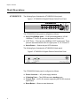
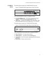
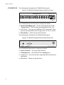
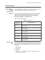
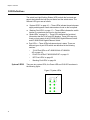
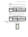
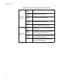
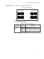
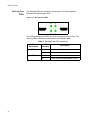
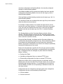
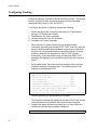
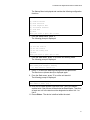
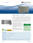
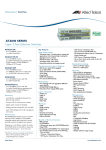
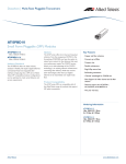
AT-8000GS Series Stackable Gigabit Ethernet Switches AT-8000GS/24 AT-8000GS/POE AT-8000GS/48 Installation Guide 613-000974 Rev. D Copyright © 2010 Allied Telesis, Inc. All rights reserved. No part of this publication may be reproduced without prior written permission from Allied Telesis, Inc. Allied Telesis and the Allied Telesis logo are trademarks of Allied Telesis, Incorporated. All other product names, company names, logos or other designations mentioned herein are trademarks or registered trademarks of their respective owners AT-8000GS Series Gigabit Ethernet Switch Installation Guide Preface This guide provides the hardware installation instructions for your managed, AT-8000GS Series Gigabit Ethernet switch. This preface contains the following sections: “Safety Symbols Used in this Document” on page 4 “Where to Find Web-based Guides” on page 5 “Contacting Allied Telesis” on page 6 3 Preface Safety Symbols Used in this Document This document uses the safety symbols defined in Table 1. Table 1. Safety Symbols Symbol 4 Meaning Description Caution Performing or omitting a specific action may result in equipment damage or loss of data. Warning Performing or omitting a specific action may result in electrical shock. AT-8000GS Series Gigabit Ethernet Switch Installation Guide Where to Find Web-based Guides The product documentation for all Allied Telesis products are available in portable document format (PDF) on our web site. Go to http://www.alliedtelesis.com/support/software/. Enter your hardware product model in the Search by Product Name field; for example, enter AT-8000GS/24. You can view the documents online or download them onto your local workstation or server. 5 Preface Contacting Allied Telesis This section provides Allied Telesis contact information for technical support as well as sales and corporate information. Online Support You can request technical support online by accessing the Allied Telesis Knowledge Base: www.alliedtelesis.com/support/kb.aspx. You can use the Knowledge Base to submit questions to our technical support staff and review answers to previously asked questions. Email and Telephone Support For Technical Support via email or telephone, refer to the Support & Services section of the Allied Telesis web site: www.alliedtelesis.com. Select your country from the list displayed on the website. then select the appropriate menu tab. Returning Products Products for return or repair must first be assigned a return materials authorization (RMA) number. A product sent to Allied Telesis without an RMA number will be returned to the sender at the sender’s expense. To obtain an RMA number, contact the Allied Telesis Technical Support group at our web site: www.alliedtelesis.com/support/rma. Select your country from the list displayed on the website. Then select the appropriate menu tab. Sales or Corporate Information Warranty Management Software Updates You can contact Allied Telesis for sales or corporate information through our web site: www.alliedtelesis.com. To find the contact information for your country, select Contact Us -> Worldwide Contacts. Go to www.alliedtelesis.com/support/warranty for specific terms and conditions of the warranty and for warranty registration for your AT-8000GS switch. The product documentation for all Allied Telesis products are available in portable document format (PDF) on our web site. Go to http://www.alliedtelesis.com/support/software/. Enter your hardware product model in the Search by Product Name field; for example, enter ATƒS750/24. You can view the documents online or download them onto your local workstation or server. 6 Content Preface ..................................................................................................................................................................................3 Safety Symbols Used in this Document..................................................................................................................................4 Where to Find Web-based Guides .........................................................................................................................................5 Contacting Allied Telesis ........................................................................................................................................................6 Online Support ................................................................................................................................................................6 Email and Telephone Support .........................................................................................................................................6 Returning Products..........................................................................................................................................................6 Sales or Corporate Information .......................................................................................................................................6 Warranty ..........................................................................................................................................................................6 Management Software Updates ......................................................................................................................................6 Chapter 1: Overview ............................................................................................................................................................9 AT-8000GS Switch Series Features.....................................................................................................................................10 IEEE Standards ....................................................................................................................................................................11 Model Descriptions ...............................................................................................................................................................12 AT-8000GS/24 ..............................................................................................................................................................12 AT-8000GS/24POE .......................................................................................................................................................13 AT-8000GS/48 ..............................................................................................................................................................14 Port Descriptions ..................................................................................................................................................................15 10/100/1000 Base-T Gigabit Ethernet Ports .................................................................................................................15 SFP Port ........................................................................................................................................................................15 RJ-45 Console Port .......................................................................................................................................................15 LED Definitions .....................................................................................................................................................................16 System LEDS ................................................................................................................................................................16 Stacking Port LEDs .......................................................................................................................................................17 Mode LEDs....................................................................................................................................................................18 RJ-45 Port LEDs on AT-8000GS/24 & AT-8000GS/48 .................................................................................................19 RJ-45 Port LEDs AT-8000GS/24POE ...........................................................................................................................21 SFP Port LEDs ..............................................................................................................................................................23 Stacking Port LEDs .......................................................................................................................................................24 Chapter 2: Installation .......................................................................................................................................................25 Reviewing Safety Precautions ..............................................................................................................................................26 Preparing for Installation.......................................................................................................................................................29 Installation Precautions .................................................................................................................................................29 Site Requirements .........................................................................................................................................................29 Unpacking .....................................................................................................................................................................30 Installing the Device .............................................................................................................................................................31 Desktop or Shelf Installation..........................................................................................................................................31 Rack Installation ............................................................................................................................................................31 Connecting the Device .........................................................................................................................................................33 Connecting the Switch to a Terminal.............................................................................................................................33 AC Power Connection ...................................................................................................................................................33 Chapter 3: Stacking ...........................................................................................................................................................35 Stacking Overview ................................................................................................................................................................36 Stacking Ring Topology ................................................................................................................................................36 Stacking Chain Topology ..............................................................................................................................................37 Stacking Members and Unit ID......................................................................................................................................37 Removing and Replacing Stacking Members................................................................................................................37 Exchanging Stacking Members .....................................................................................................................................39 Configuring Stacking ............................................................................................................................................................40 7 Contents Chapter 4: Initial Configuration ........................................................................................................................................43 Configuration Overview.........................................................................................................................................................44 Configuration ........................................................................................................................................................................45 Static IP Address and Subnet Mask ..............................................................................................................................45 User Name ....................................................................................................................................................................46 Chapter 5: Troubleshooting ..............................................................................................................................................47 Device not operating correctly .......................................................................................................................................47 Cannot connect using Telnet, Web browser, or SNMP software...................................................................................47 Forgot or lost the password ...........................................................................................................................................48 Appendix A: Technical Specifications .............................................................................................................................49 Physical Specifications .........................................................................................................................................................49 Weight...................................................................................................................................................................................49 Environmental Specifications................................................................................................................................................49 Power Specifications.............................................................................................................................................................50 Certifications .........................................................................................................................................................................50 Cable, Port, and Pinout Information......................................................................................................................................50 Pin Connections for the 10/100/1000 Ethernet Interface ......................................................................................................51 8 Chapter 1 Overview This chapter contains the following sections: “AT-8000GS Switch Series Features” on page 10 “IEEE Standards” on page 11 “Model Descriptions” on page 12 “Port Descriptions” on page 15 “LED Definitions” on page 16 The AT-8000GS Gigabit Ethernet Switch series includes three device models, which consist of the following hardware configurations: AT-8000GS/24 Gigabit Ethernet Switch with 24 10/100/1000 Base-T ports with 4 1000Base-X SFP combo ports and 2 HDMI interface stacking ports. AT-8000GS/24POE Gigabit Ethernet Switch with 24 10/100/1000 Base-T ports with modular configuration 4 x 1000Base-X SFP Combo ports and 2 HDMI interface stacking ports and support for 802.3af Power over Ethernet on the RJ-45 ports. The total POE power available is 140W which allows for a maximum of nine class 3 devices (15.4W per device) or a dynamic distribution of power across any or all 24 ports based on user-assigned priorities. AT-8000GS/24POE Gigabit Ethernet Switch with 48 10/100/1000 Base-T ports with modular configuration 4 x combo 1000Base-X SFP Combo ports and 2 HDMI interface stacking ports. All the platforms can operate as standalone systems, or can be stacked together in the same system. A stack of six units maximum is supported. In each stack, at any given point of time, there is a single Stack unit that is the stack’s “Master”; all other units are “Slaves”. One of the slaves can act as a backup master, so that in the event of failure of the master unit, the backup takes over. The Stack architecture provides for dynamic learning of the topology, and dynamic detection at stack start-up. Device configuration is performed through an Embedded Web Server (EWS) or through a Command Line interface (CLI). The device management is performed through an RS-232 interface. 9 Chapter 1: Overview AT-8000GS Switch Series Features The AT-8000GS/24, AT-8000GS/24POE, and AT-8000GS/48 features include the following: 10 Wire speed switching traffic across all ports Auto MDI/MDIX enabled Jumbo frames 802.1d, 1w, 1s priority tags supported Broadcast storm control IEEE 802.1Q tagged VLANs supported GARP/GVRP supported Port/MAC based VLANs supported 802.3ad link aggregation Static and Dynamic (LACP) supported IEEE 802.1P based QoS supported Ingress rate limiting Egress rate shaping (WRR) 802.1x port/MAC based authentication support RFC 2618 RADIUS Authentication SSL/ SSLv3 RFC 1492 TACACS+ Management ACL support Industry standard CLI Browser based management interface (HTTP) Telnet access supported SNMP v1, v2 and v3 RFC1757 RMON support Port Mirroring support PVE Port Security DHCP support Static IP Multicast support IGMP Snooping AT-8000GS Series Gigabit Ethernet Switch Installation Guide IEEE Standards IEEE 802.3 — 10Base-T IEEE 802.3u — 100Base-TX IEEE 802.3ab — 1000Base-TX Gigabit Ethernet IEEE 802.3z — Full Duplex IEEE 802.3u — Auto-Negotiation IEEE 802.3x — Flow Control, Symmetric and Asymmetric 11 Chapter 1: Overview Model Descriptions AT-8000GS/24 The following figure illustrates the AT-8000GS/24 front panel. Figure 1 AT-8000GS/24 Gigabit Ethernet Switch Front Panel 10/100/1000Base-T Ports Power Diagnostic SFP Ports LED LED Stacking Mode LEDs LEDs 1336 Mode Button The AT-8000GS/24 front panel is configured as follows: 24 10/100/1000Mbps ports — RJ-45 ports designated as 10/100/ 1000Base-T. The RJ-45 ports are designated as Ports 1-24. 4 SFP Ports — There are four 1000Base-X SFP combo ports. These ports are associated with the RJ-45 copper ports: 21, 22, 23 and 24. Select Button — Selects the port LED indications. The following figure illustrates the AT-8000GS/24 back panel. Figure 2 AT-8000GS/24 Gigabit Ethernet Switch Back Panel The AT-8000GS/24 back panel is configured as follows: 12 Power Connector — AC power supply interface. 2 Stacking Ports — Two HDMI connector stacking ports . Console Port — An RJ-45 connector supporting the RS-232 electrical specification. Reset Button — Button to reset the device. AT-8000GS Series Gigabit Ethernet Switch Installation Guide AT-8000GS/ 24POE The following figure illustrates the AT-8000GS/24POE front panel. Figure 3 AT-8000GS/24POE Gigabit Ethernet Switch Front Panel 10/100/1000Base-T Ports SFP Ports Power Diagnostic LED LED Stacking 1337 LEDs The AT-8000GS/24POE front panel is configured as follows: 24 10/100/1000Mbps ports — RJ-45 ports designated as 10/100/ 1000Base-T. The RJ-45 ports are designated as Ports 1-24. 4 SFP Ports — There are four 1000Base-X SFP combo ports. These ports are associated with the RJ-45 copper ports: 21, 22, 23 and 24. The following figure illustrates the AT-8000GS/24POE back panel. Figure 4 AT-8000GS/24POE Gigabit Ethernet Switch Back Panel The AT-8000GS/24POE device back panel is configured as follows: Power Connector — AC power supply interface. 2 Stacking Ports — Two HDMI connector stacking ports . Console Port — An RJ-45 connector supporting the RS-232 electrical specification. Reset Button — Button to reset the device. 13 Chapter 1: Overview AT-8000GS/48 The following figure illustrates the AT-8000GS/48 front panel. Figure 5 AT-8000GS/48 Gigabit Ethernet Switch Front Panel 10/100/1000Base-T Ports SFP Ports Power Diagnostic LED LED 1338 Stacking LEDs Mode LEDs Mode Button The AT-8000GS/48 device front panel is configured as follows: 48 10/100/1000 Mbps ports — RJ-45 ports designated as 10/100/ 1000Mbps Base-T. The RJ-45 ports are designated as Ports 1-48. 4 SFP Ports — There are four 1000Base-X SFP combo ports. These ports are associated with the RJ-45 copper ports: 45, 46, 47, and 48. Select Button — Selects the port LED indications. The following figure illustrates the AT-8000GS/48 back panel. Figure 6 AT-8000GS/48 Gigabit Ethernet Switch Back Panel The AT-8000GS/48 back panel is configured as follows: 14 Power Connector — AC power supply interface. 2 Stacking Ports — Two HDMI connector stacking ports . Console Port — An RJ-45 connector supporting the RS-232 electrical specification. Reset Button — Button to reset the device. AT-8000GS Series Gigabit Ethernet Switch Installation Guide Port Descriptions 10/100/1000 BaseT Gigabit Ethernet Ports SFP Port The 10/100/1000Base-T Gigabit ports are RJ-45 ethernet connectors. The 10/100/1000 Mbps ports support half- and full-duplex mode. Small Form Factor Pluggable (SFP) Optical Transceivers are integrated duplex data links for bi-directional communication over optical fiber, designed for high-speed Fiber Channel data links. The SFP port is designated as 100Base-FX or 1000Base-LX/SX. Table 1 lists the supported SFPs: Table 1 SFP Support Allied Telesis Reference RJ-45 Console Port Vendors and Parts AT-SPSX 500m 850nm 1000Base-SX Small Form Pluggable Hot Swappable AT-SPLX10 10km 1310nm 1000Base-LX Small Form Pluggable - Hot Swappable AT-SPLX40 40km 1310nm 1000Base-LX Small Form Pluggable - Hot Swappable AT-SPZX80 80km 1550nm 1000Base-ZX Small Form Pluggable - Hot Swappable AT-SPBD10-13 10km Bi-Directional GbE SMF SFP 1310Tx/1490Rx - Hot Swappable AT-SPBD10-14 10km Bi-Directional GbE SMF SFP 1490Tx/1310Rx - Hot Swappable The RJ-45 port on the rear panel is an asynchronous serial console port supporting the RS-232 electrical specification. The port is used to connect the device to a console managing the device. This interface configuration is as follows: Eight data bits. One stop bit. No parity. Baud rate is 115,200 (default). The user can change the rate from 115,200 down to 2400 bps. 15 Chapter 1: Overview LED Definitions The switch has Light Emitting Diodes (LED) on both the front and rear panels that indicate the both the port status and the switch status. The different LED types are as follows: System LEDS “System LEDS” on page 16 — These LEDs indicate the switch power supply and diagnostic result status and are found on the front panel. “Stacking Port LEDs” on page 17 — These LEDs indicates the switch location in a stack and are found on the front panel. “Mode LEDs” on page 18 — These LEDs indicates the functional information that the RJ-45 port LED displays. These LEDs are only found on front panels of the AT-8000GS/24 Gigabit Ethernet Switch and AT-8000GS/48 Gigabit Ethernet Switch. Port LEDs — These LEDs indicate each port’s status. There are different types of port LEDs which are described in the following sections: – “RJ-45 Port LEDs on AT-8000GS/24 & AT-8000GS/ 48” on page 19. – “RJ-45 Port LEDs AT-8000GS/24POE” on page 21 – “SFP Port LEDs” on page 23 – “Stacking Port LEDs” on page 24 There are two system LEDs, the Power LED and SYS LED as shown in the following figure: Figure 7 System LEDs 16 AT-8000GS Series Gigabit Ethernet Switch Installation Guide Power LED The PWR LED on the front panel of the device indicates the power supply status. The power supply port LED indications are described in the following table: Table 2 Power Supply LED Indications LED Description Power LED Indication Description Green System powered up (power on) Off System not powered up (power off) SYS LED The SYS LED on the front panel of the device indicates the diagnostic results. The diagnostics LED indications are described in the following table: Table 3 System LED Indications LED Description SYS Stacking Port LEDs LED Indication Description Flashing Green System diagnostics has failed. Solid Green System diagnostics successfully completed. The stacking LED indicates the position of the switch in a stack. The following figure illustrates the stacking LEDs. Figure 8 Stacking LEDs 17 Chapter 1: Overview The stacking LED indications are described in the following table: Table 4 Stacking LED Indications LED Description Mode LEDs LED Indication Description All LEDs off The device is operating as a stand alone switch. S1 Green The device is in stacking mode, and is either the master or backup of the stack, which is determined by the master election algorithm. S2 Green The device is master-enabled, and is either the master or backup of the stack, which is determined by the master election algorithm. S3 Green The device is operating as Stack Member 3 in the stack. S4 Green The device is operating as Stack Member 4 in the stack. S5 Green The device is operating as Stack Member 5 in the stack. S6 Green The device is operating as Stack Member 6 in the stack. You can select a particular status mode for a RJ-45 Port on either the AT8000GS/24 Gigabit Ethernet Switch or the AT-8000GS/48 Gigabit Ethernet Switch by using the Mode Select switch button on the front panel. (The AT-8000GS/24POE Gigabit Ethernet Switch does not have a Mode select switch.) The MODE LEDs indicate which mode is actively displayed on each corresponding RJ-45 port Mode LED. For example, if the mode selected is “COL”, then the LED on each port indicates the collision status of that port. See “RJ-45 Port LEDs on AT-8000GS/24 & AT-8000GS/48” on page 19 for the location of the RJ-45 MODE LED on each port. 18 AT-8000GS Series Gigabit Ethernet Switch Installation Guide Figure 9 below illustrates the mode LEDs on the front panel and Table 5 below gives the functional description of each LED. Figure 9 Front Panel Mode Selection LEDs Table 5 Mode LED Indication (Non POE Only) LED Description LED Indication Functional Description Green Indicates that Collision status is displayed on right port LED. Off Another Mode is displayed. Green Indicates that Speed status is displayed on right port LED. Off Another Mode is displayed. Green Indicates that Duplex status is displayed on right port LED. Off Another Mode is displayed. Blinking Green Indicates that Activity status is displayed on right port LED. Off Another Mode is displayed. COL SPD FDX ACT Note Please refer to Table 6, “Port LED Mode/Indications for AT-8000GS/ 24 & AT-8000GS/48” on page 20 for the corresponding Port LED Mode functions. RJ-45 Port LEDs on AT-8000GS/24 & AT-8000GS/48 Figure 10 on page 20 illustrates the RJ-45 port LEDs for the AT-8000GS/ 24 Gigabit Ethernet Switch and AT-8000GS/48 Gigabit Ethernet Switch. 19 Chapter 1: Overview Note Please refer to Table 5, “Mode LED Indication (Non POE Only)” on page 19 for the selection of the Mode using the front panel MODE switch Figure 10 RJ-45 Port LEDs for the AT-8000/24 and AT-8000/48 Each non-POE RJ-45 port has two LEDs, one for Link and one for Mode status. The Link and Mode Port LED indications are described in the following table: Table 6 Port LED Mode/Indications for AT-8000GS/24 & AT-8000GS/48 20 Port LED Port Mode Left LED LINK LED Indication Solid Green Off Description A link is established on the port. No link is established on the port. AT-8000GS Series Gigabit Ethernet Switch Installation Guide Table 6 Port LED Mode/Indications for AT-8000GS/24 & AT-8000GS/48 Solid Green COL SPD Off FDX Link is established at 1000Mbps. Solid Amber Link is established at 100Mbps. Link is established in 10Mbps. Solid Green A Full Duplex mode connection is established. Off A Half Duplex mode connection is established. Solid Green ACT Off RJ-45 Port LEDs AT-8000GS/ 24POE No data collisions are occurring on the port. Solid Green Off Right LED Data collisions are occurring on the port. Port is transmitting and/or receiving data (default mode). No activity is established. Figure 11 on page 21 illustrates the 10/100/1000 Base-T RJ-45 port LEDs for the AT-8000GS/24POE Gigabit Ethernet Switch. Figure 11 RJ-45 Port LEDs for the AT-8000/24POE Each RJ-45 port on the AT-8000GS/24POE Gigabit Ethernet Switch has two LEDs, one for Link/Activity and one for POE status. The LED indications are described in the following table: Table 7 RJ-45 Port LED Indications for AT-8000/24POE Port Description LED Indication Description 21 Chapter 1: Overview Table 7 RJ-45 Port LED Indications for AT-8000/24POE Left LED Link/Act Right LED POE 22 Solid Green 1000Mb/s link is established. Flashing green 1000Mb/s activity on port. Solid amber 10/100Mb/s link is established Flashing amber 10/100Mb/s link is established Off No link is established on the port. Solid Green Power Device (PD) is detected with a normal load. Solid Amber An overload, a terminal short or external forced voltage feeds into the port. Flashing amber PD is detected but power exceeds the max switch POE power budget. Off No PD is connected, and subsequently there is no power feeding. AT-8000GS Series Gigabit Ethernet Switch Installation Guide SFP Port LEDs The following figure illustrates the SFP port LEDs. Figure 12 SFP Port LEDs The SFP ports have one LEDs for link and activity. The LED indications are described in the following table: Table 8 SFP Port LED Indications Port Description LED- Link / ACT LED Indication Description Solid Green A link is established on the port. Flashing Green Activity is detected on the port. Off No link is established on the port. 23 Chapter 1: Overview Stacking Port LEDs The Stacking LEDs are located on the rear panel. The following figure illustrates the Stacking port LEDs. Figure 13: Stacking Port LEDs The HDMI ports have two LEDs, one is for Link and one is for Activity. The Stacking LEDs indications are described in the following table: Table 9 Stacking Ports LEDs Indications Port Description Left LED - Link Right LED - Act 24 LED Indication Description Green A link is established on port Off No link is established on port Green There is data transmission on port Off There is no data transmission on port Chapter 2 Installation This chapter contains information for installing the device, and includes the following sections: “Reviewing Safety Precautions” on page 26 “Preparing for Installation” on page 29 “Installing the Device” on page 31 “Connecting the Device” on page 33 25 Chapter 2: Installation Reviewing Safety Precautions Please review the following safety precautions before you begin to install the chassis or any of its components. Note The indicates that a translation of the safety statement is available in a PDF document titled “Translated Safety Statements” (613000990) on the Allied Telesis website at www.alliedtelesis.com. Warning: Class 1 Laser product. L1 Warning: Do not stare into the laser beam. L2 Warning: To prevent electric shock, do not remove the cover. No user-serviceable parts inside. This unit contains hazardous voltages and should only be opened by a trained and qualified technician. To avoid the possibility of electric shock, disconnect electric power to the product before connecting or disconnecting the LAN cables. E1 Warning: Do not work on equipment or cables during periods of lightning activity. E2 Warning: Power cord is used as a disconnection device. To deenergize equipment, disconnect the power cord. E3 Warning: Class I Equipment. This equipment must be earthed. The power plug must be connected to a properly wired earth ground socket outlet. An improperly wired socket outlet could place hazardous voltages on accessible metal parts. E4 Pluggable Equipment. The socket outlet shall be installed near the equipment and shall be easily accessible. E5 Caution: Air vents must not be blocked and must have free access to the room ambient air for cooling. E6 26 AT-8000GS Series Gigabit Ethernet Switch Installation Guide Warning: Operating Temperature. This product is designed for a maximum ambient temperature of 40° degrees C. E7 All Countries: Install product in accordance with local and National Electrical Codes. E8 Circuit Overloading: Consideration should be given to the connection of the equipment to the supply circuit and the effect that overloading of circuits might have on overcurrent protection and supply wiring. Appropriate consideration of equipment nameplate ratings should be used when addressing this concern. E21 Caution: Risk of explosion if battery is replaced by an incorrect type. Replace only with the same or equivalent type recommended by the manufacturer. Dispose of used batteries according to the manufacturer’s instructions. Attention: Le remplacement de la batterie par une batterie de type incorrect peut provoquer un danger d’explosion. La remplacer uniquement par une batterie du même type ou de type équivalent recommandée par le constructeur. Les batteries doivent être éliminées conformément aux instructions du constructeur. E22 Warning: Mounting of the equipment in the rack should be such that a hazardous condition is not created due to uneven mechanical loading. E25 If installed in a closed or multi-unit rack assembly, the operating ambient temperature of the rack environment may be greater than the room ambient temperature. Therefore, consideration should be given to installing the equipment in an environment compatible with the manufacturer’s maximum rated ambient temperature (Tmra). E35 Caution: Installation of the equipment in a rack should be such that the amount of air flow required for safe operation of the equipment is not compromised. E36 Warning: Reliable earthing of rack-mounted equipment should be maintained. Particular attention should be given to supply connections other than direct connections to the branch circuits (e.g., use of power strips). E37 27 Chapter 2: Installation Warning: To reduce the risk of electric shock, the ports on this product must not connect to cabling that is routed outside the building where this device is located. E40 Caution: The unit does not contain serviceable components. Please return damaged units for servicing. Caution: The AT-8000gs/24POE Ethernet ports are only intended for installation in Environment A as defined in IEEE 802.3af. All interconnected equipment must be contained in the same building including the interconnected equipment’s associated LAN connections. Caution: The surface-mounted fuses F1 to F24 on the Power over Ethernet daughter board in the AT-8000/24POE switch are rated a minimum of 60V, max 1.5A. These fuses are not fieldreplaceable and should only be serviced by a trained Allied Telesis service technician. 28 AT-8000GS Series Gigabit Ethernet Switch Installation Guide Preparing for Installation This section provides an explanation for preparing the installation site, and includes the following topics: Installation Precautions Site Requirements “Installation Precautions” on page 29 “Site Requirements” on page 29 “Unpacking” on page 30 Please review the following safety precautions before you begin to install the AT-8000-XX Ethernet switch. The surface on which the switch is placed should be adequately secured to prevent it from becoming unstable and/or falling over. Ensure the power source circuits are properly grounded. Observe and follow service markings. Do not service any product except as explained in your system documentation. Opening or removing covers marked with a triangular symbol and a lighting bolt may cause electrical shock. These components are to be serviced by trained service technicians only. Ensure the power cable, extension cable, and/or plug is not damaged. Ensure the product is not exposed to water. Ensure the device is not exposed to radiators and/or heat sources. Do not push foreign objects into the device, as it may cause a fire or electric shock. Use the device only with approved equipment. Allow the product to cool before removing covers or touching internal equipment. Ensure the switch does not overload the power circuits, wiring, and over-current protection. To determine the possibility of overloading the supply circuits, add together the ampere ratings of all devices installed on the same circuit as the device being installed. Compare this total with the rating limit for the circuit. The maximum ampere ratings are usually printed on the switch, near their AC power connectors. Ensure the air flow around the front, sides, and back of the switch is not restricted. Ensure the cooling vents are not blocked. Do not install the switch in an environment where the operating ambient temperature might exceed 40ºC (104ºF). The device should be placed on a table-top. Before installing the unit, verify that the location chosen for installation meets the following site requirements. General — Ensure that the power supply is correctly installed. 29 Chapter 2: Installation Unpacking Power — The unit is installed within 1.5 m (5 feet) of a grounded, easily accessible outlet 100-250V AC, 50-60Hz. Clearance — There is adequate frontal clearance for operator access. Allow clearance for cabling, power connections, and ventilation. Cabling — The cabling is routed to avoid sources of electrical noise such as radio transmitters, broadcast amplifiers, power lines, and fluorescent lighting fixtures. Ambient Requirements — The ambient unit operating temperature range is 0 to 40ºC (32 to 104ºF) at a relative humidity of up to 95%, non-condensing. Verify that water or moisture cannot enter the device casing. This section contains information for unpacking the device, and includes the following topics: “Package Contents” on page 30 “Warranty” on page 30 “Unpacking Essentials” on page 30 Package Contents While unpacking the device, ensure that the following items are included: One AT-8000GS series unit Rubber Feet for desktop installation Rack-mount kit hardware accessories An AC power cable Stacking cable (Yellow color) Console RS-232 cable with RJ-45 connector Installation guide on CD Warranty The AT-AT-8000 series switches have a Lifetime Warranty (two years for Fan and PSU). Go to www.alliedtelesis.com/warranty for the specific terms and conditions of the warranty and for warranty registration. Unpacking Essentials Note Before unpacking the device, inspect the package and report any evidence of damage immediately. To unpack the device perform the following: 1. It is recommended to put on an ESD wrist strap and attach the ESD 30 AT-8000GS Series Gigabit Ethernet Switch Installation Guide clip to a metal surface to act as ground. An ESD strap is not supplied with the device. 2. Place the container on a clean flat surface and cut all straps securing the container. 3. Open the container. 4. Carefully remove the device from the container and place it on a secure and clean surface. 5. Remove all packing material. 6. Inspect the product for damage. Report any damage immediately. If any item is found missing or damaged, please contact your local Allied Telesis reseller for a replacement. 31 Chapter 2: Installation Installing the Device The device can be installed on a flat surface or mounted in a rack. This section includes the following topics: Desktop or Shelf Installation “Desktop or Shelf Installation” on page 31 “Rack Installation” on page 31 When installing the switch on a desktop or shelf, the rubber feet included with the device should first be attached. Attach these cushioning feet on the bottom at each corner of the device. Ensure the surface is be able to support the weight of the device and the device cables. To install the device on a surface, perform the following: 1. Attach the rubber feet on the bottom of the device. The following figure illustrates the rubber feet installation on the device. Figure 1: Installing Rubber Feet 2. Set device down on a flat surface, while leaving 2 inches on each side and 5 inches at the back. 3. Ensure that the device has proper ventilation by allowing adequate space for ventilation between the device and the objects around the device. Rack Installation 32 The device can be mounted in an EIA standard-sized, 19-inch rack, which can be placed in a wiring closet with other equipment. To install the device the mounting brackets must first be attached to the device’s sides. AT-8000GS Series Gigabit Ethernet Switch Installation Guide Disconnect all cables from the unit before mounting the device in a rack or cabinet. When mounting multiple devices into a rack, mount the devices from the bottom up. To install the device in a rack, perform the following: 1. It is recommended to put on an ESD wrist strap and attach the ESD clip to a metal surface to act as ground. An ESD strap is not supplied with the device. 2. Place the device on a flat and stable surface. 3. Place the supplied rack-mounting bracket on one side of the device ensuring the mounting holes on the device line up to the mounting holes on the rack mounting bracket. The following figure illustrates where the mounting brackets are placed on the device. Figure 2: Attaching the Mounting Brackets 4. Insert the supplied screws into the rack mounting holes and tighten with a screwdriver. 5. Repeat the process for the rack-mounting bracket on the other side of the device. 6. Insert the device into the 19-inch rack and secure the unit to the rack with the rack screws (not provided by the Allied Telesis supplier). When securing, fasten the lower pair of screws before the upper pair of screws. This ensures that the weight of the unit is evenly distributed during installation. Ensure that the ventilation holes are not obstructed. 7. Secure the unit to the rack with the rack screws. Fasten the lower pair of screws before the upper pair of screws. This ensures that the weight of the unit is evenly distributed during installation. Ensure that the ventilation holes are not obstructed. 33 Chapter 2: Installation Connecting the Device This section describes how to connect the device, and includes the following sections: Connecting the Switch to a Terminal “Connecting the Switch to a Terminal” on page 33 “AC Power Connection” on page 33 The device is connected to a terminal through a console port on the back panel of the 24/48 port devices. The console connection which enables a connection to a terminal desktop system running a terminal emulation software for monitoring and configuring the device. The terminal must be a VT100 compatible terminal or a desktop or portable system with a serial port and running VT100 terminal emulation software. To connect a terminal to the device Console port, perform the following: 1. Connect a cable to the terminal running VT100 terminal emulation software. 2. Ensure that the terminal emulation software is set as follows: Select the appropriate port to connect to the device. Set the data rate to 115,200 baud. Set the data format to 8 data bits, 1 stop bit, and no parity. Set flow control to none. Under Properties, select VT100 for Emulation mode. Select Terminal keys for Function, Arrow, and Ctrl keys. Ensure that the setting is for Terminal keys (not Windows keys). Note When using HyperTerminal with Microsoft Windows 2000, ensure that you have Windows 2000 Service Pack 2 or later installed. With Windows 2000 Service Pack 2, the arrow keys function properly in HyperTerminal’s VT100 emulation. Go to www.microsoft.com for information on Windows 2000 service packs. 3. Connect the cable to the console port on the device front panel. AC Power Connection 34 To connect the power supply perform the following: 1. Using a 5-foot (1.5 m) standard power cable with safety ground connected, insert the power cable to the AC main socket located on the back panel. 2. Connect the power cable to a grounded AC outlet. 3. Confirm that the device is connected and operating by checking that the Power Supply LED on the front panel is green. Chapter 3 Stacking This section describes the stacking control management and includes the following topics: “Stacking Overview” on page 36 “Configuring Stacking” on page 40 35 Chapter 3: Stacking Stacking Overview Stacking provides multiple switch management through a single point as if all stack members are a single unit. All stack members are accessed through a single IP address through which the stack is managed. The stack can be managed using the following interfaces: Web-based Interface SNMP Management Station Command Line Interface (CLI) Devices support stacking up to six units per stack, or can operate as stand-alone units. During the Stacking setup, one switch is selected as the Stacking Master and another stacking member can be selected as the Secondary Master. All other devices are selected as stack members, and assigned a unique Unit ID. Switch software is downloaded separately for each stack member. However, all units in the stack must be running the same software version. Switch stacking and configuration is maintained by the Stacking Master. The Stacking Master detects and reconfigures the ports with minimal operational impact in the event of: Stacking Ring Topology Unit Failure Inter-unit Stacking Link Failure Unit Insertion Removing a Stacking Unit This section includes the following topics: “Stacking Ring Topology,” next “Stacking Chain Topology,” next “Stacking Members and Unit ID,” next “Removing and Replacing Stacking Members,” next “Exchanging Stacking Members,” next Stacked devices operate in a Ring topology. A Ring topology is where all devices in the stack are connected to each other forming a circle. Each stacked device accepts data and sends it to the device to which it is physically connected. The packet continues through the stack until it reaches the destination port. The system automatically discovers the optimal path on which to send traffic. Most difficulties in Ring topologies occur when a device in the ring becomes non-functional, or a link is severed. In a stack, the system 36 AT-8000GS Series Gigabit Ethernet Switch Installation Guide automatically switches to a Stacking Failover topology without any system downtime. An SNMP message is automatically generated, but no stack management action is required. However, the stacking link or stacking member must be repaired to ensure the stacking integrity. After the stacking issues are resolved, the device can be reconnected to the stack without interruption, and the Ring topology is restored. Stacking Chain Topology In a chain topology, there are two units that have only one neighbor. Every unit has an uplink neighbor and a downlink neighbor. The chain topology is less robust than the ring topology. A failure in the chain results in a topology change to the stack. The location of the failure determines the severity of this topology change. The chain topology also acts as a failsafe for the ring topology. When the ring topology fails, the stack automatically reverts to the chain topology. Stacking Members and Unit ID Stacking Unit IDs are essential to the stacking configuration. The stacking operation is determined during the boot process. The Operation Mode is determined by the Unit ID selected during the initialization process. For example, if the user selected stand-alone mode, the device boots as a stand-alone device. The device units are shipped with the default Unit ID of the stand-alone unit. If the device is operating as a stand-alone unit, all stacking LEDs are off. Once the user selects a different Unit ID, the default Unit ID is not erased, and remains valid, even if the unit is reset. Unit ID 1 and Unit ID 2 are reserved for Master-enabled units. Unit IDs 3 to 6 can be defined for stack members. When the Stacking Master unit boots, or when inserting or removing a stack member, the Stacking Master initiates a stacking discovering process. If two members are discovered with the same Unit ID, the stack continues to function, however only the unit with the older join time joins the stack. A message is sent to the user, notifying that a unit failed to join the stack. For first time Unit ID assignment, see the Installation Guide. Removing and Replacing Stacking Members Stacking member 1 and stacking member 2 are Master-enabled units. Unit 1 and Unit 2 are either designated as Stacking Master or Secondary Master. The Stacking Master assignment is performed during the configuration process. One Master-enabled stack member is elected Stacking Master, and the other Master-enabled stack member is elected Secondary Master, according to the following decision process: If only one Master-enabled unit is present, it is elected Stacking Master. If two Master-enabled stacking members are present, and one has been 37 Chapter 3: Stacking manually configured as the Stacking Master, the manually configured member is elected Stacking Master. If two Master-enabled units are present and neither has been manually configured as the Stacking Master, the one with the longer up-time is elected Stacking Master. If the two Master-enabled stacking members are the same age, Unit 1 is elected Stacking Master. Two stacking member are considered the same age if they were inserted within the same ten minute interval. For example, if Stack member 2 is inserted in the first minute of a tenminute cycle, and Stack member 1 is inserted in fifth minute of the same cycle, the units are considered the same age. If there are two Masterenabled units that are the same age, then Unit 1 is elected Stacking Master. The Stacking Master and the Secondary Master maintain a Warm Standby. The Warm Standby ensures that the Secondary Master takes over for the Stacking Master if a failover occurs. This guarantees that the stack continues to operate normally. During the Warm Standby, the Master and the Secondary Master are synchronized with the static configuration only. When the Stacking Master is configured, the Stacking Master must synchronize the Secondary Master. The Dynamic configuration is not saved, for example, dynamically learned MAC addresses are not saved. Each port in the stack has a specific Unit ID, port type, and port number, which are part of both the configuration commands and the configuration files. Configuration files are managed only from the device Stacking Master, including: Saving to the Flash Uploading configuration files to an external TFTP Server Downloading configuration files from an external TFTP Server Whenever a reboot occurs, topology discovery is performed, and the Master learns all units in the stack. Unit IDs are saved in the unit and are learned through topology discovery. If a unit attempts to boot without a selected Master, and the unit is not operating in stand-alone mode, the unit does not boot. Configuration files are changed only through explicit user configuration. Configuration files are not automatically modified when: 38 Units are added Units are removed AT-8000GS Series Gigabit Ethernet Switch Installation Guide Units are reassigned Unit IDs Units toggle between Stacking mode and Stand-alone mode Each time the system reboots, the Startup configuration file in the Master unit is used to configure the stack. If a stack member is removed from the stack and then replaced with a unit with the same Unit ID, the stack member is configured with the original device configuration. Only ports which are physically present are displayed in the Web Management Interface home page, and can be configured through the web management system. Non-present ports are configured through the CLI or SNMP interfaces. Exchanging Stacking Members If a stack member with the same Unit ID replaces an existing Unit ID with the same Unit ID, the previous device configuration is applied to the inserted stack member. If the new inserted device has either more ports or less ports than the previous device, the relevant port configuration is applied to the new stack member. The Secondary Master replaces the Stacking Master if the following events occur: The Stacking Master fails or is removed from the stack. Links from the Stacking Master to the stacking members fails. A soft switchover is performed via the web interface or the CLI. Switching between the Stacking Master and the Secondary Master results in a limited service loss. Any dynamic tables are relearned if a failure occurs. The Running Configuration file is synchronized between the Stacking Master and the Secondary Master, and continues running on the Secondary Master. 39 Chapter 3: Stacking Configuring Stacking Configuring stacking is performed during the bootup process. To configure a device as part of a stack, the bootup process must be interrupted straight after the Power On Self Test (POST). To configure the device for stacking, perform the following: 1. Ensure that the device console is connected to a VT100 terminal device or VT100 terminal emulator. 2. Deactivate the AC power receptacle. 3. Connect the device to the AC receptacle. 4. Activate the AC power receptacle. When the power is turned on with the local terminal already connected, the switch goes through POST. POST runs every time the device is initialized and checks hardware components to determine if the device is fully operational before completely booting. If a critical problem is detected, the program flow stops. If POST passes successfully, a valid executable image is loaded into RAM. POST messages are displayed on the terminal and indicate test success or failure. As the switch boots, the bootup test first counts the device memory availability and then continues to boot. The following screen is an example of the displayed POST. ------ Performing the Power-On Self Test (POST) -----UART Channel Loopback Test........................PASS Testing the System SDRAM..........................PASS Boot1 Checksum Test...............................PASS Boot2 Checksum Test...............................PASS Flash Image Validation Test.......................PASS BOOT Software Version x.x.x.xx Built 07-Jan-200x 10:53:05 Processor: xxxxxx xxxxx xxxx, xx MByte SDRAM. I-Cache 8 KB. D-Cache 8 KB. Cache Enabled. Autoboot in 2 seconds - press RETURN or Esc. to abort and enter prom. The boot process runs approximately 30 seconds. The auto-boot message that appears at the end of POST (see the last lines) indicates that no problems were encountered during boot. 5. Suspend the startup process by pressing <Esc> or <Enter> within two seconds and the following message is displayed: Autoboot in 2 seconds -press RETURN or Esc.to abort and enter prom. 40 AT-8000GS Series Gigabit Ethernet Switch Installation Guide The Startup Menu is displayed and contains the following configuration functions: Startup Menu [1] Download Software [2] Erase Flash File [3] Enter Diagnostic Mode [4] Set Terminal Baud-Rate [5] Stack menu [6] Back Enter your choice or press 'ESC' to exit: 6. From the Startup Menu, press “5”. The following prompt is displayed: Stack menu [1] Show unit stack id [2] Set unit stack id [3] Set unit working mode [4] Back Enter your choice or press 'ESC' to exit: 7. From the Stack Menu, press “3” to set the unit working mode. The following prompt is displayed: Enter unit working mode [1 - standalone, 2 - stacking]: 2 Unit working mode changed to stacking. ==== Press Enter To Continue ==== 8. Press “2” to select the stacking working mode and press enter. The Stack menu (shown above) is displayed again. 9. From the Stack menu, press “2” to set the unit stack id. The following prompt is displayed: Enter your choice or press 'ESC' to exit: Unit number in stack: [0-6] 1 10. Enter the unit stack number. Note that Units 1 and 2 are masterenabled units. One of them will be elected as Stack Master. Therefore, at least one unit in the stack must be designated as either Unit 1 or Unit 2. 11. Press <Enter>. The device is defined within the stack. 41 Chapter 3: Stacking 12. From the Stack menu, press “3”. The Startup menu is displayed. 13. From the Startup menu, press “7”. The Startup menu is closed and the device continues the Startup process. Note Once the device is booted up and operational in the stack, the configuration can be modified through the Web or CLI. 42 Chapter 4 Initial Configuration This chapter contains information for installing the device, and includes the following sections: “Configuration Overview” on page 44 “Configuration” on page 45 43 Chapter 4: Initial Configuration Configuration Overview Before assigning a static IP address to the device, obtain the following information from the network administrator: A specific IP address allocated by the network administrator for the switch to be configured Network mask for the network There are two types of configuration: Initial configuration consists of configuration functions with basic security considerations, whereas advanced configuration includes dynamic IP configuration and more advanced security considerations. After making any configuration changes, the new configuration must be saved before rebooting. To save the configuration, enter the following CLI command: Console# copy running-config startup-config 44 AT-8000GS Series Gigabit Ethernet Switch Installation Guide Configuration The initial configuration, which starts after the device has booted successfully, includes static IP address and subnet mask configuration, and setting user name and privilege level to allow remote management. If the device is to be managed from an SNMP-based management station, SNMP community strings must also be configured. The following configurations are completed: Static IP Address and Subnet Mask Static IP Address and Subnet Mask User Name IP interfaces can be configured on each port of the device. After entering the configuration command, it is recommended to check if a port was configured with the IP address by entering the “show ip interface” command. The commands to configure the device are port specific. To manage the switch from a remote network, a default gateway must be configured, which is an IP address to where packets are sent when the destination is within another network. The configured gateway address must belong to the same subnet as the IP interface of the device. To configure the default gateway, enter the required commands at the system prompt as shown in the following configuration example where 101.101.101.101 is the specific management station, and 100.1.1.254 is the default gateway: console# console# configure console(config)# interface vlan 1 console(config-if)# ip address 100.1.1.1 255.255.0.0 console(config-if)# exit console(config)# ip default-gateway 100.1.1.254 console(config)# exit Note 100.1.1.254 is the IP address of the default gateway that is used to reach the management network 101.101.0.0. To check the configuration, enter the command “show ip interface” as 45 Chapter 4: Initial Configuration illustrated in the following example. Console# show ip interface User Name Gateway IP Address Activity Status Type ----------------------------- ---------------- --------- 100.1.1.254 active static IP Address I/F Type ----------------------------- ---------------- --------- 100.1.1.1/16 vlan 1 static A user name is used to manage the device remotely, for example through SSH, Telnet, or the Web interface. To gain complete administrative (super-user) control over the device, the highest privilege (15) must be specified. Note Only an administrator (super-user) with the highest privilege level (15) is allowed to manage the device through the Web browser interface. For more information about the privilege level, see the CLI Reference Guide. The configured user name is entered as a login name for remote management sessions. To configure user name and privilege level, enter the command at the system prompt as shown in the configuration example: Console> enable Console# configure Console(config)# username admin password lee privilege 15 46 Chapter 5 Troubleshooting This chapter contains information on how to troubleshoot the switch in the event that a problem occurs. Note If you are still unable to resolve the problem after following the instructions in this chapter, contact Allied Telesis Technical Support for assistance. Device not operating correctly Cannot connect using Telnet, Web browser, or SNMP software Check the PWR LED on the front of the switch. If the LED is OFF, indicating that the unit is not receiving power, do the following: Ensure that the power cord is securely connected to the power source and to the AC connector on the back panel of the switch. Verify that the power outlet has power by connecting another device to it. Try connecting the unit to another power source. Try using a different power cord. Verify that the voltage from the power source is within the required levels for your region. Verify that the LNK/ACT LED for each port is ON. If a LNK/ACT LED is OFF, do the following: Verify that the end-node connected to the port is powered ON and is operating properly. Verify that the twisted pair cable is securely connected to the port on the switch and to the port on the end-node. Ensure that the twisted pair cable does not exceed 100 meters (328 feet). Verify that you are using Category 5 twisted pair cable. Be sure the switch is powered up. Check network cabling between the management station and the switch. Check that you have a valid network connection to the switch and that the port you are using has not been disabled. 47 Chapter 5: Troubleshooting Forgot or lost the password 48 Be sure you have configured the VLAN interface through which the management station is connected with a valid IP address, subnet mask and default gateway. Be sure the management station has an IP address in the same subnet as the switch’s IP interface to which it is connected. If you are trying to connect to the switch via the IP address for a tagged VLAN group, your management station, and the ports connecting intermediate switches in the network, must be configured with the appropriate tag. If you cannot connect using Telnet, you may have exceeded the maximum number of concurrent Telnet/SSH sessions permitted. Try connecting again at a later time. Contact Allied Telesis Technical Support for assistance. Appendix A Technical Specifications Physical Specifications The different devices have the following physical specifications: AT-AT-8000/24 — 440 x 257 x 43.2 mm (W x D x H) AT-AT-8000/24POE — 440 x 257 x 43.2 mm (W x D x H) AT-AT-8000/48— 440 x 257 x 43.2 mm (W x D x H) AT-AT-8000/24 — 3.15kg (6.94 lbs) AT-AT-8000/48 — 13.38kg (7.45 lbs) AT-AT-8000/24POE — 3.86kg (8.50 lbs) Weight Environmental Specifications Operating temperature — 0° to 40° C (32° to 104° F) Storage temperature — 20° to 70°C (68° to 158° F) Operating Humidity — 5% to 80% non-condensing Storage Humidity — 5% to 95% non-condensing Altitude — max 3000m (9,843ft) 49 Appendix A: Technical Specifications Power Specifications Power Supply for Non-POE model 100-240VAC/50-60 Hz universal input Total Power Consumption AT-8000GS/24 — 100-240 VAC, 1.0 A, 50/60 Hz, 65W max AT-8000GS/48 — 100-240 VAC, 1.5 A, 50/60 Hz, 125W max AT-8000GS/24POE — 100-240 VAC, 3.5A, 50/60 Hz, 185W max POE Output Power Available POE Power — 140 W Max@ 48 VDC IEEE 802.3af Class 3 (15.4 W) — Max 9 ports IEEE 802.3af Class 2 (7.3 W) — Max 18 ports Certifications EMI (Emissions): FCC Class A, EN55022 Class A, EN61000-3-2, EN61000-3-3, VCCI Class A, C-TICK, CE EMC (Immunity): EN55024 Electrical and Laser Safety: EN60950 (TUV), UL 60950 (CULUS) EN60825 Quality and Reliability for AT-9424T: MTBF > 170,000 hrs. Quality and Reliability for all other AT-9400 Series Switches: MTBF > 100,000 hrs. Compliance Marks: CE, CULUS, TUV, C-Tick Cable, Port, and Pinout Information This section describes the devices physical interfaces and provides information about cable connections. Stations are connected to the device ports through the physical interface ports on the front panel. For each station, the appropriate mode (Half/Full Duplex, Auto) is set. 50 AT-9400 Series Gigabit Ethernet Switches Installation Guide Pin Connections for the 10/100/1000 Ethernet Interface The following figure illustrates the pin allocation for the RJ-45 10/100/1000 Ethernet connectors. Figure 1: RJ-45 Pin Allocation 1 8 8 1 51 Appendix A: Technical Specifications 52