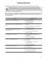
1
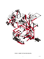
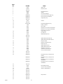
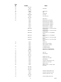
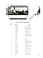
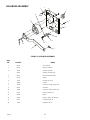
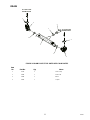
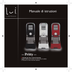
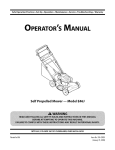
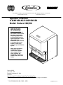
IMI CORNELIUS REMCOR INC g 500 REGENCY DRIVE g GLENDALE HEIGHTS, IL 60139--2268
Telephone (800) 551--4423
Facsimile (800) 519--4423
Operator’s Manual
ICE/BEVERAGE DISPENSER
Model: Enduro 200/250
IMPORTANT:
TO THE INSTALLER.
It is the responsibility of
the Installer to ensure that
the water supply to the
dispensing equipment is
provided with protection
against backflow by an air
gap as defined in
ANSI/ASME A112.1.2-1979;
or an approved vacuum
breaker or other such
method as proved effective
by test.
Water pipe connections
and fixtures directly
connected to a potable
water supply shall be
sized, installed, and
maintained according to
Federal, State, and Local
Codes.
Part No.92108
January31, 1995
Revised: September 26, 2000
Revision F
THIS DOCUMENT CONTAINS IMPORTANT INFORMATION
This Manual must be read and understood before installing or operating this equipment
Ó IMI CORNELIUS INC; 1995 - 2000
PRINTED IN U.S.A
TABLE OF CONTENTS
Page
MAINTENANCE . . . . . . . . . . . . . . . . . . . . . . . . . . . . . . . . . . . . . . . . . . . . . . . . . . . . . . . . . . .
1
DAILY (OR AS REQUIRED) . . . . . . . . . . . . . . . . . . . . . . . . . . . . . . . . . . . . . . . . . . . . 1
WEEKLY (OR AS REQUIRED) . . . . . . . . . . . . . . . . . . . . . . . . . . . . . . . . . . . . . . . . . 1
MONTHLY . . . . . . . . . . . . . . . . . . . . . . . . . . . . . . . . . . . . . . . . . . . . . . . . . . . . . . . . . . .
START-UP & OPERATING INSTRUCTIONS . . . . . . . . . . . . . . . . . . . . . . . . . . . . . .
CLEANING INSTRUCTIONS . . . . . . . . . . . . . . . . . . . . . . . . . . . . . . . . . . . . . . . . . . . .
DISPENSER . . . . . . . . . . . . . . . . . . . . . . . . . . . . . . . . . . . . . . . . . . . . . . . . . . . . . . . . . .
BEVERAGE SYSTEM (IF APPLICABLE) . . . . . . . . . . . . . . . . . . . . . . . . . . . . . . . . . . . . .
1
1
1
2
3
CLEANING . . . . . . . . . . . . . . . . . . . . . . . . . . . . . . . . . . . . . . . . . . . . . . . . . . . . . . . . . . . .
3
CLEANING DISPENSING VALVES . . . . . . . . . . . . . . . . . . . . . . . . . . . . . . . . . . . . . 3
SANITIZING . . . . . . . . . . . . . . . . . . . . . . . . . . . . . . . . . . . . . . . . . . . . . . . . . . . . . . . . . 3
TROUBLESHOOTING . . . . . . . . . . . . . . . . . . . . . . . . . . . . . . . . . . . . . . . . . . . . . . . . . . . . . .
5
BLOWN FUSE OR CIRCUIT BREAKER. . . . . . . . . . . . . . . . . . . . . . . . . . . . . . . . . . .
GATE DOES NOT OPEN. AGITATOR DOES NOT TURN. . . . . . . . . . . . . . . . . . .
GATE DOES NOT OPEN OR IS SLUGGISH. AGITATOR TURNS. . . . . . . . . . .
ICE DISPENSES CONTINUOUSLY. . . . . . . . . . . . . . . . . . . . . . . . . . . . . . . . . . . . . . .
SLUSHY ICE. WATER IN HOPPER. . . . . . . . . . . . . . . . . . . . . . . . . . . . . . . . . . . . . .
5
5
5
5
5
BEVERAGES DO NOT DISPENSE. . . . . . . . . . . . . . . . . . . . . . . . . . . . . . . . . . . . . . .
BEVERAGES TOO SWEET. . . . . . . . . . . . . . . . . . . . . . . . . . . . . . . . . . . . . . . . . . . . .
BEVERAGE NOT SWEET ENOUGH. . . . . . . . . . . . . . . . . . . . . . . . . . . . . . . . . . . . .
BEVERAGES NOT COLD (UNITS WITH BUILT--IN COLD PLATE). . . . . . . . . . .
SOLENOID ASSEMBLY . . . . . . . . . . . . . . . . . . . . . . . . . . . . . . . . . . . . . . . . . . . . . . . .
DRAIN . . . . . . . . . . . . . . . . . . . . . . . . . . . . . . . . . . . . . . . . . . . . . . . . . . . . . . . . . . . . . . . .
WARRANTY . . . . . . . . . . . . . . . . . . . . . . . . . . . . . . . . . . . . . . . . . . . . . . . . . . . . . . . . . . . . . .
5
5
6
6
12
13
14
LIST OF FIGURES
FIGURE 1. CABINET SECTION EXPLODED VIEW . . . . . . . . . . . . . . . . . . . . . . . .
FIGURE 2. ELECTRICAL BOX ASSEMBLY . . . . . . . . . . . . . . . . . . . . . . . . . . . . . . .
FIGURE 3. SOLENOID ASSEMBLY . . . . . . . . . . . . . . . . . . . . . . . . . . . . . . . . . . . . . .
FIGURE 4. DRAIN FOR Z STYLE UNITS WITH COLD PLATES . . . . . . . . . . . . .
i
7
11
12
13
92108
MAINTENANCE
The following dispenser maintenance should be performed at the intervals indicated:
DAILY (or as required)
Remove foreign material from vending area drip tray to prevent drain blockage.
WEEKLY (or as required)
Clean vending area. Check for proper water drainage from the vending area drip tray.
MONTHLY
Clean and sanitize the hopper interior and beverage system if applicable (see CLEANING INSTRUCTIONS).
START-UP & OPERATING INSTRUCTIONS
Fill the hopper with ice. Dispense several large cups of ice (approximately 20 to 30 seconds total dispensing time)
to allow ice to fill the cold plate cabinet. Add ice to the hopper as necessary to refill and replace the lid. Allow 10 to
15 minutes for the cold plate to cool down. Repeat this procedure whenever the dispenser has run out of ice. Start
up the beverage system and adjust faucets to the proper brix. Contact your local syrup distributor for complete
information on the beverage system.
In normal operation, pushing the ice dispenser mechanism will cause ice to flow from the ice chute. Ice flow will
continue until the dispenser mechanism is released. Dispensing of any faucet will provide beverage of the
appropriate flavor.
CAUTION: Use caution to avoid spilling ice when filling dispenser. Clean up immediately any
spilled ice from filling or operating the unit. To prevent contamination of ice, the lid must be
installed on the unit at all times.
If the dispenser fails to dispense ice or beverage see troubleshooting guide.
CLEANING INSTRUCTIONS
WARNING: Disconnect Power Before Cleaning! Do not use metal scrapers, sharp objects or
abrasives on the ice storage hopper, top cover and the agitator disk, as damage may result.
Do not use solvents or other cleaning agents, as they may attack the plastic material.
Soap solution - use a mixture of mild detergent and warm 100 degrees F potable water.
Sanitizing solution - use 1/2 ounce of household bleach in 1 gallon of potable water. Preparing the sanitizing
solution to this ratio will create a solution of 200 PPM.
1
92108
DISPENSER
1. CLEANING EXTERIOR SURFACES
Important: Perform the following daily.
A.
Remove the cup rest from drip tray.
B.
Wash the drip tray with soap solution. Rinse with clean water and allow solution to run down the drain.
C.
Wash cup rest with soap solution and rinse in clean water. Install the cup rest into the drip tray.
D.
Clean all exterior surfaces with soap solution and rinse in clean water.
2. COLD PLATE INSPECTION BEFORE CLEANING
A.
Remove splash panel.
B.
Remove the plastic cold plate cover to expose the cold plate.
C.
Locate and remove any debris from the cold plate, drain trough and make certain that the drain holes
are not clogged.
D.
Reinstall the cold plate cover.
E.
Reinstall the splash panel in the reverse order in which it was removed.
3. CLEANING INTERIOR SURFACES
CAUTION: When pouring liquid into the hopper, do not exceed the rate of 1/2 gallon per
minute.
Important: Perform the following at least once a month.
A.
Remove agitator assembly.
B.
Using a long handle nylon bristle brush, clean the interior of the hopper, top, cover and cold plate with
soap solution. The cold plate can be reached by going through the ice opening on the hopper bottom.
Make certain to reach the entire surface of the cold plate including the corners. Clean the agitator
assembly with soap solution using a nylon brush or a sponge. Thoroughly rinse the hopper, top cover,
agitator and cold plate surfaces with clean potable water.
C.
Remove merchandiser and ice chute cover from dispenser.
D.
With a nylon bristle brush or sponge, clean the inside of the ice chute, gasket and cover with soap
solution and rinse thoroughly to remove all traces of detergent.
E.
Re-assemble agitator assembly. Take special care to ensure that the thumbscrew is tight.
F.
Using a mechanical spray bottle filled with sanitizing solution, spray the entire interior and agitator
assembly. Allow to air dry.
G.
Re-assemble ice chute assembly.
H.
Using a mechanical spray bottle filled with sanitizing solution, spray the inside of the ice chute. Allow to
air dry.
I.
Reinstall merchandiser.
92108
2
BEVERAGE SYSTEM
(IF APPLICABLE)
CLEANING
WARNING: Disconnect Power Before Cleaning! Do not use metal scrapers, sharp objects or
abrasives on the ice storage hopper, top cover and the agitator disk, as damage may result.
Do not use solvents or other cleaning agents, as they may attack the plastic material.
Soap solution - Use a mixture of mild detergent and warm 100 degrees F potable water.
Sanitizing solution - Use 1/2 ounce of household bleach in 1 gallon of potable water. Preparing the sanitizing
solution to this ratio will provide the required solution of 200 PPM.
Cleaning tank - Fill clean, empty tank with a mixture of mild detergent and five (5) gallons of warm 120 degrees F
potable water.
CLEANING DISPENSING VALVES
Refer to addendum supplied with the unit that is applicable to the manufacturer of the valves installed on the unit.
SANITIZING
IMPORTANT: Only trained and qualified persons should perform these cleaning and sanitizing
procedures.
Sanitize tank systems, Post-Mix and Pre-Mix
1. Remove all the quick disconnects from all the tanks. Fill a suitable pail or bucket with soap solution.
2. Submerge all disconnects (gas and liquid) in the soap solution and then clean them using a nylon bristle
brush. (Do not use a wire brush). Rinse with clean water.
3. Prepare sanitizing solution and using a mechanical spray bottle, spray the disconnects. Allow to air dry.
4. Using a clean, empty tank, prepare five (5) gallons of the sanitizing solution. Rinse the tank disconnects with
approximately 9 oz. of the sanitizing solution. Close the tank.
5. Prepare cleaning tank by filling clean five (5) gallon tank with a mixture of mild detergent and 120 degrees F
potable water.
6. Connect a gas disconnect to the tank and then apply one of the product tubes to the cleaning tank. Operate
the appropriate valve until liquid dispensed is free of any syrup.
7. Disconnect cleaning tank and hook up sanitizing tank to syrup line and CO2 system.
8. Energize beverage faucet until chlorine sanitizing solution is dispensed through the faucet. Flush at least two
(2) cups of liquid to insure that the sanitizing solution has filled the entire length of the syrup tubing.
9. Allow sanitizer to remain in lines for fifteen (15) minutes.
10. Repeat the step above, applying a different product tube each time until all tubes are filled with the sanitizing
solution.
3
92108
11. For post-mix valves, remove the nozzle and syrup diffuser and clean them in a mild soap solution. Rinse
with clean water, then reinstall the nozzle and syrup diffuser on the valve.
12. For pre-mix valves, disconnect all product tubes from the tank of sanitizing solution and then open the valves
to allow the pressure to be relieved. Remove the valves from the dispenser, disassemble and wash
thoroughly in a mild soap solution.
13. Rinse the parts in clean water, reassemble the valve and reconnect it to the dispenser.
14. Discard the tank of sanitizing solution and reconnect the product (syrup or pre-mix) tanks. Operate the
valves until all sanitizer has been flushed from the system and only product (syrup or pre-mix) is flowing.
Sanitize syrup lines, B-I-B Systems
1. Remove all the quick disconnects from all the B-I-B containers.
2. Fill a suitable pail or bucket with soap solution.
3. Submerge all disconnects (gas and liquid) in the soap solution and then clean them using a nylon bristle
brush. (Do not use a wire brush). Rinse with clean water.
4. Using a plastic pail, prepare approximately five (5) gallons of sanitizing solution.
5. Rinse the B-I-B disconnects in the sanitizing solution.
6. Sanitizing fittings must be attached to each B-I-B disconnect. If these fittings are not available, the fittings
from empty B-I-B bags can be cut from the bags and used. These fittings open the disconnect so the
sanitizing solution can be drawn through the disconnect.
7. Place all the B-I-B disconnects into the pail of sanitizing solution. Operate all the valves until the sanitizing
solution is flowing from the valve. Allow sanitizer to remain in lines for fifteen (15) minutes.
8. Remove the nozzle and syrup diffuser from each valve and clean them in a soap solution. Rinse with clean
water and reassemble the nozzle and syrup diffuser to the valve.
9. Remove the sanitizing fittings from the B-I-B disconnects and connect the disconnects to the appropriate
B-I-B container. Operate the valves until all sanitizer has been flushed from the system and syrup is flowing
freely.
92108
4
TROUBLESHOOTING
IMPORTANT: Only qualified personnel should service internal components or electrical wiring.
WARNING: If repairs are to be made to a product system, remove quick disconnects from
the applicable product tank, then relieve the system pressure before proceeding. If repairs
are to be made to the CO2 system, stop dispensing, shut off the CO2 supply, then relieve the
system pressure before proceeding. If repairs are to be made to the refrigeration system, make sure
electrical power is disconnected from the unit.
Should your unit fail to operate properly, check that there is power to the unit and that the hopper contains ice. If the unit does not dispense, check the following chart under the appropriate symptoms to aid
in locating the defect.
Probable Cause
Trouble
BLOWN FUSE OR CIRCUIT BREAKER.
GATE DOES NOT OPEN. AGITATOR DOES NOT
TURN.
GATE DOES NOT OPEN OR IS SLUGGISH.
AGITATOR TURNS.
ICE DISPENSES CONTINUOUSLY.
SLUSHY ICE. WATER IN HOPPER.
BEVERAGES DO NOT DISPENSE.
BEVERAGES TOO SWEET.
5
A.
Short circuit in wiring.
B.
Defective gate solenoid.
C.
Defective agitator motor.
A.
No power.
B.
Bent depressor plate (does not actuate switch).
C.
Defective dispensing switch.
A.
Defective gate solenoid.
B.
Excessive pressure against gate slide.
C.
Defective Rectifier.
A.
Stuck or bent depressor plate (does not
release switch).
B.
Defective dispensing switch.
C.
Improper switch installation.
A.
Blocked drain.
B.
Unit not level.
C.
Poor ice quality due to water quality or
icemaker problems.
D.
Improper use of flaked ice.
A.
No 24 volt power to faucets.
B.
No CO2 pressure.
A.
Carbonator not working.
B.
No CO2 pressure in carbonator.
C.
Faucet brix requires adjusting.
92108
Trouble
Probable Cause
BEVERAGE NOT SWEET ENOUGH.
BEVERAGES NOT COLD (UNITS WITH BUILT--IN
COLD PLATE).
A.
Empty syrup tank.
B.
Faucet brix requires adjusting.
A.
Unit standing with no ice in hopper -- no ice in
cold plate cabinet.
NOTE: Contact your local syrup or beverage equipment distributor for additional information and
troubleshooting of beverage system.
92108
6
Part # Corrections/Update Document
Unit Type/Model #
Manual #
ED200/250
92108
ICE/BEVERAGE
DISPENSER
Revision 2 8/11/06
Page Item Old
Part
8
8
Desc.
New Part
Desc.
15093
Sink Extension
Jls
Jls
8
22
30895
Dispense Switch
02070
Dispense Switch
Kit
8
25
33387
Agitator Motor
120V
629088531
Kit, Agitator Motor
Replacement
629088782
Agitator Motor
Service
White Lens ED200
9
54
52949
9
57
53290
9
57
53292
10
89
10
95
10
100
Graphics
92183
10
100
Graphics
92184
10
100
Graphics
92046
10
100
Graphics
92047
10
100
Graphics
92079
10
100
Graphics
92080
10
100
Graphics
92081
71011
4” Caster Leg
70970
71094
Hopper Foamed
Assy Non Cold
Plate Unit
Hopper Foamed
Assy Non Cold
Plate Unit
4” Black Plastic
Leg
Cup-Rest Optifill
(slanted)
Coca-Cola
Graphics ED200
Coca-Cola
Graphics ED250
Pepsi Graphics
ED200
Pepsi Graphics
ED250
Generic Graphics
ED200
Generic Graphics
ED250
Dr. Pepper
Graphics ED200
Agent Date
SRV
Notes
1/16/03 Use this number for
units manufactured on
and before 11/15/98.
After this date use
620028702. Serial
number cut off: DF
units ZRM1013131, ED
units 62A9841ED343
1/16/03 Includes actuator
switch, boot, & spacer
(items 14,22,& 91)
2/1/06 For units prior to serial#
62A0540ED248
SRV
For units beginning with
serial #62A0540ED248
1/16/03 24.81x11.11
Use 52950 for ED250
24.81x15.11
1/6/06 For ED200
SRV
1/6/06
Jls
For ED250
Jls
1/16/03 Sold individually
Jls
1/16/03 29.1x7.5
Jls
Jls
1/16/03 Must order thru Coke
USA Parts
1/16/03 Must order thru Coke
USA Parts
1/16/03 11.083x24.794
Jls
1/16/03 15.083x24.794
Jls
1/16/03 11.083x24.794
3 Cups Refreshing
1/16/03 15.083x24.794
3 Cups Refreshing
1/16/03 11.083x24.794
Jls
Jls
Jls
10
100
Graphics
92082
10
100
Graphics
92085
10
100
Graphics
92086
10
100
Graphics
92083
10
100
Graphics
92084
11
10
31763
629087448
11
10
32828
Agitator Timer
120V
Agitator Timer
220-240V
12
629087451
70485
n/a
n/a
91978
n/a
n/a
91974
n/a
n/a
n/a
n/a
08052
33666
n/a
n/a
n/a
n/a
31001
629080104
n/a
n/a
n/a
Dr Pepper
Graphics ED250
7-Up Graphics
ED200
7-Up Graphics
ED250
RC Cola Graphics
ED200
RC Cola Graphics
ED250
Agitator Timer Kit
120V
Agitator Timer Kit
220-240V
Gate Slide Spring
Jls
1/16/03 15.083x24.794
Jls
1/16/03 11.083x24.794
Jls
1/16/03 15.083x24.794
Jls
1/16/03 11.083x24.794
Jls
1/17/03 15.083x24.794
Jls
1/16/03
Jls
1/16/03
Jls
1/16/03 Attaches to gate lift
arm on Solenoid Assy.
Need qty 2
1/16/03 Must order thru Coke
USA Parts
1/16/03 20.97x14.75 Cup
Splash
1/16/03 Two clear side guards
1/16/03 Red light
Coca Cola Side
Decal ED200/250
Pepsi Side Decal
ED200/250
Splashguard Kit
Low Ice Indicator
Light
Thermostat
Kit Sink to Z Style
ED2XX
Jls
629080304
Kit Z Style to Sink
ED2XX GRAY
Jls
n/a
629080303
Kit Z Style to Sink
ED2XX BLACK
Jls
n/a
n/a
32977
Jls
n/a
n/a
70739
Keylock Switch
w/Keys
Key
1/16/03 For low light indicator
1/16/03 Z = No drip tray or cuprest. Kit removes drip
tray/cup-rest. Allows
unit to sit on counter
with built in tray and
cup-rest.
1/16/03 Z = No drip tray or cuprest. Kit adds drip tray
and cup-rest to unit.
1/16/03 Z = No drip tray or cuprest. Kit adds drip tray
and cup-rest to unit.
1/17/03
Jls
1/17/03 Key is marked D001
Jls
Jls
Jls
Jls
Jls
90
57
5
33
80
87
67 64
67 1 93
56
27
68 26
39
63
77
79
92
94
4
C
SEE DETAIL
74 85
32
88
52
50
77
77
67
74
24
76
6
66
46 76
62
44
49
72
30
65
25
48
10
88
73
34
72
82
34 18
22
91
74
54
60
100
14
53
55
95 17
16
16
18
12
84
15
88
72
23
88
86
59 72
8
13
101
DETAIL C
SCALE0.093
83
FIGURE 1. CABINET SECTION EXPLODED VIEW
7
92108
92108
Item
No.
Part No.
1
21491
2
22081R
3
Not Used
Name
Slide, Gate
Restrictor, Gate
4
29541R
5
29694
Plate, Motor Mount
6
29555
7
629080208
629080204
Panel, Lower Front (Z Model)
8
620028702
Support, Drip Tray
9
Not Used
Agitator
Cover, Rear Wrapper
Panel, Lower Front (For Drip Tray)
10
29547
11
Not Used
Cabinet
12
Contact Sales
13
53011
Fitting, Cold Plate
14
31007
Boot, Switch
15
15500
Dispense Lever, Short (Cup Activated)
15488
Dispense Lever, Long (Cup Activated)
Panel/Cold Plate/Valve Ass’y
15502
Push Lever Ice Dispense
16
50767
Snap Bushing
17
10145
Pin, Drip Tray
Baffle, Beverage Panel
18
15090
19
Not Used
20
Not Used
21
30794
Agitator Motor Heater 120 Volt
32826
Agitator Motor Heater 220-240 Volt
22
30895
Dispense Switch
23
27107
Retainer, Ice Dispense lever
24
31928
Bulb, Florescent
25
33387
Agitator Motor 120 Volt
33404
Agitator Motor 220-240 Volt
26
32954
Solenoid Ass’y 120 Volt
33409
Solenoid Ass’y 220-240 Volt
27
53268
Cover, Foamed Cold Plate
28
Not Used
29
Not Used
30
620302501
Electrical Box Ass’y, 120V (ED 200
Models)
620302502
Electrical Box Ass’y, 120V (ED 250
Models)
620310201
Electrical Box Ass’y, 220-240V (ED
200 Models)
620310202
Electrical Box Ass’y, 220-240V (ED
250 Models)
31
Not Used
32
29542
33
53255
Cover, Access (Cold Plate)
34
71010
Washer, Captivating No. 8
35
Not Used
36
Not Used
37
Not Used
38
Not Used
39
620019701
40
Not Used
41
Not Used
42
Not Used
Bracket, Motor Mount
Hinge Gusset
8
Item
No.
43
Part No.
Name
Not Used
44
53199
45
Not Used
Seal, Motor
46
51891
47
***51908
48
71025
49
620500901
50
53168
51
Not Used
52
15132
Motor Mount
53
53001
Merchandiser, Gray (ED250)
53000
Merchandiser, Gray, (ED200)
52912
Merchandiser, Black, (ED250)
52911
Merchandiser, Black, (ED200)
15754
Merchandiser, S.S., (ED250)
15755
54
55
56
57
Gasket, Gate
Plug
Strap, Motor
Ice Chute
Ice Chute Cover
Merchandiser, S.S., (ED200)
620011505
Merchandiser, S.S., (For Lid and Straw
Holder ED250)
620011509
Merchandiser, S.S., (For Lid and Straw
Holder ED200)
620011506
Merchandiser, S.S., (For Medallion
ED250)
620011510
Merchandiser, S.S., (For Medallion
ED200)
620011507
Merchandiser, S.S., (For Low Ice Light
ED250)
620011511
Merchandiser, S.S., (For Low Ice Light
ED200)
52950
Panel, Inner
53211
Drip Tray, Gray, Insulated
53210
Drip Tray, Black, Insulated
53018
Lid, Dispenser, Gray
52909
Lid, Dispenser, Black
52960
Hopper Ass’y, Insulated (ED250)
52916
Hopper Ass’y, Insulated (ED200)
58
Not Used
59
52967
Plug, Foot
60
52972
Tab, Retaining
61
Not Used
62
70016
Hex Nut, No. 10-32
63
70017
Hex Nut, No. 10-32, Nyloc
64
53299
Tab, Retaining
65
70242
Screw, No. 10-32 By 3/8-In. Long
66
70015
Hex Nut, No. 10-32, Keps
67
70056
Washer, No. 10
68
70067
Washer, 7/32 I.D. x 7/8 O.D. x 3/64
Thk Plated
69
Not Used
70
Not Used
71
Not Used
72
70171
Screw, No. 8-32 By 3/8-In. Long
73
70178
Screw, No. 8-32 By 1/2-In. Long
74
70204
Screw, No. 8 By 1/2-In. Long
75
Not Used
76
71033
9
Screw, 3/8-16 By 3/4-In. Long
92108
Item
No.
Part No.
Name
77
70068
Washer, 3/8 I.D. x 11/16 O.D. x .070
Thk
78
Not Used
79
71061
Washer, 7/16 I.D. x 1 1/8 O.D. x .063
Thk
80
70320
Pop Rivet, 1/8 Dia.
81
70341
Spring, Motor Heater
82
71006
83
70478R
Screw, No. 8-32 By 1 1/8-In. Long
Clip, Push-on
84
70555
85
620022801
Brace, Reflector
Screw, No. 8-32 By 2 5/8-In. Long
86
620701601
Sheet Metal Screw, No. 10 By 1/2-In.
Long
87
70456
88
70959
Hex Nutsert, No. 8-32
*89
71011
Leg
90
15087
Retainer, Agitator
91
70847
Spacer, Switch
92
71059
Wing Nut, 3/8-16
Pop Rivet, 3/16 Dia.
93
71089
Shoulder Screw, No. 8-32
94
71028
Shoulder Screw, 1/4-20
95
71039
Cup Rest
*96
51288
Adapter, 1-In. Barb By 3/4 MPT (For
Drip Tray Drain)
*97
50952
Adapter, 3/4 Soc By 3/4 FPT (For Drip
Tray Drain)
*98
70750
Hose Clamp (For Drip Tray Drain)
*99
620702201
*100
Contact Sales
101
620045417
NOTES:
Brush, Cold Plate Cleaning
Graphics
Support Beverage Panel
*NOT SHOWN
***FOR 220-240V MODELS, 51908 PLUG REPLACED BY
620303001 PUSH-BUTTON SWITCH ACTUATOR AND
620303002 SWITCH BLOCK
92108
10
17
15
14
6
18
16
1
12
5
4
2
3
9
13
8
11
10
FIGURE 2. ELECTRICAL BOX ASSEMBLY
Item
No.
1
2
Part No.
Name
620022001
Electrical Box (ED250)
620020902
Electrical Box (ED200)
620022101
Reflector Panel (ED250)
620020901
Reflector Panel (ED200)
3
620021101
Clamp, Capacitor
4
33160R
Capacitor, Agitator Motor
5
30995
Power Cord, 120 Volts
620302901
Power Cord, 220-240 Volts
30960
Terminal Board, 120 Volts
31107
Terminal Board, 220-240 Volts
6
7
Not Used
8
31620
Starter
9
31621
Ballast, 120 Volts
33662
Ballast, 220-240 Volts
31763
Agitation Timer, 120 Volts
32828
Agitation Timer, 220-240 Volts
11
620302201
Socket, Starter
12
32682
Transformer, 120 Volts
32829R
Transformer, 220-240 Volts
13
620302101
Lampholder
14
33162
Relay, Start, 120 Volts
620306601
Relay, Start, 220-240 Volts
15
32958
Rectifier
16
620304601
Varistor, 220-240 Volts
17
620307301
Filter, 220-240 Volts
18
32244
Terminal Strip, 220-240 Volts
10
11
92108
SOLENOID ASSEMBLY
4
9
11
5
14
3
6
5
12
10
15
13
8
7
1
2
FIGURE 3. SOLENOID ASSEMBLY
Item
No.
Part No.
1
28173
Arm, Gate Lift
2
50754
Bearing, Gate Arm
3
32957
Solenoid, 120 Volts
33397
Solenoid, 220-240 Volts
4
28172
Plate, Solenoid Mounting
5
50752
Isolator
6
70015
Hex Nut, No. 10-32
7
51689
Locktite
8
70162
Screw, No. 8-32 By 1/4-In. Long
9
50705
Tie Cable
10
70165
Screw, No. 8-32 By 5/8-In. Long
11
71007
Spring, Solenoid Arm
12
51348
Spacer
13
70067
Washer, .218 I.D. By .875 O.D.
14
70057
Lockwasher, No. 10
15
70052
Flatwasher, No. 8
92108
Name
12
DRAIN
TO COLD PLATE
DRAIN ELBOW
1
3
4
1
TO COLD PLATE
DRAIN ELBOW
1
1
2
1
3
FIGURE 4. DRAIN FOR Z STYLE UNITS WITH COLD PLATES
Item
No.
Part No.
Qty
1
70750
5
Hose Clamp
2
53169
1
Drain Tube
3
51280
2
Elbow
4
53293
1
Coupler
Name
13
92108
WARRANTY
IMI Cornelius Inc. warrants that all equipment and parts are free from defects in material and workmanship
under normal use and service. For a copy of the warranty applicable to your Cornelius, Remcor or Wilshire
product, in your country, please write, fax or telephone the IMI Cornelius office nearest you. Please provide the
equipment model number, serial number and the date of purchase.
IMI Cornelius Offices
AUSTRALIA D P.O. 210, D RIVERWOOD, D NSW 2210, AUSTRALIA D (61) 2 533 3122 D FAX (61) 2 534 2166
AUSTRIA D AM LANGEN FELDE 32 D A-1222 D VIENNA, AUSTRIA D (43) 1 233 520 D FAX (43) 1-2335-2930
BELGIUM D BOSKAPELLEI 122 D B-2930 BRAASCHAAT, BELGIUM D (32) 3 664 0552 D FAX (32) 3 665 2307
BRAZIL D RUA ITAOCARA 97 D TOMAS COELHO D RIO DE JANEIRO, BRAZIL D (55) 21 591 7150 D FAX (55) 21 593 1829
ENGLAND D TYTHING ROAD ALCESTER D WARWICKSHIRE, B49 6 EU, ENGLAND D (44) 789 763 101 D FAX (44) 789 763 644
FRANCE D 71 ROUTE DE ST. DENIS D F-95170 DEUIL LA BARRE D PARIS, FRANCE D (33) 1 34 28 6200 D FAX (33) 1 34 28 6201
GERMANY D CARL LEVERKUS STRASSE 15 D D-4018 LANGENFELD, GERMANY D (49) 2173 7930 D FAX (49) 2173 77 438
GREECE D 488 MESSOGION AVENUE D AGIA PARASKEVI D 153 42 D ATHENS, GREECE D (30) 1 600 1073 D FAX (30) 1 601 2491
HONG KONG D 1104 TAIKOTSUI CENTRE D 11-15 KOK CHEUNG ST D TAIKOKTSUE, HONG KONG D (852) 789 9882 D FAX (852) 391 6222
ITALY D VIA PELLIZZARI 11 D 1-20059 D VIMARCATE, ITALY D (39) 39 608 0817 D FAX (39) 39 608 0814
NEW ZEALAND D 20 LANSFORD CRES. D P.O. BOX 19-044 AVONDALE D AUCKLAND 7, NEW ZEALAND D (64) 9 8200 357 D FAX (64) 9 8200 361
SINGAPORE D 16 TUAS STREET D SINGAPORE 2263 D (65) 862 5542 D FAX (65) 862 5604
SPAIN D POLIGONO INDUSTRAIL D RIERA DEL FONOLLAR D E-08830 SANT BOI DE LLOBREGAT D BARCELONA, SPAIN D (34) 3 640 2839 D FAX (34) 3 654 3379
USA D ONE CORNELIUS PLACE D ANOKA, MINNESOTA D (612) 421-6120 D FAX (612) 422-3255
LD004
4/21/98
92108
14
THIS PAGE LEFT BLANK INTENTIONALLY
15
92108
IMI CORNELIUS INC.
Corporate Headquarters:
One Cornelius Place
Anoka, Minnesota 55303-6234
(612) 421-6120
(800) 238-3600