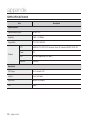
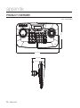
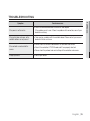
1
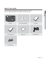
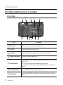
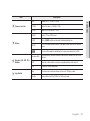
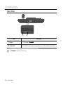
SYSTEM CONTROLLER User Manual SPC-2010 System Controller User Manual Copyright ©2012 Samsung Techwin Co., Ltd. All rights reserved. Trademark is the registered logo of Samsung Techwin Co., Ltd. The name of this product is the registered trademark of Samsung Techwin Co., Ltd. Other trademarks mentioned in this manual are the registered trademark of their respective company. Restriction Samsung Techwin Co., Ltd shall reserve the copyright of this document. Under no circumstances, this document shall be reproduced, distributed or changed, partially or wholly, without formal authorization of Samsung Techwin. Disclaimer Samsung Techwin makes the best to verify the integrity and correctness of the contents in this document, but no formal guarantee shall be provided. Use of this document and the subsequent results shall be entirely on the user’s own responsibility. Samsung Techwin reserves the right to change the contents of this document without prior notice. Design and specifications are subject to change without prior notice. The default password can be exposed to a hacking thread so it is recommended to change the password after installing the product. Note that the security and other related issues caused by the unchanged password shall be responsible for the user. overview IMPORTANT SAFETY INSTRUCTIONS ● 1. Read these instructions. OVERVIEW 2. Keep these instructions. 3. Heed all warnings. 4. Follow all instructions. 5. Do not use this apparatus near water. 6. Clean only with dry cloth. 7. Do not block any ventilation openings, Install in accordance with the manufacturer’s instructions. 8. Do not install near any heat sources such as radiators, heat registers, stoves, or other apparatus (including amplifiers) that produce heat. 9. Do not defeat the safety pu rpose of the polarized or grounding-type plug. A polarized plug has two blades with one wider than the other. A grounding type plug has two blades and a third grounding prong. The wide blade or the third prong are provided for your safety, If the provided plug does not fit into your outlet, consult an electrician for replacement of the obsolete outlet. 10. Protect the power cord from being walked on or pinched particularly at plugs, convenience receptacles, and the point where they exit from the apparatus. 11. Only use attachments/ accessories specified by the manufacturer. 12. Use only with the cart, stand, tripod, bracket, or table specified by the manufacturer, or sold with the apparatus. When a cart is used, use caution when moving the cart/ apparatus combination to avoid injury from tip-over. 13. Unplug this apparatus during lighting storms or when unused for long periods of time. 14. Refer all servicing to qualified service personnel. Servicing is required when the apparatus has been damaged in any way, such as power-supply cord or plug is damaged, liquid has been spilled or objects have fallen into the apparatus, the apparatus has been exposed to rain or moisture, does not operate normally, or has been dropped. English _3 overview WARNING TO REDUCE THE RISK OF FIRE OR ELECTRIC SHOCK, DO NOT EXPOSE THIS PROCUCT TO RAIN OR MOISTURE. DO NOT INSERT ANY METALLIC OBJECT THROUGH THE VENTILATION GRILLS OR OTHER OPENNINGS ON THE EQUIPMENT. Apparatus shall not be exposed to dripping or splashing and that no objects filled with liquids, such as vases, shall be placed on the apparatus. CAUTION CAUTION RISK OF ELECTRIC SHOCK. DO NOT OPEN CAUTION : TO REDUCE THE RISK OF ELECTRIC SHOCK. DO NOT REMOVE COVER (OR BACK). NO USER SERVICEABLE PARTS INSIDE. REFER SERVICING TO QUALIFIED SERVICE PERSONNEL. EXPLANATION OF GRAPHICAL SYMBOLS The lightning flash with arrowhead symbol, within an equilateral triangle, is intended to alert the user to the presence of “dangerous voltage” within the product’s enclosure that may be of sufficient magnitude to constitute a risk of electric shock to persons. The exclamation point within an equilateral triangle is intended to alert the user to the presence of important operating and maintenance (servicing) instructions in the literature accompanying the product. 4_ overview Please read the following recommend safety precautions carefully. Reference : Providing useful information for the user. Notice : If the instructions are not followed correctly damage to the goods or person may occur. For safety please read this manual for the before using of goods and keep it in the safe place. English _5 OVERVIEW User’s Manual is a guidance book on how to use the product. Below is a key to the following signs that are used in this manual. ● Do not Place this apparatus on an uneven surface. Do not install on a surface where it is exposed to direct sunlight, near heating equipment or heavy cold area. Do not place this apparatus near. Do not attempt to service this apparatus yourself. Do not place a glass of water on the product. Do not install near any magnetic sources. Do not block any ventilation openings. Do not place heavy items on the product. overview CONTENTS 3 3 6 8 9 10 Important Safety Instructions Contents Key Features What’s Included System Controller at a Glance INSTALLATION 13 Precautions 14 To Connect a RS-485/422 Device 19 19 24 Getting Started Controlling the PTZ Camera Controlling DVR OVERVIEW 13 CONNECTING TO AN EXTERNAL DEVICE 14 USING THE MENU 19 6_ overview MENU SETTING 32 32 34 35 Specifications Troubleshooting Product Overview OVERVIEW APPENDIX PTZ setting DVR Setting Controller Setting Joystick Calibration ● 26 26 27 28 31 English _7 overview KEY FEATURES SPC-2010 system controller enables you to control external devices such as PTZ camera, DVR using RS-485/422 communications. It provides a user-friendly interface with joystick. • Long-distance remote control • With RS-485/422 communications, the control distance is a maximum of 1km. • Integrated system control • With a single system controller, you can control all cameras (receiver unit), DVRs. Compatibility List • Camera • DVR SRD-XXXX series (Not supported by SRD-480D.) 8_ overview WHAT’S INCLUDED ● Unpack the product package and place the product on the floor or a flat surface. Check if the following components are all included in the product package. OVERVIEW ESC PWR PWR Tx 1 2 3 4 5 6 7 8 9 CLR 0 ENT MON CAM MENU PRESET GROUP FUNC SETUP PTZ MODE AUDIO REC SEARCH FREEZE ALARM Rx PTZ/DVR A/F AUX IRIS FOCUS W ZOOM T Main Unit User Manual CD (Optional) User Manual Quick Guide (Optional) Warranty Card Power Adaptor 1EA TRx Tx3 Tx2 Tx1 Terminal Block 1EA English _9 overview SYSTEM CONTROLLER AT A GLANCE Front Side b c ESC PWR PWR Tx Item 1 2 3 4 5 6 7 8 9 CLR 0 ENT MON CAM MENU PRESET GROUP FUNC SETUP PTZ MODE AUDIO REC SEARCH FREEZE ALARM Rx PTZ/DVR A/F AUX IRIS FOCUS W ZOOM T Description DVR Play Bar Play/Pause, Fast Forward/Fast Backward, Stop, Record b ESC / PWR Cancels a command or turns power on/off. c LCD Display Display the operation status and the setup menu of the system controller. Controller Selection Bar Used to select a camera, monitor or DVR. Joystick Controller You can manipulate the Pan/Tilt operation up or down in connection with the PTZ camera or receiver unit. Turn the joystick clockwise or counter clockwise to control zooming. You can control the direction of the connected controller from the menu screen of the controller. Camera Operation Bar Runs Preset, Group, Auto Focus and Aux output functions. DVR Control Bar Executes the selected DVR’s Audio, Search, screen mode selection, Freeze and Alarm Control. 10_ overview Item Control Iris (-: CLOSE/+: OPEN) FOCUS Adjust the focus (-: NEAR/+: FAR) ZOOM Zoom In/Out (W: WIDE/T: TELE) MENU Enters PTZ and DVR menu. FUNC Press [FUNC] button and desired function button to run. SETUP Press a number button and press [SETUP] button to enter the settings menu. OVERVIEW Others IRIS ● Camera Lens Bar Description Used in DVR mode for controlling the camera connected to the DVR. Number (0-9) Used to specify numeric characters for camera, monitor, DVR or Preset settings. ENT Move to a desired item using the navigation buttons and select it. CLR Cancel the current operation. Jog Used to search for forward/reverse frame in DVR play mode. Shuttle Forward/Reverse/Play/FF/REW in DVR play mode. Number (0-9), ENT, CLR Buttons Jog Shuttle English _11 overview Rear Side Tx1 Tx2 Tx3 TRx PROGRAM DC IN 12V b Item Description Power DC 12V input port. ( b RS-485/422 For RS-485/422 communication, connected to camera, DVR and other control devices. M [PROGRAM] is not for user’s accessing. 12_ overview ) installation PRECAUTIONS INSTALLATION • The product is designed for indoor use only. • Keep it away from water or moisture. • Do not put excessive force on it. • Do not pull out the power cable forcibly. • Do not dismantle it at your own. • Use only the rated I/O range. • Install the system controller on a flat table. • The layout of the system controller and the wiring system are critical for a proper system operation. • You must turn off the product before installing it. • A severe impact or vibration may cause a system failure. • Keep it away from a strong magnetic field or electric interference, or wireless devices such as radio or TV set. • Keep the installation site clean and dust-free all the time while or after you have installed the system controller. • Leaving an abnormal smoke or smell as it is may lead to a fire or electric shock. If this is the case, turn off the system controller immediately and contact us for a technical assistance. • Take an appropriate action if you find: damp floor, unearthed power extension cord, peeled-off power cable, or absence of safety grounding. - Operation Temperature : 0°C ~ 40°C - Storage Temperature : -30°C ~ +60°C - Operation Humidity : 20% ~ 85% RH - Storage Humidity : ~ 90% RH - Power Consumption : DC 12V, Max 1.1W ( J ● Before you install the system controller, read through and comply with the following instructions. ) Use a dry cloth to wipe it out. If badly dirty or stained, use a cloth soaked into neutral detergent to wipe it out. Do not use volatile solvents such as alcohol, benzene or thinner that may damage the product surface. English _13 connecting to an external device SPC-2010 system controller can be used in connection with an external device such as camera or DVR. TO CONNECT A RS-485/422 DEVICE With the system controller, you can control the PTZ camera or DVR that supports RS-485/422 communication protocols. 1. Connect the rear Tx1 with RS-485 port of the PTZ camera or DVR. 2. According to the external device connected, select RS-485 (Half Duplex) or RS-422 (Full Duplex) connection. For RS-485/422 communications, pay special attention to the polarity (+/-). Use the provided terminal block in the product package. Check if the RS-485/422 device is compatible with SPC-2010. Tx3 Tx2 TRx M Tx1 Tx1 Tx2 Tx3 TRx PROGRAM DC IN 12V TRx Tx3 Tx2 Tx1 Connecting RS-485/422 Signal Wires • RS-485 Communications • RS-422 Communications Camera Controller Camera Controller RXD+ TRx+ RXD+ Tx1+ RXD– TRx– RXD– Tx1– TXD+ TRx+ TXD– TRx– You may use the Tx2 or Tx3 terminal instead of Tx1. 14_ connecting to an external device Connecting the PTZ Camera Depending on the camera, the polarity may differ. For more information, refer to the user manual of the PTZ camera. For the half duplex system - Connect Rx (+) of RS-485 port of the PTZ camera with TRx (+) of SPC-2010. - Connect Rx (–) of RS-485 port of the PTZ camera with TRx (–) of SPC-2010. If connecting a PTZ camera without using DVR device, you can connect to Tx1, Tx2 or Tx3 instead of TRx. /0 "6%*0@*/ "6%*0@065 "9*$0. *.0 7%$ 59 "9*$0. *.0 7%$ 59 $0. "9*$0. *.0 7%$ 39 (/% "VY TRx "VY /0 39 $POUSPMMFS 59 Tx3 (/% $0. 1PXFS "$_7 %%59%59%(/%"$0."/0 $POUSPMMFS 59 %%59%59%(/%"$0."/0 Tx2 Tx1 Tx2 Tx3 TRx 39 "MBSN0/ "MBSN0/ */*/(/%*/*/(/%$.//$$.//$ 7JEFP0VU 39 /$ / $0. /$ / $0. (/% */ */ (/% */ */ "MBSN English _15 CONNECTING TO AN EXTERNAL DEVICE M ● By connecting RS-485 port on the rear of the PTZ camera with Tx of SPC-2010, you can control the camera. TRx Tx3 Tx2 Tx1 Tx1 connecting to an external device For the full duplex system - Connect Rx (+) of RS-485 port of the PTZ camera with Tx1 (+) of SPC-2010. - Connect Rx (–) of RS-485 port of the PTZ camera with Tx1 (–) of SPC-2010. - Connect Tx (+) of RS-485 port of the PTZ camera with TRx (+) of SPC-2010. - Connect Tx (–) of RS-485 port of the PTZ camera with TRx (–) of SPC-2010. /0 "6%*0@*/ "6%*0@065 "9*$0. *.0 7%$ 59 "9*$0. *.0 7%$ 59 $0. "9*$0. *.0 7%$ 39 (/% "VY TRx "VY Tx3 Tx2 Tx1 TRx Tx3 Tx2 Tx1 16_ connecting to an external device /0 39 $POUSPMMFS 59 (/% $0. 1PXFS "$_7 %%59%59%(/%"$0."/0 $POUSPMMFS 59 %%59%59%(/%"$0."/0 Tx1 Tx2 Tx3 TRx 39 "MBSN0/ "MBSN0/ */*/(/%*/*/(/%$.//$$.//$ 7JEFP0VU 39 /$ / $0. /$ / $0. (/% */ */ (/% */ */ "MBSN Connecting SRD-16XX/8XX Series DVR ● Connect between DVR and SPC-2010 using RS-485 port on the rear of the DVR. - Connect Tx (+) of RS-485 port of the DVR with TRx (+) of SPC-2010. - Connect Tx (–) of RS-485 port of the DVR with TRx (–) of SPC-2010. CH 4 AUDIO OUT AC 100-240~ IN LOOP OUT CH 2 CH 3 VIDEO IN SPOT AUDIO IN CH 1 NETWORK ALARM OUT VGA ALARM IN SERIAL CONSOLE TRx Tx3 Tx2 Tx1 USB ALARM OUT Tx1 Tx2 Tx3 TRx TRx Tx3 Tx2 Tx1 For the full duplex system - Connect Tx (+) of RS-485 port of the DVR with TRx (+) of SPC-2010. - Connect Tx (–) of RS-485 port of the DVR with TRx (–) of SPC-2010. - Connect Rx (+) of RS-485 port of the DVR with Tx1 (+) of SPC-2010. - Connect Rx (–) of RS-485 port of the DVR with Tx1 (–) of SPC-2010. CH 4 AUDIO OUT AC 100-240~ IN LOOP OUT CH 2 CH 3 VIDEO IN SPOT AUDIO IN CH 1 NETWORK ALARM OUT VGA ALARM IN SERIAL CONSOLE TRx Tx3 Tx2 USB Tx1 Tx2 Tx3 TRx ALARM OUT TRx English _17 CONNECTING TO AN EXTERNAL DEVICE For the half duplex system Tx3 Tx2 Tx1 Tx1 connecting to an external device Connecting SRD-4XX DVR Connect RS-485 port on the rear of SRD-4XX with SPC-2010. For the half duplex system - Connect Tx (+) of SRD-4XX with TRx (+) of SPC-2010. - Connect Tx (–) of SRD-4XX with TRx (–) of SPC-2010. TRx Tx3 Tx2 Tx1 Tx1 Tx2 Tx3 TRx Tx3 Tx2 Tx1 TRx M Not supported by SRD-480D. 18_ connecting to an external device using the menu GETTING STARTED ● USING THE MENU Power 1. When powered off, press [PWR] to turn on. 2. When powered on, press and hold [PWR] to turn off. Initial Screen • SAMSUNG-T: Shows the current channel’s protocol used for the camera or DVR. • 9.6K: Shows the current channel’s baud rate set for the camera or DVR. SAMSUNG-T 9.6K ID : 001 • ID: Shows the current channel’s number. CONTROLLING THE PTZ CAMERA To enter PTZ control mode Press [PTZ/DVR] button to switch to PTZ control mode. To select a camera 1. Use the number buttons to enter the number of the camera of your choice. 2. Press the [CAM] or [ENT] button to set the camera ID to the selected number. You can set between 1 ~ 255. Note that the ID 0 allows SAMSUNG-T/E protocol only. English _19 using the menu PAN/TILT Control You can use the controller joystick to adjust the pan/tilt angle of the camera. The farther from the center of the joystick is, the faster the moving speed becomes. 20_ using the menu IRIS Press [IRIS – / +] on the controller to adjust the brightness of the camera video. ● USING THE MENU • IRIS – : camera Brighter • IRIS + : camera Darker FOCUS Press [FOCUS – / +] on the controller to fit the camera focus. • FOCUS – : Focus Closer • FOCUS + : Focus Farther ZOOM Turn the joystick clockwise, or press [T] to control the zoom-in operation of the camera. Turn the joystick counter clockwise, or press [W] to control the zoom-out operation of the camera. • ZOOM W : Zoom Wide • ZOOM T : Zoom Tele < Zoom Wide Action > < Zoom Tele Action > English _21 using the menu PRESET Move the camera to a pre-determined point. To set a preset 1. Using the joystick and controller buttons, move the camera to a desired location. 2. Enter a preset number. 3. Hold down the [PRESET] button for 2 seconds to save the preset location. To execute the preset 1. Select a camera. 2. Enter a desired number(s) using the number buttons and press [PRESET]. 3. The preset will be executed. M You can select preset numbers from 1 to 255 using the controller. The maximum preset location number varies depending on the camera model. (For more information, please refer to your camera’s user manual.) You can set up preset locations in the OSD menu of the camera. GROUP You can make a group of multiple presets before calling them in sequence. To set a group 1. Enter the group number. 2. Press the [GROUP] button to activate the Group mode. To pause the Group mode, move the joystick. M In order to use Group modes, you must set up the modes in the camera’s OSD menu prior to actual operation. Group function is available only for SAMSUNG-T/E protocol. SAMSUNG-E protocol allows SCAN function. 22_ using the menu A/F ● 1. Pressing the [A/F] button. USING THE MENU 2. Execute One Shot AF function of the camera. M A/F function is available in SAMSUNG-T/E and Pelco-D/P protocols. AUX Controls the camera’s Aux output operation. • AUX ON : Press the number of desired AUX channel and then briefly press [AUX] button to set Aux output to ON. • AUX OFF : Press the number of desired AUX channel and then press [AUX] button for about 2 seconds to set Aux output to OFF. M AUX function is available in SAMSUNG-T/E and Pelco-D/P protocols. English _23 using the menu CONTROLLING DVR Depending on the model, the DVR may have different features available. For details, refer to the applicable user manual. M An improper setting may cause a problem using the DVR. To enter DVR control mode Press [PTZ/DVR] button to switch to DVR control mode. To select a DVR 1. Use the number buttons to enter a DVR number (0~255) and press [ENT]. 2. Screen according to the selected DVR model appears. M PTZ control synchronizes to the settings configured in the selected DVR. When changed PTZ settings of the DVR, select the DVR as instructed above to refresh synchronization to changed settings. To select a DVR channel 1. Use the number buttons to enter the number for a desired DVR channel. 2. Press [CAM]. M Hold [FUNC] button and select a channel’s number button to switch to the desired DVR channel. (Channel 1 ~ 9) Controlling the DVR Spot Monitor If using DVR that supports Spot Out, press the buttons below in a row to control Spot Out. • To switch selected DVR’s Spot channel to a desired camera’s video: SPOT monitor number + [MON] + Channel number + [CAM] • To switch selected DVR’s Spot channel to a desired DVR’s split screen mode: SPOT monitor number + [MON] + [MODE] 24_ using the menu To control the DVR menu ● 1. To control the menus of the selected DVR, press [MENU] in the DVR control bar. To control the PTZ device that is connected to DVR Depending on used DVR model, you may not be able to directly control PTZ camera connected to the DVR. In such cases, press [PTZ/DVR] button in DVR control mode to switch to camera control mode, and then you can control the camera. To control the PTZ device in DVR mode 1. In DVR control mode, select a channel for PTZ control. 2. Press [ ] button to display “ ” on the right bottom side of the monitor. 3. Use joystick to control the PTZ camera connected to the DVR. 4. Press [ ] button again. “ the previous mode. ” on the right bottom side of the monitor disappears and restores DVR login When accessing DVR menu, logging in may prompt for password depending on the DVR’s settings configured. • You can enter the DVR password as in the way of channel selection. Ex) If the DVR’s password is “4321”, press buttons below in a row to login to the DVR. [4] + [CAM] + [3] + [CAM] + [2] + [CAM] + [1] + [CAM] M DVR password can be entered using the [FUNC] button too. Refer to “To select a DVR channel”. (Page 24) English _25 USING THE MENU 2. Use joystick and [ENT] to traverse DVR menu. menu setting PTZ SETTING From the PTZ setup screen, you can specify the protocol and baud rate. 1. Press [1] on the number pad. Hold down the [SETUP] button to enter the PTZ SETUP mode. 2. Enter the 4-digit password. Default Password : 4321 J The default password can be exposed to a hacking thread so it is recommended to change the password after installing the product. Note that the security and other related issues caused by the unchanged password shall be responsible for the user. 3. To change a channel address, select a channel by moving the joystick to the right or left. Or you can enter the channel number and then press the [ENT] button. 4. Change the <MODEL>, <BAUDRATE> and <PARITY> settings of the select channel. M To move between the options, move the joystick up or down. To change the value of the settings, move the joystick to the right or left. For the default settings values, please refer to the picture on the right. BAUDRATE : 9.6K, PARITY : NONE 5. Select the <SAVE> menu to save the changes. You can continue changing the settings by selecting different channels. To exit to the initial screen, select the <EXIT> menu or press the [ESC] button. J After changing the settings of a channel, you must select the <SAVE> menu. If you move to a different channel without using the <SAVE> menu, the changes will not be saved. Under Controller Serial Setup, Data Bit is fixed to 8 and Stop Bit to 1. Serial values of the controller and camera must match each other. Note that the ID 0 allows SAMSUNG-T/E protocol only. 26_ menu setting [ PTZ SETUP 1 ] PASSWORD [ **** ] [ PTZ SETUP 1] 1. ADDRESS : 001 [ PTZ SETUP 1] 2. MODEL : SAMSUNG-T [ PTZ SETUP 1] 3. BAUDRATE : 9.6K [ PTZ SETUP 1] 4. PARITY : NONE [ PTZ SETUP 1 ] 5. SAVE [ PTZ SETUP 1 ] 6. EXIT DVR SETTING 2. Enter the 4-digit password. Default Password : 4321 J The default password can be exposed to a hacking thread so it is recommended to change the password after installing the product. Note that the security and other related issues caused by the unchanged password shall be responsible for the user. 3. To change a channel address, select a channel by moving the joystick to the right or left. Or you can enter the channel number and then press the [ENT] button. 4. Change the <BAUDRATE> and <PARITY> settings of the select channel. M To move between the options, move the joystick up or down. To change the value of the settings, move the joystick to the right or left. For the default settings values, please refer to the picture on the right. Protocol : Samsung Techwin SAMSUNG-T BAUDRATE : 9.6K, PARITY : NONE 5. Select the <SAVE> menu to save the changes. You can continue changing the settings by selecting different channels. To exit to the initial screen, select the <EXIT> menu or press the [ESC] button. J After changing the settings of a channel, you must select the <SAVE> menu. If you move to a different channel without using the <SAVE> menu, the changes will not be saved. Under Controller Serial Setup, Data Bit is fixed to 8 and Stop Bit to 1. Serial values of the controller and camera must match each other. [ DVR SETUP 1 ] PASSWORD [ **** ] [ DVR SETUP 1] 1. ADDRESS : 001 [ DVR SETUP 1] 2. BAUDRATE : 9.6K [ DVR SETUP 1] 3. PARITY : NONE [ DVR SETUP 1 ] 4. SAVE [ DVR SETUP 1 ] 5. EXIT English _27 MENU SETTING 1. Press [2] on the number pad. Hold down the [SETUP] button to enter the DVR SETUP mode. ● From the DVR setup screen, you can specify the DVR type and baud rate. menu setting CONTROLLER SETTING 1. Press [3] on the number pad. 2. Hold down the [SETUP] button to enter the controller’s MAIN SETUP mode. [ MAIN SETUP ] PASSWORD [ **** ] 3. Enter the 4-digit password. Default Password : 4321 J The default password can be exposed to a hacking thread so it is recommended to change the password after installing the product. Note that the security and other related issues caused by the unchanged password shall be responsible for the user. 4. After changing the settings, select <YES> in the <SAVE/EXIT> menu to save the changes and move back to the initial screen. To cancel changes and move back to the initial screen, select <NO> in the <SAVE/EXIT> menu or press the [ESC] button. M [ MAIN SETUP ] 10. SAVE/EXIT To move between the options, move the joystick up or down. To change the value of the settings, move the joystick to the right or left. For the default settings values, please refer to the picture on the right. Firmware Version Displays the current version of the controller firmware. [ MAIN SETUP ] 1. v1.00_XXXXXX Serial Data Transfer Standard You can select serial communication mode from <RS485> and <RS422>. 28_ menu setting [ MAIN SETUP ] 2. COMM : RS485 LCD Backlight • ON : Keeps the backlight on at all times. [ MAIN SETUP ] 3. BACKLIGHT : AUTO • OFF : Keeps the backlight off at all times. Sleep If the controller is not used for specified time, it switches to SLEEP mode. Operating joystick or button of the controller exits SLEEP mode. [ MAIN SETUP ] 4. SLEEP : OFF Buzzer You can set the controller to beep on button pressings. • ON: Each pressing of a button beeps. • OFF: Pressing a button produces no sound. [ MAIN SETUP ] 5. BUZZER : ON Terminate To prevent the attenuation of communication signals between the camera and controller, the controller’s termination option must be <ON> if it is located farthest from the camera and controller communication loop. If the controller is in the middle of the camera and controller communication loop, turn the termination option <OFF>. [ MAIN SETUP ] 6. TERMINATE : ON English _29 MENU SETTING • AUTO : Turns the backlight off automatically if no command has been entered in the last 30 seconds. ● You can set the controller’s LCD backlight setting to OFF, ON or AUTO. menu setting Joystick’s Serial Command Transfer Cycle Select a PTZ serial command transfer cycle for using the joystick. Shortening the transfer cycle increases the response speed of the camera. J [ MAIN SETUP ] 7. JOY SPD : 100MS Shortening the joystick’s serial command transfer cycle may cause certain camera models to not process commands properly. To prevent and resolve such malfunctions, extend the transfer cycle. Password You can set the controller password. Enter a new password. [ MAIN SETUP ] 8. PASSWORD : **** M The default password is “4321”. J The default password can be exposed to a hacking thread so it is recommended to change the password after installing the product. Note that the security and other related issues caused by the unchanged password shall be responsible for the user. Factory Set Resets the controller’s current settings to the factory release default values and optimizes the joystick calibration. 30_ menu setting [ MAIN SETUP ] 9. FACTORY SET JOYSTICK CALIBRATION ● 1. Press [4] on the number pad. 3. At each option, move the joystick as far as you can, and then press the [ENT] button to calibrate. [ JOYSTICK CALI. ] 1. PTZ OFFSET ** [ JOYSTICK CALI. ] 2. PAN LEFT *** Move to the far left side Joystick in the Center [ JOYSTICK CALI. ] 4. TILT UP *** [ JOYSTICK CALI. ] 7. ZOOM TELE *** [ JOYSTICK CALI. ] 6. ZOOM WIDE *** Move to the far lower side Move to the far right side [ JOYSTICK CALI. ] 5. TILT DOWN *** Move to the far upper side Rotate to the Tele direction as far as possible [ JOYSTICK CALI. ] 3. PAN RIGHT *** Rotate to the Wide direction as far as possible [ J O Y S T I C K S AV E ] <NO> YES Select <YES> to save the changes and move back to the initial screen. Select <NO> or press the [ESC] button to cancel changes and move back to the initial screen. English _31 MENU SETTING 2. Hold down the [SETUP] button to enter the Joystick Calibration mode. appendix SPECIFICATIONS Item Description Communication Communication System RS-485 / 422 Baud Rate 2,400 ~ 57,600 bps Compatibility PTZ / DVR / RECEIVER PTZ SAMSUNG-T/E, PELCO-D/P, Panasonic, Vicon, AD, Honeywell, BOSCH, ELMO, GE Zoom SCZ DVR SRD (Not supported by SRD-480D.) Receiver Samsung-T Protocol Operational LCD Display 16 x 2 character LCD Joystick 3 axial Twist Zoom Jog Shuttle Control DVD playback OSD English 32_ appendix Environmental Operation Humidity 20%~85% RH APPENDIX 0°C ~ 40°C ● Operation Temperature Electrical Input Voltage /Current 12 VDC Power consumption 1.1W Mechanical Dimensions (WXHXD) W334.1 X H171.1 X D105.2 mm (13.15 X 6.74 X 4.14 inch) Weight 800g English _33 appendix PRODUCT OVERVIEW 171.1 (6.74") unit : mm (inches) 334.1 (13.15") 105.2 (4.14") 76.6 (3.02") 34_ appendix 28.6 (1.13") TROUBLESHOOTING ● Countermeasures If the power is not turned on • Check the connection between the main unit and adaptor. If the problem persists even if there’s no problem with connection, consult your dealer for servicing. If the joystick does not move, or the controller buttons are not pressed • There may be a problem with the controller board. Please contact your nearest dealer for further assistance. If the controller cannot control the camera If forgot password • Please check the network cable between the controller and camera. • Check if the controller’s PTZ/DVR mode and ID are properly selected. • Please check the protocol and serial settings of the controller and camera. • Consult your dealer. English _35 APPENDIX Symptom This equipment has been tested and found to comply with the limits for a Class A digital device, pursuant to part 15 of the FCC Rules. These limits are designed to provide reasonable protection against harmful interference when the equipment is operated in a commercial environment. This equipment generates, uses, and can radiate radio frequency energy and, if not installed and used in accordance with the instruction manual, may cause harmful interference to radio communications. Operation of this equipment in a residential area is likely to cause harmful interference in which case the user will be required to correct the interference at his own expense. Samsung Techwin cares for the environment at all product manufacturing stages, and is taking measures to provide customers with more environmentally friendly products. The Eco mark represents Samsung Techwin’s devotion to creating environmentally friendly products, and indicates that the product satisfies the EU RoHS Directive. Correct Disposal of This Product (Waste Electrical & Electronic Equipment) (Applicable in the European Union and other European countries with separate collection systems) This marking on the product, accessories or literature indicates that the product and its electronic accessories (e.g. charger, headset, USB cable) should not be disposed of with other household waste at the end of their working life. To prevent possible harm to the environment or human health from uncontrolled waste disposal, please separate these items from other types of waste and recycle them responsibly to promote the sustainable reuse of material resources. Household users should contact either the retailer where they purchased this product, or their local government office, for details of where and how they can take these items for environmentally safe recycling. Business users should contact their supplier and check the terms and conditions of the purchase contract. This product and its electronic accessories should not be mixed with other commercial wastes for disposal. SALES NETWORK SAMSUNG TECHWIN CO., LTD. Samsungtechwin R&D Center, 701, Sampyeong-dong, Bundang-gu, Seongnam-si, Gyeonggi-do, Korea, 463-400 TEL : +82-70-7147-8740~60 FAX : +82-31-8018-3745 SAMSUNG TECHWIN AMERICA Inc. 100 Challenger Rd. Suite 700 Ridgefield Park, NJ 07660 Toll Free : +1-877-213-1222 Direct : +1-201-325-6920 Fax : +1-201-373-0124 www.samsungcctvusa.com www.samsungtechwin.com www.samsungsecurity.com SAMSUNG TECHWIN EUROPE LTD. Samsung House, 1000 Hillswood Drive, Hillswood Business Park Chertsey, Surrey, UNITED KINGDOM KT16 OPS TEL : +44-1932-45-5300 FAX : +44-1932-45-5325 PT01-001332A