1
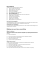
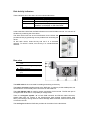
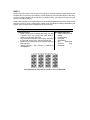
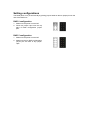
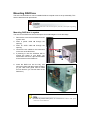
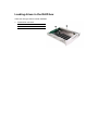
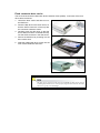
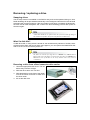
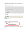
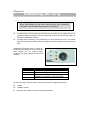
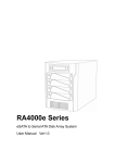
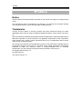
Preface
P
Prre
effa
ac
ce
e
Notice
Product features and specifications described in this manual are subject to change without
notice.
The manufacturer shall not be liable for any damage, or for the loss of information resulting
from the performance or use of the information contained herein.
Trademarks
Accusys and the names of Accusys products and logos referenced herein are either
trademarks and/or service marks or registered trademarks and/or service marks of Accusys,
Inc.
Microsoft, Windows, Windows NT, MS-DOS are either trademarks or registered trademarks of
Microsoft Corporation. Intel and Pentium are registered trademarks of Intel Corporation.
Other product and company names mentioned herein may be trademarks and/or service
marks of their respective owners.
All contents of this manual are copyrighted by Accusys, Incite information contained herein is
the exclusive property of Accusys, Inc. and shall not be copied, transferred, photocopied,
translated on paper, film, electronic media, or computer-readable form, or otherwise
reproduced in any way, without the express written permission of Accusys Inc.
© Copyright 2004 Accusys, Inc.
All rights reserved.
This manual version 1.0
About this manual
Intended user
This manual is designed and written for users of the ACS-76130 RAID controller. The user
should ideally be familiar with RAID planning and data storage operations and have
experience in electronic or computer engineering.
Organization of the manual
This manual consists of the following sections:
Chapter 1:
Introduction provides details of key features, checklists of package contents
and user requirements, and an overview of the RAID box and its features.
Chapter 2:
Before you begin contains all the information you need to decide whether to
set up a RAID 0 or RAID 5 array and lists important pre-installation notices.
Chapter 3:
Setting up the controller guides you through process of installing ACS-76130
in a system or externally and explains how to replace drives.
Chapter 4:
Initializing the array explains how to launch the automatic initialization
process.
Chapter 5:
Formatting tells you how partition and format the array so that your system can
start using it.
Appendix A: FAQ helps you deal with encountered problems in the form of Q&A.
Appendix B: Glossary defines relevant technical terms used in this manual.
Appendix C: Specifications list technical specification of ACS-76130.
Appendix D: Regulatory Information provides information of related certification and
standards.
Appendix E: Contact Us lists contact details of Accusys business units around the world.
Preface
Using this manual
This guide contains all the information you need to set up and start using your RAID controller
and to monitor its performance in real time. The setup process will follow these steps:
Prepare: Familiarize yourself with the features and capabilities of
ACS-76130 (Chapter 1)
Decide whether to set up a RAID 0 or RAID 5 array
(Chapter 2)
Configure:
Set up the controller (Chapter 3)
Install: Attach the necessary cables and either mount the RAID
box inside your system or set up the RAID box externally
(Chapter 3)
Initialize: Initialize the array (Chapter 4)
Format: Partition the array to enable your computer’s operating
system to begin using it (Chapter 5)
Format the array (Chapter 5)
When you have reached this point, your RAID controller will be ready for use. To get the most
from ACS-76130, you should also set up the ACSView GUI on your system. With this browser
you can monitor the status of your array at any time and from any computer on your LAN. You
will find full installation instructions and information on the monitoring capabilities of ACSView
in the ACS-76130 ACSView User’s Manual. Ask your vendor for details.
Guide to Conventions
Important information that users should be aware of is indicated with the following icons:
This icons indicates the existence of a potential hazard that could result in
personal injury, damage to your equipment or loss of data if the safety
instruction is not observed.
This icon indicates useful tips on getting the most from your RAID controller.
Important terms, commands and programs are put in Boldface font.
Screen text is given in screen font.
Table of Contents
T
Ta
ab
blle
eo
off C
Co
on
ntte
en
ntts
s
P
R
P
RE
EF
FA
AC
CE
E ................................................................................................................. 1
PREFACE
NOTICE....................................................................................................................... 1
TRADEMARKS ............................................................................................................ 1
ABOUT THIS MANUAL ................................................................................................. 2
Intended user........................................................................................................ 2
Organization of the manual ................................................................................. 2
USING THIS MANUAL .................................................................................................. 3
GUIDE TO CONVENTIONS ........................................................................................... 4
T
A
F
O
T
AB
BL
LE
EO
O
FC
C
ON
NT
TE
EN
NT
TS
S .................................................................................. 5
TABLE
OF
CONTENTS
CHAPTER 1 .................................................................................................................... 7
IIINTRODUCTION.................................................................................................
N
NT
TR
RO
OD
DU
UC
CT
TIIO
ON
N
7
OVERVIEW ................................................................................................................. 7
KEY FEATURES ........................................................................................................... 8
Hard drive hot swapping ..................................................................................... 8
Automatic drive rebuilding .................................................................................. 8
MAKING SURE YOU HAVE EVERYTHING ...................................................................... 8
What's in the box.................................................................................................. 8
What else you need............................................................................................... 8
FAMILIARIZING YOURSELF WITH THE CONTROLLER ................................................... 9
Overview .............................................................................................................. 9
Front view ............................................................................................................ 9
Rear view ........................................................................................................... 10
CHAPTER 2 .................................................................................................................. 11
B
E
O
E
B
EF
FO
OR
RE
EY
Y
OU
UB
B
EG
GIIN
N .................................................................................... 11
BEFORE
YOU
BEGIN
PRE-INSTALLATION PLANNING ................................................................................. 11
Introduction to RAID levels ............................................................................... 11
RAID 0 ............................................................................................................... 12
RAID 5 ............................................................................................................... 13
PRE-INSTALLATION NOTICES .................................................................................... 14
CHAPTER 3 .................................................................................................................. 15
S
E
P
H
O
S
ET
TT
TIIN
NG
GU
U
PT
T
HE
EC
C
ON
NT
TR
RO
OL
LL
LE
ER
R
SETTING
UP
THE
CONTROLLER.......................................................
15
INSTALLATION FLOWCHART ..................................................................................... 15
SETTING CONFIGURATIONS ...................................................................................... 16
RAID 0 configuration......................................................................................... 16
RAID 5 configuration......................................................................................... 16
MOUNTING RAID BOX ............................................................................................. 17
Mounting RAID box in system ........................................................................... 17
LOADING DRIVES IN THE RAID BOX......................................................................... 18
Fixed connector drive carrier ............................................................................ 19
REMOVING / REPLACING A DRIVE ............................................................................. 20
Swapping drives ................................................................................................. 20
What if a disk fails?............................................................................................ 20
Removing a drive from a fixed connector drive carrier..................................... 20
FIRMWARE UPDATING STEPS.............................................................................. 21
CHAPTER 4 .................................................................................................................. 23
IIINITIALIZING
N
H
R
NIIT
TIIA
AL
LIIZ
ZIIN
NG
GT
T
HE
EA
A
RR
RA
AY
Y .................................................................... 23
THE
ARRAY
APPENDIX A ................................................................................................................ 25
F
A
F
AQ
Q ............................................................................................................................. 25
FAQ
APPENDIX B ................................................................................................................ 26
G
L
G
LO
OS
SS
SA
AR
RY
Y ........................................................................................................... 26
GLOSSARY
APPENDIX C ................................................................................................................ 28
S
P
S
PE
EC
CIIF
FIIC
CA
AT
TIIO
ON
NS
S ............................................................................................ 28
SPECIFICATIONS
APPENDIX D................................................................................................................ 29
R
E
N
NF
FO
OR
RM
MA
AT
TIIO
ON
N ........................................................... 29
R
EG
GU
UL
LA
AT
TO
OR
RY
Y IIINFORMATION
REGULATORY
APPENDIX E ................................................................................................................ 30
C
O
S
C
ON
NT
TA
AC
CT
TU
U
S ...................................................................................................... 30
CONTACT
US
ACCUSYS, INC. ......................................................................................................... 30
ACCUSYS U.S.A., INC. ............................................................................................. 30
ACCUSYS KOREA, INC.............................................................................................. 30
ACCUSYS CHINA, INC............................................................................................... 30
世仰科技北京代表处 ............................................................................................. 31
ACCUSYS EU, BV. ................................................................................................... 31
Chapter 1 – Introduction
Chapter 1
IIn
nttrro
od
du
uc
cttiio
on
n
This chapter introduces the features and capabilities of
ACS-76130.
You will find:
A full introduction to your ACS-76130 controller
Details of key features
A checklist of package contents
A checklist of what else you need to start installation
An overview of the RAID box and its features, including
connectors, LEDs and jumpers
Overview
Congratulations on your selection of the Accusys 76130 (ACS-76130). The ACS-76130 is a
high-performance and extremely flexible RAID (Redundant Array of Independent/Inexpensive
Disks) controller. RAID is a storage technology used to improve the processing capabilities of
a storage system, providing a combination of reliability and performance.
The ACS-76130 is the ultimate approach to a flexible RAID solution. It can manage two
different RAID levels (0 and 5), with three SATA disks in a single RAID group. With a
cost-effective SATA approach, supporting Ultra DMA mode, the ACS-76130 strips data to
three disk drives simultaneously, and delivers optimized performance, comparable to more
costly SCSI based solutions.
Featuring intelligent online recovery, the ACS-76130 lets you hot swap a failed drive: data will
automatically be rebuilt to the new drive without any system down time. If a RAID 5 array
exists and one SATA disk drive fails, data is secured by the other drives, and an alarm sounds
to alert you. RAID 5 rebuild will proceed automatically (during power on) as soon as you lock
the disk carrier. If a RAID 0 array fails, there is no way to recover the data of the RAID system.
You should proceed by reconfiguring the new RAID with a new SATA disk.
The ACS-76130 RAID box features a user-friendly rack design that lets you easily install three
drives. Each drive carrier supports a one-inch high 3.5-inch form factor drive. Security is
provided by a key-locking system that prevents unauthorized access to each disk drive.
Key features
The ACS-76130 supports the following features:
Support 3 SATA-I disk channels.
Support one SATA-I host channel
Support RAID level 0 and 5
Drives are hot swappable
Hot transparent and OS independent
Fan cooler (Ball bearing type)
Support ATA-6 big drive
Key locking to prevent unauthorized access to the disk drives
Audible alarm on drive failure
Automatic drive failure detection
Automatic online rebuilding
Audible alarm on drive failure
Battery backup for disk rebuild status
Hard drive hot swapping
Hot Swapping allows for the removal and installation of disk drives without the need to power
down the system while ACS-76130 is configured as a RAID 5 array.
Automatic drive rebuilding
If a member drive in a RAID 5 array is replaced on-line, the controller will automatically start to
rebuild data to the new drive.
Making sure you have everything
What's in the box
Some vendors may ship certain components as standard, while other vendors treat the same
component as optional. In its most basic configuration, your package should include the
following:
ACS-76130 RAID box
ACS-76130 Controller User’s Manual and GUI management software
Three disk drive carriers with key locks
Disk drive mounting screws
Two keys for drive carriers (identical)
What else you need
In order to setup a working system the following user-supplied items are required:
System with SATA Interface
Case with two half-height 5 ¼” drive bays with front bezel access
One SATA channel cable connector
One free power supply connector at least
One 3-pin RS232 cable connector (data connection for GUI interface, if required)
Chapter 1 – Introduction
Familiarizing yourself with the controller
Overview
The RAID box has three drive carriers, accessed from the front.
The sides of the box each feature a guide rail channel and mounting screw holes to enable
the box to be secured inside a computer case.
The connectors and jumpers are located on the rear panel.
Front / Drive carriers
Guide rail channel
Holes for mounting screws
Rear / Connectors & jumpers
Front view
Three Drive Carriers
Disk Activity Indicators
Drive Carrier Lock
Each drive carrier can hold a one-inch high 3.5-inch form factor SATA disk drive. This makes it
easy to hot swap a drive in the event of a failure, without affecting the status of the remaining
drives.
Drive Carrier Lock – Unlocked
orientation
Drive Carrier Lock – Locked
orientation
Green Disk Activity Indicator
Amber Disk Activity Indicator
Red Disk Activity Indicator
Disk Activity Indicators
These indicators show the status of each individual disk drive.
Indicator
Green
Amber
Red
Red Flashing
Disk Activity
Disk drive is properly installed and locked
Disk drive is being accessed
Disk drive is not present, is not properly
installed, is unlocked, or disk has failed
Disk drive is rebuilding data
In the event that a drive fails, the Red indicator turns on and an alarm sounds. You can turn off
the alarm by unlocking the drive carrier.
The drive carrier lock acts as an On/Off switch for the drives and
provides security by preventing non-key holders from accessing the
drives.
To lock each carrier, insert the key and turn it in a clockwise
direction. To unlock a carrier, turn the key in a counterclockwise
direction.
Rear view
Connector for SATA interface
cable
RAID level configuration jumper
pins
Power connector
3-pin RS232 connector (Terminal
port)
Cooling fan vent
The SATA cable is the route used for reading and writing to the array.
The power connector supplies power to the RAID box. In order to provide stable power, we
recommend to connect both power connectors on the RAID box.
The 3-pin RS-232 cable is used for remote monitoring of ACS-76130. The RS-232 port is
configured with DTE and PC compatible pin assignments.
There is a triangular symbol “▲” on both PCB connector and RS-232 cable connector,
please make sure you connect in the right direction (both triangle symbols match each
other). Connecting in wrong direction will not damage RAID controller, however the terminal
or GUI will not work.
The cooling fan inside the RAID box provides air circulation for the disk drives.
Chapter 2 – Before you begin
Chapter 2
B
Be
effo
orre
ey
yo
ou
ub
be
eg
giin
n
This chapter contains includes all the information you need to
decide which RAID level to use and to prepare for installation.
You will find:
A full introduction to and comparison of RAID levels 0 and 5
Important notices on the safe operation and installation of
ACS-76130
Pre-installation planning
Introduction to RAID levels
The ACS-76130 can support the following RAID levels: 0 and 5. Which is the right level for
you? The answer depends on the application it is used for.
RAID Level 0 offers high transfer rates, and is ideal for large blocks of data where speed is of
importance. Computer Aided Design, Graphics, Scientific Computing, Image and Multimedia
applications are all good examples. If one drive in a RAID 0 array fails however, the data on
the whole array is lost.
RAID Level 5 arrays offer high I/O transaction rates, and are the ideal choice when used with
on-line transaction processing applications, such as those used in banks, insurance
companies, hospitals, and all manner of office environments. These applications typically
perform large numbers of concurrent requests, each of which makes a small number of disk
accesses. If one drive in a RAID 5 array fails, the lost data can be rebuilt from data on the
functioning disks.
Further information on RAID concepts can be found in Appendix B, Glossary.
RAID 0
RAID 0 links each drive in the array as one huge drive. Storage capacity is determined by the
smallest drive in the array. That capacity is then applied to format all other drives in the array.
If using a 40 GB, 60 GB, and 50 GB drive in a RAID 0 array, your system will see one huge
drive of 120 GB (40 GB×3).
RAID 0 offers double or more performance under sustained data transfers when one drive per
ATA port is used. In such a configuration, unlike SCSI, ATA drives are always available to the
system. SCSI requires more management of the SCSI bus.
RAID 0: Striped disk array without fault tolerance
Characteristics:
Recommended use:
RAID 0 implements a striped disk array, the data
is broken down into blocks and each block is
written to a separate disk drive.
I/O performance is greatly improved by spreading
the I/O load across many channels and drives.
Fastest and most efficient array type but offers no
fault-tolerance.
Storage capacity = (No. of disks) × (capacity of
smallest disk)
Video production and
editing
Image editing
Pre-press
applications
Any
application
requiring
high
bandwidth
Arrangement of data blocks saved on a Level 0 RAID
Chapter 2 – Before you begin
RAID 5
RAID 5 uses a mathematical expression that compares data from two drives and calculates a
third piece of data called “parity”. Should one of the drives fail, parity data can be used to
rebuild the failed data. Under RAID 5, parity data is stored across all drives in the array. This
maximizes the amount of storage capacity available from all drives in the array while still
providing data redundancy.
RAID 5: Independent data disks with distributed parity blocks
Characteristics:
Recommended use:
Each entire data block is written on a data disk.
Parity for blocks in the same rank is generated
on Writes, recorded in a distributed location and
checked on Reads.
Highest Read data transaction, medium Write
data transaction rate.
Relatively low ratio of ECC (Parity) disks to data
disks means high efficiency (compared to other
RAID levels).
Good aggregate transfer rate.
Storage capacity = (No. of disks – 1) × (capacity
of smallest disk)
File and application
servers
Database servers
WWW, E-mail and News
servers
Intranet servers
Most versatile Raid level
Arrangement of data and parity blocks saved on a Level 5 RAID
Pre-installation notices
Before starting any kind of hardware installation, please ensure that all power
switches have been turned off and all power cords disconnected to prevent
personal injury and damage to the hardware.
To avoid overheating, ACS-76130 should be installed in a well-ventilated area
and in such a way that sufficient airflow is maintained across the controller
chips.
Static electricity can damage electronic components. To guard against such
damage:
Work in a static-free environment
Wear a grounded anti-static wrist strap
Store uninstalled components in anti-static bags
Handle PCBs by their edges and avoid touching chips and connectors.
Environmental requirements: Temperature: 0-50C
Humidity: 5-95%, non-condensing
Altitude: Sea level to 10,000 ft
Chapter 3
S
Se
ettttiin
ng
gu
up
p tth
he
ec
co
on
nttrro
olllle
err
This chapter explains how to:
Set RAID level on RAID box
Install the RAID controller in a system or externally
Load hard drives into ACS-76130
Swap drives
Installation flowchart
Installation of ACS-76130 is simple. This chapter will lead you though the following steps:
Install
controller
When the controller is fully configured, connect a power and
SATA cable and install it either in a system or externally.
Load hard
When the controller is installed, load a hard drive into each
of the drive carriers
drives
Setting configurations
The RAID (level 0 or 5) is set manually by placing jumper heads on the ten jumper pins on the
rear of the RAID box.
RAID 0 configuration
1. Make sure the power is turned off.
2. Place two jumper caps over the top
pairs of RAID configuration jumper
pins.
RAID 5 configuration
1. Make sure the power is turned off.
2. Make sure the ten RAID configuration
jumper pins are clear of any jumper
caps.
Mounting RAID box
The ACS-76130 RAID box can be installed inside a computer case or set up externally. This
section describes both procedures.
Turn off and disconnect all electrical power from the system before beginning
installation.
Mounting RAID box in system
The ACS-76130 RAID box fits into the space of two half-height 5¼-inch drive bays.
1. Remove the cover and front bezel from the
system case.
2. Feed a power cable
opening.
through the
3. Feed an SATA cable
opening.
through the
4. Connect the two cables to the connectors
on the rear of the RAID box.
5. If planning to use the ACSView GUI to
monitor the status of your RAID, you
should also connect a 3-pin RS-232 cable
to the terminal on the RAID box.
6. Insert the RAID box into the bay, and
secure it in place with the screws provided.
(If your case uses guide rails to install
5¼-inch devices, you can use them on the
RAID box.)
In order to provide stable power, we recommend to connect both power
connectors on the RAID box.
Loading drives in the RAID box
There are one type of drive carrier available:
1. Fixed SATA connector
Drive Carrier
Fixed SATA Connector
Fixed connector drive carrier
The ACS-76130 should be fitted with three hard disk drives (HDDs). Load each drive into a
drive carrier as follows:
1. Unlock the drive carrier and slide it out of
the RAID box.
2. Place the disk drive in the drive carrier, so
that the SATA connector is lined up with
the connector inside the carrier.
3. Carefully push the disk drive so that the
drive’s SATA connector is seated securely
into the SATA connector in the disk carrier.
4. Secure the disk drive by screwing it to the
drive carrier case.
5. Slide the loaded disk drive carrier into the
ACS-76130 RAID Box and lock it.
The disk carrier connector at the back of each RAID box disk carrier slot can
be damaged if the disk carrier is not properly aligned when inserted. Insert the
disk carrier gently to avoid damage.
Removing / replacing a drive
Swapping drives
The hot swap function is available on the RAID 5 array and can be operated during run time.
RAID rebuilding will be processed automatically in the background and the ACS-76130 RAID
subsystem will record its progress. If the host system is shut down or powered off abnormally,
the ACS-76130 RAID subsystem will continue the disk rebuilding process after power is
turned on again.
A hard disk should not be replaced when the system is turned off. Doing so
may leads to loss of data. Always hot swap disks in a RAID5 array.
What if a disk fails?
If a disk drive fails, or a key switch is turned off, the red disk activity indicator of its disk carrier
will light and the alarm will sound. When this happens, you can replace the failed SATA disk
with a new one, then turn the key switch on.
The failure or removal of a single drive in a RAID5 array will not lead to
failure of the array. The failure or removal of a single drive in a RAID0 array
will lead to loss of all data on the array and the entire array must be
re-initialized.
Removing a drive from a fixed connector drive carrier
1. Unlock the appropriate disk carrier. The red
disk activity indicator will light.
2. Slide the drive carrier out of its slot.
3. Slide the disk drive to the front of the carrier
so that the SATA connector is freed from
the drive carrier.
4. Lift out the disk drive.
Firmware updating steps
1. Ensure the ACS-76130 is turned off.
2. Connect the RS-232 cable to the RS-232 3pin port (Please refer the page 10 “Rear
View”), and connect the other end to one of the host computer’s COM port.
3. Launch HyperTerminal from the host computer: Start > Programs > Accessories >
Communications > HyperTerminal.
4. Select COM1 or COM2 from the Connect using: dropdown menu, depending on which
port is connecter to ACS-76130.
5.
The COM properties dialog box will appear. Set the following values:
Bit per second: 19200
Data bits: 8
Parity: None
Stop bits: 1
Flow Control: Xon/Xoff
6.
Turn on the ACS-76130 and press the ESC button on the host computer keyboard. The “>>>”
prompt will appear.
7.
Type in the command “download” to go to the firmware download mode, then type “1” to
download code (Firmware or Bootcode).
>>> download
restart … 01 GPIO 01 AAA 01 01
========= 76 Download Mode =========
Enter ‘1’
to Download Code (Firmware, Bootcode)
‘ESC’ exit
8.
Locate the updates firmware file to send. For HyperTerminal, go to the Transfer menu and select
Send Text File.
9.
Send the firmware file as a text file. The file will start to download.
Caution
Do not turn off the system or interrupt program
during firmware-updating procedure.
10. When the file has been downloaded, after ACS-76130 restarted, the firmware-updating procedure
is finished.
Chapter 4
IIn
niittiia
alliiz
ziin
ng
g tth
he
ea
arrrra
ay
y
Once ACS-76130 is set up and connected, the array should be
initialized. The initialization process is automatic.
If system power is off and ACS-76130 is fully set up, simply turn on system power. The
system will detect the presence of ACS-76130 and ACS-76130 will check the status of
the HDDs. Initialization will start.
If system power is already on, key off then key on each of the drives in turn. You should
wait for the green disk activity indicator to light for each drive before keying on the next
drive.
Initialization and RAID status is shown by
the disk activity indicators. Once a drive has
been located and its working status
confirmed, the green indicator for that drive
will light.
Indicator
Green
Amber
Red
Red Flashing
Disk Activity
Disk drive is properly installed and locked
Disk drive is being accessed
Disk drive is not present, is not properly
installed, is unlocked, or disk has failed
Disk drive is rebuilding data
If a red disk activity indicator shows, check to make sure the appropriate drive is:
Locked
Installed correctly
Not faulty (if necessary, the drive should be replaced).
During array initialization, the following will be observed:
Indicator
Green
Status
Solid
Amber
Solid
Red
Flashing
Alarm
Intermittent
If system power is turned off midway through array initialization, the process
will continue from its point of interruption when power returns.
Risk of Explosion if Battery is replaced by an Incorrect Type. Dispose of Used
Batteries According to the Instructions
Appendix A – FAQ
Appendix A
F
FA
AQ
Q
If you encounter a problem while using the ACS-76130, check this section for help.
1. When I lock a drive carrier with a disk drive in place, the red disk activity indicator
turns on and an alarm beep sounds. Why?
(a) Make sure you firmly connect the SATA connector of the HDD to their counterparts
inside the drive carrier and try again. If this does not solve the situation, go to (b).
(b) Change the disk drive with a new one and try again.
(c) Exchange the top and bottom drive carriers and try again to determine if the carrier
itself is faulty.
(d) If all of the above steps fail, contact your vendor.
2. How can I turn off the alarm beep sound when there is a hard disk failure?
Unlock the drive carrier of the failed disk. This will turn off the alarm beep sound.
3. I have connected the RAID controller, but it does not appear in the motherboard
BIOS. Why?
Ensure that an array is initialized.
Appendix B
G
Gllo
os
ss
sa
arry
y
Array
See Disk Array.
Array Management Software
The body of software that provides common control and management for a disk array. Array
Management Software most often executes in a disk controller or intelligent host bus adapter,
but may also execute in a host computer. When it executes in a disk controller or adapter, Array
Management Software is often referred to as Firmware.
Cache
Controller memory used to speed up data transfer to and from a disk.
Disk Array
A collection of disks from one or more commonly accessible disk controllers, combined with a
body of Array Management Software. Array Management Software controls the disks and
presents them to the array operating environment as one or more virtual disks.
Firmware
See Array Management Software.
Host Computer
Any computer system to which disks are directly attached and accessible for I/O. Mainframes,
and servers, as well as workstations and personal computers, can all be considered host
computers in the context of this manual, as long as they have disks attached to them.
Parity
Parity information is redundancy information calculated from actual data values. If any single
piece of data is lost, the data remaining and the parity information can be used together to
compute the lost data. Parity information can either be stored on a separate, dedicated drive, or
be mixed with the data across all the drives in the array.
RAID (Redundant Array of Independent / Inexpensive Disks)
Appendix B – Glossary
A disk array in which part of the storage capacity is used to store redundant information about
user data stored on the remainder of the storage capacity. The redundant information enables
regeneration of user data in the event that one of the array member disks or the access path to
it fails. See Parity. Different RAID levels offer different data throughput speeds and fault
tolerance (data redundancy). RAID 0 does not feature redundant information but is nonetheless
considered a special type of RAID.
Appendix C
S
Sp
pe
ec
ciiffiic
ca
attiio
on
ns
s
Host interface
Disk interface
RAID levels supported
Form factor
Dimensions
Weight
Hot swap
Beeper alarm
FAN
One SATA-I
SATA-I (Support SATA-II but run in SATA-I)
0 and 5
Two half height 5 ¼ inch
W5.75×D8.84×H3.35 (inch)
3.96 (lb)
Yes
(Rebuilding is transparent & automatic)
Yes, built-in buzzer on board
Rated Speed: 4700RPM+/- 400RPM
Noise Level: 35dB(A)
Specifications are subject to change without notice.
Appendix D – Regulatory information
Appendix D
R
Re
eg
gu
ulla
atto
orry
y iin
nffo
orrm
ma
attiio
on
n
FCC Statement
This equipment has been tested and found to comply with the limits for a Class B digital device,
pursuant to Part 15 of FCC Rules. These limits are designed to provide reasonable protection
against harmful interference in a residential installation. This equipment generates, uses, and
can radiate radio frequency energy and, if not installed and used in accordance with the
instructions, may cause harmful interference to radio communications. However, there is no
guarantee that interference will not occur in particular installation. If this equipment does cause
harmful interference to radio or television reception, which can be determined by turning the
equipment off and on, the user is encouraged to try to correct the interference by one or more of
the following measures:
1. Reorient or relocate the receiving antenna.
2. Increase the separation between the equipment and receiver.
3. Connect the equipment into an outlet on a circuit different from that to which the receiver is
connected.
4. Consult the dealer or an experienced radio/television technician for help.
The changes or modifications not expressly approved by the party responsible for compliance
could void the user’s authority to operate the equipment.
Shielded interface cables, if any, must be used in order to comply with the emission limits.
CE Mark
This equipment is in conformity with the EMC directive.
UL Listed
This equipment meets UL's safety requirements.
Appendix E
C
Co
on
ntta
ac
ctt U
Us
s
Accusys, Inc.
•
5F., No.38, Taiyuan St., Jhubei City, Hsinchu County 30265, Taiwan R.O.C.
•
Tel : +886-3-560-0288
•
Fax : +886-3-560-0299
•
http://www.accusys.com.tw/
•
e-mail : [email protected]
Accusys U.S.A., Inc.
•
46710 Fremont Blvd. Fremont, CA 94538, U.S.A.
•
Tel:+1-510-661-0800
•
Fax:+1-510-661-9800
•
Toll-free number:+1-866-277-5888
•
http://www.accusysusa.com/
•
e-mail : [email protected], [email protected]
Accusys Korea, Inc.
•
Baegang B/D 5F Shinsa-Dong 666-14 Kanggnam-Gu, Seoul, Korea
•
Tel : (02)6245-9050
•
Fax : (02)3443-9050
•
http://www.accusys.co.kr/
•
e-mail : [email protected]
Accusys China, Inc.
•
#1701, Blk B, Horizon International Tower, No. 6 Zhichun Street, Haidian District,
Beijing, China
•
China Postal Code:100088
•
Tel: +86-10-82800080 /81 /82/ 83
•
Fax: +86-10-82800784
•
Web: www.accusys.com.cn
•
Sales: [email protected]
•
Support: [email protected]
Appendix E – Contact Us
世
世仰
仰科
科技
技北
北京
京代
代表
表处
处
•
地址: 北京市海淀区知春路 6 号 锦秋国际大厦 B 座 1701
•
邮编: 100088
•
电话: +86-10-82800080 /81 /82 /83
•
传真: +86-10-82800784
•
网址: www.accusys.com.cn
•
Mail: [email protected]
•
Support: [email protected]
Accusys EU, BV.
•
Columbusstraat 22-26, Distripark Eemhaven, 3165 AD Rotterdam, Netherlands
•
Tel : +31-10-2995761
•
Fax : +31-10-4292194
•
Http://www.accusyseu.com
•
e-mail : [email protected]