1
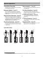
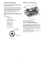
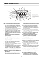
Logix 764
Operation Manual
Models: 255
Twin Alternating
Twin Parallel
Single with Remote
Regeneration Start
Multi-Single Tank with
Lockout
Table of Contents
Safety Information . . . . . . . . . . . . . . . . . . . . . . . . . . . . . . . . . . . . . . . . . . . . . . 3
How To Use This Manual . . . . . . . . . . . . . . . . . . . . . . . . . . . . . . . . . . . . . . . . . 4
Location Selection . . . . . . . . . . . . . . . . . . . . . . . . . . . . . . . . . . . . . . . . . . . . . . 9
Outdoor Locations . . . . . . . . . . . . . . . . . . . . . . . . . . . . . . . . . . . . . . . . . . . . . . 7
Installation . . . . . . . . . . . . . . . . . . . . . . . . . . . . . . . . . . . . . . . . . . . . . . . . . . . . 9
Location Selection
Water Line Connection
Drain Line Connection
Brine Line Connection
Brine Tank Overflow Line Connection
Electrical Connection
9
9
9
10
10
11
Disinfection of Water Conditioning Systems . . . . . . . . . . . . . . . . . . . . . . . . .12
System Operation . . . . . . . . . . . . . . . . . . . . . . . . . . . . . . . . . . . . . . . . . . . . .13
Cycle Water Flows . . . . . . . . . . . . . . . . . . . . . . . . . . . . . . . . . . . . . . . . . . . . .13
Camshaft Cycle Positions . . . . . . . . . . . . . . . . . . . . . . . . . . . . . . . . . . . . . . .14
764 Control Operation . . . . . . . . . . . . . . . . . . . . . . . . . . . . . . . . . . . . . . . . . .14
Display Icons & Cursors . . . . . . . . . . . . . . . . . . . . . . . . . . . . . . . . . . . . . . . .15
Keypad — Buttons . . . . . . . . . . . . . . . . . . . . . . . . . . . . . . . . . . . . . . . . . . . . .16
Placing Water Conditioning System Into Operation. . . . . . . . . . . . . . . . . . . .17
Level l Programming - 764 Control with 255 Valve, 8 Cycle Conditioner. . . .19
Quick Cycling the Control 255L and 255P
Quick Cycling the Control for 255A Systems
To Place the 255 Alternating System into Operation:
20
21
21
In Service Display . . . . . . . . . . . . . . . . . . . . . . . . . . . . . . . . . . . . . . . . . . . . .23
Programming Overview . . . . . . . . . . . . . . . . . . . . . . . . . . . . . . . . . . . . . . . . .23
Level II Programming – P Values. . . . . . . . . . . . . . . . . . . . . . . . . . . . . . . . . .24
Programming the Lockout Feature . . . . . . . . . . . . . . . . . . . . . . . . . . . . . . . .25
Level lll Cycle Programming – C Values . . . . . . . . . . . . . . . . . . . . . . . . . . . .27
Level IV Viewing History - H Values. . . . . . . . . . . . . . . . . . . . . . . . . . . . . . . .28
Program Reset . . . . . . . . . . . . . . . . . . . . . . . . . . . . . . . . . . . . . . . . . . . . . . .29
Manual Regeneration Options . . . . . . . . . . . . . . . . . . . . . . . . . . . . . . . . . . . .30
Regeneration Modes for Parallel Systems . . . . . . . . . . . . . . . . . . . . . . . . . .31
Wiring Diagrams . . . . . . . . . . . . . . . . . . . . . . . . . . . . . . . . . . . . . . . . . . . . . .32
Parts Lists . . . . . . . . . . . . . . . . . . . . . . . . . . . . . . . . . . . . . . . . . . . . . . . . . . .34
255 Exploded View & Parts List
Bypass Valve and Turbine Adapter
Manifold Kits
34
36
37
Troubleshooting . . . . . . . . . . . . . . . . . . . . . . . . . . . . . . . . . . . . . . . . . . . . . . .38
2
Safety Information
This water conditioner’s control valve conforms to UL/
CE Standards. Generic valves were tested and certified
for compliance as verified by the agency listing.
• Do not allow this water conditioning system to
• Please review the entire Installation and Operation
• Operating ambient temperature: 34° to 120°F
freeze. Damage from freezing will void this water
conditioning system’s warranty.
(1° to 49°C).
Manual before installing the water conditioning
system.
• Operating water temperature: 34° to 100°F
(1° to 38°C).
• As with all plumbing projects, it is recommended
that a trained professional water treatment dealer
install the water conditioning system. Please follow
all local plumbing codes for installing this water
conditioning system.
• Operating water pressure range : 20 to 120 psi
(1.38 to 8.27 bar). In Canada the acceptable
operating water pressure range is 20 to 100 psi
(1.38 to 6.89 bar).
• This system will not make microbiologically unsafe
• Observe all warnings that appear in this manual.
• Keep the media tank in the upright position. Do not
water safe. Water that is unsafe must be treated
separately from this conditioner.
turn upside down or drop. Turning the tank upside
down or laying the tank on its side can cause media
to enter the valve.
• This water conditioning system is to be used only
for potable water.
• Inspect the water conditioning system for carrier
• Use only regenerants designed for water
shortage or shipping damage before beginning
installation.
conditioning. Do not use ice melting salt, block salt
or rock salt.
• Use only lead-free solder and flux, as required by
federal and state codes, when installing soldered
copper plumbing.
• Use caution when installing soldered metal piping
near the water conditioning system. Heat can
adversely affect the plastic control valve and
bypass valve.
• All plastic connections should be hand tightened.
Teflon1 tape may be used on connections that do
not use an O-ring seal. Do not use pipe dope type
sealants on the valve body. Do not use pliers or
pipe wrenches.
• Do not use petroleum-based lubricants such as
Vaseline, oils or hydrocarbon-based lubricants. Use
only 100% silicone lubricants.
• Use only the power transformer supplied with this
water conditioning system.
• All electrical connections must be completed
according to local codes.
• The power outlet must be grounded
• Install an appropriate grounding strap across the
inlet and outlet piping of the water conditioning
system to ensure that a proper ground is
maintained.
• To disconnect power, unplug the AC adapter from
its power source.
• Observe drain line requirements.
• Do not support the weight of the system on the
control valve fittings, plumbing, or the bypass.
1. Teflon is a trademark of E. I. duPont de
Nemours.
3
How To Use This Manual
Icons That Appear In This Manual
This installation manual is designed to guide the
installer through the process of installing and starting
water conditioning systems featuring the Logix 764
controller.
WARNING: Failure to follow this
instruction can result in personal injury or
damage to the equipment.
This manual is a reference and will not include every
system installation situation. The person installing this
equipment should have:
• Training in the 764 series control and the 255 valve.
• Knowledge of water conditioning and how to
Note: Helpful hint to simplify procedure.
The Logix 764 control can be installed on several type
valves that can have twin alternating, twin parallel or
single tank configuration. The section on Logix 764
start-up provides a simple explanation of the valve
types that are pre-programmed in the 764 control.
determine proper control settings.
• Adequate plumbing skills.
Breakout Tabs for Wiring
Valve Discs
One Piece Valve
Disc Spring
Camshaft
Optical Sensor
Control Module
Motor
Refill
Controller
Manifold
Connection
Outlet
Injector
and Cap
Drain
Regenerant Tank
Tube Connection
Check Ball
Inlet
Air Check
Figure 1 255 Valve Layout
4
Injector Screen
Filter
Locking Bar
Backwash Drain Control
Knockout Opening
for Wiring
LCD Display
SU MO TU
WE TH FR SA
Time/Day
Regeneration Time
Salt Amount
Front
x2
Capacity
Hardness
CPH
PM
MIN
g/L
KG
x100
Lbs/ft³
Down Button
No-Salt Detector
(Chlorine Generator)
Connection
Back
Manual Regen Button
Set Button
Up Button
AC Adapter
(low voltage)
Input
Multi Single Tank
Lockout & Remote
Regen/Start
Dry Contact Signal Input
Connection
Main Motor &
Optical Sensor
Connection
Extension Cable
Connection
Turbine Input
Figure 2 764 Controller Identification
Figure 3 Remote Start/Multi-Tank Lockout Cable
Figure 4 Twin Sensor Cable
Figure 5 Twin Cable Extension
5
Location Selection
Location of a water conditioning system is important.
The following conditions are required:
• Level platform or floor.
• Room to access equipment for maintenance and
adding regenerant (salt) to tank.
• Ambient temperatures over 34oF (1oC) and below
120oF (49oC).
• Water pressure below 120 psi (8.27 bar) and above
25 psi (1.7 bar).
• In Canada the water pressure must be below
100 psi (6.89 bar).
• Constant electrical supply to operate the controller.
• Total minimum pipe run to water heater of ten feet
(three meters) to prevent backup of hot water into
system.
• Local drain for discharge as close as possible.
• Water line connections with shutoff or bypass
valves.
• Must meet any local and state codes for site of
installation.
• Valve is designed for minor plumbing
misalignments. Do not support weight of system on
the plumbing.
• Be sure all soldered pipes are fully cooled before
attaching plastic valve to the plumbing.
6
Outdoor Locations
When the water conditioning system is installed
outdoors, several items must be considered.
• Moisture – The valve and control are designed for
use in NEMA 3 locations. Falling water should not
affect performance. The system is not designed to
withstand extreme humidity or water spray from
below. Examples are: constant heavy mist, near
corrosive environment, or upwards spray from
sprinkler.
Caution: This unit is for dry location use only unless
used with a Listed Class 2 power supply suitable for
outdoor use.
• Direct Sunlight – The materials used will fade or
discolor over time in direct sunlight. The integrity of
the materials will not degrade to cause system
failures. If it is necessary to locate the conditioner in
direct sunlight, an outdoor cover (PN 1267811) over
the valve and control is necessary. Valve skirts
(PN 1267808) are available if further protection is
required.
• Temperature – Extreme hot or cold temperatures
will cause damage to the valve or control. Freezing
temperatures will freeze the water in the valve. This
will cause physical damage to the internal parts as
well as the plumbing and conditioning resin. High
temperatures will affect the control. The display
may become unreadable but the control should
continue to function. When the temperature returns
to normal operating limits the display will re-appear.
A protective cover should assist with high
temperature applications.
• Insects – The control and valve have been
designed to keep all but the smallest insects out of
the critical areas. Any holes in the top plate can be
covered with duct tape. The top cover should be
installed securely in place.
• Wind – The cover, when properly installed on the
valve, is designed to withstand a 30 mph (48 Kph).
7
Unconditioned
water in
Conditioned
water out
Figure 6 Typical Plumbing for Twin Tank Systems.
PA S S
PA S S
BY
PA S S
BY
BY
BY
Unit in Service
PA S S
Unit in Bypass
Figure 7
8
Installation
flowing from a heat source to the conditioners is to
install an expandable accumulator tank before the hot
water heater. Always conform to local codes.
All plumbing must conform to local codes. The two
tanks should be plumbed to an interconnecting
manifold, Figure-6. It is highly recommended that
separate brine lines be used for each tank. It is
critical for the resin, resin volume, inlet piping, etc. to be
identical for both tanks.
• Do not locate the unit in an area where the ambient
temperature is ever below 34oF (1oC) or over
120oF (49oC).
• Maximum allowable water temperature is
100oF (38oC).
WARNING: Do not use tools to tighten plastic
fittings. Over time, stress may break the
connections. Hand tighten the nuts.
• Do not install the unit near acid or acid fumes.
• Do not expose the unit to petroleum products.
Water Line Connection
WARNING: Do not use petroleum grease on
gaskets when connecting bypass plumbing.
Use only 100% silicone grease products when
installing any Pentair Water brand valve. Nonsilicone grease may cause plastic components
to fail over time.
A bypass valve system must be installed to
accommodate occasions when the water conditioning
system must be bypassed for supplying hard water or
servicing. See Figures 7 and 8.
In Bypass
Not in Bypass
WARNING: The inlet water must be connected
to the inlet port of the valve. When replacing
valves, the inlet and outlet may be reversed.
Ensure that the plumbing is not installed in the
oppposite order. Tank media may be pushed
into the valve.
Conditioning
System
W t
WARNING: Filter media may need to be
properly conditioned before the filter is placed
into full operation. Consult the original
equipment manufacturer for proper procedure.
Conditioning
System
Figure 8
W t
Drain Line Connection
Note: Standard commercial practices are expressed
here. Local codes may require changes to the following
suggestions. Check with local authorities before
installing a water conditioning system.
Location Selection
The system should be above, and not more than 20 feet
(6.1 m) from a drain. Connect an appropriate fitting and
1/2-inch (1.3-cm) plastic tubing to the drain line
connection on the rear of the control valve.
• The following considerations must be taken into
account when selecting the location for the water
conditioning system.
• Locate the system as close to a drain as possible.
• If supplementary water treating equipment is
If the backwash flow is more than 5 gpm or if the unit is
located more than 20 feet (6.1 m) from the drain, use 3/
4-inch (1.9-cm) tubing for runs up to 40 feet (12.2 m).
Also, purchase appropriate fitting to connect the 3/4inch tubing to the 1/2-inch NPT drain connection.
required, make sure that adequate additional space
is available. Locate the brine tank in an accessible
place so that salt can be easily added.
• Do not install any system with less than 10 feet
If unit is located where the drain line must be elevated,
you may elevate the line up to 5 feet (1.5 m) providing
the run does not exceed 15 feet (4.6 m) and water
pressure at the conditioners is not less than 40 psi
(2.8 bar).
(3 m) of piping between the outlet of the
conditioners and the inlet of the water heater.
Water heaters can transfer heat down the cold
water pipe into the control valve. Hot water can
severely damage the conditioners.
Where drain line is elevated but empties into a drain
below the level of the control valve, form a 7-inch
(18-cm) loop at the far end of the line so that the bottom
A ten-foot (3-m) total pipe run (including bends, elbows,
etc.) is a reasonable distance to prevent hot water
damage. A positive way to prevent hot water from
9
of the loop is level with the drain line connection. This
will provide an adequate siphon trap.Where a drain
empties into an overhead sewer line, a sink-type trap
must be used. Secure the end of the drain line to
prevent it from moving (Figure-11).
Brine Line Connection
It is recommended that separate brine
lines be used for each tank.
A regenerant tank aircheck is not required when using a
255 valve with the built-in aircheck. Doing so will cause
premature checking and may result in hard water or
regenerant tank overflow. The 255 aircheck is available
standard with a 1/4" NPT tube compression fitting. The
use of Teflon tape is required on the 1/4" NPT
connection.
Figure 10 Brine Tank Drain
3. Attach a length of 1/2-inch (1.3-cm) tubing (not
supplied) to the fitting and run to the drain.
Install an appropriate fitting onto the 1/4-inch male NPT
connection on the air check (Figure-9), and install a
length of 3/8-inch polyethylene tubing between the air
check fitting and the brine pick-up tube at the brine tank.
If you are using a brine valve remove the ball in the air
check to avoid possible premature checking.
Note: Do not elevate the overflow line higher than
3 inches (7.6 cm) below the bottom of the overflow
fitting. Do not tie into the drain line of the control unit.
The overflow line must be a direct, separate line from
the overflow fitting to the drain, sewer, or tub. Allow an
air gap as in the drain line connection, Figure-10.
WARNING: Never insert drain line directly
into a drain, sewer line, or trap (Figure-11).
Always allow an air gap between the drain line
and the waste water to prevent the possibility
of sewage being back-siphoned into the
conditioner. Secure the end of the drain line to prevent
it from moving (Figure-11).
Air Gap
Regenerant Tank
Tube Connection
Check Ball
Air Check
Drain
Figure 9
Note: Make sure that all fittings and connections are
vacuum tight so that premature checking does not take
place. Premature checking occurs when the ball in the
air check falls to the bottom before all brine is drawn
out of the brine tank.
Figure 11
Brine Tank
Normally one brine tank is needed for each tank. The
use of block salt or rock salt is not recommended. If a
brine shelf is used, two brine tanks are required. This is
due to the increased time needed to produce a
concentrated brine solution when using a salt shelf. If
rapid multiple exhaustions and regenerations are
anticipated, do not use a salt shelf even if two brine
tanks are used.
Brine Tank Overflow Line Connection
In the event of a malfunction, the brine tank overflow
connection directs overflow to the drain instead of
spilling it on the floor where it could cause water
damage. Complete the following steps to connect the
overflow fitting to the brine tank:
1. Locate the fitting hole on the side of the brine tank.
2. Insert the overflow fitting (not supplied) into the tank
and tighten with the plastic thumb nut and gasket as
illustrated in Figure-10.
10
Electrical Connection
Caution: This valve and control are for dry location
use only unless used with a Listed Class 2 power
supply suitable for outdoor use.
The 764 Series control operates on a 12-volt alternating
current power supply. This requires use of the Pentair
Water supplied AC adapter. A variety of AC adapters
are available from your supplier for different
applications. They include:
AC Adapter
Input
Voltage
Standard wallmount
120V 60 Hz
Outdoor rated
120V 60 Hz
Application
UL listed for
indoor
installations
UL listed for
outdoor
installations
Part
Number
1000811
1235448
120 VAC AC Adapters:
Make sure power source matches the rating printed on
the AC adapter.
Note: The power source should be constant. Be
certain the AC adapter is not on a switched outlet.
Power interruptions longer than 8 hours may cause the
controller to lose the time and day settings. When
power is restored, the control will display four dashes
(- - :- -) indicating that the day and time settings must
be re-entered
Note: Do not connect power by plugging in the
transformer at this time. Doing so may cause difficulty
in properly placing the unit into operation.
Caution: Plumbing cannot be used for electrical
grounding when metal inlet and outlet piping is
connected to a non-metal valve.
Connect the inlet and outlet piping together using a
grounding strap or clamp to establish continuity.
11
Disinfection of Water Conditioning Systems
Calcium Hypochlorite
The materials of construction in the modern water
conditioning system will not support bacterial growth,
nor will these materials contaminate a water supply.
During normal use, a conditioner may become fouled
with organic matter, or in some cases with bacteria from
the water supply. This may result in an off-taste or odor
in the water.
Calcium hypochlorite, 70% available chlorine, is
available in several forms including tablets and
granules. These solid materials may be used directly
without dissolving before use.
1. Dosage
Some conditioners may need to be disinfected after
installation and some conditioners will require periodic
disinfection during their normal life.
A. Two grains (approximately 0.1 ounce (3
mL) per cubic foot.
Depending upon the conditions of use, the style of
conditioner, the type of ion exchanger, and the
disinfectant available, a choice can be made among the
following methods.
2. Regenerant tank conditioners
A. Backwash the conditioner and add the
required amount of hypochlorite to the well
of the regenerant tank. The regenerant tank
should have water in it to permit the chlorine
solution to be carried into the conditioner.
Sodium or Calcium Hypochlorite
These materials are satisfactory for use with
polystyrene resins, synthetic gel zeolite, and
bentonites.
B. Proceed with the normal regeneration.
5.25% Sodium Hypochlorite
These solutions are available under trade names such
as Clorox1. If stronger solutions are used, such as those
sold for commercial laundries, adjust the dosage
accordingly.
1. Dosage
• Polystyrene resin; 1.2 fluid ounce (35.5 mL)
per cubic foot.
• Non-resinous exchangers; 0.8 fluid ounce
(23.7 mL) per cubic foot.
2. Regenerant tank conditioners
A. Backwash the conditioner and add the
required amount of hypochlorite solution to
the well of the regenerant tank. The
regenerant tank should have water in it to
permit the solution to be carried into the
conditioner.
B. Proceed with the normal regeneration.
1. Clorox is a trademark of the Clorox
Company.
12
System Operation
Treated Water (Downflow)
Repressurization – Cycle C4
Untreated water is conditioned as it flows through
the resin bed and up the riser.
Pressure is balanced in the valve before continuing
the regeneration.
Backwash (Upflow) – Cycle C1
Fast Rinse (Downflow) - Cycle C5
Flow is reversed by the control valve, directed
down the riser, up through the resin bed and sent
to drain. The bed is expanded and debris is flushed
to the drain.
Regenerant Draw (Downflow) – Cycle C2
Water passes through the resin bed and up
through the riser to drain. All remaining regenerant
residual is rinsed from the resin bed.
2nd Backwash (Upflow) - Cycle C6
1
Flow is identical to C1 Backwash. The resin is
reclassified.
Water passes through the injector and regenerant
is drawn from the regenerant tank. The regenerant
is directed to the resin bed. The hardness ions are
displaced by sodium ions. Regenerant draw is
completed when the air check closes.
2nd Rinse (Downflow) - Cycle C7
Flow is identical to C5 Fast Rinse. The resin bed is
rinsed to quality.
Slow Rinse (Downflow) – Cycle C31
Regenerant Refill – Cycle C8
Water flow moves the regenerant through the resin
at a specific rate and rinses to the drain. The resin
is regenerated.
Water is directed to the regenerant tank to create
regenerant for the next regeneration.
Cycle Water Flows
To Regenerant
Tank
From Regenerant
Tank
Service
Backwash
Regenerant Draw/
Slow Rinse
Repressurize
Fast Rinse
Refill
1. The camshaft does not change position between the C2 and C3 cycles. C3 is not displayed.
13
Camshaft Cycle Positions
Valve Disc Location/Function
The front end of the camshaft has an indicator cup. The
cup has slots in the outer edge and cycle numbers on
the inside face (Figure-12).
5 Rinse Drain
6 Backwash/Drain
Wiring
Breakouts
Remove the cover and look over the top of the 764
control to view the cycle numbers. The number at the
top indicates the current cycle position of the control
valve. The corresponding slot for the number is
positioned at the optical sensor, which is rotated
approximately 90 degrees out of phase.
Note: If electrical power is not available, the camshaft
can be rotated counterclockwise by hand if the motor is
removed.
4 Bypass
3 Outlet
2 Inlet
Cycle Indicators:
1 Regenerant
0 = Treated Water
1 = Backwash Cycle
Figure 13 255 Valve
2 = Regenerant Draw Cycle
3 = Slow Rinse Cycle
764 Control Operation
4 = System Pause
Power Loss Memory Retention
5 = Fast Rinse Cycle 1
The 764 control features battery-free Time of Day and
Day of Week retention during loss of power. A super
capacitor is designed to keep time for 8 to 24 hours
depending on the installation. If the super capacitor is
exhausted the Logix control will display four dashes
(- - :- -) immediately upon power up. The Time of Day
and Day of Week must be reset.
6 = 2nd Backwash
7 = 2nd Fast Rinse
8 = Regenerant Refill
Treated Water
Cycle Number
All other programmed parameters are stored in the
static memory and are retained.
Treated Water
Slot
Figure 12
14
Display Icons & Cursors
16
14
SU MO TU
13
8
10
9
7
2
1
WE TH FR SA DAYS
a
Time/Day
Regeneration Time
15
12
Salt Amount
x2
13
a
26
Capacity
Hardness
25
CHP
23
24
3
4
PM
MIN
g/L
KG
5
6
17
x100
Lbs/ft 3
22
21
Note: In normal operation and during programming,
only a few of the icons will actually be displayed.
20
19
a
If your Logix 764 controller was
purchased as a filter control, the
overlay will show: Time/Day,
Backwash Time, Backwash Length
and Capacity.
18
been called for. Also displayed (continuous) when
in regeneration.
1. This cursor is displayed when the days between
regeneration are being programmed (used with .5
to 99 day regeneration programming).
12. The display cursor is next to "SALT AMOUNT"
when programming the amount of regenerant. If
the controller is on a 3-cycle filter then backwash
time is programmed.
2. One of these cursors is displayed to indicate which
day will be programmed into the controller.
13. The display cursor is next to "REGENERATION
TIME" when programming the time of regeneration
and the days of regeneration.
3. "PM" indicates that the time displayed is between
12:00 noon and 12:00 midnight (there is no AM
indicator). PM indicator is not used if clock mode is
set to 24-hour.
14. The display cursor is next to "TIME/DAY" when
programming the current time and day.
4. When "MIN" is displayed, the value entered is in
minute increments.
15. The hourglass is displayed when the motor is
running. The camshaft should be turning.
5. When g/L is displayed, the value for regenerant
amount entered is in grams/Liter.
16. These cursors appear next to the item that is
currently displayed.
6. When "Kg" is displayed, the value entered is in
kilograms or kilograins.
17. X100 multiplier for large values.
18. When Lbs/ft3 is displayed the value for regenerant
amount entered is in pounds/cubic foot.
7. Four digits used to display the time or program
value. Also used for error codes.
19. Faucet is displayed when the current flow rate is
displayed. Control may show the faucet and "0",
indicating no flow.
8. Colon flashes as part of the time display. Indicates
normal operation (742 only).
9. Locked/unlocked indicator. In Level I programming
this is displayed when the current parameter is
locked-out. It is also used in Level II programming
to indicate if the displayed parameter is locked
(icon flashes) when controller is in Level I.
20. Maintenance interval display turns on if the months
in service exceed the value programmed in P11.
10. When "x2" is displayed, a second regeneration has
been called for.
22. History Values (H). The number displayed by #23
identifies which history value is currently displayed.
11. The recycle sign is displayed (flashing) when a
regeneration at the next time of regeneration has
23. Parameter (P). Displayed only in Level II
Programming. The number displayed by #23
identifies which parameter is currently displayed.
21. Used with #24, #25, and #26. Displays valve in
service, a sequence number or a value.
15
Programming Conventions
24. Cycle (C). The number displayed by #23 is the
current cycle in the regeneration sequence.
26. Capacity display—shows estimated system
capacity.
The 700 series controller is programmed using the
buttons on the keypad. The programming instructions
are described two ways whenever a section has keypad
input.
Keypad — Buttons
First, a table shows simplified instructions. Second, text
follows that describes the action. In each table:
25. Hardness setting
"Action" lists the event or action desired.
"Keys" are listed as:
UP for up arrow
DOWN for down arrow
SET for set
REGEN for regeneration
4
1
2
"Duration" describes how long a button is held down:
3
P/R for press and release
HOLD for press and hold
X sec for a number of seconds to press the button
and hold it down
Figure 14
1. DOWN arrow. Generally used to scroll down or
increment through a group of choices.
"Display" calls out the display icons that are visible.
2. SET. Used to accept a setting that normally
becomes stored in memory. Also used together
with the arrow buttons.
3. UP arrow. Generally used to scroll up or increment
through a group of choices.
4. Regenerate. Used to command the controller to
regenerate. Also used to change the lock mode.
Note: If a button is not pushed for thirty seconds, the
controller returns to normal operation mode. Pushing
the Regenerate button immediately returns the
controller to normal operation.
16
Placing Water Conditioning System Into Operation
Note: Do not plug in the power supply until step 5. The
tank(s) will fill with water. The air will exit through the
faucet. When water flows steady from the faucet, the
tank(s) are purged.
After you have performed the installation steps, the
conditioner will need to be placed into operation.
Follow these steps carefully, (pages 17 to 22) as
they differ from previous valve instructions.
4. Turn off the faucet then turn off the incoming water
supply.
Note: All Logix 764 controls will be shipped in the
service (treated water) position. Do not rotate the
camshaft before performing the following steps.
Power-up the Control
The incoming supply water should be turned off.
5. Plug the transformer into a non-switched outlet. The
display will show the valve type that was loaded
from memory.
Remove air from tank(s).
1. Position the bypass valve(s) to the in service (not in
bypass) position.
If this is the first time the control is powered up the
display will show 255A.
2. Open the nearest water faucet completely.
6. Use the
or
buttons to increment
through the available selections, Table-1.
3. Open the incoming water supply valve slowly to the
quarter open position.
Table-1
Preprogrammed Values
Type
255 A
273 A
278 A
293 A
298 A
255 P
273 P
278 P
293 P
298 P
255 L
263 L
268 L
273 L
278 L
293 L
298 L
Valve
255
273
278
293
298
255
273
278
293
298
255
263
268
273
278
293
298
Twin Alternating
Twin Parallel
Single Tank Remote Regeneration or
Multi-Single Tank Lockout
For the next steps you may want to remove the cover to
watch the camshaft movement.
8-cycle conditioner
3-cycle filter
5-cycle conditioner
3-cycle filter
5-cycle conditioner
8-cycle conditioner
3-cycle filter
5-cycle conditioner
3-cycle filter
5-cycle conditioner
8-cycle conditioner
8-cycle conditioner
3-cycle filter
3-cycle filter
5-cycle conditioner
3-cycle filter
5-cycle conditioner
Connection inches
3/4
1
1
2
2
3/4
1
1
2
2
3/4
1
1
1
1
2
2
For a 255A system: the control will automatically
syncronize the cam positions.
Tank 1 will move to standby
Tank 2 will move to service
7. Press
to enter the valve type and the proper
preprogrammed valves for your application:
err# will be displayed when the Tank 1 cam
is moving. err4 will be displayed when Tank
2 cam is moving.
255A for Twin Alternating
255P for Twin Parallel
255L for single or multiple tanks with regeneration
lockout or remote regeneration start
For a 255P system:
Tanks 1 and 2 will move to service if not already
in service.
8. The display will show ---. Select media volume
or “F” for filter setup. If a number or “F” is displayed
the resin volume or a filter valve has been
preprogrammed.
For a 255L system:
The tank(s) will move to service if not already in
service.
Finish programming the Logix 764 control using
the Level I programming guide.
17
These cam movements may take up to 5 minutes.
Table 2
Resin Volume - 0.25 ft3 and 5 Liter Steps
Resin Volume
Tank Dia
(inches)
Injector
US
Metric
6
E
0.25
5
6
E
7
F
0.50
15
8
G
0.75
20
9
H
9
H
1.00
30
10
J
1.25
35
10
J
1.50
40
12
K
12
K
1.75
50
12
K
2.00
55
13
L
13
L
2.25
65
14
L
2.50
70
14
L
14
L
2.75
80
14
L
3.00
85
14
L
90
14
L
95
14
L
100
10
25
45
60
75
18
Level l Programming - 764 Control with 255 Valve, 8 Cycle Conditioner
Screen
SU MO TU
Buttons to
Press
Description
Range
WE TH FR SA DAYS
Time/Day
Regeneration Time
then
Salt Amount
or
1.
Resin Volume
Select correct resin volume
2.
Time of Day (12 hr.)
Set to time of day
press
Capacity
Cubic feet: 0.25
to
3.00
Hardness
SU MO TU
WE TH FR SA DAYS
Time/Day
PM
Regeneration Time
Salt Amount
press
then
Capacity
or
Note: Setting includes PM indicator.
press
Hardness
SU MO TU
WE TH FR SA DAYS
Time/Day
press
Regeneration Time
Salt Amount
then
Capacity
or
3.
Day of Week
Set to actual day of the week
4.
Time of Regeneration
Set to desired time of regeneration
5.
Days Override
Leave at 0 to disable
or
Set to desired days between
regeneration
7.
Salt Dosage
Set to desired desired dosage
lbs per cubic feet of resin
8.
Kilograins: 1
Capacity
to
Capacity calculated by Logix Control
900
Use to OVERRIDE calculated capacity
9.
Hardness
Set to actual water hardness
in grains per gallon
press
Hardness
SU MO TU
WE TH FR SA DAYS
Time/Day
press
Regeneration Time
Salt Amount
then
Capacity
or
press
Hardness
SU MO TU
WE TH FR SA DAYS
Time/Day
press
Regeneration Time
Salt Amount
then
Capacity
or
press
Hardness
SU MO TU
WE TH FR SA DAYS
Time/Day
press
Regeneration Time
Salt Amount
then
Capacity
Lbs/ft
Hardness
SU MO TU
3
or
press
Lbs/ft3 : 3
to
18
WE TH FR SA DAYS
press
Time/Day
Regeneration Time
Salt Amount
to override press
then
KG
Capacity
Days:1
to
99
or
Hardness
press
SU MO TU
Time/Day
Regeneration Time
Salt Amount
Capacity
Hardness
WE TH FR SA DAYS
press
then
or
press
Grains/gal: 3
to
200
Control programming is complete
Note: If one of the following conditions occur:
– control displays Err3 and goes to home position or
– power outage discharges the supercapacitor and when power is restored and the time of day is reset; the
Regen Icon will begin flashing. This indicates that a delayed regeneration will occur at the next programmed
time of regeneration. If a delayed regeneration is not desired, press the REGEN Button to disable the
delayed regeneration and the system will regenerate by water usage.
19
Placing Water Conditioning System Into Operation
(continued)
B. If the tank has a salt platform in the bottom of the
tank, add water until the water level is
approximately 1 inch (25 mm) above the
platform.
Caution: If your system is a 255A (Alternating)
go to “Quick Cyling the Control for 255A
Systems”.
Note: It’s recommended that you do not put
regenerant into the tank until after the control valve has
been put into operation. With no regenerant in the tank,
it is much easier to view water flow and motion in the
tank.
Quick Cycling the Control 255L and
255P
It is required that the control be quick cycled to specific
regeneration cycles when placing the conditioner into
operation. This will ensure that all of the air in the tank
and valve is purged. The process also provides a check
for leaks and functioning of the brine system. Please
perform the following steps for quick cycling the control,
before proceeding to start-up.
5. Press and hold the
button on the controller for
5 seconds. This will initiate a manual regeneration.
The control will display a solid hourglass indicating
that the motor and camshaft are turning to the
backwash cycle (C1). When the control reaches
the backwash cycle, the total regeneration time
remaining will be displayed. Pressing the SET
button will display the specific cycle time
remaining.
1. With the control in the treated water position, Press
and hold the REGEN button on the controller for 5
seconds. This will initiate a manual regeneration.
The control will display a solid hourglass indicating
that the motor and camshaft are turning to the
backwash cycle (C1). When the control reaches the
backwash cycle, the total regeneration time
remaining will be displayed. Pressing the SET button
will display the specific cycle time remaining.
6. While the controller is in cycle C1 (Backwash),
open the water supply valve very slowly to
approximately the ¼ open position. Water will begin
to enter the media tank. Any air remaining will begin
to be purged to drain as the media tank fills with
water.
2. Press and release the UP and SET buttons to move
the control to the Regenerant Draw cycle (C2).
WARNING: If opened too rapidly or too far,
media may be lost out of the tank into the valve
or the plumbing. In the ¼ open position, you
should hear air slowly escaping from the valve
drain line.
3. Repeat Step 2 to advance to each cycle.
Before the final filling of the media tank with
water check that:
– the nearest water faucet is completely closed.
– the valve drain line is properly routed to a drain
– the regenerant tank is empty and the regenerant
hose is connected to the valve
– the water supply valve is off.
When all of the air has been purged from the media
tank (water begins to flow steadily from the drain
line), open the main supply valve all of the way.
This will purge the final air from the tank.
Note: The control can be sent directly back to the
treated water position from any regeneration cycle.
Press the UP and SET buttons (about 5 seconds) until
the hourglass icon begins flashing. The control will now
skip all remaining regeneration cycles.
Allow water to run to drain until the water runs clear
from the drain line. This purges any debris from the
media bed.
7. Check Regenerant Draw.
255 Alternating and parallel tank systems have one
Logix 764 control that is mounted on tank 1. Tank 2 has
a blank faceplate and the valve is controlled by the
Logix 764 control on tank 1.
A. Quick cycle the control to the C2 regenerant
draw/slow rinse position .
Note: As you advance through each cycle there will be
a slight delay before you can advance to the next cycle.
There will be a pause after the regenerant draw and
slow rinse cycles. This cycle (C4) is a repressurization
cycle and is designed to allow the water pressure to
equalize on each side of the valve discs. Allow the
control to repressurize (3 minutes) before cycling the
control to the regenerant tank refill position.
4. Add water to the regenerant tank.
A. With a bucket or hose add approximately 4
gallons (15 liters) of water to the regenerant
tank.
20
Quick Cycling the Control for 255A
Systems
B. C2 will be displayed. With the control in this
position, check that the water is being drawn out
of the regenerant tank. The water level in the
regenerant tank should recede very slowly.
It is required that the control be quick cycled to specific
regeneration cycles when placing the conditioner into
operation. This will ensure that all of the air in the tank
and valve is purged. The process also provides a check
for leaks and functioning of the brine system.
C. Observe that water is being drawn from the
regenerant tank for at least three minutes. If the
water level does not recede, check all
regenerant line connections for air leaks.
After the initial power up and programming, tank 1 will
be in standby and tank 2 will be in service.
8. If the water level is receding from the regenerant
tank you can quick cycle the control to the C8
Regenerant tank refill position.
Before the final filling of the media tanks with water,
check that:
A. The control will cycle to the regenerant tank refill
cycle, and water will be directed down through
the regenerant line to the regenerant tank. Let
the water flow through the line until all air
bubbles have been purged from the line. Note:
Do not let the water flow down the line to the tank
for more than one to two minutes, or the tank
may overfill.
– the nearest water faucet is completely closed.
– the valve drain line is properly routed to a drain.
– the regenerant tank is empty and the regenerant
hose is connected to the valve.
– the water supply valve is partially open
– valve bypasses are in service positions.
During this process the valves will need to be quickly
advanced to the next cycle. To quick cycle press
and
after the regeneration cycle has started.
9. Repeat steps 4 and 8 for each additional tank.
10. Finally, turn on a faucet plumbed after the water
conditioner. Run the faucet until the water runs
clear.
255 Alternating tank systems have one Logix 764
control that is mounted on tank 1. Tank 2 has a blank
faceplate and the tank 2 valve is controlled by the Logix
764 control on tank 1.
11. Add the appropriate amount of regenerant to
regenerant tank.
To Place the 255 Alternating System
into Operation:
The Water Conditioning System is
Now Fully Operational
1. Press and hold the
button for 5 seconds. This
will start the first regeneration.
Note: Once the valve has reached the cycle (visable
on the display and camshaft has stopped turning),
quick cycle to the next cycle. This is especially
recommended for the C8 cycle. Overfilling the
regenerant tank will affect the brine and future regen
cycles.
Note: After any control reset (valve type or system
change, etc.) it is necessary to initiate a manual
regeneration and quick cycle through it. This will
ensure the control and cam are synchronized. If not
synchronized err# will display and the control will
drive cams to the correct position for valve and system
type programmed.
Note: It is recommended that you do not put
regenerant into the tank until after the control valve has
been put into operation. With no regenerant in the tank,
it is much easier to view water flow and motion in the
tank.
Tank 1 moves through cycles:
C5 - Fast Rinse
As water enters the tank, air will be forced out
the drain line. Once water fills the tank it will
then discharge out the drain line. Quick cycling
the control can now be used to advance
through the remaining cycles
C8 - Regenerant Refill; the aircheck is filled and
flow to the regenerant tank is visable
Quick cycle Tank 1 to service
then--
21
Tank 2 moves through cycles:
4. Turn on a faucet plumbed after the water
conditioner. Run the faucet until the water runs
clear.
C1 - Backwash
As water enters the tank, air will be forced out
the drain line. Once water fills the tank it will
then discharge out the drain line. Quick cycling
the control can now be used to advance
through the remaining cycles
5. Add water to the regenerant tanks.
A. With a bucket or hose, add water until
approximately 4 gallons (15 liters) of water
in each regenerant tank.
C2 - Regenerant Draw; the regenerant tank
should have water in it. As the draw occurs the
level will go down.
B. If the tank has a salt platform in the bottom
of the tank, add water until the water level is
approximately 1 inch (25 mm) above the
platform.
C3- Slow Rinse
C4 - Standby
Both tanks have now been purged of air. The water
supply valve can be fully opened.
The Alternating Water Conditioning
System is Now Fully Operational
2. Press and hold the
button for 5 seconds. This
will start the second regeneration.
Quick cycle as Tank 2 moves through cycles:
C5 - Fast Rinse
Note: After any control reset (valve type or system
change, etc.) it is necessary to initiate a manual
regeneration and quick cycle through it. This will
ensure the control and cam are synchronized. If not
synchronized err# will display and the control will
drive cams to the correct position for valve and system
type programmed..
C6 - 2nd Backwash
C7 - 2nd Rinse
C8 - Regenerant Refill; the aircheck is filled and
flow to the regenerant tank is visable.
Quick cycle to Service
then-Quick cycle as Tank 1 moves through cycles:
C1 - Backwash
C2 - Regenerant Draw; the regenerant tank
should have water in it. As the draw occurs the
level will go down.
C3 - Slow Rinse
C4 - Standby
At this point Tank 1 is fully operational.
3. Press and hold the
button for 5 seconds. This
will start the third regeneration. After this step both
tanks will be ready.
Quick cycle as Tank 1 moves through cycles:
C5 - Fast Rinse
C6 - 2nd Backwash
C7 - 2nd Rinse
C8 - Regenerant Refill
Quick cycle to Service
then-Quick cycle as Tank 2 moves through cycles:
C1 - Backwash
C2 - Regenerant Draw; the regenerant tank
should have water in it. As the draw occurs the
level will go down.
C3 - Slow Rinse
C4 - Standby
Both tanks are now ready.
22
In Service Display
SU MO TU
WE TH FR SA DAYS
SU MO TU
WE TH FR SA DAYS
Time/Day
Regeneration Time
Salt Amount
Capacity
Hardness
Time/Day
Regeneration Time
Salt Amount
Capacity
Hardness
Logix 764 Electronic Multi-Tank - "A"
Alternating Control:
troubleshooting. In most cases Level I programming is
all that is required to set up the water conditioning
system for proper operation. A brief description of each
program level is listed below.
Service display — The number of the Tank in Service
(small digit next to CPH position) and Alternating
Capacity Remaining and Flow Rate with Faucet icon of
Tank in Service
Level I Used to program control for normal
applications.
Level II (P-Values) Allows the installer to customize
programming for non-standard applications.
Logix 764 Electronic Multi Tank - "P"
Parallel Control:
Level Ill (C-Values) Allows the installer to adjust the
length of select cycles for non-standard applications.
Service Display — alternating three items
Capacity remaining for Tank 1 with digit "1"
displayed
Level IV History (H-Values) Allows access to historical
information for troubleshooting the system.
Capacity remaining for Tank 2 with digit "2"
displayed
Note: If a button is not pushed for thirty seconds, the
control returns to normal operation mode.
System Flow Rate (Tank 1 + Tank 2 added) with
Faucet icon
Level I Programming
The 764 control can be quickly programmed by
following the sequential procedure in the section
“Placing Water Conditioning System Into Operation”.
Level I program parameters are those that can be
accessed by pressing the UP or DOWN buttons.
Logix 764 Electronic Multi Tank — "L"
Lock Out Control
Service Display — Alternating Capacity Remaining and
Flow Rate with Faucet icon "L” displayed indicating
lockout signal is active. Blinking "L" and Lock icon if
lockout signal is active and control is ready to perform
regeneration.
• Resin Volume Setting: Set to match the volume
(cubic feet) of resin in the mineral tank.
• Time of Day: Includes PM indicator. Can be set to
Note: The faucet icon is displayed on all the Logix 764
controls when there is flow. The 764 will show the
faucet icon when the flow rate is displayed, even if the
flow rate is zero. If the flow rate is zero, the faucet will
turn off when the capacity is displayed.
display as a 24-hour clock. See Level ll
programming
• Day of Week: Set to actual day of the week.
• Time of Regeneration: Fully adjustable. Default is
2:00 AM.
Note: In-service flow rate display can be replaced with
a clock display using Level II programming.
• Days Override: Range 0.5 to 99 days. Leave at 0 to
disable.
Programming Overview
• Salt Dosage: Set at pounds of salt per cubic foot of
resin in the conditioner tank.
The 764 control includes multiple program levels that
allow the Water Treatment Professional to customize
the system for many water conditions. Additionally,
historical data can be viewed allowing quick and easy
Note: When the control is set up for a twelve-hour
clock a PM indicator will illuminate when the displayed
time is in the PM hours. There is no AM indicator.
23
Level II Programming – P Values
Level ll parameters will not need to be adjusted as the
default settings accommodate most applications.
Contact your Water Treatment Professional before
attempting any programming.
Level II program parameters can be adjusted to finetune the conditioner’s operation. The parameters are
accessible by pressing and holding the UP and DOWN
buttons until the control displays a “P” value. Note: The
control must be in the home position to change settings.
See Table-3 for Level ll parameters. Typically the
Table-3
Description
P9
Units of Measure
P10
Clock Mode
P11
Range
Minimum
Increments
Default
0-1
1
(2)
0 = US 1 = Metric
0=
1=
2=
3=
Units
Notes
12
24
12
24
hour clock; flow rate service display
hour clock; flow rate service display
hour clock; Time of Day service display
hour clock; Time of Day service display
0-1
1
(2)
Service Interval
0-250
1
0
Months
Uses 30 days for each month; 0 = off
P12
Remote
regeneration switch
delay
3-250
1
60
seconds
Time remote switch must be active to start
regeneration.
P13
Chlorine Generator
Options
(not used on “A”
and “P” systems)
0-2
1
0
P14
Refill Rate
1-700
1
(1)
gpm x 100
P15
Draw Rate
1-700
1
(1)
gpm x 100
P16
Reserve Type
(not used for
alternating mode)
0-3
1
0
P17
Initial average or
fixed reserve
(not used for
alternating mode)
0-70
1
30
P18
Flow sensor select
P19
K-factor or Pulse
equivalent
0-7
1
(1)
1.0099.99
0-9999
0.01
1
0.01
1
0 = No chlorine generator
1 = salt check only
2 = generate chlorine
0=
1=
2=
3=
% of
Capacity
variable reserve delayed regeneration
fixed reserve delayed regeneration
variable reserve immediate regeneration
fixed reserve immediate regeneration
Depends on value entered in P16
0 = internal magnum NHWB,
1, 6 = 1" Autotrol turbine
2, 7 = 2" Autotrol turbine
3 = User defined K-factor
4 = User defined Pulse Equivalent
5 = Internal Magnum HWB
Values 6 & 7 are for single turbine
configurations on twin alternating systems.
K-factor P18=3;
Pulse Equivalent P18 = 4
Pr
Refill First *
0-1
1
0
0 = Refill first off
1 = Refill first on
Pd
Remote switch
operation
0-1
1
0
0 = Immediate Regeneration after P12 time
1 = Delayed Regeneration after P12 time
Notes: (1) Default selected with valve type and resin volume.
(2) Factory Default is "0” for North America units and "1” for World units.
*Not used when control is programmed for twin
alternating
24
Programming the Lockout Feature
All Level I parameters can be locked out when the
control is in Level ll programming. Simply press the
REGEN button during Level ll programming and a Lock
Icon will appear indicating that the specific setting has
been locked out. When locked out, the setting cannot be
adjusted. To disable the Lock Out Feature, press the
REGEN button when in Level ll. The lock icon will not be
displayed.
25
Salt Setting
The default P6 salt setting is set at 9 lbs/cu ft. Under
normal circumstances this setting will provide the
correct system capacity. This setting may be adjusted to
change the exchange capacity.
Table 4
Exchange Capacity 255 Valve
Salt Setting
lbs/cu ft
3
4
5
6
7
8
9*
10
11
12
13
14
15
16
17
18
Exchange
Capacity
grains/cu ft
14100
18307
21160
23490
25460
27167
28673
30019
31238
32350
33373
34320
35202
26027
26802
37533
Salt Setting
grams/Liter
50
60
70
80
90
100
110
120
130
140
150
170
200
230
260
290
Exchange
Capacity
grams/Liter
33.6
40.0
44.5
48.4
51.8
54.9
57.7
60.2
62.6
64.8
66.8
70.4
75.2
79.3
82.9
86.1
*Default setting.
26
Level lll Cycle Programming – C Values
Several Level III program parameters can be adjusted
to fine-tune a valve operation for non-standard
applications. Typically these parameters will not need to
be adjusted as the default settings accommodate most
applications. Contact your Water Treatment
Professional before attempting any programming. The
parameters are accessible by pressing and holding the
UP and SET buttons until the display shows a “C” value.
Note: The control must by in the treated water position
to change settings.
Table-5
C#
Description
Range
Minimum
Increments
Default
Setting
0 – 200
1 Min
14
Flow rate dictated by size of drain line flow
controller
Not
Adjustable
1 Min
See Notes
Automatically calculated from resin volume
and salt dosage settings
Automatically calculated from resin volume
and salt dosage settings
Notes
C1
Backwash
C2
Regenerant Draw
C3
Slow Rinse
0 – 200
1 Min
See Notes
C4
Repressurization
0 – 200
1 Min
3
C5
Fast Rinse
0 – 200
1 Min
6
Rinses residual regenerant from tank
Allows system to equalize water pressure
across valve discs
C6
2nd Backwash
0 – 200
1 Min
1
Disperses non regenerated areas of the resin
bed
C7
2nd Fast Rinse
0 – 200
1 Min
1
Rinses to Quality
C8
Regenerant Refill
Not
Adjustable
1 Min
See Notes
27
Automatically calculated from resin volume
and salt dosage settings
Level IV Viewing History - H Values
Historical information can be viewed by pressing the
SET and DOWN buttons simultaneously, with the
764 control in the home position. Release both buttons
when the control displays an “H” value. Press the UP or
DOWN buttons to navigate to each setting.
Table-6
History Data
H#
H0a
H1
H2
H3
H4
Description
Initial Setting Value
Days since last regeneration
Current Flow Rate
Water used today in gallons or/m3 since Time of Regeneration
Water used since last regeneration in gallons or/m3
H5a
Total water used since reset in 100s
H6a
Total water used since reset in 1,000,000
H7
Average usage for Sunday in gallons or m 3
H8
Average usage for Monday in gallons or m3
H9
Average usage for Tuesday in gallons or m3
H10
Average usage for Wednesday in gallons or m 3
H11
Average usage for Thursday in gallons or m 3
H12
Average usage for Friday in gallons or m 3
H13
Average usage for Saturday in gallons or m 3
H14 Average service cycle
H15a Peak Flow Rate
H16
Day and Time of Peak Flow Rate
H17a Months since service
H18
Water used since last regeneration - Tank 1
H19a Water used since last regeneration - Tank 2
Hr
Number of regenerations since last serviced
Range
Cubic Feet or Liters
0 - 255
Depends on turbine used
0-131,070 or 0-1,310.70 m3
0-131,070 or 0-1,310.70 m3
0-999900 gallons or
0-9999 m3
4,294 x 106 gal or
4264 x 104 m3
0-131,070 gallons
or 0-1,310.70 m3
0-131,070 gallons
or 0-1,310.70 m3
0-131,070 gallons
or 0-1,310.70 m3
0-131,070 gallons
or 0-1,310.70 m3
0-131,070 gallons
or 0-1,310.70 m3
0-131,070 gallons
or 0-1,310.70 m3
0-131,070 gallons
or 0-1,310.70 m3
0-255 days
0-200 gpm or 1000 Lpm
Time and day that peak flow
occurred
0-2184 months
0-131,070 gallons
or 0-1,310.70 m3
0-131,070 gallons
or 0-1,310.70 m3
0-65536
a. H0, H5, H6, H15, H17, H19 values can be reset by pressing and holding
are being displayed.
28
Notes
Resin Volume
for 3 seconds while the values
Program Reset
The 764 control can be reset to original factory
parameters when viewing the H0 parameter. Press and
hold the SET button for three seconds while H0 is
displayed. Release the button. All settings except for
Time of Day and Day of Week will be reset. The 764
Logix control will now display the valve and system
type. Refer to Level I Programming.
Note: After any control reset (valve type or system
change, etc.) it is necessary to initiate a manual
regeneration and quick cycle through it. This will
ensure the control and cam are synchronized. If not
synchronized err# will display and the control will
drive cams to the correct position for valve and system
type programmed.
29
Manual Regeneration Options
Refill First Option
Double Immediate Manual Regeneration
Refill First is only available for single tank “L” and twin
parallel “P” models.
Back-to-Back manual regenerations are initiated by
pressing and holding the REGEN button for three
seconds while the control is in the regenerating mode.
A solid x2 icon next to the regeneration icon will appear
indicating a second manual regeneration will start
immediately after current regeneration is complete. For
alternating and parallel systems each tank will
regenerate once. Single tank systems will regenerate
twice back-to-back.
The 764 control allows users to select when the refill
cycle occurs. When Pr = 0 (default) refill occurs
immediately after fast rinse. When Pr = 1 refill will not
occur until just before a regeneration. This allows for a
“dry” brine tank.
If refill first is selected, the valve will move to refill two
hours before the start of backwash. After refill is
complete, the valve moves back to service for a 2-hour
brine make-up time. Regeneration then follows as
normal, skipping refill.
By default, time of regeneration is set to midnight after
refill first is selected.
Note: The tank in service (on-line) cannot be
regenerated while the other tanks are isolated. Water
for backwash would not be available.
The 764 control features several options that offer
additional flexibility for manually regenerating the
conditioner. On alternating systems the tank in standby
will move through regeneration to service. The tank in
service will move through regeneration to standby. On
parallel systems, the tank with the lowest remaining
capacity will regenerate.
Delayed Manual Regeneration
Press and release the REGEN button to start a delayed
manual regeneration. The Regeneration icon on the
display will flash indicating a regeneration will start
when the time of day reaches the programmed time of
regeneration. Pressing the REGEN button again will
turn off the regeneration icon and cancel the delayed
regeneration.
Immediate Manual Regeneration
Pressing and holding the REGEN button for three
seconds starts an immediate manual regeneration. A
solid regeneration icon will be displayed. The control
will immediately begin a regeneration on the tank in
service.
Delayed Second Regeneration
Pressing and releasing the REGEN button while the
control is in regeneration will program the control for a
delayed second regeneration. A flashing x2 icon next to
the regeneration icon will appear indicating a second
regeneration will start when the time of day reaches the
programmed time of regeneration. The delayed second
regeneration will be performed on the new tank in
service. For alternating and parallel systems, each tank
will regenerate once.
30
Regeneration Modes for Parallel Systems
Parameter P16 is used to determine the method for
demand initiated regeneration. Four regeneration
modes are possible.
• P16 = 0, Delayed Regeneration with a Smart
Table 7 TP16 = 0
Reserve Regenerations will start only at the Time of
Regeneration entered in P2. A tank is regenerated
if the capacity remaining in that tank is below the
minimum required capacity needed to meet the next
days calculated water usage requirement. The next
days water usage number is based on the daily
average water usage held in memory plus a 20%
reserve. If necessary both tanks will be regenerated
sequentially beginning with the most exhausted
tank.
This option allows the control to vary the reserve,
and therefore the decision to regenerate, based on
the actual daily water usage pattern for the location
at which it is installed. See Table-7.
Priority
Flow
Rate
High
•
Ave
Continuous
Soft Water
Efficiency
•
•
Continuous
Soft Water
Efficiency
Low
Table 8 P16 = 1
• P16 = 1, Delayed Regeneration with a Fixed
Reserve Regenerations will start only at the Time of
Regeneration entered in P2. A tank is regenerated
if the capacity remaining in that tank is below the
percentage entered in P17.
If either tank’s capacity is overrun by 50% a
regeneration will take place. The control will also
cause both tanks to be regenerated sequentially the
next Time of Regeneration regardless of how much
water is used during that 24 hour period. This
feature is to help recover a severely exhausted bed.
See Table-8.
Priority
Flow
Rate
High
•
•
Ave
•
Low
• P16 = 2, Immediate Regeneration - Fixed
Table 9 P16 = 2
Reserve/Delayed Regeneration - Smart Reserve
This option uses the features of both option 0 and
option 3. This is the most versatile of regeneration
options. Option number 2 provides all the
advantages of variable reserve based on the actual
amount of water that is used each day plus the
capability to react to the excessive water usage
days that occur occasionally. See Table-9.
Priority
Flow
Rate
Efficiency
•
High
Ave
Continuous
Soft Water
•
•
Low
• P16 = 3, Immediate Regeneration - Fixed Reserve
Regenerations are started immediately when a tank
reaches zero or when the system capacity
remaining (capacity remaining in both tanks) drops
below the reserve capacity programmed in P17. To
prevent hard water this reserve should be set large
enough to provide conditioned water during the
regeneration of the most exhausted tank. See
Table-10.
Table 10P16 = 3
Priority
Flow
Rate
High
Ave
Low
31
•
Continuous
Soft Water
Efficiency
•
•
Wiring Diagrams
Connecting the Logix 764 Twin
Alternating or Parallel Controls
The twin sensor and extension cables are used for twin
unit parallel and alternating applications. Four standard
connections are required for operation; the power
transformer, the flow sensor, motor/optical sensor, and
the connection between tank 1 and tank 2 controls.
Figure-15 outlines these standard features.
Logix 764 control
on Tank 1
BRN
ORG
WHT
YEL
BL
80 in.
(2017 mm)
R
GRN
BLK
WHT
2
P3
BLK
GRN
R
BL
BRN
WHT
YEL
ORG
P1
P2
1
Optical
Sensor
Motor
P4
Flow Sensor
Optical
Sensor
Motor
Flow Sensor
Tank 1
Tank 2
Figure 15
Remote Regeneration Start
Cut Cable here
Normally Open
Dry Contact Closure to
Start Regeneration
Strip back insulation
Note: Cable PN 3020228 sold separately.
Figure 16
32
Connecting the Logix 764 Multi Single Tank Control
Logix 764 control
on Tank 1
RED
BLK
GRN
RED
BLK
GRN
Logix 764 control
on Tank 2
Repeat for all
remaining tanks
Logix 764 control
on Tank 3
RED
BLK
GRN
RED
BLK
GRN
Note: Cable PN 3020228 sold separately.
Figure 17
33
Parts Lists
255 Exploded View & Parts List
7
8
6
12
13
11
9
14
5
3
10
4
15
24
29
2
1
14
23
16
17
25
19
18
26
20
27
21
22
28
34
Item
Part
Number
1
3014650
2
Description
764 Series Control
Part
No.
Qty.
Item
Description
Qty.
1
17
1000269 Injector Cap with O-Ring
1
1
18
0.33 Refill Ball & Cone Type Flow
1243511
Controller
1
19
1244650
Valve Assembly w/o Flow Controls
3
1235340
Top Plate
1
4
1234170
Screw, Top Plate
12
1032416 3/8 –inch male
5
1235341
Valve Disc Spring, 255 Valve
1
1032417 1/4-inch NPT male threads
6
1236251
Cam 255 Logix Valve, Twin Tan
1
20
1033784 Tank Adapter
1
7
1236246
Cover, Grey
1
21
1010429 O-Ring, Tank
1
8
1000811
AC Adapter, North American
1
22
1232370 O-Ring, Riser
1
9
3019221
Motor/Optical Cable
1
23
1001404 O-Ring Group, Tank Adapter
10
1000226
Screen/Cap Assembly w/O-Ring
1
24
3016715 Assy, Sensor Cable Logix Twin
11
1031402
Locking Bar, English
25
3016775
12
1006093
Screw, Locking Bar
26
3020228 Assy, Cable Remote Start/Multi-Tank
1000208
No. 6 (10 gpm; 3.8 Lpm)
27
1254886 Secondary Faceplate (blank)
1
1000209
No. 7 (1.3 gpm; 4.9 Lpm)
28
1032347 Assy, Adapter 1-inch Turbine
1
1000210
No. 8 (1.6 gpm; 6 Lpm)
*
1000250 Valve Disc Kit
1
1000211
No. 9 (2 gpm; 7.6 Lpm)
*
1040769 256 Bypass Valve Kit (Optional)
1
1000212
No. 10 (2.5 gpm; 9.5 Lpm)
*
1267808 Valve Skirt
1
1000213
No. 12 (3.9 gpm; 14.8 Lpm)
29
1235446 Turbine Cable
1
1000214
No. 13 (4.5 gpm; 17 Lpm)
1000215
No. 14 (5.3 gpm; 20 Lpm)
14
1030502
Ball, Flow Restrictor
15
1040459
O-ring Group, Piping Boss
13
Drain Control Assembly:
16
Injector Options:
1035730
“E” Injector, Yellow, 6-inch tank
1035731
“F” Injector, Peach, 7-inch tank
1035732
“G” Injector, Tan, 8-inch tank
1035733
“H” Injector, Lt Purple 9-inch tank
1035734
“J” Injector, Lt Blue 10-inch tank
1035735
“K” Injector, Pink 12-inch tank
1035736
“L” Injector, Orange, 13 & 14-inch
tank
Air Check Kit
1
Assy, Cable Extension 3 m (9.8 ft), Logix
Twin
Lockout, 3 m (9.8 ft)
1
1
* Not Shown on Drawing
35
1
1
1
1
Bypass Valve and Turbine Adapter
Bypass
1
Inlet
Drain
Outlet
Turbine Adapter
2
Item
1
*
*
2
Part
No.
1040769
1034301
1034302
1032347
Description
256 Bypass
Kit, 256 Rotor Replacement
Kit, 256 Rotor Seals (2), O-Rings (4), Clips (2)
Assy, Adapter 1-inch Turbine
included with 255A, P and L valves
*Not Shown
36
Qty.
1
2
1
Manifold Kits
Part
No.
Description
3019931 255 Manifold Kit, 1-in, PVC w/256 Bypass
Qty.
1
Part
No.
Description
3019932 764 Manifold Kit, 1-in PVC w/No Bypass
Kit Includes:
Qty.
1
Kit Includes:
Pipe Fitting, Tee, 1-in
2
Pipe Fitting, Tee, 1-in
2
Pipe Fitting, Elbow, Sch 40, 1-in, PVC
2
Pipe Fitting, Elbow, Sch 40, 1-in, PVC
2
Pipe Fitting, Sch 40, 1-in, Str Elbow, PVC
4
Pipe Fitting, Sch 40, 1-in, Str Elbow, PVC
4
Pipe Fitting, Sch 40, 1-in, Coupling,PVC
2
Pipe Fitting, Sch 40, 1-in, Coupling,PVC
2
Gasket, 1.69 OD x 1.06 ID x 0.13 T, EP
4
Gasket, 1.69 OD x 1.06 ID x 0.13 T, EP
4
Adapter Pipe, Soc Connector, 1-in, CPVC,
Gray
4
Adapter Pipe, Soc Connector, 1-in, CPVC,
Gray
4
Pipe, 1-in, Sch 40 x 12.5 in. long, PVC, 255
Ry
4
Pipe, 1-in, Sch 40 x 12.5 in. long, PVC,
255 Ry
4
Pipe-Tube Adapter Nut, 1.42 ID, Universal
4
Pipe-Tube Adapter Nut, 1.42 ID, Universal
4
256 Bypass w/Install Kit, No Adapters.
Single Pack
2
37
Troubleshooting
764 Controller – Error Codes & 255 ”L” with Check Salt Light
Problem
ERR 1 is displayed.
Possible Cause
Solution
Program settings have been corrupted.
Press any key and reprogram Level I settings.
Wait for two minutes for the controller to return to
Controller on tank 1 does not know the
position of the camshaft. Camshaft should be Home position. The hourglass should be flashing
on the display indicating the motor is running.
rotating to find Home position.
Camshaft on tank 1 is not turning during
ERR 3 display.
ERR 3 is displayed.
Check that motor is connected. Verify that motor
wire harness is connected to motor and controller
module.
Verify that optical sensor is connected and in
place.
Verify that motor gear has engaged cam gear.
If everything is connected, try replacing in this
order:
1. Wire Harness, Motor, Optical Sensor Assy
2. Controller
Verify that optical sensor is in place and connected
to wire.
Verify that camshaft is connected appropriately.
Verify that no dirt or rubbish is clogging any of the
Camshaft on tank 1 is turning more than five
cam slots.
minutes to find Home position:
If motor continues to rotate indefinitely, replace the
following components in this order:
1. Wire Harness, Motor, Optical Sensor Assy
2. Controller
Regeneration starts but control shows Err3
before completing regeneration.
Verify that the correct valve is selected in the Logix
controller.
If single tank system..
Verify system setting is programmed to 255 “L”.
Wait for two minutes for the controller to return to
Controller on tank 2 does not know the
position of the camshaft. Camshaft should be Home position. The hourglass should be flashing
on the display indicating the motor is running.
rotating to find Home position.
Camshaft on tank 2 is not turning during
ERR 4 display.
ERR 4 is displayed.
Check that motor is connected. Verify that motor
wire harness is connected to motor and controller
module.
Verify that optical sensor is connected and in
place.
Verify that motor gear has engaged cam gear.
If everything is connected, try replacing in this
order:
1. Wire Harness, Motor, Optical Sensor Assy
2. Controller
Verify that optical sensor is in place and connected
to wire.
Verify that camshaft is connected appropriately.
Verify that no dirt or rubbish is clogging any of the
Camshaft on tank 2 is turning more than five
cam slots.
minutes to find Home position:
If motor continues to rotate indefinitely, replace the
following components in this order:
1. Wire Harness, Motor, Optical Sensor Assy
2. Controller
Check Salt Light is
No regenerant draw or insufficient
displayed - Press the
regen button to turn off the regenerant detected during regeneration.
check salt light.
38
Ensure salt/ regenerant is available.
Check for regenerant draw.
Inspect regenerant line for leaks
System Troubleshooting
Problem
Regenerant tank overflow.
Flowing or dripping water at
drain or regenerant line after
regeneration.
Hard water leakage after
regeneration.
Control will not draw regenerant.
Control will not regenerate
automatically.
Control regenerates at wrong
time of day.
Intermittent or irregular
regenerant draw.
No conditioned water after
regeneration.
Backwashes or purges at
excessively low or high rate.
Run out of conditioned water
between regenerations.
Control displays 1 - x (1 thru 4)
Possible Cause
Solution
a. Uncontrolled refill flow rate.
a. Remove refill flow control to clean ball
and seat.
b. Air Leak in regenerant line to air
check.
b. Check all connections in regenerant line
for leaks.
c. Drain control clogged with resin or
other debris.
c. Clean drain control.
d. Aircheck ball on 255 valve
prematurely seating due to air leak
d. Check all connections in regenerant line
for leaks.
a. Valve stem return spring weak.
a. Replace spring. (Contact dealer).
b. Debris is preventing valve disc from
closing.
b. Remove debris.
a. Improper regeneration.
a. Repeat regeneration after making
certain correct regenerant dosage was
set.
b. Leaking of external bypass valve.
b. Replace bypass valve. (Contact dealer).
c. O-Ring around riser pipe damaged.
c. Replace O-ring
d. System capacity too low due to
incorrect resin volume setting
d. Reset control and program resin volume
to correct setting
a. Low water pressure.
a. Make correct setting according to
instructions.
b. Restricted drain line.
b. Remove restriction.
c. Injector plugged.
c. Clean injector and screen.
d. Injector defective.
d. Replace injector and cap. (Contact
dealer).
e. Valve disc 2 and/or 3 not closed.
e. Remove foreign matter from disc and
check disc for closing by pushing in on
stem. Replace if needed. (Contact
dealer).
f.
f.
Air check valve prematurely closed.
Put control momentarily into brine refill.
Replace or repair air check if needed.
(Contact dealer).
a. AC adapter or motor not connected.
a. Connect power.
b. Defective motor.
b. Replace motor. (Contact dealer).
c. Fouled or defective turbine.
c. Clean or replace turbine assembly.
d. Defective turbine cable.
d. Replace turbine cable.
a. Controller set incorrectly.
a. Correct the time setting according to
instructions.
a. Low water pressure.
a. Set pump to maintain 20 psi at
conditioner.
b. Defective injector.
b. Replace injector (Contact dealer).
a. No regenerant in regenerant tank.
a. Add regenerant to regenerant tank.
b. Injector plugged.
b. Clean injector and screen.
c. Air check valve closes prematurely.
c. Quick cycle control into regenerant
draw/slow rinse. Replace or repair air
check if needed. (Contact dealer).
a. Incorrect drain controller used.
a. Replace with correct size controller
(Contact dealer).
b. Foreign matter affecting valve
operation.
b. Remove drain controller and clean ball
and seat.
a. Improper regeneration.
a. Repeat regeneration,
b. Incorrect resin volume setting
b. Reset control and program resin volume
to correct setting
a. Control is in test mode
a. Press control keys in order from left to
right.
39
© 2008
Pentair Residential Filtration, LLC
P/N 3019624 Rev B