1
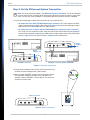
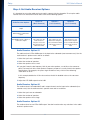
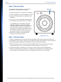
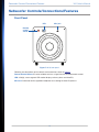
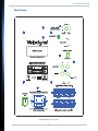
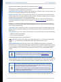
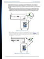
User’s Manual
Remote Controlled
Home Theater Subwoofers
Wi-Q10BV / Wi-Q10BVE
Wi-Q12BV / Wi-Q12BVE
Enjoy.
Thank you for choosing a Velodyne. Our passion for high performance, low-distortion bass is the driving force
behind our worldwide reputation in audio and technical innovation.
We are pleased to bring the Velodyne sound experience to your home!
2
Wi-Q User’s Manual
To reduce the risk of electric shock, do not remove cover (or back). No user-serviceable parts inside.
Refer servicing to qualified service personnel.
Caution
The lightning flash with arrowhead symbol is intended to alert the user to the presence of uninsulated
“dangerous voltage” within the product’s enclosure that may be of sufficient magnitude to constitute a
risk of electric shock to persons.
The exclamation point symbol is intended to alert the user to the presence of important operating and
maintenance (servicing) instructions in the literature accompanying the subwoofer.
1
2
3
4
5
Read Instructions: All safety and operating instructions should be read before the product is operated.
Retain Instructions: The safety and operating instructions should be retained for future reference.
Heed Warnings: All warnings on the product and in the operating instructions should be adhered to.
Follow Instructions: All operating and use instructions should be followed.
Water and Moisture: To reduce the risk of fire or electric shock, do not expose the product to rain or moisture. The product should not be used
near water — for example, near a bathtub, washbowl, kitchen sink, laundry tub, in a wet basement, near a swimming pool or the like. Do not
expose the product to dripping or splashing fluids, and do not place objects filed with liquids, such as vases, on the product.
6 Carts and Stands: The product should be used only with a cart or stand recommended by the manufacturer, or sold with the
product. When using a cart, use caution when moving the cart/product combination to avoid injury from tipping-over.
7 Wall or Ceiling Mounting: The product should be mounted to a wall or ceiling only as recommended by the manufacturer.
8 Ventilation: Do not block any ventilation openings. Install in accordance with the manufacturer's instructions.The product
should be situated so that its location or position does not interfere with its proper ventilation. For example, the product should
not be situated on a bed, sofa, rug, or similar surface that may block the ventilation openings; or placed in a built-in installation
such as a bookcase or cabinet that may impede the flow of air through the ventilation openings.
9 Heat: Do not install near any heat sources such as radiators, heat registers, stoves, or other apparatus (including amplifiers) that produce heat.
10 Power Sources: The product should be connected to a power supply only of the type described in the operating instructions or as marked on
the product.
11 Grounding or Polarization: Do not defeat the safety purpose of the polarized or grounding-type plug. A polarized plug has two blades with one
wider than the other. A grounding-type plug has two blades and a third grounding prong. The wide blade or the third prong are provided for your
safety. When the provided plug does not fit into your outlet, consult an electrician for replacement of the obsolete outlet.
Caution
To prevent electrical shock, match wide blade of plug to wide slot, fully inserted.
12 Power-Cord Protection: Power-supply cords should be routed so that they are not likely to be walked on or pinched by items placed upon or
against them, paying particular attention to cords at plugs, convenience receptacles, and the point at which they exit from the product.
13 Cleaning: Clean only with a dry cloth.
14 Nonuse Periods: The power cord of the product should be unplugged from the outlet when left unused for a long period of time.
15 Object and Liquid Entry: Care should be taken so that objects do not fall and liquids are not spilled onto the enclosure.
16 Damage Requiring Service: Refer all servicing to qualified service personnel. Servicing is required when the product has been damaged in any
way, such as:
• The power-supply cord or plug has been damaged.
• Objects have fallen or liquid has been spilled into the product.
• The product has been exposed to rain or moisture.
• The product does not appear to operate normally or exhibits a marked change in performance.
• The product has been dropped or damaged.
17 Lightning: For added protection for the product during a lightning storm or when it is left unattended and unused for long periods of time, unplug
it from the wall outlet.
18 Overloading: Do not overload wall outlets, extension cords or integral convenience receptacles as this can result in a risk of fire or electric shock.
19 Attachments: Only use attachments and accessories specified by the manufacturer.
20 Voltage: Insure that the product is only connected to the rated source voltage. Failure to do so will result in damage to the product and possible
injury to the user.
3
Wi-Q User’s Manual
21 Mains Plug/Appliance Coupler: The mains plug/appliance coupler is used as a disconnect device. Always keep this feature readily operable for
quick disconnect for safety.
22 Double-Instulated:This equipment is a Class II, or double-insulated electrical appliance. It has been designed in such a way that it does
not require a safety connection to electrical earth.
23 Flame Source: No naked flame source, such as lighted candles, should be placed on the product.
24 Battery: The battery (battery or batteries or battery pack) shall not be exposed to excessive heat such as resulting from exposure to sunshine,
fire, or the like.
Caution
Danger of explosion if battery is incorrectly replaced. Replace only with the same or
equivalent battery type.
4
Wi-Q User’s Manual
Table of Contents
Table of Contents . . . . . . . . . . . . . . . . . . . . . . . . . . . . . . . . . . . . . . . . . . . . . . 5
Congratulations . . . . . . . . . . . . . . . . . . . . . . . . . . . . . . . . . . . . . . . . . . . . . . . 7
Product Features . . . . . . . . . . . . . . . . . . . . . . . . . . . . . . . . . . . . . . . . . . . . . . . . . . . . . . . . . . . . . . 7
Setup . . . . . . . . . . . . . . . . . . . . . . . . . . . . . . . . . . . . . . . . . . . . . . . . . . . . . . . 8
Step 1: Unpack Box . . . . . . . . . . . . . . . . . . . . . . . . . . . . . . . . . . . . . . . . . . . . . . . . . . . . . . . . . . . . 8
Step 2: Set Up WiConnect System Transmitter . . . . . . . . . . . . . . . . . . . . . . . . . . . . . . . . . . . . . . 9
Step 3: Mount WiConnect System Transmitter to Wall (Optional) . . . . . . . . . . . . . . . . . . . . . . . . 10
Step 4: Set Audio Receiver Options . . . . . . . . . . . . . . . . . . . . . . . . . . . . . . . . . . . . . . . . . . . . . . 11
Audio Receiver Option #1 . . . . . . . . . . . . . . . . . . . . . . . . . . . . . . . . . . . . . . . . . . . . . . . . 11
Audio Receiver Option #2 . . . . . . . . . . . . . . . . . . . . . . . . . . . . . . . . . . . . . . . . . . . . . . . . 11
Audio Receiver Option #3 . . . . . . . . . . . . . . . . . . . . . . . . . . . . . . . . . . . . . . . . . . . . . . . . 11
Step 5: Place/Connect Subwoofer . . . . . . . . . . . . . . . . . . . . . . . . . . . . . . . . . . . . . . . . . . . . . . . 12
Subwoofer Placement . . . . . . . . . . . . . . . . . . . . . . . . . . . . . . . . . . . . . . . . . . . . . . . . . . . 12
Connect Subwoofer . . . . . . . . . . . . . . . . . . . . . . . . . . . . . . . . . . . . . . . . . . . . . . . . . . . . 12
Step 6: Run Auto-EQ . . . . . . . . . . . . . . . . . . . . . . . . . . . . . . . . . . . . . . . . . . . . . . . . . . . . . . . . . . 13
Step 7: Set the Phase . . . . . . . . . . . . . . . . . . . . . . . . . . . . . . . . . . . . . . . . . . . . . . . . . . . . . . . . . 13
Subwoofer Controls/Connections/Features . . . . . . . . . . . . . . . . . . . . . . . . . 14
Front Panel . . . . . . . . . . . . . . . . . . . . . . . . . . . . . . . . . . . . . . . . . . . . . . . . . . . . . . . . . . . . . . . . . . 14
Rear Panel . . . . . . . . . . . . . . . . . . . . . . . . . . . . . . . . . . . . . . . . . . . . . . . . . . . . . . . . . . . . . . . . . . 15
Low-pass Crossover - 40 to 135 Hz . . . . . . . . . . . . . . . . . . . . . . . . . . . . . . . . . . . . . . . . 17
Subwoofer Direct . . . . . . . . . . . . . . . . . . . . . . . . . . . . . . . . . . . . . . . . . . . . . . . . . . . . . . 17
Receiver/Processor Subwoofer Outputs . . . . . . . . . . . . . . . . . . . . . . . . . . . . . . . . . . . . 17
Alternate Connections . . . . . . . . . . . . . . . . . . . . . . . . . . . . . . . . . . . . . . . . . . . . . . . . . . . . . . . . . 17
Line-Level Connections . . . . . . . . . . . . . . . . . . . . . . . . . . . . . . . . . . . . . . . . . . . . . . . . . 17
Speaker-Level Connections . . . . . . . . . . . . . . . . . . . . . . . . . . . . . . . . . . . . . . . . . . . . . . 19
Remote Control . . . . . . . . . . . . . . . . . . . . . . . . . . . . . . . . . . . . . . . . . . . . . . 20
Restoring Defaults . . . . . . . . . . . . . . . . . . . . . . . . . . . . . . . . . . . . . . . . . . . . 22
Maintain . . . . . . . . . . . . . . . . . . . . . . . . . . . . . . . . . . . . . . . . . . . . . . . . . . . . 22
Check/Replace Fuse . . . . . . . . . . . . . . . . . . . . . . . . . . . . . . . . . . . . . . . . . . . . . . . . . . . . . . . . . . 22
Protect Subwoofer from Damage . . . . . . . . . . . . . . . . . . . . . . . . . . . . . . . . . . . . . . . . . . . . . . . . 23
Clean . . . . . . . . . . . . . . . . . . . . . . . . . . . . . . . . . . . . . . . . . . . . . . . . . . . . . . . . . . . . . . . . . . . . . . 23
Troubleshoot . . . . . . . . . . . . . . . . . . . . . . . . . . . . . . . . . . . . . . . . . . . . . . . . 24
Protection Circuitry . . . . . . . . . . . . . . . . . . . . . . . . . . . . . . . . . . . . . . . . . . . 25
Service . . . . . . . . . . . . . . . . . . . . . . . . . . . . . . . . . . . . . . . . . . . . . . . . . . . . . 25
Specifications . . . . . . . . . . . . . . . . . . . . . . . . . . . . . . . . . . . . . . . . . . . . . . . . 26
Regulatory Information . . . . . . . . . . . . . . . . . . . . . . . . . . . . . . . . . . . . . . . . . 27
Legal Notice . . . . . . . . . . . . . . . . . . . . . . . . . . . . . . . . . . . . . . . . . . . . . . . . . 28
For Your Records. . . . . . . . . . . . . . . . . . . . . . . . . . . . . . . . . . . . . . . . . . . . . . 28
5
Wi-Q User’s Manual
Intentionally
Blank
6
Congratulations
Congratulations on your purchase of a Velodyne Wi-Q subwoofer. This system represents the state-of-the-art in
low frequency reproduction.
Product Features
• DSP-controlled
• Integral 2.4 GHz wireless receiver
• 10" long-throw woofer (Wi-Q10BV/Wi-Q10BVE)
• 12" long-throw woofer (Wi-Q12BV/Wi-Q12BVE)
• Built-in Class D power amplifier
• Downward-firing port design
• Front-mounted, 7-segment LED display
• One-touch, 5-band graphic equalizer with microphone included
• 4 selectable presets for customized listening mode
• Night-mode setting
• Mute control
• Adjustable (40 to 135 Hz) low-pass crossover with Subwoofer Direct setting
• Speaker-level inputs
• Line-level inputs
• Switchable standby mode that activates when signal is absent
• Variable volume control with digital LED readout
• Selectable phase control (0, 90, 180, or 270 degrees)
• Dual staggered low-pass crossover; 12 db/octave initial, 24 db/octave ultimate
• Anti-clipping circuit
• Over- excursion protection
7
Wi-Q User’s Manual
Setup
Your Wi-Q subwoofer is easy to set up. Once you finish setting up, use the remote control to operate the subwoofer.
Below is an overview of the setup steps. The rest of this section provides details on these steps.
Step 1: Unpack the box.
Step 2: Set up the WiConnect System Transmitter.
Step 3: Mount the WiConnect System Transmitter to the wall (optional).
Step 4: Set the audio receiver options.
Step 5: Place and connect the subwoofer.
Step 6: Run the automatic equalizer.
Step 7: Set the phase.
Step 1: Unpack Box
1. Unpack the system using caution when lifting and moving to avoid injury.
2. Save the carton and packing materials for future use.
Note: Use this packaging if you ever need to move or ship the subwoofer to Velodyne for service.
Using other packaging may result in severe damage. To save storage space, flatten the box and
place the other packing material in a plastic bag.
3. Record the serial number in the space provided on page 28.
4. Make sure you have all the items shown in Figure 1. If any items are missing or damaged, contact the
retailer where you purchased this subwoofer.
Self-tapping
wood screws
MIC
Transmitter
EQ
Power cord
Mute
PWR
Presets
Power adaptor
1
2
+
Movies
Rock
Volume
3
4
-
Jazz
Games
Light
0
Night
270
Phase
90
180
Subwoofer
Microphone
Mic stand
Remote
control
Figure 1: Wi-Q package contents
5. Make sure you also have an RCA-to-RCA (male-male) cable, so you can
connect the transmitter to your audio system.
Figure 2: RCA-to-RCA
8
Setup
Wi-Q User’s Manual
Step 2: Set Up WiConnect System Transmitter
Note: The Wi-Q transmitter model is the WiConnect System Transmitter. The Wi-Q subwoofer
must be within 50 feet (15 meters) of the transmitter to be able to receive the wireless signal. Also,
make sure that the same CHANNEL is selected on both the transmitter and the subwoofer.
1. Do one of the following to connect the transmitter to your audio receiver.
• For Audio Receivers with LFE/SUB Output (most common): This setup requires one RCA
cable. Plug one end of the RCA cable into the LFE input on the transmitter and plug the other
end into the LFE or SUB output on your audio receiver.
• For Audio Receivers or Zones without LFE/SUB Output or Connection (less common):
This setup uses one stereo RCA cable. Plug one channel of the RCA cable into the R input on
the transmitter and the R output on your audio receiver. Plug the other channel of the RCA cable
into the L input on the transmitter and the L output on your audio receiver.
Front
L
LFE
L
Front
R
Center
R
Surround
+
12v
Trigger
-
-
L
+
R
LFE
TX
INPUT
1234
CHANNEL
DC IN
-
+
Power
adaptor jack
Front
L
LFE
L
R
L
Front
R
Center
12v
Trigger
LFE
TX
INPUT
-
-
+
Left/Right connection (without LFE/SUB)
Figure 3: Transmitter connections
2. Plug the power adapter into the back of the transmitter. Plug
the other end of the adapter into a power outlet.
3. Make sure the CHANNEL setting on the transmitter matches
the CHANNEL setting on the back of the subwoofer. For
example, choose CHANNEL 2 in both places. You have four
channels to choose from.
Channel selector
LFE
-
+
LFE/SUB connection
R
+
1234
CHANNEL
DC IN
L
R
Surround
TX
INPUT
1234
CHANNEL
DC IN
-
+
Figure 4: Channel selections
9
Power
adaptor
jack
Setup
Wi-Q User’s Manual
Step 3: Mount WiConnect System Transmitter to Wall
(Optional)
You can mount the transmitter on the wall or place it with your other audio components. The transmitter
can be mounted in a vertical or horizontal orientation, and the Wi-Q system doesn’t need to be visible to
function properly.
1. Use the template below to mark the mounting locations on the wall.
2. Mark the two screw locations for either the horizontal or vertical mounting orientation.
3. Hand turn each of the included self-tapping wood screws into each marked location. Tighten the
screws until about 1/8” (3.17mm) of the screw shank is exposed.
Note: The provided wood screws aren’t suitable for stone or other hard wall surfaces. If you can’t
hand drive the screws, you may need to drill holes and provide other wall anchors.
4. Hook two of the slotted holes on back of the transmitter onto the two screws.
Figure 5: Transmitter mounting template
10
Setup
Wi-Q User’s Manual
Step 4: Set Audio Receiver Options
It is important to set up the audio receiver to work in concert with the subwoofer. To set up the audio
receiver refer to its instruction manual and use one of the following options:
Option #1
(Most Common)
Option# 2
(Less Common)
Option# 3
(Less Common)
Audio receiver has LFE or SUB
output
Yes
Yes
No
Use audio receiver’s LFE or
SUB output as subwoofer’s
input
Yes
No
No
Use audio receiver’s full
bandwidth R and L outputs as
subwoofer’s inputs
No.
This setup uses the
audio receiver’s
low-pass crossover
filter instead of your
subwoofer’s filter.
Yes.
This setup uses your
subwoofer’s low-pass
crossover filter instead
of the audio receiver’s
filter.
Yes.
This setup uses your
subwoofer’s low-pass
crossover filter instead
of the audio receiver’s
filter.
Audio Receiver Options
Audio Receiver Option #1
The audio receiver’s LFE or SUB output is the input to the subwoofer (most common case). Use the
audio receiver’s speaker menu and set as follows:
1. Select that you have a subwoofer.
2. Select the number of speakers.
3. Select the speaker size as small.
4. If you don’t know the low frequency limit of your main speakers, use 80 Hz as the crossover
point. The lower limit of the main speaker’s frequency response is usually listed in the speaker
specifications. For example, the specs might include an entry similar to the following:
“3 dB down at 45 Hz.”
In this example, double the 45 Hz value and use the 90 Hz doubled-value as the crossover
frequency.
5. Adjust the LFE /SUB output level to 0 dB.
Audio Receiver Option #2
The audio receiver’s full bandwidth R and L output channels are the input to the subwoofer (less
common case). Use the audio receiver’s speaker menu and set as follows:
1. Select that you have no subwoofer.
2. Select the number of speakers.
3. Select the speaker size as large.
Audio Receiver Option #3
The audio receiver has no LFE or SUB output. You don’t need to make any selections in the audio
receiver’s speaker menu.
11
Setup
Wi-Q User’s Manual
Step 5: Place/Connect Subwoofer
Subwoofer Placement
True subwoofers operate at extremely low frequencies which are primarily omni-directional.
Depending on the acoustic properties of the listening room, placement can drastically influence your
subwoofer’s frequency response and output levels.
Use the following guidelines to find the optimal location for your subwoofer:
• For highest output, place the subwoofer within one foot of a corner; this location offers the
greatest output levels.
• For smoother response, but less output, place your subwoofer along a wall.
• The worst location for a subwoofer is away from any walls, close to the center of a room, or
close to a doorway or opening to another room. Avoid these locations when possible.
• When using a pair of Velodyne subwoofers in stereo, feed each subwoofer with one channel
and place each subwoofer near the satellite of the same channel. You can also place one
mid-way along a wall and the other in a corner for a very smooth, deep response.
• Depending on the size and type of furnishings in the room, you may not be able to achieve
perfect placement. We suggest that you experiment with the location during setup to find what
sounds best when seated in your typical listening position.
• For more information on placement, see Velodyne’s Subwoofer Placement Recommendations
Guide (http://velodyne.com/support/faq#sub).
• Regardless of where you install your Velodyne subwoofer, it must remain in an upright position
(woofer facing forward). Do not use, ship, or store the subwoofer in any other position for an
extended period of time; this may damage the unit and this type of damage is not covered
by the warranty.
• The subwoofer is NOT magnetically shielded. If you use it with an older CRT monitor or TV,
keep it at least two feet from the monitor. Experiment for correct minimum distance by
minimizing distortion of the picture and colors.
Caution
Warning
This subwoofer has electronics built into the cabinet. Do not place the cabinet next to
sources of heat such as direct sunlight, furnace registers, radiators, etc. Do not place
the unit near sources of excessive moisture such as high humidity environments,
evaporative coolers, humidifiers, etc. The power cord should be routed in such a way
that it will not be walked on, pinched or compressed in any way that could result in
damage to the insulation or wire.
To prevent fire or shock hazard, do not expose this product to rain or moisture. To avoid
electrical shock, do not open the speaker enclosure or amp chassis cover. Please
observe all warnings on the equipment itself. There are no user serviceable parts inside.
Refer all service questions to your authorized Velodyne dealer.
Connect Subwoofer
1. Determine optimal placement as described in the previous section.
2. Connect the female end of the power cable to the back of the subwoofer and the male end to a
power outlet.
3. Press the POWER button on the back of the subwoofer, so that it is in the ON position.
12
Setup
Wi-Q User’s Manual
Step 6: Run Auto-EQ
The automatic equalizer adjusts the subwoofer’s
sound to best suit its position in the room.
Mic jack
1. Remove the grille from the front of the subwoofer.
MIC
2. Insert the supplied mic into the supplied mic stand.
3. Plug the mic into the Mic jack on the front of the
subwoofer.
4. Place the mic in your preferred listening position.
5. On the remote, press EQ for about 2-3 seconds.
The subwoofer emits sweep tones that span
frequencies between 20 and 150 Hz. While
making the frequency sweeps, the LED displays
“AU” and the system adjusts fixed-frequency
graphic EQ filters for the flattest response at the
mic. When the sweeps are done, the unit saves
the settings and returns to normal operation.
6. To prevent accidentally activating Auto-EQ,
remove the mic from the Mic jack.
Figure 6: Mic jack
Step 7: Set the Phase
The Phase setting optimizes the transition from the subwoofer to the satellite speakers based on your
listening position. You can adjust the phase of the subwoofer’s output signal to correct any mismatch and
the resulting cancellation between the subwoofer and your main speakers/amplifier.
1. While listening to music, press each of the four PHASE buttons on the remote control. The phase
setting shows on the LED as “PH” followed by the phase number: 0, 90, 180 or 270.
2. Listen to the mid-bass transition for a few moments, and then press the next PHASE button.
3. Select the PHASE button that provides the smoothest transition between the subwoofer and the
satellite speakers, without peaks or dips. If the settings sound similar, use the “0” position.
13
Subwoofer Controls/Connections/Features
Wi-Q User’s Manual
Subwoofer Controls/Connections/Features
Front Panel
LED
Mic jack
Remote
control
sensor
MIC
Figure 7: Wi-Q front panel
Following are descriptions of the controls and connections shown in Figure 7.
Remote Control Sensor: IR sensor window receives a signal from the included remote control.
LED: 2.5 digit, seven segment LED readout displays volume, phase and Auto-EQ.
Mic Jack: Connector for the supplied microphone to use during the Auto-EQ process.
14
Wi-Q User’s Manual
Rear Panel
Figure 8: Wi-Q Rear Panel
15
Subwoofer Controls/Connections/Features
Wi-Q User’s Manual
Following are descriptions of the controls and connections shown in Figure 8.
Power: Turns the subwoofer on/off. Even if you are using the Auto on/off feature, this switch must be in
the ON position for the subwoofer to receive power.
Power Connector/Fuse Drawer: Connects the subwoofer to a wall outlet so that it can receive power. The
fuse drawer is located at the bottom of the power connector.
Speaker Level Input: If you’re not using the transmitter, you can connect these input terminals to the
speaker output terminals on your amplifier or receiver. For this connection method, go to your receiver’s
Speaker Setup menu and select the Large speaker option.
Speaker Level Output: If you’re using speaker-level inputs, you can use these terminals to send a
crossed-over speaker-level signal to the front speakers. See Low-Pass Crossover: for details on this
crossover.
IR Input: This connection supports third-party infrared remote sensors, such as Elan or Xantech, for
placement closer to your other remote controlled equipment. Use this feature to avoid awkward angles
when using the remote control.
Line Output: If you’re using line-level inputs, you can connect these jacks to the LINE IN input on your
preamp. With this connection method, you use the Wi-Q’s internal high-pass crossover, which rolls off
below 80 Hz.
Line Input/LFE: If you’re not using the transmitter, you can connect these jacks to one of the following:
• LINE OUT output on your preamp
• LFE on your receiver/processor
• Subwoofer output on your receiver/processor
Note: When using the LFE output, plug a single cable into the L – LFE input, or for more signal,
use a “Y” connector (not included) and feed the signal into both R and L inputs.
Stand By Mode/Always On: When this switch is in the STANDBY MODE position, the subwoofer
automatically turns itself on when an audio signal is present. If there’s no signal for about thirteen minutes,
the unit switches to standby mode (blank LED), which draws minimal power. The default setting for this
switch is ALWAYS ON. To activate the Auto on/off feature, slide this switch to the STANDBY MODE
position.
Warning
If the signal level from your receiver’s Sub-out channel is weak, the subwoofer shuts off while
you are listening to it. To correct this issue, see the next section, Volume Up/Down:.
Volume Up/Down: Use these controls to achieve balanced volume levels between your main speakers
and the subwoofer. When you press Volume Up/Down, the LED displays the current volume setting. You
can also adjust subwoofer volume with the remote control. The default volume setting is 30 out of 80.
Warning
Some receivers are preset with the Sub-out channel set at a minimum level. If your receiver
Sub-out channel is too low, the subwoofer may have weak output, sound noisy or distorted,
and the Auto on/off feature may not operate properly.
To avoid these issues, make sure that your receiver’s Sub-out channel is set to the same
output level as your front right and left channels. Refer to your receiver’s manual for details
on adjusting the individual channel levels.
Channel: This control sets the channel used for wireless communication between the subwoofer and the
transmitter. Make sure that the channel selection is the same on both the subwoofer and transmitter.
16
Subwoofer Controls/Connections/Features
Wi-Q User’s Manual
Low-Pass Crossover: Use this knob to select the frequency above which you wish to cut off the signal to
the subwoofer. When the knob is turned all the way to the left, the Subwoofer Direct feature is invoked and
the subwoofer plays all frequencies up to 135 Hz.
Low-pass Crossover - 40 to 135 Hz
The crossover control allows you to adjust the upper limit of the subwoofer’s frequency response
from 40 to 135 Hz. The subwoofer’s response begins rolling off above the frequency at which you
set this control. Set the crossover frequency to obtain a smooth and seamless transition from the
subwoofer to the main speakers in your system. The default crossover setting is 80 Hz. If your main
speakers are small with limited low frequency output, choose a higher frequency (such as 100 - 120
Hz). For larger speakers which have greater low frequency output, choose a lower number (such as
70 Hz).
Note: The subwoofer sums the left and right channels and passes the combined signal through
an adjustable low-pass crossover before sending it to the amplifier.
Subwoofer Direct
Use this setting on the low-pass crossover knob to allow frequencies up to 135 Hz into the
subwoofer. See the next section, Receiver/Processor Subwoofer Outputs for more about this feature.
Receiver/Processor Subwoofer Outputs
Your Velodyne subwoofer is designed to operate using the full-range audio signal for input when
using our built-in crossover. Many home theater processors/receivers (Dolby Digital™, DTS™,
THX™) have a “subwoofer out” jack (sometimes labeled “LFE”) that is internally filtered, settable at
the receiver/processor, and designed to be used with a powered subwoofer. In some installations, it
is beneficial to use BOTH the Velodyne crossover and the receiver/processor crossover, to achieve
a steeper crossover slope. In rare cases, combining an external crossover with the subwoofer’s
internal crossover may result in low output and increased noise. In these installations you may need
to bypass the crossover in either the processor or subwoofer, or simply set one crossover to a higher
frequency (such as 120 Hz) to restore maximum performance.
Alternate Connections
Your Wi-Q subwoofer uses modern 2.4 GHz wireless technology, so in most cases you can establish the
audio connection simply by connecting the transmitter to your audio receiver. In some situations, however,
you may need to connect RCA or speaker cables to your audio receiver. For these situations, your
subwoofer includes both line-level (RCA-type) and high-level (5-way binding post-type) connectors.
Note: Do not use both the RCA/Phono INPUT and SPEAKER LEVEL INPUT connections
simultaneously.
Line-Level Connections
Use the line-level jacks to connect your subwoofer to a pre-amp, a signal processor (with LFE out or
Sub-out), a line-level crossover, or a receiver with pre-amp level outputs. With line-level connections,
always use shielded phono cables, and to avoid potential noise problems, use the shortest cables
possible.
17
Subwoofer Controls/Connections/Features
Wi-Q User’s Manual
When using the line-level jacks, some receivers may not provide enough signal for the unit’s
Auto-On/Off feature to operate properly. Additionally, this lack of signal may also cause the
subwoofer to produce less output than it is capable of. To alleviate this condition, we recommend the
following:
• When using a receiver with LFE out, be sure the LFE channel sends an adequate signal to the
subwoofer. The subwoofer’s default volume setting is 30 out of 80. See your receiver’s manual
to adjust the LFE channel on your receiver or processor to achieve the desired bass output.
Front
L
LFE
L
Front
Center
R
R
Surround
+
12v
Trigger
-
-
+
Figure 9: LFE Subwoofer Connection
• When using line-level jacks, use both the Left and Right inputs as shown in Figure 10—never
use just the Left or Right input. If using line-level connections from a preamp or signal processor,
use both Left and Right inputs from your preprocessor or preamp and connect them to the Left
and Right inputs on your subwoofer.
Front
L
LFE
L
Front
12v
Trigger
R
Center
R
Surround
+
-
-
+
Figure 10: Line-Level Subwoofer Connection
18
Subwoofer Controls/Connections/Features
Wi-Q User’s Manual
Speaker-Level Connections
Use the speaker-level jacks to connect the subwoofer directly to the speaker outputs of an integrated
amplifier or receiver. Your amplifier bears no additional load when you use these high-impedance
inputs.
With speaker-level connections, use a high-quality speaker cable that mates well with the
connectors. Be very careful to avoid any loose strands or frayed wires that may result in a short and
damage your equipment. Cables of extremely large size are not required due to the low current draw
of this type of connection. Extremely large gauge wire may not properly fit in the terminals and may
result in a poor connection or short circuit.
Front
L
LFE
L
Front
12v
Trigger
R
Center
R
Surround
+
-
-
+
Figure 11: High-Level Subwoofer Connection
19
Remote Control
Wi-Q User’s Manual
Remote Control
This section describes how to use your Wi-Q subwoofer remote control.
Power: Puts your subwoofer in reduced-power mode, which stops play
and turns off the display. Press this button again to return to full operation.
This function is subordinate to the standby mode on the rear panel, and
you must restart the subwoofer if that feature has triggered. To fully turn off
the subwoofer, press the POWER switch on the back of the subwoofer.
Mute: Silences the subwoofer’s output and the LED on the sub shows 00.
To unmute the subwoofer, press the MUTE button again and the original
volume setting shows on the LED.
EQ
Mute
PWR
Presets
1
2
+
EQ: Runs the automatic equalizer, so your Wi-Q subwoofer sounds best
for its position in the room. See Step 6: Run Auto-EQ for details on using
this feature.
Movies
Rock
Volume
3
4
-
Phase: Optimizes the subwoofer’s bass performance relative to the
speakers and your listening position. This control changes the phase of the
subwoofer’s output signal to correct mismatches and resulting
cancellation between the subwoofer and your main speakers/amplifier.
The phase setting shows on the LED as “PH” followed by the phase
number: 0, 90, 180 or 270. See Step 7: Set the Phase for details on using
this feature.
Jazz
Games
Light
0
Night
270
Phase
90
Light: Turns the numeric LED on your subwoofer off. To reactivate the LED,
press the LIGHT button again. When the LED is off, it lights only when you
make adjustments to the subwoofer controls and then turns off again.
Night: Limits the maximum dynamic output of the subwoofer for late night
listening or considering close neighbors at any time. Press the NIGHT
button to turn night mode on/off. When you activate night mode, the LED
briefly displays “n.” When you deactivate night mode, the LED shows “n
off” and then returns to normal function.
180
Figure 12: Wi-Q Remote
Volume Control: Balances the output from the subwoofer to the main
speakers in your system. Use this control to achieve similar volume levels
from both the main speakers and subwoofer. When pressing volume up or down, the LED displays the volume level.
Note:
The remote control included with your specific subwoofer may not look the same as the remote
control shown in the illustration, but the functions and performance are identical to those described here.
Warning
Some receivers are preset with the Sub-out channel set at a minimum level. If your receiver Sub-out
channel is too low, the subwoofer may have weak output, sound noisy or distorted, and the Auto on/off
feature may not operate properly.
To avoid these issues, make sure that your receiver’s Sub-out channel is set to the same output level as
your front right and left channels. Refer to your receiver’s manual for details on adjusting the individual
channel levels.
Note:
You can also adjust the subwoofer’s volume with the Volume buttons on the back of the
subwoofer. These buttons have the same effect as pressing the up and down volume buttons on your
remote. The default volume setting is 30 out of 80.
20
Wi-Q User’s Manual
Presets: Switches between four preset bass modes that offer the following characteristics:
• Movies: Maximum output and impact for explosions and other action adventure movie content.
• R&B/Rock: Driving bass found in today’s rock music.
• Jazz/Classical: The tightest, cleanest, lowest distortion bass. The flattest frequency response of the four
presets.
• Games: Maximum loudness available for video games impact.
Note:
The presets simply provide different sound characteristics. You can use any of the presets for any
type of listening based on your sonic preference.
The following table lists the preset characteristics and musical style recommendations for each preset.
Preset
Subsonic
Filter
Frequency
EQ
Frequency
EQ Level
Volume
Differential
Musical Style
Recommendations
Movies
25 Hz
37 Hz
+3 db
+5 db
Action Adventure Movies
R&B - Rock
28 Hz
50 Hz
+3 db
+1 db
Country – Rock
Indie Music
Pop
Rock
Classic Rock
Dance and DJ
Hard Rock/Heavy Metal
Latin Music
R&B
Rap and Hip-Hop
Soundtracks
Jazz Classical
(Reference)
15 Hz
N/A
N/A
N/A
Country – Soft
Folk
Alternative Rock
Blues
Broadway and Vocalists
Children’s Music
Christian and Gospel
Classical
Miscellaneous
Movies – Non-Action Adventure
New Age
Opera and Vocal
Soundtracks
Games
34 Hz
60 Hz
+3 db
+4 db
Video Games
21
Restoring Defaults
Wi-Q User’s Manual
Restoring Defaults
You can restore the factory default settings for your Wi-Q subwoofer by pressing PRESET buttons on the remote
in EXACTLY the following order:
• Preset 1: Movies
• Preset 2: R&B – Rock
• Preset 3: Jazz – Classical
• Preset 4: Games
• Preset 4: Games
• Preset 3: Jazz – Classical
• Preset 2: R&B – Rock
• Preset 1: Movies
When you press the presets in the above order, the front LED displays “P3” to indicate that you restored the factory
defaults—including resetting the volume level to 30 out of 80.
Maintain
Check/Replace Fuse
Your Velodyne Wi-Q subwoofer works in regions using 120V or 230V mains voltage. The unit switches itself
for use with either voltage level.
To replace the fuse, follow these steps:
1. On the back of the subwoofer, locate the fuse drawer slot
at the base of the power cord connector.
2. Insert a flat-blade screwdriver in the fuse drawer slot and
tilt the handle towards the subwoofer to open the fuse
drawer. (Do not attempt to detach the drawer from the
subwoofer.) The drawer contains two fuses - an active fuse
and a replacement fuse.
Fuse
drawer
Slot
Figure 13: Fuse drawer slot
3. Carefully remove the active fuse. Hold it up to a light
source and see if the conductor in the glass tube is still
continuous from end to end. You can also compare it
to the replacement fuse. If the active fuse looks in any
way bad, move the replacement fuse into the active
cavity. There is no fuse polarity, so it doesn’t matter
which way it is inserted.
4. Push the fuse drawer into the back of the subwoofer
until it clicks into place.
Storage cavity
Active cavity
Figure 14: Fuse drawer cavities
Note:
If a fuse burns out or becomes damaged, you must replace the fuse with the same size and value
of fuse.
22
Wi-Q User’s Manual
Protect Subwoofer from Damage
DO NOT PUT HEAVY OBJECTS ON TOP of the subwoofer cabinet or transmitter that could scratch or dent
the cabinet or case.
DO NOT ALLOW OBJECTS TO FALL INTO OR LIQUIDS TO SPILL ON THE SUBWOOFER ENCLOSURE
OR TRANSMITTER CASE. DO NOT EXPOSE SUBWOOFER OR TRANSMITTER TO DRIPPING OR
SPLASHING FROM LIQUIDS.
DO NOT PLACE LIQUID-FILLED OBJECTS ON OR NEAR THE SUBWOOFER OR TRANSMITTER.
Examples of liquid-filled objects include flower vases, beverages and liquid-fueled lamps.
DO NOT PUSH OBJECTS OF ANY KIND into the subwoofer or transmitter.
DO NOT PLACE BURNING CANDLES, INCENSE, OR SMOKING PRODUCTS ON TOP OF OR NEAR THE
SUBWOOFER OR TRANSMITTER.
DO NOT PLACE A LAPTOP COMPUTER ON TOP OF THE SUBWOOFER OR TRANSMITTER. Damage
could occur to either the laptop hardware or the subwoofer finish.
Clean
USE A CLEAN, SOFT DRY CLOTH to remove dust or fingerprints from the subwoofer cabinet. Unplug the
subwoofer power cord from the power outlet before cleaning to prevent static electricity from damaging the
subwoofer during cleaning.
DO NOT CLEAN THE SUBWOOFER CABINET OR TRANSMITTER CASE with detergents, soaps,
abrasives, aerosol sprays, chemical solvents, alcohol, or other cleaning solutions.
23
Wi-Q User’s Manual
Troubleshoot
Subwoofer’s blue display light (on front panel) doesn’t light up
1. Verify that the subwoofer is plugged into a live power outlet.
2. Verify that the subwoofer power switch (on the back of the subwoofer) is in the ON position.
3. Verify that the power cord is not damaged. If damaged, replace the cord.
4. Press the LIGHT button on the remote to verify that the subwoofer isn't in LED-off mode.
Subwoofer isn’t producing sound and blue display light (on front panel) is on
1. Verify that the transmitter is plugged into a live power outlet.
2. Verify that the transmitter’s inputs are connected to the audio receiver’s output. This wire may have become
accidentally disconnected.
3. Increase the subwoofer’s VOLUME level.
4. Increase the receiver’s LFE or SUB OUT volume level, if it’s adjustable.
5. If your receiver has a switch or menu to enable its LFE or SUB OUT, make sure this switch or menu is set to
ON or YES.
6. Verify that the transmitter’s light is on solid. If the transmitter’s light isn’t on solid and the same
CHANNEL is selected on both the transmitter and receiver, select another matching CHANNEL
for the transmitter and receiver.
7. Verify that your audio receiver or processor is in a bass management surround mode/input, and that the LFE
or SUB terminals are producing output. Typically "Direct" surround connections/modes bypass this and there
will be no output at these terminals.
8. Verify that the subwoofer is not in mute mode by pressing the MUTE button on the remote control.
Bass doesn’t sound loud enough
1. Increase the subwoofer’s VOLUME level.
2. Increase the receiver’s LFE or SUB OUT volume level, if it’s adjustable.
3. Put the subwoofer closer to a corner of your room.
Subwoofer output is distorted, intermittent or stops:
• The subwoofer may have shut down due to the protection circuitry.
1. Reduce the volume setting; or
2. Shut the subwoofer off until normal operating conditions return.
• The transmitter and audio receiver may have lost their broadcast connection.
1. Turn off power to the subwoofer, transmitter, and audio receiver.
2. Turn power back on to the transmitter, then the audio receiver, and then the subwoofer.
3. If cycling the power doesn’t re-establish the broadcast connection, select another matching CHANNEL
for the transmitter and subwoofer.
4. If selecting another CHANNEL doesn’t re-establish the broadcast connection, decrease the distance
between the subwoofer and the transmitter to increase the broadcast signal strength between them.
5. Verify that the transmitter and subwoofer aren’t in close proximity to other electronic devices
that could interfere with wireless transmission and reception. Turn all devices off except for the Wi-Q
transmitter, the audio receiver, and the subwoofer. Next, turn each of the other devices on/off until you
find the interfering device, and then increase the distance between the interfering device and the audio
system.
24
Wi-Q User’s Manual
Protection Circuitry
The subwoofer is equipped with protection circuitry to provide maximum performance and reliability. The
subwoofer is protected against:
• Overdriving the speaker
• Overdriving the amplifier
• Overheating the amplifier
• Excessive drop in power line voltage
If the protection circuitry is active, the unit may cycle on and off until operating parameters return to normal. Under
more serious conditions, the unit may shut off completely. Normal operation should return upon cooling, but you
may need to turn the power off and then on again to reset the unit.
The overdrive protection circuitry operates constantly without being audible under most situations.
If the subwoofer shuts down, reduce the volume setting and turn the subwoofer off until it cools down. The time
the subwoofer takes to cool down depends on the ambient room temperature, but typically it takes at least 10
minutes for the subwoofer to cool down and recover from a thermal shutdown.
Also, plug the unit into a different wall socket. Overloaded sockets or damaged home wiring circuits can cause
power voltage drops while the subwoofer is drawing high power levels. This condition can result in the subwoofer
shutting down intermittently.
Service
DO NOT ATTEMPT TO SERVICE THE SUBWOOFER OR TRANSMITTER YOURSELF beyond what is described in
this owner’s manual.
ONLY USE QUALIFIED SERVICE TECHNICIANS TO REPAIR DAMAGED PARTS. Service the subwoofer or
transmitter using qualified service technicians when:
• A power cord or plug is damaged
• The power socket on the subwoofer or transmitter is damaged
• Objects have fallen or liquid has spilled into the subwoofer or transmitter
• The subwoofer or transmitter was rained on or has become partially or fully submerged in water
• The subwoofer does not operate normally or exhibits a marked change in performance
• The cabinet has been dropped or is damaged
• The subwoofer driver’s cone and/or suspension is physically damaged
25
Wi-Q User’s Manual
Specifications
Model
Wi-Q10BV/Wi-Q10BVE
Wi-Q12BV/Wi-Q12BVE
Woofer
10” (24.5 cm) forward firing
(8.2” piston diameter)
12” (30.5 cm) forward firing
(9.7” piston diameter)
Amplifier
Class D
Class D
Cabinet Design
Extended Excursion
Down-firing port
Extended Excursion
Down-firing port
Frequency Response
Overall
+/-3dB
16 - 240 Hz
28 - 120 Hz
14.6 - 240 Hz
25 - 120 Hz
Voice Coil
2” 2-layer copper
2” 2-layer copper
Cone
Reinforced fiber
Reinforced fiber
Magnet Structure Weight
5.36 lb
7.40 lb
High-Pass Crossover
80 Hz*, 6 db/octave
80 Hz*, 6 db/octave
Low-Pass Crossover
40 - 135 Hz adjustable
(12 dB/octave, 24 dB ultimate)
40 - 135 Hz adjustable
(12 dB/octave, 24 dB ultimate)
Outputs
Gold plated line-level
Nickel plated speaker level
Gold plated line-level
Nickel plated speaker level
Inputs
Gold plated line-level
Nickel plated speaker level
Gold plated line-level
Nickel plated speaker level
Digital Phase
0, 90, 180, 270 degrees
0, 90, 180, 270 degrees
Auto On/Off
Yes
Yes
Removable Grill
Yes
Yes
LED Display
Yes
Yes
Transmitter Frequency
2.4 GHz
2.4 GHz
Transmitter Range
50’ (15 m)
50’ (15 m)
Accessories
Mic, mic stand, remote control,
transmitter, power supply, and
batteries
Mic, mic stand, remote control,
transmitter, power supply, and
batteries
Cabinet (H,W,D)
(includes feet and grille)
17.31” x 15.25” x 17”
(44 x 38.7 x 43.2 cm)
18.44” x 16.375” x 18”
(46.8 x 41.6 x 45.7 cm)
Shipping Weight (approx.)
40 lb (18.2 kg)
45 lb (20.5 kg)
Note:
Varying speaker and amplifier input load impedances may cause the high-pass crossover
frequency to slightly vary. The transmitter range stated above is under ideal conditions. Specifications are
subject to change without notice.
26
Wi-Q User’s Manual
Regulatory Information
FCC Compliance Statement
1. This device complies with Part 15 of the FCC Rules. Operation is subject to the following two conditions:
• This device may not cause harmful interference.
• This device must accept any interference received, including interference that may cause undesired operation.
2. Changes or modifications not expressly approved by the party responsible for compliance could void the user's authority to operate
the equipment.
3. This equipment has been tested and found to comply with the limits for a Class B digital device, pursuant to Part 15 of the FCC Rules.
These limits are designed to provide reasonable protection against harmful interference in a residential installation.
NOTE: This equipment generates, uses, and can radiate radio frequency energy and, if not installed and used in accordance with the
instructions, may cause harmful interference to radio communications. However, there is no guarantee that interference will not occur in a
particular installation. If this equipment does cause harmful interference to radio or television reception, which can be determined by turning
the equipment off and on, the user is encouraged to try to correct the interference by one or more of the following measures:
• Reorient or relocate the receiving antenna.
• Increase the separation between the equipment and receiver.
• Connect the equipment into an outlet on a circuit different from that to which the receiver is connected.
• Consult the dealer or an experienced radio/TV technician for help.
FCC Radiation Exposure Statement
This equipment complies with FCC radiation exposure limits set forth for an uncontrolled environment. This equipment should be installed
and operated with minimum distance 20cm between the radiator & your body.
IC warning
English:
This device complies with Industry Canada licence-exempt RSS standard(s). Operation is subject to the following two conditions:
1. This device may not cause interference, and
2. This device must accept any interference, including interference that may cause undesired operation of the device.
Changes or modifications not expressly approved by the party responsible for compliance could void the user's authority to operate
the equipment.
French:
Le présent appareil est conforme aux CNR d'Industrie Canada applicables aux appareils radio exempts de licence. L'exploitation
est autorisée aux deux conditions suivantes :
1. L'appareil ne doit pas produire de brouillage, et
2. L'utilisateur de l'appareil doit accepter tout brouillage radioélectrique subi, même si le brouillage est susceptible d'en
compromettre le fonctionnement.
European Union (EU) Declaration of Conformity
This product complies with the requirements and other relevant provisions of the R&TTE Directive as well as CE-LVD (Safety) and CE-EMC
(Emissions & Immunity).
Radio Frequency Exposure Limit Requirements
Keep a minimum separation of 8 inches (20 cm) between the transmitter and any person to comply with FCC and EU exposure limit
requirements.
Listen Responsibly
REFRAIN FROM LISTENING TO MUSIC AT HIGH VOLUMES for long periods of time to protect you from permanent hearing
damage. The United States’ Occupational Health and Safety Administration (OSHA) standards recommend not listening to sound
levels of 85 dB for more than 8 hours and to wear hearing protection if sound levels exceed 85 dB. Refer to the OSHA website
for more information and updated recommendations about sound levels and hearing damage:
www.osha.gov/dts/osta/otm/noise/standards_more.html
27
Wi-Q User’s Manual
Legal Notice
Subwoofer Recycling
These products should not be treated as household waste. Instead, the subwoofer and transmitter should be taken to a
certified collection point so that the electrical and electronic components can be recycled. By recycling these products
through a certified collection point, you prevent potential environmental damage and help to conserve natural resources used
in these products. Certain international, national and/or local laws and/or regulations may also apply regarding the disposal
of this subwoofer. For further information, contact your local waste disposal service, your local city government office, or the
retailer where you purchased this subwoofer.
Trademarks
The Velodyne logo is a trademark of Velodyne Acoustics, Inc. All other trademarks are the property of their respective owners.
For Your Records. . .
Date
Purchased
Dealer
Serial #
Note: If you need to file a warranty claim for your product, you still need to submit either of the
following to Velodyne:
• Original sales invoice
• Other proof of ownership and date of purchase
Please validate your product warranty by completing the online registration within 30 days:
http://velodyne.com/warranty-page
For detailed warranty information, visit us online:
http://velodyne.com/warranty-page
The warranty information indicated above refers to products purchased in the United States and Canada
only. If you purchased your product outside of the United States or Canada, consult your local authorized
Velodyne dealer for warranty registration and information.
28
63-WIQ Rev A Jun13
Velodyne Acoustics, Inc.
345 Digital Drive
Morgan Hill, CA 95037
www.velodyne.com
Voice:
408.465.2800
Fax:
408.779.9227
Service fax: 408.779.9208
Service e-mail: [email protected]
General e-mail: [email protected]