1
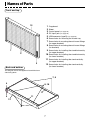
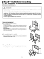
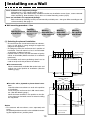
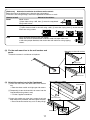
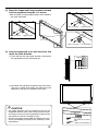
Copyboard M-5
User’s Manual (CD-ROM Edition)
Thank you for your purchase of the PLUS Copyboard.
Please read this User’s Manual (CD-ROM Edition) carefully before use
to take full advantage of the functions of this product. After you have
finished reading the manual, please keep it for future reference.
1
Trademarks
• Microsoft and Windows are registered trademarks or trademarks in the United States and other countries of the Microsoft
Corporation.
• IBM and PC/AT are registered trademarks of International Business Machines Corporation of the United States.
• Adobe and Adobe Acrobat Reader are trademarks of Adobe Systems Incorporated.
• CompactFlash and CF are trademarks of SanDisk.
The trademarks of the various companies and the product trademarks, even when not written down, will be given due respect.
Product names and company names appearing in this manual are registered trademarks or trademarks of the respective companies.
(1) The contents of this manual may not be reprinted in part or whole without permission.
(2) The contents of this manual are subject to change without notice.
(3) Great care has been taken in the creation of this manual; however, should any questionable points, errors, or omissions be
apparent, please contact us.
(4) Notwithstanding Section (3), this company will not be responsible for any claims of loss or profit or other matters deemed to be
the result of using this unit.
(5) Manuals with incorrect collating or missing pages will be replaced.
2
Table of Contents
IMPORTANT SAFETY INFORMATION ------------------------------------------------------------ 4
Packaged Contents ------------------------------------------------------------------------------------ 6
Names of Parts ------------------------------------------------------------------------------------------ 7
Installation and Assembly Instructions -------------------------------------- 8
Read This Before Installing -------------------------------------------------------------------------------------- 9
Cautions on Installation -------------------------------------------------------------------------------------------------------- 9
Types of Installation ------------------------------------------------------------------------------------------------------------- 9
Installing on a Wall ------------------------------------------------------------------------------------------------ 10
Installing on a Stand --------------------------------------------------------------------------------------------- 13
Assembling the stand and mounting the copyboard horizontally -------------------------------------------------- 13
Assembling the stand and mounting the copyboard vertically ----------------------------------------------------- 15
Installing on a Partition-Panel -------------------------------------------------------------------------------- 17
Assembly and installation ---------------------------------------------------------------------------------------------------- 17
Operation Instructions ---------------------------------------------------------- 19
Usage Guide -------------------------------------------------------------------------------------------------------------------- 19
Names of Main Unit Controls and Connectors ---------------------------------------------------------- 20
Handling CF Memory Cards ------------------------------------------------------------------------------------------------ 21
Scanning area ------------------------------------------------------------------------------------------------------------------ 21
Operating the Copyboard -------------------------------------------------------------------------------------- 22
Connecting the AC power adapter and turning the power on and off -------------------------------------------- 22
Saving the Image on the Sheet -------------------------------------------------------------------------------------------- 23
Saving sheet images in the built-in memory ----------------------------------------------------------------------- 23
Saving sheet images on a CF memory card ---------------------------------------------------------------------- 24
Clearing the built-in Memory ------------------------------------------------------------------------------------------------ 25
Scrolling the Sheet ------------------------------------------------------------------------------------------------------------ 25
Vertical/Horizontal Position Setting ---------------------------------------------------------------------------------------- 25
Storing Image Files on a Computer ------------------------------------------------------------------------- 26
Storing/Deleting Directly with USB Connections (from built-in memory or CF memory card) -------------- 26
Using a PC Card Adapter or Memory Card Reader/Writer (USB type) ------------------------------------------ 30
Using a PC card adapter ----------------------------------------------------------------------------------------------- 30
Using a memory card reader/writer (USB type) ------------------------------------------------------------------ 31
Troubleshooting --------------------------------------------------------------------------------------------------- 32
Specifications ------------------------------------------------------------------------------------------------------ 33
Quick Calibration -------------------------------------------------------------------------------------------------- 34
Software Guide --------------------------------------------------------------------- 35
Before Using the Software ------------------------------------------------------------------------------------- 36
Software Contents and Overview ------------------------------------------------------------------------------------------ 36
Operating Environment ------------------------------------------------------------------------------------------------------- 36
Windows 98SE Personal Computer and USB Connections ---------------------------------------- 37
Driver Setup (Windows 98SE) ---------------------------------------------------------------------------------------------- 37
Uninstalling the Driver (Windows 98SE) --------------------------------------------------------------------------------- 38
Windows Me / 2000/ XP Personal Computer and USB Connections ----------------------------- 39
Disconnecting of the Copyboard ---------------------------------------------------------------------------- 40
Windows 98SE ----------------------------------------------------------------------------------------------------------------- 40
Windows Me / 2000 / XP ----------------------------------------------------------------------------------------------------- 40
M-5 Setup Utility --------------------------------------------------------------------------------------------------- 41
Installation ----------------------------------------------------------------------------------------------------------------------- 41
Starting up ----------------------------------------------------------------------------------------------------------------------- 41
Electronic User’s Manual --------------------------------------------------------------------------------------- 42
Acrobat Reader Installation ------------------------------------------------------------------------------------------------- 42
Opening the M-5 User’s Manual ------------------------------------------------------------------------------------------- 42
PLUS Image Viewer ----------------------------------------------------------------------------------------------- 43
Installation ----------------------------------------------------------------------------------------------------------------------- 43
Starting up ----------------------------------------------------------------------------------------------------------------------- 43
Deleting the Software -------------------------------------------------------------------------------------------- 44
3
IMPORTANT SAFETY INFORMATION
WARNING
The unit’s rear panel should never be opened by anyone other than a qualified serviceperson. There are
many high voltage parts inside the unit, and touching them is dangerous. For replacement of the light
source, internal inspections, adjustments, repairs or internal cleaning, please contact your store of purchase.
CAUTION
Continued use of the unit under abnormal conditions (when the unit is emitting smoke, unusual odors or
sounds) could lead to fire or electric shocks.
Turn off the unit’s power immediately, then unplug the AC power adapter from the power outlet.
Check that no more smoke, etc., is being emitted, then contact a sales outlet for repairs.
Repairing the unit yourself is dangerous. Never attempt to do so.
WARNING
This is a FCC class A product. In a home environment this product may cause radio interference in which case the
user may be required to take adequate measures.
This symbol warns the user that uninsulated voltage within the unit may have sufficient magnitude to cause electric shock.
Therefore, it is dangerous to make any kind of contact with any part inside of this unit.
This symbol alerts the user that important literature concerning the operation and maintenance of this unit has been
included. Therefore, it should be read carefully in order to avoid any problems.
SAFETY PRECAUTIONS
Heeding the safety precautions below will lengthen the product’s service life and prevent fires, electric shocks and injury. Read these
safety precautions carefully and be sure to heed them.
Handling the AC power adapter
•
•
•
•
Do not connect any AC adapter other than the dedicated one to the unit. Doing so could result in fire or other accidents.
Do not use with voltages other than the voltage indicated. Doing so could result in fire or electric shock.
Do not let the AC power adapter get wet. Doing so could result in fire or electric shock.
Do not subject the AC power adapter to shocks. Doing so could result in fire or electric shock.
Handling the AC power adapter’s cord and plug
• Damaging the power cord could lead to fire or electric shock.
* When installing, do not squeeze the power cord between the product and a wall, rack, etc.
* Do not modify or damage the power cord.
* Do not place heavy objects on the power cord or pull strongly on it.
* Do not place the power cord near heating appliances or otherwise heat it.
* When unplugging the power cord, always do so by pulling on the plug, not the cord.
If the power cord should be damaged, ask your store of purchase to replace it.
• If there is dust or metal objects on or near the power plug’s blades, unplug the power cord then wipe the blade area clean using a
dry cloth. Continued use without cleaning the plug could lead to fire or electric shock.
• Do not plug in or unplug the power cord with wet hands. Doing so could lead to electric shock.
• When moving the unit, turn off the power and be sure to unplug the power cord from the AC outlet first. Moving the unit with the
power cord plugged in could damage the cord, leading to fire or electric shock.
• Connect the power plug securely to the AC outlet, pressing the blades in to the hilt. Uncomplete plugging could cause heating or
attract dust, leading to fire. In addition, touching the plug’s blades could cause electric shock.
4
Do not use the included CD-ROM in a player designed for audio CDs.
• Never use the included CD-ROM in a player designed for audio CDs. Doing so could produce loud noises that could impair your
hearing. These noises can also damage your speakers.
Installation
• When the copyboard is mounted on a stand, be sure to lock the casters.
• When mounting on a wall, be sure to check first that the wall surface is strong enough to support the total weight of the main unit
and mount fittings over a long period of time (including during earthquakes). If the wall is not strong enough, reinforce it before
mounting the unit.
• Getting water on or inside the unit etc., could lead to fire or electric shock. Be particularly careful when using the unit near a window
when it is raining or snowing and when using it near the shore of the ocean and lakes.
• Do not set the unit in hot places exposed to direct sunlight or in places exposed to wind coming directly from an air conditioner.
Do not set the unit in places exposed to soot or humidity (on kitchen counters, near humidifiers, etc.).
Preventing Tipping (when mounted on a stand)
To prevent tipping, heed the instructions below. Tipping could lead to personal injury or damage the unit.
• Place the unit on a flat floor.
• Lock the casters when using the unit. When moving it, be sure to unlock the casters to prevent tipping.
• Do not lean against the unit or apply excess force to the top of the unit.
Care and Cleaning
Cautions on Usage
• Take care that the unit does not get wet and that water does not get inside. Do not place objects containing chemicals, water or
other liquids (vases, potted plants, glasses, cosmetics, etc.) on top of the unit. The liquid could spill and get inside the unit, leading
to fire or electric shock.
• When lifting the unit to hang it on the stand, etc., the unit should be lifted by at least two persons to prevent it from tipping and
causing personal injury.
• Do not move the sheet with paper or other objects attached to it. Doing so could cause damage.
• Do not wipe the unit or sheet with thinner, benzene, alcohol or other such products. Doing so could cause discoloration or damage
the sheet.
• Only use markers designed exclusively for this product.
Using other markers could damage the sheet. Also note that it may not be possible to erase the ink of other markers.
• When moving the unit mounting on the stand, be sure to unlock the casters, then support the unit from both sides and move it
gently and carefully to avoid shocks.
• When not using for long periods of time, for safety be sure to unplug the AC power adapter from the power outlet.
Handling the CD-ROM
• Do not touch the surface on which nothing is printed (the surface on which the data is recorded). If this surface is dirty the data will
not be read properly.
Also, do not stick paper, stickers, etc., on the CD-ROM.
• Do not leave for long periods of time in places exposed to direct sunlight or near heating appliances, and do not drop or bend the
CD-ROM. The disc may get warped, making it impossible to read the data.
Cleaning
• If the sheet is dirty, wipe it clean using a damp, thoroughly wrung out cloth. For tough dirt, apply some diluted neutral detergent to
a cloth, wipe off the dirt, then wipe again to remove any detergent.
Wait until the sheet is completely dry before using it.
• Do not wipe the copyboard or sheet with thinner, benzene, alcohol, etc. Doing so could cause discoloration or damage the sheet.
• Use a damp, thoroughly wrung out cloth to wipe any dust of markers on the marker tray or the frame.
5
Packaged Contents
The contents included in the package are described below. Make sure that all items are included before starting.
Copyboard (main unit) … 1
쮿 Accessories included with copyboard
• Set of markers … 2 (black and red)
• Marker tray (1 set)
Use these special markers to draw or write on the sheet.
Put the markers and the eraser on this tray (when the
copyboard is installed horizontally).
(Includes 2 side covers and 3 M4 x 8 screws)
* Please remove the marker tray that is fixed on the M-5
upside down for the transportation.
(Please keep three screws so that you can use them to
fix the tray at the normal position.)
• Eraser … 1
Use this to erase what you have drawn or written.
(screws removed from the
Copyboard when unpacking)
• AC power adapter (with 3 meter power cord) … 1
This is the power adapter for supplying power to the
copyboard.
• Wall mount fittings (1 set)
Use these fittings to mount the copyboard to a wall.
(1 wall mount bar, 2 upper brackets, 2 lower brackets, 8 M4
⳯ 12 bracket mounting screws)
Upper brackets
Lower brackets
• USB cable (type B 씯씮 type A, 3 meters) … 1
Use this cable to connect the copyboard with a computer.
쮿 Documents
• Phillips screwdriver ... 1
Operating instructions (simplified version) … 1
Wall mount positioning sheet … 1
CD-ROM … 1 (including operating instructions (in PDF
Use this when setting up the
Copyboard.
format), Windows 98SE driver and PLUS Image Viewer)
• Cosmetic seals ...1 sheet for 11 pieces
To cover screw holes and screws, peel a cosmetic seal from
the backing sheet and apply it.
6
Names of Parts
Front and top
12
1. Copyboard
2. Sheet
3. Control panel (see page 20)
4. DC input jack (see page 20)
5. USB connector (type B) (see page 20)
6. Screw holes for mounting the marker tray
7. Screw holes for mounting the wall mount fittings
(for upper brackets)
8. Screw holes for mounting the wall mount fittings
(for brackets)
9. Screw holes for installing the stand horizontaly
1
(for upper brackets)
2
10. Screw holes for installing the stand horizontaly
(for lower brackets)
11. Screw holes for installing the stand vertically
(for upper brackets)
3
12. Screw holes for installing the stand vertically
(for lower brackets)
Back and bottom
This diagram shows the copyboard set with the front
side facing down.
7, 9
4
8, 10
11
5
11
12
6
7
Installation and
Assembly
Instructions
To the Customer
Specialized techniques are required in the wall mounting of the
Copyboard. Please do not attempt any installation work unless
you have the techniques.
To the Dealer or Installation Tradesman
In the interest of the safety of the customer, please perform installation work paying due attention to the strength of the installation
location to ensure that it can bear the load of the Copyboard and
installation parts.
8
Read This Before Installing
Cautions on Installation
WARNINGS
• Be sure to install and assemble the copyboard as instructed in this manual. Improper installation or assembly
could lead to injury.
• At least two people should hold the copyboard when installing and removing it.
• To prevent the copyboard from falling off the wall, install the copyboard on a sufficiently strong surface and in
such a way that the weight of both the copyboard and the mounting hardware can be supported for an extended
period of time, even in earthquakes. Improper installation could lead to the copyboard falling and causing injury.
• Use M6 screws or the equivalent to fix the copyboard to the wall. If any other screws are used, the copyboard
could fall, causing injury.
• Install on a wall surface reinforced by sturdy studs.
• When installing on a concrete wall, use anchor nuts and anchor bolts.
Types of Installation
On a wall (horizontal or vertical)
Horizontal Position:
Use the wall mount fittings included with the copyboard to mount the
unit directly on the wall. The copyboard can be installed in the horizontal direction.
Vertical Position:
Use of the vertical wall mounting kit allows the Copyboard to be installed in the vertical orientation. (Vertical wall mounting kit: Model M5- W, order code 44-563)
On a stand (horizontal or vertical)
Mount the copyboard on an optional stand for mobility. The copyboard
can be mounted in either the horizontal or vertical position. (Stand Kit
: Model M-5-T, order code: 44-562)
On a partition-Panel
Use an optional partition mount kit to hang the copyboard onto a partition panel. (Partition hanger Kit : Model M-5-P, order code: 44-552)
9
Installing on a Wall
Parts included in the copyboard package:
Wall mount bar (1 pc), upper brackets (2 pcs),
Marker tray (1 pc, with 2 side covers) and M4 x 8 marker tray installation screws (3 pcs, screws removed
when unpacking), lower brackets (2 pcs), M4 x 12 bracket mounting screws (8 pcs)
Parts not included in the copyboard package:
Bolts and nuts for fastening to wall (use commercially available parts – the types differ according to wall
surface material). See page 11.
Wall mounting procedure – flow
Selecting the place
of installation
Preparing
the wall surface
Mounting the wall
mount bar
Mounting
the brackets
on the copyboard
Mounting
the marker tray
on the copyboard
Mounting
the copyboard
onto the wall
(1) Selecting the place of installation
• The wall mount bar should be mounted on columns,
posts, or wall which is strong enough to support the
weight of the copyboard.
• The diagram shows the wall mount bar’s position of
installation. The wall mount bar has 8 mm diameter
screw holes at 100 mm intervals.
• Choose holes in such a way that the center of gravity
will be at the middle. (Make sure there is no extreme
imbalance.)
• The included “wall mount positioning sheet” can be
used to easily mark the position of installation.
800
100
100
100
100
100
100
100
100
Position of upper
bracket (hook)
Wall mount bar mounting
position
For concrete walls
Mount commercially available M6 anchor bolts and
anchor nuts to the position of installation. (See the
following page.)
663
300 (275 - 330)
655
Position of lower
bracket
Column, stud, etc.
For walls with a plywood or plaster board structure
Check that there are columns or studs at the position
of installation.
Install using the wall mount bar’s M6 wood screws,
etc. (See the following page.)
Mount the lower brackets in the position on the diagram shown for the wood screws for when installing
the copyboard.
Notice:
• For structures with no columns, use a separately sold
stand.
An optional partition mount kit is also available for mounting the copyboard on a partition panel.
10
100
100
100
800
100
100
100
100
100
Position of upper
bracket (hook)
Wall mount bar mounting position
663
655
Wooden or thick
plywood wall
Position of lower
bracket
[Reference] Method of installation for different wall materials
Select the type of installation best suited for the wall material.
If the wall is not strong enough, mount the copyboard to columns or studs.
Material of wall
Method of installation
1
2
Wood
Wood screws:
햲Open holes using a drill, then 햳 mount the copyboard
using wood screws.
Concrete
U-plugs:
햲 Open the base hole in the wall using a drill, 햳 insert the U-plug, then 햴 fasten the wall
mount bar using screws.
1
Steel
2
3
Cross recessed tapping screw (pan head):
Check that there is reinforcement inside the steel wall, open holes with
a drill of the proper diameter, then mount the wall mount bar using tapping
screws.
(2) Fix the wall mount bar to the wall surface and
posts.
Mounting on the wall surface
• Fasten the screws in a minimum of 3 places.
M6 screw
Mounting on a post
M6 wood screw
(3) Attach the marker tray to the Copyboard.
햲 Insert the side covers into both ends of the marker
tray.
• Note that there are left and right type side covers.
햳 Temporarily fasten the three M4 x 8 screws into the
Copyboard (leaving about 3 mm)
• Use the supplied screwdriver.
햴 Insert the marker tray over the 3 screws that have
been temporarily fastened, and then tighten securely.
• Please insert the marker tray as far as they will go.
Side covers
1
3
2
M4 x 8 screws
3
Marker tray
11
(4) Mount the 2 upper and 2 lower brackets included
with the copyboard using M4 x 12 screws.
• Both of the left and right upper brackets are installed in
the same orientation.
M4⳯12 screws
M4⳯12 screws
Upper bracket
M4⳯12 screws
Lower bracket
Upper bracket
(5) Hang the copyboard to the wall mount bar and
fasten the lower brackets.
햲 Catch the left and right upper brackets mounted on
the copyboard onto the wall mount bar.
Upper bracket
Wall mount bar
햳 Fix the left and right lower brackets to the wall surface.
(The way in which the brackets are fixed to the wall
depends on the type of installation to the wall.)
Lower brackets
CAUTION
• The upper brackets are not fastened. Do not let the
copyboard slide too much when fixing the lower brackets. Doing so may cause the copyboard to come off the
wall mount bar and fall, resulting in injury.
• At least two people should hold the copyboard to prevent it from dropping or tipping over, resulting in unexpected injury.
12
Wood screw or anchor
bolt
(M6 or the equivalent)
Installing on a Stand
The optional stand kit for both vertical and horizontal installation (Model M-5-T, order code 44-562) is required to
install the copyboard on a stand.
Assembling the stand and mounting the copyboard horizontally
Parts included in the copyboard package: Marker tray (1 pc), side covers (2 pcs), M4 x 8 marker tray installation
screws (3 pcs, screws removed when unpacking), 8 copyboard mount screws (M4 x 12)
List of parts included in the stand kit (parts used for horizontal installation)
Feet (with casters) : 2, Frames : 2, Foot washers : 2, Foot fixing screws (M8 x 50) : 4, Spring washers : 4,
Extension frames : 2, Caps : 6, Fixing knobs (with hexagon cap nuts) : 2, Crossbars : 2,
Hexagonal socket head screws : 4, Flat washers : 4, Upper brackets (left and right) : 2, Lower brackets : 2,
Hexagonal wrench (M8) : 1, Hexagonal wrench (M5) : 1
Assembly and installation flow
Assembling
the stand
Mounting
the marker tray
on the copyboard
Mounting the
copyboard
onto the stand
Mounting
the brackets
on the copyboard
(1) Assemble the T-shaped legs (two).
Spring
washer
Cap
햲 Mount the foot using washers, spring washers and M8 x 50 hexagonal socket head
screws.
3
Extension frame
Foot washer
2
햳 Make sure of the orientation of the extension frame
and the frame end looking at the marks, then insert
all the way. (Note that it will no longer be possible to
remove the extension frame when the mark surface has been inserted in the opposite orientation.)
Notice:
• Mounting the extension frame makes for a height
of 1700 mm off the floor (compared to 1465 mm
without the extension frame). Use this to adjust
the height.
• For the assembly procedure when not mounting
the extension frames, see step (1) under “Assembling the stand and mounting the copyboard vertically”.
햴 Fit the caps on the top of the frame and feet.
(2) Mount the two crossbars onto the T-shaped
legs assembled in (1) above.
Mount them using the M5 hexagonal socket head
screws and flat washers.
Temporarily fasten the screws using the included M5
hexagonal wrench, then fasten them securely once
both the upper and lower crossbars have been
mounted.
M8 x 50 hexagonal
socket head screw
Frame
M8 hexagonal wrench
3
1
Cap
Cap
Foot
3
Crossbar
Flat washer
M5 hexagonal
socket head
screw
T-shaped leg
M5 hexagonal
wrench
* Assemble in a flat place.
Crossbar
13
(3) Attach the marker tray to the Copyboard.
Side covers
* The marker tray is fixed on the M-5 upside down for
the transportation. Please remove it before you
assemble the M-5, and then fix it again at the normal
position. (Please make sure the orientation of the
marker tray.)
1
3
햲 Insert the side covers into both ends of the marker
tray.
• Note that there are left and right type side covers.
2
M4 x 8 screws
햳 Temporarily fasten the three M4 x 8 screws into the
Copyboard (leaving about 3 mm)
• Use the supplied screwdriver.
3
햴 Insert the marker tray over the 3 screws that have
been temporarily fastened, and then tighten securely.
• Please insert the marker tray as far as they will
go.
Marker tray
Upper bracket (Rightt)
(4) Mount the upper and lower brackets using M4
x 12 screws.
• The left and right upper brackets are different. Be sure to mount them on the proper
side.
• Both the lower brackets have the same
form, but mount them in the opposite directions so that each is facing outwards.
Upper bracket (Left)
M4⳯12 screws
M4⳯12 screws
Lower bracket
M4⳯12 screws
(5) Hook the left and right upper brackets of the
Copyboard onto the upper crossbar and fasten the lower brackets using the fixing knobs
and hexagon cap nuts.
Fixing knobs
CAUTION
• Lock the casters so that the stand does not move.
• When mounting and adjusting the height, at least
two people should hold the copyboard to prevent it
from dropping or tipping over, resulting in unexpected injury.
Hexagon cap nuts
14
Assembling the stand and mounting the copyboard vertically
Parts included in the copyboard package: 6 copyboard mount screws (M4 x 12)
List of parts included in the stand kit (parts used for vertical installation)
Feet (with casters) : 2, Frames : 2, Foot washers : 2, Foot fixing screws (M8 x 50) : 4,
Spring washers : 4, Caps : 6, Fixing knobs (with hexagon cap nuts) : 2, Crossbars : 2,
Hexagonal socket head screws : 4, Flat washers : 4, Upper brackets (left and right) : 2, Lower brackets : 2,
Hexagonal wrench (M8) : 1, Hexagonal wrench (M5) : 1, Short marker tray:1, Side covers: 2
M3 decorative screws : 2
Assembly and installation flow
Assembling
the stand
Mounting
the brackets
on the copyboard
Changing the
Mounting the
vertical marker tray image storing
setting to “vertical”
on the copyboard
Mounting
the copyboard
onto the stand
(1) Assemble the T-shaped legs (two).
햲 Mount the foot using two M8 x 50 screws (+ spring
washers).
햳 Fit the caps on the top of the frame and feet.
Spring
washer
Cap
2
Foot washer
M8 x 50 hexagonal
socket head screw
Frame
M8 hexagonal wrench
2
1
Cap
Cap
Foot
2
(2) Mount the two crossbars onto the T-shaped legs
assembled in (1) above.
Mount them using the hexagonal socket head
screws and flat washers.
Temporarily fasten the screws using the included
hexagonal wrench, then fasten them securely once
both the upper and lower crossbars have been
mounted.
Crossbar
Flat washer
M5 hexagonal
socket head
screw
T-shaped leg
* Assemble in a flat place.
M5 hexagonal
wrench
Crossbar
15
(3) Mount the upper and lower brackets
using M4 x 12 screws.
• The left and right upper brackets are different.
Be sure to mount them on the proper side.
Upper bracket
M4 x 12
screws
M4 x 12
screws
Lower bracket
(4) Hook the left and right upper brackets of the Copyboard onto the upper crossbar and fasten the lower
brack-ets using the fixing knobs
and hexagon cap nuts.
There are two screw holes for adjusting
the angle (upright or 10 degrees) on each
lower bracket. Use the desired screw
holes.
To mount at a 10º angle
CAUTION
To mount upright
• Lock the casters so that the stand does
not move.
• When mounting and adjusting the height,
at least two people should hold the
copyboard to prevent it from dropping or
tipping over, resulting in unexpected injury.
Hexagon
cap nuts
Fixing knobs
(5) Mount the short marker tray.
햲 Peel off the two cosmetic seals to expose the
screw parts.
햳 Insert the side covers into both ends of the short
marker tray.
• Note that there are left and right type side
covers.
햴 Temporarily fasten the two M3 decorative
screws to the Copyboard (leaving about 3 mm).
햵 Insert the marker tray over the two screws that
have been temporarily fastened, and tighten securely.
• Please insert the short marker tray as far as
they will go.
Short marker tray
Cosmetic seals
1
3
M3 decorative screws
Side covers
(6) Change the direction of image data (“POSITION”) to “vertical”.
2
4
This sets the direction in which the images are
stored. (See page 25.)
16
Installing on a Partition-Panel
The optional partition hanger kit (Model M-5-P, order code 44-552) is required to install the copyboard on a partitionpanel.
Assembly and installation
Parts included in the copyboard package : Marker tray (1 pc), side covers (2 pcs), M4 x 8 marker tray installation
screws (3 pcs, screws removed when unpacking)
List of parts included in the partition hanger kit
Partition hangers : 2, Hanger brackets : 2, Hooks : 2, M4 x 12 screws : 8 , M4 x 8 flat head screws : 4 ,
M4 x 6 screws : 4
Assembly and installation flow
Mounting
the marker tray
on the copyboard
Mounting
the partition hangers
on the copyboard
Mounting the hanger
brackets and hooks
on the partition hangers
Mounting
the copyboard
on the partition
(1) Attach the marker tray to the Copyboard.
* The marker tray is fixed on the M-5 upside down for
the transportation. Please remove it before you
assemble the M-5, and then fix it again at the normal
position. (Please make sure the orientation of the
marker tray.)
햲 Insert the side covers into both ends of the marker
tray.
• Note that there are left and right type side covers.
Side cover
1
3
2
M4 x 8 screws
햳 Temporarily fasten the three M4 x 8 screws into the
Copyboard (leaving about 3 mm)
• Use the supplied screwdriver.
햴 Insert the marker tray over the 3 screws that have
been temporarily fastened, and then tighten securely.
• Please insert the marker tray as far as they will
go.
3
Marker tray
(2) Mount the partition hangers onto the
copyboard (fasten at 4 spots).
Use the
M4 x 12 screws (2 each).
Partition hanger
M4 screws
M4 screws
17
(3) Mount the hanger brackets to the screw holes at the
middle of the partition hangers (left and right).
• Use the
M4 flat head screws.
• The partition hangers have screw holes for mounting hanger
brackets at both the top and middle. Use the top holes when
mounting the copyboard on a tall panel.
Tall panel mount position
Hanger bracket
Hanger bracket
M4 x 8 flat head screws
M4 x 8 flat head screws
(4) Mount the hooks (2) to the tops of the hanger brackets using
M4 x 6 screws (2 each).
• First fasten the hooks loosely to the maximum width of 60 mm
to make it easier to hang the copyboard on the panel.
• The hanger brackets can be used for panels of 50 to 60 mm
thickness.
M4 x 6 screws
Hook
Hooks
(5) Mount the copyboard on the partition
panel.
Catch the hooks onto partition panel.
Take the panel in the hooks so as to fit snugly to
the thickness then fully tighten the hooks’ screws.
Partition panel
WARNING
• The copyboard sits freely on the partition, it is not fixed to it. Do not push the copyboard upwards or otherwise
lift it. Doing so may cause it to come off the partition and drop.
CAUTION
• If the partition panel is not stable, take the necessary measures to keep it from tipping over, by for example
fastening its feet or struts to the floor, etc.
18
Operation Instructions
This manual contains information pertaining to the
copyboard.
For instructions on the included software, please refer
to the software’s help file.
Usage Guide
Saving and Transferring images
If you need to save a copy of what you have written on the copyboard, you
can store it in the built-in memory. (page 23)
The image data stored in the built-in memory or on a CF memory card can
be transferred directly to a computer using USB connections. (page 26)
Storing images on CF memory cards
In addition to the built-in memory, large amounts of data can be stored on
CF memory cards or on computers. (page 24, 26)
The data stored on CF memory cards can be stored on a computer either by
using a commercially available PC card adapter or CF card reader/writer, or
directly with USB connections when the CF memory card is inserted into the
copyboard’s card slot.(page 26)
Editing and printing images
Files stored in the built-in memory or on a computer can be edited, deleted
or printed using the imaging software of Windows, the “PLUS Image Viewer”
utility contained in the CD-ROM or other image editing programs you may
have. (page 43)
Applications of copyboard data
The data can be sent as e-mail attachments.
It can also be converted into data formats that can be used to create or edit
documents using the “PLUS Image Viewer” contained in the CD-ROM or
other image software you may have. (page 43)
19
Names of Main Unit Controls and Connectors
햸
RY
MO
ME
The connectors are located
on the bottom side of the
copyboard.
햻
햵
햴
ED P
FE /STO
햶
햺
R
WE
PO
When set vertically
햳
햲
R
EA
CL
햷
ION
The connectors are
located on the left side
of the copyboard.
SIT
PO
RY
MO
ME
햳 POWER indicator (Green)
This lights when the power is turned on and turns off
when the power is turned off. The indicator flashes to
indicate errors or the operating status.
ED P
FE /STO
R
WE
PO
R
EA
CL
ION
SIT
PO
햲 POWER button
Use this to turn the power on and off.
햹
햷 CLEAR button
Use this to clear all the image data in the built-in
memory (when pressed for at least 3 seconds).
햸 Card slot
This card slot is exclusively for CF memory cards.
햴 MEMORY button
Use this to save drawings, words, etc., you have drawn
or written on the sheet surface into the memory.
햹 POSITION button
(pin hole – button is located at bottom of hole)
Use this to switch the image to be stored in the memory
between the vertical and horizontal mode.
햵 MEMORY indicator (Amber)
This blinks when the data is being stored in the
memory. Depending on the speed at which it is blinking, it may also indicate an error.
햺 DC power jack
Connect the DC side of the AC power adapter here.
(Never connect anything other than the dedicated AC
adapter.)
햶 FEED/STOP button
Use this to automatically feed 1 sheet or to stop feeding.
햻 USB connector (type B)
Connect this to a computer’s USB port (type A).
Notice:
Indicator blinking frequencies and terms used in this manual
The blinking of the indicators is used to indicate both the copyboard’s operating status and errors. In this manual the
frequencies are expressed as shown below.
Terms in manual
Blinking frequency
Diagram of flashing
Blinking slowly
Lit 0.5 seconds, off 0.5 seconds
Blinking quickly
Lit 0.25 seconds, off 0.25 seconds
Blinking intermittently
Lit 0.25 seconds, off 0.25 seconds,
lit 0.25 seconds, off 1.25 seconds
The (amber) Memory indicator and the (green)
Power indicator blink alternately at high rate.
Error blinking
20
Handling CF Memory Cards
• We recommend backing up data stored in the built-in memory or on CF memory cards onto other recording media
periodically to secure the data in case of damage or loss.
• Note that PLUS will accept no responsibility whatsoever for loss or damage of stored data.
• Please use a memory card having specifications that conform with the CompactFlash standard (which supports an
operating voltage of 3.3 V / 5 V).
* CompactFlash memory cards are referred to as “CF memory cards” in this manual.
Inserting CF memory cards
When using in the horizontal position
With the surface of the CF memory card facing the left, insert
the card vertically, pressing it slowly to the end.
O
E
R
Y
M
M
P
MEMO
R
W
RY
O
FEED/STOP
E
P
POWE
R
L
E
A
R
R
C
CLEA
POSIT
ION
When using in the vertical position
With the surface of the CF memory card facing the up, insert
the card horizontally, pressing it slowly to the end.
D O
E T
E
F /S
N
IO
IT
O
S
P
Note:
• Insert the CF memory card slowly.
• The slot is designed so the card cannot be inserted in the wrong
direction. Trying to force it will result in damage.
Removing the CF memory card
Check that the MEMORY indicator has stopped blinking and turned
off, then pull the CF memory card out.
MEMO
Y
R
O
M
E
M
RY
FEED/STOP
POWE
P
D O
E T
E
F /S
R
R
POSIT
ION
R
E
W
O
P
CLEA
Note:
• Do not pull off the CF memory card or disconnect the AC power
adapter’s cable while data is being stored in the memory (when
the MEMORY indicator is blinking). Doing so will damage the
data.
The CF memory card can be replaced while the MEMORY indicator is blinking intermittently, indicating there is not enough
free memory left.
R
A
E
L
C
N
IO
IT
S
O
P
Scanning area
Notes on scanning the sheet surface
Effective scanning area
Scanning is not possible on the edges of
sheet. Write or draw within the effective
scanning area.
Notice: The effective vertical scanning area
is within the ruled lines.
20mm
Area not scannable
23.5mm
20mm
978mm
578mm
23.5mm
Effective scanning area
• When the POWER button is press to turn on the power or the
MEMORY button is pressed while in the standby mode, the
memory or feed operation starts after the warm-up. It is for stable
sanning condition.
Under normal conditions, it takes about 20 seconds, but under
certain environments, for example when the external temperature
is low, some more time may be required. On this copyboard, this
warm-up time is controlled by a timer and it can be changed with
the setup utility.
To achieve a more stable picture quality, we recommend you to
wait one minute after the fluorescent lamp turns on before storing
images in the memory. The time required for operation to become
stable depends on the environment.
• Note that images may not be read as well if you use markers of
colors other than black and red or markers of other brands. Use
the markers specified by PLUS.
• Avoid use in places exposed to abrupt changes in temperature
such as near the vents of an air conditioner.
Doing so could result in the deterioration of read quality.
21
Operating the Copyboard
These operations are required when storing the drawings on the copyboard’s sheet in the memory and when moving
the sheet surface using the buttons.
Connecting the AC power adapter and turning the power on and off
The diagrams used in the explanations below show the
copyboard installed in the horizontal position.
Connect the AC power adapter.
햲 Connect the AC power adapter to the copyboard’s DC
power jack.
햳 Connect the AC power cord to the AC power adapter.
Insert plugs securely
햴 Plug the AC power cord into a AC power outlet in a wall.
1
The explanations below assume this condition.
AC power outlet
AC power cord
AC power adapter
Press the POWER button to turn on the power.
The POWER indicator blinks for approximately 20 seconds, then
stops blinking, remaining lit. The copyboard is now ready to scan
images (the fluorescent lamp is lit).
Drawings on the copyboard’s sheet can now be stored in the
memory.
3
2
MO
RY
ME
ED P
FE /STO
R
WE
PO
Notice:
• The power mode changes to the standby if no button is operated for 30 minutes.
• When in the standby mode, the corresponding function is performed when a button is pressed.
R
EA
CL
ION
SIT
PO
When not using the copyboard
R
WE
Press the POWER button to turn the power off. The POWER indicator turns off.
PO
Notice:
The built-in memory or CF memory card can be accessed if the
USB cable is connected to a computer in this status.
CL
R
EA
ION
SIT
PO
Note:
• When disconnecting the AC power adapter, first unplug the
power cord from the AC power outlet in the wall.
• Unplug the power cord from the wall outlet when not planning
to use the copyboard for long periods of time.
22
Saving the Image on the Sheet
Images drawn on the sheet can be stored either in the built-in memory or on a CF memory card.
This is a black and white copyboard. Images drawn in color are stored in black and white.
䡵 Saving sheet images in the built-in memory
Preparations: Check that the POWER indicator is lit. If it is off, press the POWER button.
The diagrams used in the explanations below show the
copyboard installed in the horizontal position.
Press the FEED/STOP button to move the sheet image you want to
save to the front.
• There is no need to perform this operation to save the image that is currently
at the front.
• When the FEED/STOP button is pressed, the sheet scrolls one page’s worth
to the left (or upwards) (this takes about 12 seconds), then stops automatically. To stop in the middle, press the FEED/STOP button again. (page 25)
MO
ME
ED P
FE /STO
R
WE
PO
Press the MEMORY button to store that image in the memory.
• The sheet scrolls one page’s worth to the left (or upwards), scanning starts,
and the image is stored in the built-in memory.
• The MEMORY indicator blinks slowly while the image is being stored in the
memory.
● If the indicator blinks intermittently
The indicator blinks intermittently (warning) when there is not enough free data
space left in the built-in memory.
* Either clear the built-in memory (see “Clearing the built-in memory” on page
25) or insert a CF memory card with enough free space on it, then press the
MEMORY button again.
If the indicator starts blinking intermittently (warning) after scrolling
* The memory may run out of space while the file is being stored. In this case,
the data that was scanned is still in the memory when the indicator starts
blinking intermittently.
* To store the data in a file, insert a CF memory card with enough free space
on it, then press the MEMORY button.
* Note that the data is discarded when the memory clearing procedure is
performed or when the FEED/STOP or POWER button is pressed.
* To save the same image again, bring that sheet surface back to the front,
then press the MEMORY button.
RY
MO
ME
ED P
FE /STO
R
WE
PO
R
EA
CL
ION
SIT
PO
Notice:
• If a CF memory card is inserted into the card slot, the data is stored on the CF memory card, not in the built-in
memory.
• The edges of the image on the sheet surface are not stored. See “Scannable area” on page 21.
• Some parts may not be read or their density built-in in the data may change (patchy letters, thin lines, portions
where marker lines overlap, etc.).
• To save image files stored in the built-in memory onto a computer, see page 26.
• The maximum capacity of the built-in memory is about 1.8 MB, that is between 15 and 20 files (the amount
of data per file depends on the drawings on the sheet).
• Do not press the FEED/STOP button while the image is being scanned (while the MEMORY indicator is
blinking slowly). Doing so will cancel the data saving procedure and the data will be discarded.
• To move the sheet surface, press the FEED/STOP button after scrolling has stopped.
• The date of file property is fixed at January 1, 2004.
This can be changed using the “M-5 setup utility” software.
23
䡵 Saving sheet images on a CF memory card
Preparations: Check that the POWER indicator is lit. If it is off, press the POWER button.
The diagrams used in the explanations below show the
copyboard installed in the horizontal position.
Insert the CF memory card into the copyboard’s card slot.
• For instructions on inserting the CF memory card, see page 21.
Y
R
O
M
E
M
P
D O
E T
E S
F /
R
E
W
Press the FEED/ STOP button to move the sheet image you want
to save to the front.
ED P
FE /STO
• There is no need to perform this operation to save the image that is currently at the front.
• When the FEED/STOP button is pressed, the sheet scrolls one page’s
worth to the left (or upwards) (this takes about 12 seconds), then stops
automatically. To stop in the middle, press the FEED/STOP button again.
R
WE
PO
Press the MEMORY button to store that image in the memory.
• The sheet scrolls one page’s worth to the left (or upwards), scanning starts,
then the image is stored on the CF memory card.
• The MEMORY indicator blinks slowly while the image is being stored in the
memory.
RY
MO
ME
ED P
FE /STO
● If the indicator blinks intermittently
The indicator blinks intermittently (warning) when there is not enough free data
space left on the CF memory card.
*
*
R
WE
PO
Insert a CF memory card with enough free space on it, then press the MEMORY
button again.
To cancel the data storing procedure, press the FEED/STOP or POWER button.
If the indicator starts blinking intermittently (warning) after scrolling
*
*
*
*
The CF memory card may run out of space while the file is being stored. In this case, the data that was scanned is still
in the memory when the indicator starts blinking intermittently.
To store the data in a file, insert a CF memory card with enough free space on it, then press the MEMORY button.
Note that the data is discarded when the FEED/STOP or POWER button is pressed.
To save the same image again, bring that sheet surface back to the front, then press the MEMORY button.
Notice:
• Some time may be required for some CF memory cards to be recognized.
• The edges of the image on the sheet surface are not stored. See “Scannable area” on page 21.
• Some partions may not be read or their density built-in in the data may change (patchy letters, thin lines,
portions where marker lines overlap, etc.).
• Do not press the FEED/STOP button while the image is being scanned (while the MEMORY indicator is
blinking slowly). Doing so will cancel the data saving procedure and the data will be discarded.
• To move the sheet surface, press the FEED/STOP button after scrolling has stopped.
• The date of file property is fixed at January 1, 2004.
This can be changed using the “M-5 setup utility” function.
Removing the CF memory card
Check that the MEMORY indicator has stopped blinking and turned off, then pull
the CF memory card out.
Note: Do not remove the CF memory card while files are being stored (while
the MEMORY indicator is blinking slowly). Doing so will damage the data.
The CF memory card can be replaced while the MEMORY indicator is
blinking intermittently, indicating there is not enough free memory left.
O
E
D O
T
P
E
E S
F /
E
P
O
C
24
R
M
M
L
R
W
E
A
R
Y
Clearing the built-in Memory
Use this procedure to clear all the image files in the built-in memory.
Note: The procedure described below clears all the image files in the built-in memory. Be sure to store important
images on a CF memory card or computer before the operation.
Press the CLEAR button and hold it in for more 3 seconds.
R
EA
CL
Once the CLEAR button has been held in for more 3 seconds, the MEMORY
indicator blinks slowly and file clearing starts.
When an error with the memory clearing has occurred and the indicator changes
to the error blinking pattern, start over.
ION
SIT
PO
Scrolling the Sheet
Press the FEED/STOP button when you have used up the surface of the sheet and want to move to another surface
to draw, or when you adjust the sheet position from which scanning is to start. The sheet can also be scrolled in the
standby mode.
The diagrams used in the explanations below show the
copyboard installed in the horizontal position.
䡵 Scrolling the sheet automatically
Press the FEED/STOP button.
The sheet scrolls one sheet’s worth to the left (or upwards).
• To stop in the middle, press the FEED/STOP button again.
ED P
FE /STO
R
WE
PO
䡵 Scrolling the sheet manually
The sheet can be scrolled even if the copyboard’s power is turned off.
Move the sheet using your palm. The sheet moves either right or left
(up or down *1). Place your palm at the center in the vertical (or horizontal *1) direction and move the sheet gently.
(*1 When the copyboard is installed in the vertical position.)
Note: Moving the sheet too abruptly may damage the copyboard’s
drive mechanism.
Vertical/Horizontal Position Setting
The direction in which images are stored differs according to whether the copyboard is installed in the vertical or
horizontal position. (The position setting is set to horizontal upon shipment from the factory.)
1. Prepare a tool to press the button in the pin hole, for example a paper
clip that has been bent out, etc.
2. Check that the POWER indicator is lit. If it is off, press the POWER button.
3. Stick the paper clip, etc., into the POSITION hole on the control panel
and press.
The MEMORY indicator blinks slowly for 5 seconds, and the position
setting is switched to vertical.
To switch back to horizontal, press the POSITION button again.
The POWER indicator blinks slowly for 5 seconds, and the position setting is
switched back to horizontal.
The setting switches between vertical and horizontal each time the button in
the pin hole is pressed.
25
R
E
W
O
P
R
A
E
L
C
N
IO
IT
S
O
P
Storing Image Files on a Computer
The following describes the procedure for storing image files stored in the built-in memory or on a CF memory card
onto a computer’s hard disc and for erasing the files from the computer’s hard disc.
• For image files stored in the built-in memory, connect the copyboard to the computer using the USB cable included
in the copyboard package.
• Image files stored on a CF memory card can be stored onto the computer’s hard disc using either a USB cable or
a commercially available PC card adapter or CF card reader/writer.
• Computer procedures described here are for reference purposes only, and differ according to the computer’s
operating system. For details, refer to the computer’s operating instructions or help files.
• Applicable operating systems: Microsoft Windows 98SE/Me/2000/XP
Applicable computers: Computers with full IBM PC/AT compatibility on which one of the above operating systems
is installed and operating normally
Storing/Deleting Directly with USB Connections (from built-in memory or CF memory card)
Note:
• When using Windows 98SE and connecting the copyboard and computer for the first time using USB
connections, be sure to install the dedicated Windows 98SE driver on the computer before connecting. (page 37)
For Windows Me, 2000 and XP, the USB driver is installed automatically. (page 39)
• The built-in memory should be used to store the copyboard information only. Do not use it as temporary storage for computer data. When a large volume of data has been written, the process can take
several minutes until completion.
Formatting of the built-in memory of the copyboard from the personal computer is not possible. Also
note that formatting the CF memory in the NTFS format is not supported.
• When TIFF files made with the M-5 are opened with the Image Viewer of Windows 98SE and Me,
horizontal lines might appear.
In view of this, please use the supplied PLUS Image Viewer or other viewer software.
• To customers using Windows 2000
When file processing (deletion and file movement) of the built-in memory is performed with file Explorer or another utility, please wait more than 20 seconds before performing subsequent the copyboard
operations or disconnecting of the USB cable. (It can take 20 seconds or longer to complete the file
process in the built-in memory.)
• During memory storage with the copyboard, please do not disconnect the USB cable or access the
built-in memory. Doing so could result in the operation of the personal computer becoming unstable.
Please do not perform operations of the copyboard during access of the built-in memory from the
personal computer. Doing so could result in excessive time being taken for the response, or operation might not be possible.
Connect the USB cable.
Use the included USB cable to connect the
copyboard’s USB connector to the computer’s
USB port.
Notice:
• Even if the POWER indicator is off, the computer automatically recognizes the copyboard
when the USB cable is connected.
26
To store image files from a CF memory card, insert the
CF memory card into the copyboard’s card slot.
There is no need to do this to store image files from the built-in
memory.
Y
R
O
M
E
M
P
D O
E T
E S
F /
R
E
W
O
P
R
A
E
L
C
N
IO
IT
S
O
P
Open “My Computer” of the computer.
햲 Right-click the “My Computer” icon, then leftclick “Explorer” from the menu.
• “My Computer” can also be opened by clicking on its icon.
햳 Two additional removable memory devices appear in “My Computer”.
햴 Select and open “Removable Disc [F]” (the drive character depends on the computer system).
For the CF memory card, select and open “Removable Disc
[G]” (the drive number depends on the computer system) from
among the removable memory devices.
Store the copyboard’s image folder onto the computer.
The folder name for the copyboard’s image files is “PVM”.
Select the PVM folder, specify the destination folder to copy it at
“Edit” → “Copy to folder” in Explorer, then click “OK”. This is just
one example of how to copy the folder.
Notice:
• The image files in the PVM folder are named “MBxxxxxx.tif”,
where “xxxxxx” is a 6-digit serial number assigned in the order
in which the file was stored. (Ex.: MB000001.tif)
• It is also possible to use the “PLUS Image Viewer” contained in
the CD-ROM to check the copyboard’s image files before storing them onto or deleting them from the computer. (page 43)
continued on next page
27
Deleting files
If the built-in memory or CF memory card gets full, some image files must be deleted.
(The built-in memory can be cleared completely using the
CLEAR button on the copyboard’s control panel.)
(1)Select the drive for the built-in memory or the CF memory
card (steps to above).
(2)At step , open the PVM folder, select the image files you
want to delete, then select open “File” menu in Explorer and
click “Delete”.
To delete all the image files at once, delete the PVM folder.
Note:
• Be sure to store (back up) important image files onto the computer or a CF memory card before clearing the
built-in memory.
• Do not remove the CF memory card or disconnect the USB cable while files are being stored or deleted.
Doing so will damage the data.
• These operations may not work properly if several USB devices are connected to the computer and being
used simultaneously.
• If connected to a USB hub, or if connected using an extension cable these operations may not work properly.
Connect directly to the computer’s USB port.
Disconnect the USB cable.
The disconnecting procedure depends on the computer’s operating system. For details, refer to the computer’s operating
instructions or help files.
Y
R
O
M
E
M
Windows 98SE
햲 Check that the MEMORY indicator has stopped blinking
and turned off.
P
D O
E T
E S
F /
R
E
W
O
P
R
A
E
L
C
N
IO
IT
S
O
P
햳 Right click on the "Removable Disk" icon of "My Computer"
and left click on "Remove" of the menu.
Wait a little while before proceeding to Step햴.
햴 Disconnect the USB cable.
continued on next page
28
MEMORY indicator
Windows Me/2000/XP
햲 Check that the MEMORY indicator has stopped blinking and
turned off.
햳 Click the “Remove hardware” icon on the task bar, then click
the USB drive you want to remove (for example, “USB Mass
Storage Device (E:)”.
“Remove hardware” icon (example)
햴 Once the message "The ‘USB Mass storage Device’ device
can now safely removed from the System" appears, click “OK”.
(There is no “OK” button for Windows XP. Click [x] instead.)
If you were copying or deleting files stored on a CF memory
card, remove the CF memory card.
햵 Disconnect the USB cable.
Note:
• Do not remove the CF memory card while files are being stored (while the MEMORY indicator is blinking
slowly). Doing so will damage the data.
• The USB drive may not be disconnected properly, for
example if the computer is in the process of checking
the status of peripherals.
29
Using a PC Card Adapter or Memory Card Reader/Writer (USB type)
Prepare the optional or commercially available memory card reader/writer or PC card adapter (for CF memory cards).
䡵 Using a PC card adapter
Insert the CF memory card into the PC card adapter.
Insert the PC card adapter into the
computer’s card slot.
Open “My Computer” of the computer.
“My Computer” can also be opened by clicking on its icon.
From among the removable memory devices shown in “My
Computer”, select and open “Removable Disc [F]” (the drive
character (“F” in this example) depends on the computer system).
For subsequent operations, please see steps and on under
“Storing/Deleting Directly with USB Connections” on page 27.
• To remove the PC card adapter, click the “Remove hardware” icon on the task bar, then select the controller driver
(for example, “PCM-CIA IDE/ATAPI controller drive (E:)”.
30
䡵 Using a memory card reader/writer (USB type)
Insert the CF memory card into the CF memory card
slot on the memory card reader/writer.
Connect the memory card reader/writer to the
computer’s USB port.
Open “My Computer” of the computer.
“My Computer” can also be opened by clicking on its icon.
From among the removable memory devices shown in “My
Computer”, select the drive corresponding to the CF memory
card.
The drive character depends on the computer system and the
number of slots in the memory card reader/writer. If you do not
know, search for the removable drive on which the PVM folder
is stored.
For subsequent operations, please see steps and on under
“Storing/Deleting Directly with USB Connections” on page 27.
31
Troubleshooting
Check the following before asking for repairs.
Symptom
Check
Power does not turn on when POWER button
pressed
• Check that the AC power adapter’s cord is connected to the DC input jack and
to a wall outlet.
Writing on the sheet does not erase with the
eraser.
• Are you using a marker other than one specifically designated for use with
this copyboard?
(Apply some water or neutral detergent to a soft cloth, wring out thoroughly,
then wipe the sheet carefully and gently.)
Some letters or lines are not read.
• It may not be possible to read letters or lines if the letters are patchy or the
lines are thin.
• Depending on the operating environment, the picture quality may not be stable
directly after the fluorescent lamp is lit. Wait about 5 minutes after turning on
the fluorescent lamp then try to store the image data again.
• Adjust the density using the M-5 setup utility.
• Try performing the quick calibration. (See Page 34.)
Scanned images are dirty
• Is there a lot of marker residue on the sheet?
(If the sheet is dirty, apply some water or neutral detergent to a soft cloth,
wring out thoroughly, then wipe the sheet carefully but gently.)
• Try performing the quick calibration. (See Page 34.)
There are black bands at the top and bottom
of scanned images
• The fluorescent lamp may be at the end of its service life.
Contact your store of purchase or a PLUS customer center to have the lamp
replaced.
• Perform the quick calibration procedure. (See Page 34.)
Ruled lines are scanned along with image
• Adjust the brightness using the M-5 setup utility.
• Try performing the quick calibration. (See Page 34.)
Scanned images are inverted horizontally and
vertically
• Is the vertical/horizontal position setting correct?
Change the setting as described under “Vertical/Horizontal Position Setting”
on page 25.
The Memory indicator and the Power indicator blink alternately at a high rate.
• This could indicate a problem with the fluorescent lamp inside, a calibration
error or an error with the internal memory (data cannot be stored or deleted).
Contact your nearby PLUS Vision sales office, dealer, or store.
The Memory indicator and the Power indicator blink alternately at a high rate and return
to their original condition after several
seconds.
CF memory card-related error
• CF memory storing error
• Use a CF memory card (or adapter) that has been checked for proper operation by PLUS. More information is available on the PLUS web site.
(http://www.plus-vision.com)
Error in changing the vertical/horizontal position setting
Try pressing the POSITION button again.
MEMORY indicator blinks intermittently
• There is not enough free data space left in the built-in memory or on the CF
memory card. Make some free space, then store the data. (See “If the
MEMORY indicator blinks intermittently” on pages 23 and 24.)
* If an error occurs, it is stored in the built-in memory’s error log. The error log file (“M5.err”) may be needed if the
error cannot be resolved. Please save this file.
* If the problem persists after all the above has been checked, contact your nearby PLUS Vision sales office,
dealer, or store.
32
Specifications
Type
Board
Method of installation
External dimensions
(main unit only)
Weight (main unit)
Board surface dimensions
Effective scanning area
No. sheet surfaces
Page feeding
Drive method
Mounted on wall (horizontal position)
Options : stand mount (horizontal/vertical position),
partition-wall mount (horizontal mount)
W1175 ⳯ H708 ⳯ D93 mm (not including projecting parts)
12.5 kg
W1018 ⳯ H625 mm
W978 ⳯ H578 mm
2
Motorized (Forward) & Manual (Forward & Reverse)
Sheet transport type (left scroll when installed horizontally, upwards scroll
when installed vertically)
Black & white CCD sensor
2.7 dots/mm (equivalent of 66 dpi)
Approx. 12 sec.
Cold Cathode Fluorescent Lamp (CCFL)
Memory
Flash memory, Data capacity: Approx. 1.8 MB
CompactFlash (CF) memory card type I and type II *1
FAT 12, 16 and 32
TIFF format (PackBits compression) (PNG format available as option)
Control panel
Power, memory, clear, feed/stop and position
Power LED (green), Memory LED (orange)
Computer connection
USB 2.0 compliant Full Speed 12 Mbps
USB B type
Computers with a USB port on which Windows 98SE, Me, 2000 or XP is
installed
Driver software
Windows 98SE driver is supplid.
(Standard operating system driver for Windows Me, 2000 and XP)
Power supply
AC power adapter
Input : AC100 – 240V, 50 – 60 Hz
Output : DC 19V, 3.42A
Power consumption : Approx. 40 W
Environmental Conditions Temperatures
50ºF–95ºF (10ºC to 35ºC)
Humidity
30% to 85% without condensation
Others
Ruled lines
34 mm cross-ruled squares
Accessories
Markers (red and black), Eraser, AC power adapter (3 meter power cord), USB cable (3 meters), Software
CD-ROM, User’s Manual (simplified Edition), Wall mount positioning sheet, Wall mount fittings.
Scanning method
Scanning resolution
Scanning time
Scanning light source
Built-in memory
External memory
Compatible FAT types
File format
Control buttons
Indicators
Interface
Connecter
Compatible computers
*1 CF memory cards sold separately.
* Please note that for quality improvement purposes, specifications and design are subject to change without prior
notice.
33
Quick Calibration
The procedure described below is used to adjust (calibrate) for optimum scanning condition of the sheet surface.
Perform this quick calibration procedure after replacing the fluorescent lamp or if dark lines appear in the horizontal
direction when the copyboard is mounted on the wall.
Approx. 10cm
Clean the sheet surface.
First clean a strip about 10 cm wide along the
left side of the sheet surface.
Make sure the sheet is completely clean and there
are no marker traces left.
* Apply some water to a soft cloth, wring out
thoroughly, then wipe the sheet clean. For
tough dirt, wipe using a clean cloth with a solution of diluted neutral detergent, then wipe
again with a cloth dampened with water to remove all traces of the detergent.
Caution:
Move the sheet so that the seam of the sheet
does not enter the 10 cm portion at the left side
which is going to be cleaned.
Start the calibration procedure.
Preparations: If the power cord is plugged into a power
outlet, unplug it.
Plug the power cord into a power outlet while
pressing the FEED/STOP button.
• The sheet automatically moves about one brock
of ruled line and calibration is performed.
• The MEMORY indicator blinks slowly during this
process (calibration takes about 5 minutes).
• The power turns off once calibration is completed.
All copyboard operations can be made after turning on the power.
34
FEED
/STOP
Software Guide
This guide covers the installation and starting procedure
for the software contained on the CD-ROM supplied with
the Copyboard.
See the software Help information for details about using
the software.
35
Before Using the Software
Software Contents and Overview
The supplied CD-ROM contains the software and manuals described below. See the Help information of the various
software programs for information about how to use the software.
䡵 M-5 USB Driver (Windows 98SE)
This driver software makes the computer recognizes the
Copyboard as an external device when there is a USB connection. This diver is for use with Windows 98SE only. No driver is
required if the computer has Windows ME/2000/XP.
䡵 M-5 Setup Utility
This is a utility for customizing the M-5’s environmental settings.
䡵 PLUS Image Viewer
This utility is used to display on a personal computer or print the
image data that is stored in the built-in memory or the CF memory.
[Start menu]
䡵 M-5 User's Manual
The User's Manual is stored on the CD-ROM in PDF format.
䡵 Acrobat Reader
This software is used to view PDF type files.
● Browsing the CD-ROM
Explorer running on the personal computer is used to display the contents of the CD-ROM.
● Copyrights and usage conditions
This opens the copyrights, usage conditions, etc.
Note: When installing on Windows 2000, please install the software with "Administrator" authority (i.e., a user having
administrator authority).
When installing on Windows XP, please install the software with "Computer Administrator" authority (account).
Notice: Format for HELP
The help of the PLUS Image Viewer uses the online help system that is used for Microsoft HTML Help.
Operating Environment
Supported OS:
Microsoft Windows 98SE / Me / 2000 Professional (Service Pack 3 or later) / XP (Home
Edition / Professional Edition Service Pack 1 or later)
Supported PC:
IBM PC/AT or completely compatible machines that operate the aforementioned OS
CPU:
Pentium II or later
Memory:
Windows 98SE / Me (64 MB or bigger ), Windows 2000 (128 MB or bigger ),
Windows XP (256 MB or bigger )
Free hard disk space:
40 MB or bigger
Display resolution:
800 ⳯ 600 pixels or higher
Peripheral devices:
a CD-ROM drive, a standard USB port (USB 1.1 or 2.0)
Web browser:
Internet Explorer 5.0 or later
Note: • All operations are not guaranteed under the aforementioned operating environment.
• Not compatible with Windows 95, NT, 2000 Server or Server 2003.
36
Windows 98SE Personal Computer and USB Connections
To make a USB connection with the Copyboard and a personal computer with Windows 98SE, please set up the driver
according to the following procedure.
Driver Setup (Windows 98SE)
Note:
• Do not connect the Copyboard with the personal computer until Step .
• When using Windows Me, 2000, or XP, driver setup is not required. Make a USB connection with the Copyboard.
The Windows standard driver will be installed automatically.
• This driver does not support Windows 95 or NT, 2000 Server or Server 2003.
Setup flow
Run the setup from
the supplied CD-ROM
USB connection the
Copyboard
Driver installation check
Installation preparation
Please close application software that is running on the personal computer. Failure to close the applications
may result in installation problems.
Load the supplied CD-ROM into the CD-ROM
drive of the personal computer.
The menu screen will appear automatically.
• If the menu screen does not appear automatically, open
the CD-ROM and double click on "autorun.exe".
Click the [M-5 USB Driver]
The installer will start up. Follow the messages of the screen
and perform the installation.
Note: When the copyboard is connected before setup, a
screen requesting the driver will appear. Click "Cancel" and
disconnect the power cable of the unit.
Under these circumstances, restart the personal
computer following driver setup.
Making connections with the Copyboard
Connect the USB connector of the Copyboard with
that of the personal computer using a USB cable,
then plug the power cable into the power outlet.
• When connection is first made with the
Copyboard, the "New hardware addition wizard"
screen will appear. Please follow the instructions
on the screen.
• Please check that the Copyboard is operating
properly.
37
Open the Device Manager screen and check the
installation.
햲 Right click [My Computer], then click on [Properties] of
the menu to open the [System Properties] screen.
2
햳 Click the tab of the Device Manager to switch to the [Device Manager] screen.
1
햴 Click [+] located to the left of [Disk drivs] and check that
the driver name described at the right is displayed.
3
This completes the setup.
Note: When [!] or [x] is appended, please delete the driver
and then perform setup again. To delete, right click above
the drive having the [!] or [x] mark to display the menu, then
click [Remove] to perform the deletion.
Uninstalling the Driver (Windows 98SE)
To uninstall the driver, follow the procedure described below.
Open the Software Addition and Deletion screen.
햲 Clicking on [Setting]→ [Control Panel] of the [Start] menu
will open the Control Panel screen.
햳 Clicking on the [Add/Remove Programs] icon will open
the Software Addition and Deletion screen.
2
1
Uninstall the M-5 driver.
햲 Click [M-5 USB Storage Driver] and click [Addition and
Deletion] to display the Addition and Deletion wizard
screen.
햳 Select the [Remove] button of the wizard and click [Next].
The uninstallation process will begin.
1
2
38
Windows Me / 2000/ XP Personal Computer and USB Connections
Setup of the driver is not required when USB connections are made between Windows Me / 2000 / XP personal
computers and the Copyboard. When the Copyboard is first connected to the personal computer, the driver is installed
automatically.
Connect the Copyboard with the personal
computer.
Connect the USB connector of the Copyboard with that
of the personal computer using a USB cable and then
press the POWER button of the Copyboard to switch
on the power.
Windows standard driver will be installed automatically.
Note: For Windows ME, the operating system’s CDROM or floppy disk may be requested.
Check whether the Copyboard is operating properly.
2
햲 Right click [My Computer], then click on [Properties] of the
menu to open the [System Properties] screen.
• When using Windows XP, right click [My Computer] on
the [Start] menu and click [Management].
햳 Click the tab of the Device Manager to switch to the [Device
Manager] screen.
햴 Click [+] located to the left of [Disc Drive] and check that the
driver name described at the right is displayed.
39
1
3
Disconnecting of the Copyboard
Please perform the following procedure when disconnecting the Copyboard during Windows operation.
Note: The removal icon or displayed message will differ depending on the version of Windows. Should this be the
case, please perform the removal operation using the same procedure.
Windows 98SE
The personal computer will be disconnected.
햲 Check that the blinking of the Memory indicator has
changed to the indicator being off.
햳 Right click on the "Removable Disk" icon of "My Computer" and left click on "Eject" of the menu.
Wait a little while before proceeding to Step ).
Disconnect the USB cable from the personal computer.
Windows Me / 2000 / XP
Perform the disconnection of the personal computer.
햲 Click the [Hardware Removal] icon (Example:
is displayed in the task tray.
) that
햳 Click "Stop USB Mass storage Device - drive (E)". (The
E drive character will differ depending on the personal
computer system.)
햴 Click [OK] when "The ‘USB Mass storage Device’ device can now safely removed from the System" is displayed.
• When using Windows XP, [OK] does not appear on
the message screen. Simply disconnect.
Disconnect the USB cable from the personal computer.
40
“Remove hardware” icon (example)
M-5 Setup Utility
The M-5’s operating configuration can be changed using the M-5 setup utility.
Contents: Image file format, image file time stamp, auto power off time, fluorescent lamp warming up time, brightness
adjustment, vertical/horizontal setting, secure clear
Installation
Installation preparation
Please close application software that is running on the personal computer. Failure to close the applications
may result in installation problems.
Load the supplied CD-ROM into the CD-ROM drive
of the personal computer.
The menu screen will appear automatically.
If the menu screen does not appear automatically, open the
CD-ROM and double click on "autorun.exe".
Click [M-5 Setup Utility].
The installer will start. Perform the installation according to
the screen messages.
Starting up
On the personal computer click [Start] → [Program] →
[PLUS Copyboaed] → [M-5 Setup Utility].
The M-5 Setup Utility will start.
See [M-5 Setup Utility Help] for information about use.
41
Electronic User's Manual
The User's Manual stored on the CD-ROM is in the PDF format. [Acrobat Reader] should first be installed if not
already installed in the personal computer environment.
Acrobat Reader Installation
Installation preparation
Please close application software that is running on the
personal computer. Failure to close the applications may
result in installation problems.
Load the supplied CD-ROM into the CD-ROM drive
of the personal computer.
The menu screen will appear automatically.
• If the menu screen does not appear automatically, open
the CD-ROM and double click on "autorun.exe".
Click [Acrobat Reader].
The installer will start. Perform the installation according to
the screen messages.
On the installation completion screen, enter a check at [Yes,
restart my computer], then click [Finish].
Opening the M-5 User's Manual
Load the supplied CD-ROM into the CD-ROM drive
of the personal computer.
The menu screen will appear automatically.
• If the menu screen does not appear automatically, open
the CD-ROM and double click on "autorun.exe".
A click of [M-5 User's Manual] will open the User's Manual.
42
PLUS Image Viewer
Please install the PLUS Image Viewer to display on a personal computer, print or file the image data that is stored in
the built-in memory or the CF memory.
Installation
Installation preparation
Please close application software that is running on the personal computer. Failure to close the applications
may result in installation problems.
Load the supplied CD-ROM into the CD-ROM drive
of the personal computer.
The menu screen will appear automatically.
If the menu screen does not appear automatically, open the
CD-ROM and double click on "autorun.exe".
Click [Image Viewer].
The installer will start. Perform the installation according to
the screen messages.
Starting up
On the personal computer click [Start] → [Program] →
[PLUS Copyboaed] → [PLUS Image Viewer].
The PLUS Image Viewer will start.
See [PLUS Image Viewer Help] for information about use.
43
Deleting the Software
If the installed software is no longer needed, please perform the uninstall operation.
Select [Start] → [Setting]→ [Control
Panel].
The Control Panel screen will be displayed.
Double click "Add/Remove Programs or Applications" (which will differ depending on the OS).
The "Add/Remove Properties" screen will be displayed. Select the program that is to be deleted from among the list
display, then click [Change/Remove].
Select the [Remove] button of the wizard and click
[Next].
The uninstallation process will begin.
44
2004
45
13-2127-04B