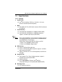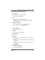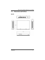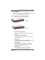
1
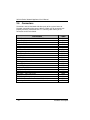
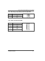
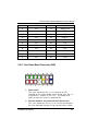
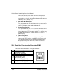
NA-320 Series Network Appliance User’s Manual Disclaimers This manual has been carefully checked and believed to contain accurate information. AXIOMTEK Co., Ltd. assumes no responsibility for any infringements of patents or any third party’s rights, and any liability arising from such use. AXIOMTEK does not warrant or assume any legal liability or responsibility for the accuracy, completeness or usefulness of any information in this document. AXIOMTEK does not make any commitment to update the information in this manual. AXIOMTEK reserves the right to change or revise this document and/or product at any time without notice. No part of this document may be reproduced, stored in a retrieval system, or transmitted, in any form or by any means, electronic, mechanical, photocopying, recording, or otherwise, without the prior written permission of AXIOMTEK Co., Ltd. Copyright 2010 AXIOMTEK Co., Ltd. All Rights Reserved July 2011, Version A2 Printed in Taiwan ii Safety Approvals CE Marking FCC Class B(NA-320/NA-320FL) 1. FCC Compliance This equipment has been tested and complies with the limits for a Class B digital device, pursuant to Part 15 of the FCC Rules. These limits are designed to provide reasonable protection against harmful interference in a residential installation. If not installed and used in accordance with proper instructions, this equipment might generate or radiate radio frequency energy and cause harmful interference to radio communications. However, there is no guarantee that interference will not occur in a particular installation. If this equipment does cause harmful interference to radio or television reception, which can be determined by turning the equipment off and on, the user is encouraged to try to correct the interference by one or more of the following measurers: Reorient or relocate the receiving antenna. Increase the separation between the equipment and receiver. Connect the equipment into an outlet on a circuit different from that to which the receiver is connected. Consult the dealer or an experienced radio/TV technician for help. Shielded interface cables must be used in order to comply with emission limits. iii Safety Precautions Before getting started, read the following important cautions. 1. Be sure to ground yourself to prevent static charge when installing the internal components. Use a grounding wrist strap and place all electronic components in any static-shielded devices. Most electronic components are sensitive to static electrical charge. 2. Disconnect the power cords from the NA-320 Series before making any installation. Be sure both the system and the external devices are turned OFF. Sudden surge of power could ruin sensitive components. Make sure the NA-320 Series is properly grounded. 3. Do not open the system’s top cover. If opening the cover for maintenance is a must, only a trained technician is allowed to do so. Integrated circuits on computer boards are sensitive to static electricity. To avoid damaging chips from electrostatic discharge, observe the following precautions: Before handling a board or integrated circuit, touch an unpainted portion of the system unit chassis for a few seconds. This will help to discharge any static electricity on your body. When handling boards and components, wear a wristgrounding strap, available from most electronic component stores. Trademarks Acknowledgments AXIOMTEK is a trademark of AXIOMTEK Co., Ltd. IBM, PC/AT, PS/2, VGA are trademarks of International Business Machines Corporation. ® ® Intel and Pentium are registered trademarks of Intel Corporation. MS-DOS, Microsoft C and QuickBASIC are trademarks of Microsoft Corporation. Other brand names and trademarks are the properties and registered brands of their respective owners. iv Table of Contents Disclaimers......................................................................... ii Safety Approvals ............................................................... iii Safety Precautions ............................................................ iv CHAPTER 1 .................................................................... 1 INTRODUCTION ............................................................ 1 1.1 1.2 1.3 1.3.1 1.3.2 1.4 1.5 1.5.1 1.5.2 1.5.3 1.5.4 General Description ........................................... 1 Features ............................................................ 2 Specifications .................................................... 3 System ........................................................................ 3 Mechanical / Environmental ........................................ 5 Dimensions and Outlines ................................... 7 I/O Outlets ......................................................... 9 Front Panel for NA-320 &NA-320FL .......................... 9 Rear Panel for NA-320 &NA-320FL ......................... 11 Front Panel for NA-320R ......................................... 13 Rear Panel for NA-320R .......................................... 15 CHAPTER 2 .................................................................. 17 HARDWARE DESCRIPTION ....................................... 17 2.1 2.2 2.3 2.4 2.4.1 2.4.2 2.4.3 2.4.4 2.4.5 2.4.6 2.5 2.5.1 2.5.2 2.5.3 2.5.4 2.5.5 Checklist .......................................................... 17 Memory Module (SODIMM) ............................. 18 Board Layout ................................................... 19 Jumper Settings .............................................. 21 Switch Button Selection Jumper (JP1 ) ..................... 22 LAN Bypass Trigger Selection Jumper (JP2, JP3) ... 23 LAN ByPass Selection Jumper (JP4) ....................... 24 TM CompactFlash Voltage Selection Jumper (JP5) .... 24 Clear CMOS Jumper (JP6) ....................................... 25 Auto Power Button Jumer (JP7) ............................... 25 Connectors ...................................................... 26 DC-In Power Jack (CN1) for NA-320 & NA-320FL ... 27 Power out Connector (CN2) ...................................... 27 LCM or SATA Power Connector (CN7) .................... 28 Mini Card Connector (CN8) ...................................... 28 Front Panel Bezel Connector (CN9) ......................... 29 v 2.5.6 2.5.7 2.5.8 2.5.9 2.5.10 2.5.11 2.5.12 2.5.13 2.5.14 2.5.15 2.5.16 2.5.17 Serial Port1 (For Console) Connector (COM1) ......... 30 Serial Port2 Connector (COM2) ................................ 31 CPU FAN Connector (FAN1) .................................... 31 System FAN Connector (FAN2) ................................ 31 PS2 Keyboard/Mouse Connector (KM1) .................. 32 Serial ATA Connector: SATA1, SATA3 ................... 32 Compact Flash™ Socket:SCF1 ............................ 33 USB Port0~Port1 Connector (USB1) ....................... 34 VGA Connector (VGA1) ........................................... 35 LED1~LED8 ............................................................. 35 USB Port2~Port3 Connector (USB2) ....................... 36 Power Input 12V Connector (ATX1) for NA-320R ... 36 CHAPTER 3 .................................................................. 37 AMI BIOS SETUP UTILITY .......................................... 37 3.1 3.2 3.3 3.4 3.5 3.6 3.7 3.8 Starting ............................................................ 37 Navigation Keys ............................................... 37 Main Menu ....................................................... 38 Advanced Menu ............................................... 39 Boot Menu ....................................................... 49 Security Menu.................................................. 52 Chipset Menu .................................................. 53 Exit Menu ........................................................ 57 APPENDIX A ................................................................ 59 ENABLING LAN BYPASS FEATURE ........................... 59 APPENDIX B ................................................................ 60 WARNING .................................................................... 60 vi NA-320 Series Network Appliance User’s Manual CHAPTER 1 INTRODUCTION This chapter contains general information and detailed specifications of the NA-320 Series Network Appliance Server. Chapter 1 contains the following sections: 1.1 General Description Features Specifications Dimensions I/O Outlets General Description The NA-320 is a 1U and desktop and NA-320R is a 1U and rackmount network security hardware platform for VPN, firewall and other ® network security applications, which consists can support of Intel ATOM D410/D510 1.66GHz FSB 667; 512K/1M L2 Cache. This platform supports the 1U desktop and 1U rack mount form factor, and the system supports DDR2 667 memory with single channel up to maximum 2 GB for one SODIMM slot. In the meantime, the platform also can support 6 Gigabit LAN ports which can provide best throughput. For the purpose to store event log data, it can deploy one 2.5” SATA2 HDD (NA-320&NA-320FL) or two 2.5” SATA2 (default) or one 3.5” SATA2 HDD (optional) in (NA-320R). This platform can be easily enabled through application programs to make a user-friendly appliance for customers, and provide the highest ever performance of encryption and decryption. Introduction 1 NA-320 Series Network Appliance User’s Manual 1.2 Features Low power and high performance for network security field ® applications. NA-320 series supports Intel ATOM D510 1.66GHz FSB 533; 512K/1M L2 Cache.(D410 for optional) Supports Six 10/100/1000Mbps Ethernet ports Supports BIOS redirected to COM port features Supports one 2.5” SATA2 Hard Disk for NA-320&NA-320FL Supports Two 2.5” SATA2 or one 3.5” SATA2 (optional) Hard Disk for NA-320R Reasonable computing performance and throughput for processor and LAN ports Suitable for Network Appliance; VPN, network bandwidth controller, firewall and UTM 2 Introduction NA-320 Series Network Appliance User’s Manual 1.3 Specifications 1.3.1 System System CPU BIOS ® Intel D510 1.66GHz FSB 533; 512K/1M L2 Cache processor onboard.(D410 for optional) AMI 16Mbit PnP Flash BIOS with function of BIOS redirected to COM port System Memory One DDR2 667 SODIMM up to 2 GB(NA-320,NA-320R) One DDR2 667 SODIMM up to 2 GB(Wide tempature support is available upon request (NA-320FL) Due to chipset limitation, system memory controller supports the following DDR2 Data Transfer Rates, SODIMM Modules and DRAM Device Technologies: DDR2 Data Transfer Rate: 667 (PC 5300), non-ECC 2 Ranks of x16 SDRAMs (Double-sided) NOTE 1 Rank of x16 SDRAMs (Single-sided) HDD Interface One 2.5” SATA2 HDD for NA-320 One 2.5” SATA2 HDD (Wide tempature support is available upon request (NA-320FL) Two 2.5” SATA2 or one 3.5” SATA2 (optional) Hard Disk for NA-320R Compact Flash One Compact Flash Type II (Wide tempature support is available upon request (NA-320FL) Network Interface ® Six 10/100/1000Mbps Ethernet (Intel 82583V) One group LAN by pass for optional(NA-320&NA-320FL) Watchdog Timer 255 stepping for porting Introduction 3 NA-320 Series Network Appliance User’s Manual USB Two USB ports in the rear side Console RS-232 Console port is the rear side(RJ-type) Power 1 x 12V, 5A power adapter for NA-320,NA-320FL AC to DC 84W open frame for NA-320R OS Compatibility 4 Redhat 2.6 Kernel Introduction NA-320 Series Network Appliance User’s Manual 1.3.2 Mechanical / Environmental Form Factor 1U Desktop for NA-320 & NA-320FL 1U Rack mount for NA-320R LED Power, HDD, Link/Act with transfer rate LAN by pass LED and promgramable LED (NA-320,NA320FL for optional) Operation Temperature 0°C ~ 40°C (32°F ~ 104°F)for NA-320&NA-320FL 0°C ~ 45°C (32°F ~ 113°F)for NA-320R Storage Temperature Humidity 10% - 95% RH, non-condensing Chassis Material -20°C ~ 70°C (-4°F ~ 158°F) Steel Dimensions 44mm (1.73”) (H) x 230mm (9.00”) (W) x 152.1mm (5.98”) (D) for NA-320 44mm (1.73”) (H) x 230mm (9.00”) (W) x 153.5mm (6.04”) (D) for NA-320FL 44mm(1.73’’)(H) x 430mm (16.93”) (W) x 248mm (9.76”) (D) for NA-320R Weight (Net/Gross) 1.295Kg / 2.295Kg (NA-320) 2.0 Kg/3.0 Kg(NA-320FL) Introduction 5 NA-320 Series Network Appliance User’s Manual 3.2Kg/4.2Kg (NA-320R) NOTE 6 All specifications and images are subject to change without notice. Introduction NA-320 Series Network Appliance User’s Manual 1.4 Dimensions and Outlines NA-320 Introduction 7 NA-320 Series Network Appliance User’s Manual NA-320FL NA-320R 8 Introduction NA-320 Series Network Appliance User’s Manual 1.5 I/O Outlets Locate the front panel I/O outlets on the NA-320 Series server to connect serial and Ethernet interface devices. 1.5.1 Front Panel for NA-320 &NA-320FL LEDs LEDs LAN By-Pass LED(for optional) While running the LAN By-Pass function, the LED always lights up. Programmable LED (for optional) A sample code will be provided that allow users to define their own function. Power LED It will be lighting when the server is powered on to perform diagnostic tests and check a proper operation. LAN Link LED It will be lighting when a twisted pair is connected to another Ethernet device on the port. It shows network transfer rate while making a connection. Activity LED It will be lighting when the server is transmitting or receiving a packet through the twisted pair ports. Introduction 9 NA-320 Series Network Appliance User’s Manual 10 HDD LED The LED flashes when transmitting or receiving any signals. Introduction NA-320 Series Network Appliance User’s Manual 1.5.2 Rear Panel for NA-320 &NA-320FL LAN Ports 12V/5A DC Power Input Reset/Default Switch USB Ports Console Port LAN Ports 12V/5A DC Power Input USB Ports Console Port Console port – RS-232 Console port is for the command of line interface and of diagnostic support by P.O.S.T (Power on Self Test). Reset Switch – It is is for reset the system to reboot your computer instead of turning OFF the power switch. It is a better way to reboot your system for a longer life of the system’s power supply.(for optional) Default Switch – The sample code will be provided that allows users to define their own function. For example, when the system has any problems, this switch can support to reset it to the customer’s OS default settings if Introduction 11 NA-320 Series Network Appliance User’s Manual our customer’s OS supports this application. (for optional) Link/Active LED (Single color)for LAN port #1, port#2, port#3, port#4, port#5, port#6 1. The orange LED is on when the LAN port connection is working. 2. The LED flashes when transmitting or receiving any signals to or from the appliance. 3. The LED is dark when the appliance is off. Transmitted LED for LAN port #1, port#2, port#3, port#4, port#5, port#6 1. The double-color LED light indicates 10/100/1000Mbps transfer rate. `Transfer Rate LED Light Color 10Mbps Dark 100Mbps Green 1000Mbps Amber 2. When the amber-color LED light is radiating, it should be 1000Mbps transfer rate at this moment. 3. When the green-color LED light is radiating, it should be 100Mbps transfer rate at this moment 4. If the LED is dark and Link/Active LED is light on or flashing, it should be 10Mbps transfer rate. 5. W hen this LED and Link/Active LED both are dark. No networking devices are attached 12 Introduction NA-320 Series Network Appliance User’s Manual 1.5.3 Front Panel for NA-320R Power/HDD/ LAN Bypass /GPIO LED Reset/Default Switch Console Port LAN Ports USB Ports Power on LED System and power on HDD LED Link/Active LED (single color) 1. The green LED is on when it is a normal HD connection. 2. The LED flashes when transmitting or receiving any signals. LAN By-Pass LED While running the LAN By-Pass function, the LED always lights up. GPIO LED A sample code will be provided that allow users to define their own function. Link/Active LED (Single color)for LAN port #1, port#2, port#3, port#4, port#5 and port#6 1. The orange LED is on when the LAN port connection is working. 2. The LED flashes when transmitting or receiving any signals to or from the appliance. 3. The LED is dark when the appliance is off. Introduction 13 NA-320 Series Network Appliance User’s Manual Transmitted LED for LAN port #1, port#2, port#3, port#4, port#5 and port#6 1. The double-color LED light indicates 10/100/1000Mbps transfer rate. `Transfer Rate LED Light Color 10Mbps Dark 100Mbps Green 1000Mbps Amber 2. When the amber-color LED light is radiating, it should be 1000Mbps transfer rate at this moment. 3. When the green-color LED light is radiating, it should be 100Mbps transfer rate at this moment 4. If the LED is dark and Link/Active LED is light on or flashing, it should be 10Mbps transfer rate. 5. W hen this LED and Link/Active LED both are dark. No networking devices are attached 14 Console port – RJ RS-232 Console port is for the command of line interface and of diagnostic support by P.O.S.T (Power on Self Test). Reset Switch – It is is for reset the system to reboot your computer instead of turning OFF the power switch. It is a better way to reboot your system for a longer life of the system’s power supply. Default Switch – The sample code will be provided that allows users to define their own function. For example, when the system has any problems, this switch can support to reset it to the customer’s OS default settings if our customer’s OS supports this application Introduction NA-320 Series Network Appliance User’s Manual 1.5.4 Rear Panel for NA-320R System Fan AC I nlet Introduction System Fan 15 NA-320 Series Network Appliance User’s Manual MEMO 16 Introduction NA-320 Series Network Appliance User’s Manual CHAPTER 2 HARDWARE DESCRIPTION The NA-320 Series are convenient for your various hardware configurations. The chapter 2 will help you get familiar with the hardware. 2.1 Checklist The package bundled with your NA-320 Series should contain the following items: The NA-320 Series network appliance hardware platform DC Power Adapter x 1,Power cord x 1(NA-320), Power cord x 1(NA-320R) Utility CD (including this User’s Manual and driver, sample code) x1 Mounting screws for disk drive and additional screws for this appliance’s spareparts Installed NA-320 cable kits (1 x S-ATA cable, 1 x SATA2 power cable, 1 x console cable) Installed NA-320R cable kits (2 x S-ATA cable, 1 x SATA2 power cable, 1 x console cable) Optional cable kits ( 1 x PS/2 KB,1x Y-type cable for KB/Mouse,1xVGA cable,1xLAN cable) Plastic stand for stack–up x 4 1U Rackmount ear it (NA-320R) If you cannot find this package or any items are missing, please contact AXIOMTEK distributors immediately. If you order any optional components, the package might contain those additional hardware or documents accordingly. Hardware Description 17 NA-320 Series Network Appliance User’s Manual 2.2 Memory Module (SODIMM) The main board supports one DDR2 667 SODIMM socket. Maximum memory capacity is up to 2GB None-ECC unbuffer memory. The following steps show you how to install the memory modules: 1 2 Push down each side of the SODIMM socket. Align the memory module with the socket that notches of memory module must match the socket keys for a correct installation. Install the memory module into the socket and push it firmly down until it is fully seated. The socket latches are levered upwards and clipped on to the edges of the DIMM. Install any remaining SODIMM modules. 3 4 18 Hardware Description NA-320 Series Network Appliance User’s Manual 2.3 Board Layout Component Side Hardware Description 19 NA-320 Series Network Appliance User’s Manual Solder Side 20 Hardware Description NA-320 Series Network Appliance User’s Manual 2.4 Jumper Settings This section provides the information about jumpers and connectors of NA-320 Series. Proper jumper settings configure the main board in this appliance to meet your application purpose. We are herewith listing a summary table of all jumpers and default settings for onboard devices, respectively. Jumper Definition JP1 TACT SW2 Selection Jumper Short (1-2) Power On/Off Short (3-4) Reset(Default) Short (5-6) GPI Short/Open JP2/JP3 JP4 LAN By-Pass Trigger 1/2 LAN By-Pass Function Function Settings Open/Short Short (1-2) Short (2-3) Open LAN5 & LAN6 Bypass Trigger 1 GPO Low Level (By Pass Enable) LAN5 & LAN6 Bypass Trigger 2 GPO High Level (By Pass Disable)(Default) LAN5 & LAN6 Bypass Always Disable LAN5 & LAN6 Bypass Always Enable LAN5 & LAN6 Bypass control by JP2 or JP3 or WDT(appendix A)(Default) Compact Flash Power Selection Short (1-2) CF Voltage Select : 3.3V(Default) Short (2-3) CF Voltage Select : 5V JP6 Clear CMOS Setting Short (1-2) Short (2-3) Normal(Default) Clear BIOS CMOS Auto Power Button Mode Selection Open Auto Power On (Default) JP7 Short Power on By Power button JP5 Hardware Description 21 NA-320 Series Network Appliance User’s Manual 2.4.1 Switch Button Selection Jumper (JP1 ) Use this jumper to select the Switch Button Function. Description Switch (SW 2) Button Selection Function Power On/Off Reset (Default) GPIO 22 Jumper Setting JP1 JP1 JP1 Hardware Description NA-320 Series Network Appliance User’s Manual 2.4.2 LAN Bypass Trigger Selection Jumper (JP2, JP3) Description LAN Bypass Trigger 1,2 Selection Function Not install Jumper Setting JP2 JP3 Low Level GPIO JP2 (By Pass Enable) JP3 High Level GPIO(Default) JP2 (By Pass Disable) JP3 NOTE If the jumper setting is “Low Level GPIO”, LAN Bypass function will still be started even when power supply is normally input. The default setting is “High Level GPIO” that LAN Bypass function is not working when power supply is normally input. Hardware Description 23 NA-320 Series Network Appliance User’s Manual 2.4.3 LAN ByPass Selection Jumper (JP4) Use this jumper to select the LAN Bypass Function. Description LAN By-Pass Function Function Jumper Setting Disabled JP4 Always By-Pass JP4 Trigger By JP2 ; JP3 or W DT (Default) JP4 2.4.4 CompactFlash TM Voltage Selection Jumper (JP5) Description Compact Flash Voltage Selection 24 Function Jumper Setting 3.3V (Default) JP5 5V JP5 Hardware Description NA-320 Series Network Appliance User’s Manual 2.4.5 Clear CMOS Jumper (JP6) You may need to use this jumper is to clear the CMOS memory if incorrect settings in the Setup Utility. Description CMOS Clear 2.4.6 Function Jumper Setting Normal (Default) JP6 Clear CMOS JP6 Auto Power Button Jumer (JP7) Description Function Auto Power Button Always Power Off; Mode Selection ATX Mode Always Power On Jumper Setting JP7 JP7 (Default) Hardware Description 25 NA-320 Series Network Appliance User’s Manual 2.5 Connectors Connectors connect the board with other parts of the system. Loose or improper connection might cause problems. Make sure all connectors are properly and firmly connected. Here is a summary table shows you all connectors on the main board. Connectors DC-In Power Jack for NA-320 & NA-320FL Power Out Connector LAN3 ~ LAN6 Connector LAN1 ~ LAN2 Connector LCM or SATA Power Connector Mini Card Connector Front Panel Bezel Connector Battery Connector Serial Port1 (For Console) Connector Serial Port2 Connector CPU FAN Connector System FAN Connector PS2 Keyboard/Mouse Connector Serial ATA Connector Serial ATA Connector Compact Flash™ Socket DDR II SO-DIMM Socket USB Port0 ~ Port1 Connector USB Port2 ~ Port3 Connector VGA Connector TACT SW1(GPI Switch) TACT SW2(Power Button; Reset or GPI Switch) Power Input +12V Connector for NA-320R 26 Label CN1 CN2 CN3 CN5 CN7 CN8 CN9 BAT1 COM1 COM2 FAN1 FAN2 KM1 SATA1 SATA3 SCF1 SDIMM1 USB1 USB2 VGA1 SW1 SW2 ATX1 Hardware Description NA-320 Series Network Appliance User’s Manual 2.5.1 DC-In Power Jack (CN1) for NA-320 & NA-320FL Pin Signal 1 +5V 2 GND 2.5.2 Power out Connector (CN2) Pin Signal 1 +12V 2 GND 3 GND 4 +5V Hardware Description 27 NA-320 Series Network Appliance User’s Manual 2.5.3 LCM or SATA Power Connector (CN7) Support 2.5” SATA HDD power or LCM module Pin Signal 1 +5V 2 RXD of COM2 3 No Connection 4 TXD of COM2 5 GND 2.5.4 Mini Card Connector (CN8) 28 Pin Signal Pin Signal 1 PCIE_WAKE- 2 +3.3V 3 N.C 4 GND 5 N.C 6 +1.5 V 7 GND 8 N.C 9 GND 10 N.C 11 PCIE_CLK- 12 N.C 13 PCIE_CLK+ 14 N.C 15 GND 16 N.C 17 N.C 18 GND 19 N.C 20 N.C 21 GND 22 PCIE_RESET- 23 N.C 24 +3.3V_SBY 25 N.C 26 GND 27 GND 28 +1.5V Hardware Description NA-320 Series Network Appliance User’s Manual 29 GND 30 SMB_CLK 31 N.C 32 SMB_DATA 33 N.C 34 GND 35 GND 36 USB_D- 37 N.C 38 USB_D+ 39 N.C 40 GND 41 N.C 42 N.C 43 N.C 44 N.C 45 N.C 46 N.C 47 N.C 48 +1.5V 49 N.C 50 GND 51 N.C 52 +3.3V 2.5.5 Front Panel Bezel Connector (CN9) 1. Power LED: : This 3-pin connector (Pin 1, 3, 5) connects a LED indicator to the system power switch on the case. Pin 1 is assigned as +, and Pin 3, Pin 5 as -. The Power LED lights up when the system is powered ON. 2. External Speaker and Internal Buzzer Connector: : This 4-pin connector (Pin 2, 4, 6, 8) can be connected to the case-mounted speaker unit or internal buzzer. W hile Hardware Description 29 NA-320 Series Network Appliance User’s Manual connecting the CPU card to an internal buzzer, please short pins 2-4; while connecting to an external speaker, you need to set pins 2-4 to Open and connect the speaker cable to pin 8 (+) and pin 2 (-). 3. ATX Power On/Off Button: : This 2-pin connector (Pin 9, 10) connects the front panel’s ATX power button to the CPU card, which allows users to control ATX power supply to be power on/off. 4. System Reset Switch: : This 2-pin connector (Pin 11, 12) can be connected to the case-mounted reset switch that reboots your computer instead of turning OFF the power switch. It is a better way to reboot your system for a longer life of the system’s power supply. 5. HDD Activity LED: : This connection is linked to hard drive activity LED on the control panel. LED flashes when HDD is being accessed. The 2-pin connector (Pin 13, 14) connects the hard disk drive to the front panel HDD LED, Pin 13 assigned as -, and Pin 14 as +. 2.5.6 Serial Port1 (For Console) Connector (COM1) The COM1 Port connector is a RJ-type connector. Pin 1 2 3 4 5 6 7 8 30 Signal Data Set Ready (DSR) Request to Send (RTS) Ground (GND) Transmit Data (TXD) Receive Data (RXD) Data Carrier Detect (DCD) Clear to Send (CTS) Data Terminal Ready (DTR) Hardware Description NA-320 Series Network Appliance User’s Manual 2.5.7 Serial Port2 Connector (COM2) Pin Signal 1 Data Carrier Detect (DCD) 2 Data Set Ready(DSR) 3 Receive Date(RXD) 4 Request to Send(RTS) 5 Transmit Data(TXD) 6 Clear to Send(CTS) 7 Data Terminal Ready 8 Ring Indicator(RI) 9 GND 10 NC 2.5.8 CPU FAN Connector (FAN1) Pin Signal 1 Ground 2 +12V 3 Rotation Detection 2.5.9 System FAN Connector (FAN2) Pin Signal 1 Ground 2 +12V 3 Rotation Detection Hardware Description 31 NA-320 Series Network Appliance User’s Manual 2.5.10 PS2 Keyboard/Mouse Connector (KM1) The board supports a keyboard and Mouse interface. Connector CN14 is for PS/2 keyboard Connection VIA “Y” Cable. Pin Signal Pin Signal 1 VCC 2 K/B Data 3 K/B CLK 4 GND 5 VCC 6 VCC 7 M/S Data 8 M/S CLK 9 GND 10 NC 2.5.11 Serial ATA Connector: SATA1, SATA3 The SATA connector is for high-speed SATA interface port and it can be connected to hard disk device. Pin Signal Pin Signal 1 GND 2 TX+ 3 TX- 4 GND 5 RX- 6 RX+ 7 GND 32 Hardware Description NA-320 Series Network Appliance User’s Manual SATA1 SATA3 2.5.12 Pin 1 3 5 7 9 11 13 15 17 19 21 23 25 27 29 31 Compact Flash™ Socket: :SCF1 Signal GND Data 4 Data 6 CS0# ATASEL Address 8 VCC Address 5 Address 3 Address 1 Data 0 Data 2 CD2# Data 11 Data 13 Data 15 Hardware Description Pin 2 4 6 8 10 12 14 16 18 20 22 24 26 28 30 32 Signal Data 3 Data 5 Data 7 Address 10 Address 9 Address 7 Address 6 Address 4 Address 2 Address 0 Data 1 IOCS16# CD1Data 12 Data 14 CS1# 33 NA-320 Series Network Appliance User’s Manual 33 35 37 39 41 43 45 47 49 VS1# IOWR# INTR CSEL# RESET# DMAREQ DASP# Data 8 Data 10 34 36 38 40 42 44 46 48 50 IORD# WE# VCC VS2# IORDY# DMAACKPDIAG# Data 9 GND 2.5.13 USB Port0~Port1 Connector (USB1) Pin Signal 1 USB_POWER 2 USB_PN0 3 USB_PP0 4 GND 5 USB_POWER 6 USB_PN1 7 USB_PP1 8 GND 34 Hardware Description NA-320 Series Network Appliance User’s Manual 2.5.14 VGA Connector (VGA1) Pin Signal Pin Signal 1 RED 2 DETECT 3 GREEN 4 NC. 5 BLUE 6 GND 7 VCC 8 DDC DATA 9 GND 10 GND 11 GND 12 Horizontal Sync 13 GND 14 Vertical Sync 15 DDC CLK 16 NC. 2.5.15 LED1~LED8 LED LED1 Signal For Lan1 Up : LINK (Green : LINK100 ; Amber : LINK1000) Down : Active (Orange) LED2 For Lan2 Up : LINK (Green : LINK100 ; Amber : LINK1000) Down : Active (Orange) LED3 For Lan3 Up : LINK (Green : LINK100 ; Amber : LINK1000) Down : Active (Orange) LED4 For Lan4 Up : LINK (Green : LINK100 ; Amber : LINK1000) Down : Active (Orange) LED5 For Lan5 Up : LINK (Green : LINK100 ; Amber : LINK1000) Down : Active (Orange) Hardware Description 35 NA-320 Series Network Appliance User’s Manual LED6 For Lan6 Up : LINK (Green : LINK100 ; Amber : LINK1000) Down : Active (Orange) LED7 Up : Power LED (Green) Down : GPIO (Programmable LED; Option) LED8 Up : HDD LED (Green) Down : Lan Bypass LED (Option) 2.5.16 USB Port2~Port3 Connector (USB2) The Universal Serial Bus (USB) connector on the board is for the installation of peripherals supporting the USB interface. USB2 is a 10-pin standard onboard USB connectors. Pin Signal Pin Signal 1 USB_ POWER 2 USB _POWER 3 USB _PN2 4 USB _PN3 5 USB _PP2 6 USB _PP3 7 GND 8 GND 9 GND 10 GND USB2 2.5.17 Power Input 12V Connector (ATX1) for NA-320R To connect with the 12V power supply . 36 Pin Signal 1 GND 2 GND 3 +12V 4 +12V Hardware Description NA-320 Series Network Appliance User’s Manual CHAPTER 3 AMI BIOS SETUP UTILITY This chapter provides users with detailed description how to set up basic system configuration through the AMIBIOS8 BIOS setup utility. 3.1 Starting To enter the setup screens, follow the steps below: 1. 2. Turn on the computer and press the <Del> key immediately. After you press the <Delete> key, the main BIOS setup menu displays. You can access the other setup screens from the main BIOS setup menu, such as the Chipset and Power menus. 3.2 Navigation Keys The BIOS setup/utility uses a key-based navigation system called hot keys. Most of the BIOS setup utility hot keys can be used at any time during the setup navigation process. These keys include <F1>, <F10>, <Enter>, <ESC>, <Arrow> keys, and so on. Note Some of navigation keys differ from one screen to another. Left/Right The Left and Right <Arrow> keys allow you to select a setup screen. Up/Down The Up and Down <Arrow> keys allow you to select a setup screen or sub-screen. +− − Plus/Minus The Plus and Minus <Arrow> keys allow you to change the field value of a particular setup item. Tab The <Tab> key allows you to select setup fields. F1 The <F1> key allows you to display the General Help screen. AMI BIOS Setup Utility 37 NA-320 Series Network Appliance User’s Manual F10 The <F10> key allows you to save any changes you have made and exit Setup. Press the <F10> key to save your changes. Esc The <Esc> key allows you to discard any changes you have made and exit the Setup. Press the <Esc> key to exit the setup without saving your changes. Enter The <Enter> key allows you to display or change the setup option listed for a particular setup item. The <Enter> key can also allow you to display the setup sub- screens. 3.3 Main Menu When you first enter the Setup Utility, you will enter the Main setup screen. You can always return to the Main setup screen by selecting the Main tab. There are two Main Setup options. They are described in this section. The Main BIOS Setup screen is shown below. 38 AMI BIOS Setup Utility NA-320 Series Network Appliance User’s Manual System Time/Date Use this option to change the system time and date. Highlight System Time or System Date using the <Arrow> keys. Enter new values through the keyboard. Press the <Tab> key or the <Arrow> keys to move between fields. The date must be entered in MM/DD/YY format. The time is entered in HH:MM:SS format. 3.4 Advanced Menu The Advanced menu allows users to set configuration of the CPU and other system devices. You can select any of the items in the left frame of the screen to go to the sub menus: CPU Configuration IDE Configuration Hardware Health Configuration ACPI Configuration APM Configuration MPS Configuration Remote Access Configuration USB Configuration For items marked with “”, please press <Enter> for more options. AMI BIOS Setup Utility 39 NA-320 Series Network Appliance User’s Manual CPU Configuration This screen shows the CPU Configuration, and you can change the value of the selected option. IDE Configuration You can use this screen to select options for the IDE Configuration, and change the value of the selected option. A description of the selected item appears on the right side of the screen. For items marked with “”, please press <Enter> for more options. 40 AMI BIOS Setup Utility NA-320 Series Network Appliance User’s Manual ATA/IDE Configuration Use this item to specify the integrated IDE controller. There are three options for your selection: Disable, Compatible and Enhanced. Legacy IDE Channels When the ATA/IDE Configuration is set to Compatible, this item will be displayed. Primary/Secondary/Third/IDE Master/Slave Select one of the hard disk drives to configure IDE devices installed in the system by pressing <Enter> for more options. Super IO Configuration You can use this screen to select options for the Super IO Configuration, and change the value of the selected option. A description of the selected item appears on the right side of the screen. AMI BIOS Setup Utility 41 NA-320 Series Network Appliance User’s Manual Serial Port1 Address This option specifies the base I/O port address and Default setting is 3F8. Here are the options for your selection, Disabled. Serial Port2 Address This option specifies the base I/O port address and Default setting is 2F8. Here are the options for your selection, Disabled. Hardware Health Configuration This screen shows the Hardware Health Configuration, and a description of the selected item appears on the right side of the screen 42 AMI BIOS Setup Utility NA-320 Series Network Appliance User’s Manual System Temperature Show you the current system temperature. CPU Temperature These read-only fields show the functions of the hardware thermal sensor by CPU thermal diode that monitors the chip blocks to ensure a stable system. Vcore 12V / 5V / 3.3V Show you the voltage of 12V / 5V / 3.3V and etc. ACPI Settings You can use this screen to select options for the ACPI Settings, and change the value of the selected option. A description of the selected item appears on the right side of the screen. AMI BIOS Setup Utility 43 NA-320 Series Network Appliance User’s Manual 44 AMI BIOS Setup Utility NA-320 Series Network Appliance User’s Manual General ACPI Configuration Scroll to this item and press <Enter> to view the General ACPI Configuration sub menu, which contains General ACPI (Advanced Configuration and Power Management Interface) options for your configuration. Suspend mode After the selected period of system inactivity (1 minute to 1 hour), all devices except the CPU shut off. The default value is “S1”. Disabled System will never enter SUSPEND mode 1/2/4/6/8/1 0/20/30/40 Defines the continuous idle time before the system entering SUSPEND mode. If any item defined in (J) is enabled & active, SUSPEND timer will be reloaded. Min/1 Hr AMI BIOS Setup Utility 45 NA-320 Series Network Appliance User’s Manual Advanced ACPI Configuration Scroll to this item and press <Enter> to view the Advanced ACPI Configuration sub menu, which contains Advanced ACPI (Advanced Configuration and Power Management Interface) options for your configuration. ACPI Version Features This item shows ACPI’s version. ACPI APIC support Use this item to enable or disable APIC (Advanced Programmable Interrupt Controller) mode that provides symmetric multi-processing (SMP) for systems. Remote Access 46 AMI BIOS Setup Utility NA-320 Series Network Appliance User’s Manual Serial port number This item specifies the base I/O port address and Interrupt Request address of serial port 1. The Optimal setting is 3F8/IRQ4. Serial Port Mode This item allows you to setup the data transfer rate for the console port. The default value is 115200. Available options are “9600”, “19200”, “38400”, “57600” and “115200”. Flow Control This item allows you to select flow control for console redirection. The configuration options: None, Hardware and Software. Redirection After BIOS POST Use this item to enable or disable the function of Console Redirection, which allows you maintain a system from a remote location. The default setting is Always. Therminal Type This item allows you to select the target therminal type. AMI BIOS Setup Utility 47 NA-320 Series Network Appliance User’s Manual Configuration options: ANSI, VT100 and VT-UTF8. 48 VT-UTF8 Combo Key Support Use this item to “Enabled” or “Disabled” VT-UTF8 combination key supports for ANSI / VT100 therminals. Sredir Memory Display Delay This item allows you to indicate the length of time in seconds to off the memory display delay. The default setting is “No delay”. AMI BIOS Setup Utility NA-320 Series Network Appliance User’s Manual 3.5 Boot Menu The Boot menu allows users to change boot options of the system. You can select any of the items in the left frame of the screen to go to the sub menus: For items marked with “”, please press <Enter> for more options. Boot Setting Configuration AMI BIOS Setup Utility 49 NA-320 Series Network Appliance User’s Manual 50 Quick Boot Enabling this item lets the BIOS skip some power on self tests (POST). The default setting is Enabled. AddOn ROM Display Mode This item selects the display mode for option ROM. The default setting is Force BIOS. Boot Num-Lock Use this item to select the power-on state for the NumLock. The default setting is On. PS/2 Mouse Support This item determines if the BIOS should reserve IRQ12 for the PS/2 mouse or allow other devices to make use of this IRQ. Here are the options for your selection, Auto, Enabled and Disabled. Wait For ‘F1’ Of Error If this item is enabled, the system waits for the F1 key to be AMI BIOS Setup Utility NA-320 Series Network Appliance User’s Manual pressed when error occurs. The default setting is Enabled. Hit ‘DEL’ Message Display If this item is enabled, the system displays the message “Press DEL to run Setup” during POST. The default setting is Enabled. LAN Boot Configuration This item allows you to select the value of the LAN boot function. AMI BIOS Setup Utility 51 NA-320 Series Network Appliance User’s Manual 3.6 Security Menu The Security menu allows users to change the security settings for the system. 52 Supervisor Password This item indicates whether a supervisor password has been set. If the password has been installed, Installed displays. If not, Not Installed displays. User Password This item indicates whether a user password has been set. If the password has been installed, Installed displays. If not, Not Installed displays. Change Supervisor Password Select and press <Enter> to access the sub menu. You can use the sub menu to change the supervisor password. Change User Password Select and press <Enter> to access the sub menu. You can use the sub menu to change the user password. AMI BIOS Setup Utility NA-320 Series Network Appliance User’s Manual 3.7 Chipset Menu The Chipset menu allows users to change the advanced chipset settings. You can select any of the items in the left frame of the screen to go to the sub menus: North Bridge Configuration South Bridge Configuration For items marked with “”, please press <Enter> for more options. North Bridge Configuration You can press <Enter> for more options about your North Bridge configuration. AMI BIOS Setup Utility 53 NA-320 Series Network Appliance User’s Manual Video Function Configuration This item is for setting up the video function. 54 AMI BIOS Setup Utility NA-320 Series Network Appliance User’s Manual DVMT Mode Select DVMT (Dynamic Video Memory Technology) helps you select the video mode. South Bridge Configuration AMI BIOS Setup Utility 55 NA-320 Series Network Appliance User’s Manual 56 WDTO Trigger The selections for this item are “HW Reset” / “LAN by pass”. If the system hardware has LAN by pass specification, this item could be choosed to enable for LAN by pass control. AMI BIOS Setup Utility NA-320 Series Network Appliance User’s Manual 3.8 Exit Menu The Exit menu allows users to load your system configuration with optimal or failsafe default values. Save Changes and Exit When you have completed the system configuration changes, select this option to leave Setup and reboot the computer so the new system configuration parameters can take effect. Select Save Changes and Exit from the Exit menu and press <Enter>. Select Ok to save changes and exit. Discard Changes and Exit Select this option to quit Setup without making any permanent changes to the system configuration. Select Discard Changes and Exit from the Exit menu and press <Enter>. Select Ok to discard changes and exit. AMI BIOS Setup Utility 57 NA-320 Series Network Appliance User’s Manual 58 Discard Changes Use this item to abandon all changes. Load Optimal Defaults It automatically sets all Setup options to a complete set of default settings when you select this option. The Optimal settings are designed for maximum system performance, but may not work best for all computer applications. In particular, do not use the Optimal Setup options if your computer is experiencing system configuration problems. Select Load Optimal Defaults from the Exit menu and press <Enter>. Load Fail-Safe Defaults It automatically sets all Setup options to a complete set of default settings when you select this option. The Fail-Safe settings are designed for maximum system stability, but not maximum performance. Select the Fail-Safe Setup options if your computer is experiencing system configuration problems. Select Load Fail-Safe Defaults from the Exit menu and press <Enter>. Select Ok to load Fail-Safe defaults. AMI BIOS Setup Utility NA-320 Series Network Appliance User’s Manual APPENDIX A ENABLING LAN BYPASS FEATURE What is the LAN by-pass meant for NA-320 Series? It doesn’t have any down time in network connections for two other network segments (LAN1 and LAN2) when any fetal errors occur to this device. The LAN by-pass feature covers three levels as below: 1. Power loss While the AC power loss occurs to this device, the LAN1 and LAN2 still can communicate with each other through hardware relay like as a short cut between two segments. If the power inlet can be normally done, the relay will turn to another correct position. 2. GPIO control It acts like a switch of the application software. You can enable the hardware relay feature through the GPIO control through the application programs. Then, the software solution provider can be more flexible to make it close with the program. 3. WDT (Watchdog Timer) The hardware supports the WDT (Watchdog Timer) function. While time-out happens after a defaulted period, the WDT will reset the system or make a short cut for two specific segments by hardware relay. Note: Please refer to BIOS “WDT function selection”. The sample codes for the above features can be found in the CD, and they are only for customers’ reference as remarked. Appendix 59 NA-320 Series Network Appliance User’s Manual APPENDIX B WARNING This is a class B Product. In a domestic Environment this Product may cause radio interference in which case the user may be required to take adequate measures. It will be danger if battery is incorrectly replaced. Replacing only with the same or equivalent type is highly recommended by the manufacturer. Dispose of used batteries according to the manufacturer’s instructions. Warning for Hard Disk Drive Selection: TUV approved Hard Disk Drive is preferred for TUV compliance Hard Disk drive-Optional, (NW GQ2), generic, Input Voltage rated 5V dc/1.0A, 12V dc/1.8A maximum. Minimum clearance from uninsulated live parts 4.0 mm. “The equipment is to be installed in an environment with maximum ambient temperature must not exceed 45°° C.” “The openings on the enclosure are for air convection hence protected the equipment from overheating. DO NOT COVER THE OPENINGS.” 60 Appendix NA-320 Series Network Appliance User’s Manual “Lay this equipment on a reliable surface when install. A drop or fall could cause injury.” “The equipment shall be installed according to specification as nameplate. Make sure the voltage of the power source when connect the equipment to the power outlet. The current of load and output power of loads shall be not over the specification.”“This equipment must be connected to the reliable earthling before using.” Electric shock hazard inside the redundant power supply The exchange of modules shall be done by service person. Appendix 61