1
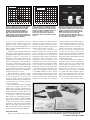
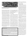
Note: The following is a Product Review from QST that is
normally available only on the ARRL MembersOnly page (along with
all Product Reviews from 1980 to the present!) ARRL membership
offers valuable benefits to new and experienced amateurs alike.
PRODUCT REVIEW
Elecraft K2 HF Transceiver Kit
Reviewed by Larry Wolfgang, WR1B
Senior Assistant Technical Editor
Okay, let’s start out with a show of hands.
How many of you have built a Heathkit?
That’s what I thought. Practically everyone
who has been a ham for more than 20 years
has assembled at least one of those
classics—and the rest of you have had to
listen to us reminisce about it. With detailed
step-by-step instructions, you didn’t have to
be an engineer or even a practiced technician
to successfully complete a Heathkit.
As an ever-increasing number of
features were added to commercially built
electronic equipment, and as the circuitry
became more miniaturized and complex, it
became harder and harder for Heathkit
home-built products to compete with the
automated assembly lines of the big
electronics manufacturers. With diminishing cost savings, and a growing level of
compromise in features, fewer and fewer
people were building Heathkits.
I wish I had a nickel for every time I’ve
heard someone lament that “No one can
build their own gear anymore.” A lot of
hams are missing out on the fun of building
in spite of the number of reliable mail-order
parts suppliers and the numerous small
companies that currently offer kits.
No More Whining
Are you one of those who mourn the
demise of Heath’s Amateur Radio products
line—or have you just been looking for that
next suitable construction project? No
matter. Roll up your sleeves and warm up
your soldering irons, because Elecraft
(that’s pronounced like a combination of
“elegant craft”) has eliminated your reason
for complaining.
With the first prototype shown at the
Dayton Hamvention in 1998, the Elecraft
K2 has been under development for several
years. Wayne Burdick, N6KR, has designed
several kit radios for the Northern
California QRP Club over the years. In fact,
Bob Dyer, KD6VIO, formed Wilderness
Radio to distribute several of Wayne’s kits.
(The NORCAL/Wilderness Sierra project
has been described in The ARRL Handbook
for several years.) So when Wayne Burdick
and Eric Swartz, WA6HHQ, teamed up to
form Elecraft, everyone knew the result
would be a fine radio!
The QRP community has always been a
hotbed of activity for building and
modifying gear. QRP operators work plenty
of DX, operate contests and generally have
fun ragchewing with other hams. Whether
they choose 5 W or less than 1 W, these
hams still find plenty of contacts and have
tons of fun! While the K2 is not “just” a
QRP transceiver, its roots are clearly there.
When the basic Elecraft K2 kit is
completed, the result is a well-appointed
CW transceiver that covers 80 through 10
meters and provides an adjustable power
output level that ranges from hard-core
QRPp levels up to about 12 W. A memory
keyer is even included! You can add an
optional SSB adapter, a 160-meter module,
a two-stage noise blanker, and/or an
automatic antenna tuner for even more
radio. Install the internal 2.9 Ah battery
option and grab an antenna, key and/or
microphone and you’ll have a very
compact, portable, self-contained system
that is ready to go almost anywhere.
Elecraft plans to eventually offer an RF
amplifier option for those who just have to
have more power. A computer interface
option is also on the way. Other options that
are currently “in the works” include an
Antenna Switch/SWR Bridge, an Audio
BOTTOM LINE
The Elecraft K2 represents a remarkable
advance in the level of sophistication and
performance available in a build-it-yourself
format. While assembly will require some
proficiency with basic electronics assembly
techniques, with Internet access, valuable
assistance can be as close as your keyboard.
Joe Bottiglieri, AA1GW
t
Filter for CW and a Transverter Interface.
No telling what else might transpire when
Wayne and Eric put their heads together.
Building a Kit Radio
Let’s start out with some kit building
basics. ALWAYS follow the directions.
Take an inventory of the parts before you
start stuffing the circuit boards. This will
help you become familiar with everything
in the kit and will make it easier to locate
any special hardware or components during
the assembly process. This will also allow
you to spot any missing parts, so that you
can contact the manufacturer for replacements before you reach that step in the
assembly process.
I spent nearly three hours inventorying
this kit. There were no missing pieces.
You will need a clean, well-lit work area,
a grounded, temperature-controlled
soldering iron and a few basic tools—such
as needle-nose pliers, close trimming wire
cutters and an assortment of screwdrivers.
An antistatic mat or grounded wrist strap is
important for safe handling of staticsensitive transistors and ICs. Elecraft
suggests that you use Kester 2% silver solder
to build your kit. The solder is not included.
A digital multimeter is always a handy
piece of basic test equipment. If your meter
also measures capacitance, so much the
better. This can be very useful for verifying
component values before installation. Of
course, the more and better your complement of test equipment, the easier it will
be to align and—if necessary—troubleshoot the radio later, but a fully equipped
test bench is not a requirement. In fact,
during the course of the assembly, the
Assistant Technical Editor
From March 2000 QST © ARRL
Table 1
Elecraft K2, serial number 00495
Manufacturer’s Claimed Specifications
Measured in the ARRL Lab
Frequency coverage: Receive and transmit, 3.5-4; 7-7.3;
Receive, 2.9-4.1, 6.5-7.3, 10-10.5, 13.2-14.7, 17.1-22;
10-10.2; 14-14.5; 18-18.2; 21-21.6; 24.8-25; 28-28.8 MHz. 1, 2
23.2-30.4 MHz; transmit, as specified.
Modes of operation: USB, LSB, CW.
As specified.
Power requirement: 8.5-15 V dc, receive, 0.25 A
Receive, 0.3 A (maximum volume, no signal);3
(no signal); transmit, 2.0 A, at 13.8 V.
transmit, 2.5 A (maximum), tested at 13.8 V.
Size (hwd): 3.4×7.9×9.9 inches; weight, 3.3 lb. With optional internal battery, 5.75 lb.
Receiver
SSB/CW sensitivity: preamp off, –130 dBm;
preamp on, –135 dBm.
Blocking dynamic range: preamp off, 133 dB;
preamp on, 125 dB.
Two-tone, third-order IMD dynamic range:
preamp off, 96 dB; preamp on, 97 dB.
Third-order input intercept point: Not specified.
Second-order intercept point: preamp off and on, +70 dBm.
S-meter sensitivity: Not specified.
Receiver audio output: 2 W into 4 Ω, THD not specified.
IF/audio response: Not specified.
IF rejection: Not specified.
Image rejection: Not specified.
Transmitter
Power output: SSB, CW, 0.1-10 W.
Spurious-signal and harmonic suppression: 40 dB.
SSB carrier suppression: 40 dB or greater.
Undesired sideband suppression: Not specified.
Third-order intermodulation distortion (IMD) products:
CW keyer speed range: 9 to 50 WPM.
CW keying characteristics: Not specified.
Transmit-receive turnaround time (PTT release to
50% audio output): Not specified.
Receive-transmit turnaround time (“tx delay”):
Not specified.
Composite transmitted noise: Not specified
Receiver Dynamic Testing
Noise floor (MDS), 700 Hz filter:4
Preamp off
Preamp on
3.5 MHz
–133 dBm
–137 dBm
14 MHz
–131 dBm
–138 dBm
Blocking dynamic range (700-Hz IF filter):
Preamp off
Preamp on
3.5 MHz
136 dB
127 dB
14 MHz
136 dB
128 dB
Two-tone, third-order IMD dynamic range (700-Hz IF filter):
Preamp off
Preamp on
3.5 MHz
100 dB
95 dB
14 MHz
97 dB
98 dB
Preamp off
Preamp on
3.5 MHz
+20.9 dBm
+5.1 dBm
14 MHz
+21.6 dBm
+6.9 dBm
14 MHz, preamp off, +75 dBm; preamp on, +76 dBm.
S9 signal at 14 MHz: preamp off, 115 µV; preamp on, 19 µV.
2 W at 0.6% THD into 4 Ω.
Range at –6 dB points, (bandwidth):5
CW-N: 625-1000 Hz (375 Hz)
CW-W: 211-1471 Hz (1260 Hz)
USB: 370-2222 Hz (1852 Hz)
LSB: 526-2000 Hz (1474 Hz)
Preamp off, 89 dB.
Preamp off, 74 dB.
Transmitter Dynamic Testing
SSB, typically 1-10 W; CW, typically 0.1-12 W.
44 dB. Meets FCC requirements for spectral purity.
51 dB.
>56 dB.
See Figure 1.
9 to 41 WPM.
See Figure 3.
S9 signal, 35 ms. Unit is suitable for use on AMTOR.
SSB, 23 ms.
See Figure 2.
All dynamic range measurements are taken at the ARRL Lab standard spacing of 20 kHz.
1 Plus 1.8-2 MHz with 160-meter option.
2 Receive range extends beyond the transmit range but performance there is not specified.
3 Special settings for battery-powered operation can be engaged that reduce the receive current requirement to 153 mA.
4 Refer to the IF/audio response data for the actual filter bandwidth.
5 Filter passband ranges are adjustable (see text).
partially built K2 acts as a voltmeter,
ammeter, frequency counter and wattmeter!
Let’s Get Started
The K2 arrives neatly packed inside a
small cardboard box. Inside you will find
plastic bags labeled with the corresponding
circuit board names: “Control,” “Front
Panel,” “RF” and one bag with assorted
hardware labeled “Misc.” None of the
From March 2000 QST © ARRL
components are surface-mount. The cabinet
panels, display, speaker and main tuning
knob are wrapped in kraft paper to protect
them from scratches or other damage.
The Owner ’s Manual is a 162-page
spiral-bound document. The detailed
assembly and alignment instructions are
definitely reminiscent of the legendary Heath
manuals. There is currently a short list of
manual errata, with clear instructions about
the required changes in the text. A separate
sheet lists a few important precautions.
Some builders have reported completing
their basic K2s in about 35 hours—I prefer
to work at a more relaxed pace. If you
simply stuff components on the boards and
solder them in, you will learn little about
the circuit and even less about electronics.
By locating the components on the
schematic diagram and tracing the circuit
0
–60
Reference Level: 0 dB PEP
–10
–70
–20
–80
–30
–90
–40
–100
–50
–110
–60
–120
–70
–130
–80
–10
–8
–6
–4
–2
0
2
4
Frequency Offset (kHz)
6
8
10
–140
2
Reference Level: - 60 dBc/Hz
Vertical Scale: dBc/Hz
4
6
8
10
12
14
16
18
20
Frequency Sweep: 2 to 22 kHz from Carrier
22
Figure 1—Worst-case spectral display of
the Elecraft K2 transmitter during twotone intermodulation distortion (IMD)
testing. The worst-case third-order
product is approximately 29 dB below
PEP output, and the worst-case fifthorder product is down approximately 44
dB. The transmitter was being operated at
10 W PEP output at 28.350 MHz.
Figure 2—Worst-case spectral display
of the Elecraft K2 transmitter output
during composite-noise testing. Power
output is 10 W at 3.52 MHz. The carrier,
off the left edge of the plot, is not
shown. This plot shows composite
transmitted noise 2 to 22 kHz from the
carrier.
Figure 3—CW Keying waveform for the
Elecraft K2 showing the first two dits in
full-break-in (QSK) mode using external
keying. Equivalent keying speed is 60
WPM. The upper trace is the actual key
closure; the lower trace is the RF
envelope. Horizontal divisions are 10
ms. The transceiver was being operated
at 10 W output at 14.2 MHz.
as you go, you can actually begin to
understand how all these pieces come
together to make a radio. Altogether, we
spent close to 60 hours building the review
radio, including the SSB adapter and noise
blanker options.
Assembly begins with the control board
and the front panel (display) board. A
photograph of the completed control board
appears in Figure 5. Once these are
finished, you are instructed to add a few
components to the main board—the RF
board—and then take some preliminary
resistance measurements. Some of the
enclosure panels are assembled and the RF
board is temporarily installed. The display
board and the front panel board are then
plugged into the RF board in preparation
for some initial power-on tests.
Wait. Did that say “plug in” these
boards? Yes, that’s right. There are virtually
no wiring harnesses or point-to-point
wiring in the K2. All the connections
between the subassembly circuit boards are
accomplished with mating multipin
connectors. Elegant!
Once I had reached this point I plugged
in the power supply cable and—with
fingers firmly crossed—pushed the ON
button. ELECrAFt popped up in the display,
shortly followed by 7100.0! Success! It
worked. Now to run through the first round
of alignments… But wait. The buttons
didn’t seem to be responding properly. I
pressed a few buttons, held the LOCK
button, then pressed it again to return to
normal VFO operation. Now everything
seemed fine—but there must be something
that’s not quite right. Now what? It was 10
PM, and I wanted to work on it a bit longer.
I sure couldn’t call Elecraft at that hour…
“lifelines.” There’s a K2 e-mail reflector
with lots of other builders on line. I
wondered if anyone else had run into this
problem. I fired off a quick message to the
reflector and waited for a response.
I received a quick reply from Tom
Hammond, N0SS. Tom is one of the “Field
Testers” who built one of the first 100 K2
kits and provided lots of feedback and
suggestions to Wayne and Eric. Tom told me
to check the solder connections on the
pushbuttons. A few other replies came in
from builders who hadn’t run into this type
of problem, but they encouraged me to make
a more thorough visual inspection. It was
getting late; I closed up shop for the night.
The following day I decided to give
Wayne a call. He helped me narrow it down
to the A=B and RIT switches. Wayne
explained that two of the switch posts feed
a signal through from one portion of the
circuit board to another, and he believed
that that was the source of my problem.
After reheating the posts and flowing on a
bit more solder, the problem was solved.
It is certainly possible to build a K2
without Internet access, but there is a
wealth of information available there. In
fact, this may be one of Elecraft’s most
valuable assets. Many questions are
answered by individuals who encountered
similar problems. In addition, there are
discussions about circuit modifications and
updates from Elecraft.
The technical support from Elecraft is
excellent. Wayne and Eric monitor the
reflector, and if they see a question that
wasn’t answered satisfactorily they will
soon fire off a note with the corrections or
clarifications. Of course for real tough
problems, e-mail sent directly to Elecraft
or a phone call to their technical support
line is sure to get you the help you need.
What other manufacturer lets you communicate directly with the design team?
Just monitoring the reflector can be
Enter the Internet
Regis—I’ve decided to use one of my
Figure 4—The three main circuit boards and their corresponding parts bags. At this
stage I had completed the control board and was working on the display board.
From March 2000 QST © ARRL
two inductors. Don’t let this happen to you!
Be careful to identify the correct location
for every part before you install it, and
recheck before soldering.
Alignment and Testing
Figure 5—A closer look at the completed control board. The glass epoxy boards
have plated through holes and the component identifications and locations are
clearly silk-screened on the boards.
quite informative. Someone mentioned that
they really missed not having a dimple on
the main tuning knob. Someone else noticed
that the knob on their Yaesu FT-100 was
about the same size. Subsequent postings
indicated that the parts sales staff at Yaesu
quickly learned that all these knobs were
being ordered for Elecraft K2 radios—not
Yaesu FT-100s. Within two days they had
sold out their entire stock of replacements!
In another posting, a European builder
circulated a question regarding degraded
receiver performance after installing the
noise blanker option. After several
questions about measurements and hearing
from a few others who had noticed a similar
effect, Wayne and Eric went to work
tracking down the problem. Their response?
A change in the design of the noise blanker
and an upgrade kit for the earlier version.
The optional noise blanker that we
received with our initial K2 shipment
several months ago was the “original”
version. With it installed, our lab tests
revealed reduced intermodulation distortion
dynamic range and blocking dynamic range
and a degraded third-order intercept
point—even with the noise blanker
deactivated. Elecraft provided us with the
upgrade. Table 1 reflects the performance
that we measured with the latest version of
the noise blanker installed.
If you have Internet access, once you’ve
ordered your kit, I highly recommend that
you subscribe to the reflector. Send an email to [email protected] with
subscribe elecraft in the body of the
message. You can also view the list archives
at http://www.elecraft.com.
Back to Building
After completing the first-stage
alignment and testing, the boards are
removed from the partially completed
enclosure and the remainder of the
components are installed on the RF board.
Most of your efforts will be in assembling
the receiver section. Here you will wind
your first toroidal inductors and
transformers. The K2 contains a total of 14
toroidal inductors and six toroidal
transformers. In addition, there is one
transformer wound on a binocular core.
Because time was running short to
complete this review for this special QRP
issue, once I’d finished up the receiver
section, I turned the kit over to Zack Lau,
W1VT, for completion of the transmitter
section and the final alignment. Zack
reported no major difficulties, except that
I had installed RFC3 in L16’s spot and vice
versa. This caused some problems with the
receiver on 40 and 80 meters. Once Zack
located and corrected my error, everything
was fine. In my defense, the label for RFC3
is directly between the locations for these
How Did It Do in the Lab?
The technical performance of radios comes out during lab testing. Usually, the transmit IMD
and receiver dynamic range results separate the toys from the big boys. Usually!
On SSB, this radio is clean. As seen in Figure 1, the high-order intermodulation products
are quite good. The CW keying is nice, too, as shown in Figure 3. No key clicks from this baby!
But where the K2 really shines is in its receiver performance. On average, transceivers
positioned in the upper tiers of the popular HF product lines (in the $2000 to $3500 price class)
exhibit blocking dynamic range measurements somewhere in the vicinity of 130 dB and a twotone, third-order dynamic range near 95 dB. The K2’s receiver performance compares very
favorably to that of the samples of the high-end radios we’ve recently examined, turning in
impressive 136/97 dB figures for these parameters.
The fact that a radio in this price class—and a home-built one at that—can stand proudly
in such company is a remarkable accomplishment. This is the first-generation radio that Elecraft
has produced. I can’t wait to see the next one!— Ed Hare, W1RFI/QRP, ARRL Laboratory
Supervisor
From March 2000 QST © ARRL
The alignment steps involve adjusting a
few tuned inductors and variable capacitors
to set the voltage controlled oscillator and
the various tuned circuits. The control
software performs a procedure to linearize
the VFO operation across the tuning range.
You also adjust the crystal filter settings and
the BFO settings for each mode and band.
The filter scheme is especially interesting. Most commercial transceivers come
with a “stock” filter for sideband and a
narrower filter for CW operation. In
addition to these there is usually room to
add one or two additional optional filters.
The K2 uses a scheme of diode switching
and software control to provide four crystal
filter settings for each mode. These are adjustable, so you can tailor the bandwidths
to suit your operating style. The factory
default settings for CW are 1.5 kHz and
700, 400 and 100 Hz.
You also set up four filter bandwidths
for SSB reception. The defaults are 2.2, 2.0,
1.8 and 1.6 kHz. (You can still receive SSB,
RTTY and the data modes even with a basic
“CW Only” K2).
If you should decide to add the SSB
adapter, there is yet another filter—
optimized for SSB operation at about
2.3 kHz. In that case, filter 1 is optimized
for SSB transmit and filter 2 is optimized
for SSB receive. Filter 3 can be set as a
narrow bandwidth SSB filter. The default
is 1.6 kHz. Filter 4 can even be set at a
narrower bandwidth—useful for the data
modes.
Some builders have reported confusion
about the procedures for aligning the filters
and BFO settings. When we followed the
steps in the Owner’s Manual we came close,
but the settings were not “perfect.” There
have been several discussions about this on
the e-mail reflector, including postings
about programs to download that will allow
you to use your computer’s sound card as
an audio spectrum analyzer. Elecraft has
indicated that they will be changing some
of the procedures in the manual.
The K2’s control software includes
extensive diagnostics. If you turn on the
radio and the display shows “LOW BATT,”
the software is telling you that the battery
or power supply voltage is too low, a
display of “HI-CUR” on transmit indicates
that the user-programmable current level
was exceeded, and so on. Troubleshooting
charts are provided. This could be especially helpful if you run into difficulties
getting the radio working initially.
switched in.) This filter is optimized for
narrow bandwidths of about 200 to 500 Hz,
but it can be adjusted wider or narrower if
desired. A second two-pole crystal filter
follows the IF amplifier. This filter can also
be tuned, but over a smaller bandwidth
range. The AGC signal is derived from the
IF amp output using an auxiliary low
frequency IF of about 150 kHz.
The Finished Product
Figure 6—An internal view with the top cover removed. The display and control
board plug into the RF board along its front edge. Note the almost total absence
of point-to-point wiring. The rear apron is pre-punched for a wide variety of
available and proposed optional accessories.
A Few Circuit Details
The K2 uses a modular design that
allows flexibility and opportunities for
future expansion. The display board
provides the user interface, including the
display and all the controls. The control
board contains the main microprocessor, the
dc control signal circuits, the AGC circuit
and the audio amplifier. The RF board
serves as a “motherboard” for these two
boards and any optional boards. In addition
to all the RF circuitry, this board contains
the I/O controller and the latching relays
that select the operating band.
The receiver is a single-conversion
superheterodyne that employs double-tuned
band-pass filters for each band. It uses a
down-conversion scheme with an IF of
4.915 MHz. The individual band-pass
filters provide superior IMD performance
when compared to up-converting designs
that often use a single low-pass filter to
remove image products. Because the BFO
is microprocessor controlled, its frequency
is reset for USB and LSB reception as well
as CW on either side of the carrier.
In transmit, the signal flow reverses,
with the output signal going through the
band-pass and low-pass filters. The RF
amplifier can produce over 10 W and is
designed to provide good immunity to high
SWR. PIN-diode T-R switching results in
silent QSK operation.
The microprocessor firmware controls
just about every aspect of the K2’s
operation. There are many routines that run
behind the scenes. For example, the PLL
reference oscillator is linearized on each
band by an auto-calibration routine. The
results of this routine are stored in
EEPROM tables for use each time you turn
on the radio. The firmware also supports
features like built-in test equipment, a
memory keyer, dual VFOs with split
operation and frequency and band stacking
memories. Provisions are included for a
variety of optional modules, such as the
SSB adapter, the noise blanker, the
automatic antenna tuner and so on. With
just 8 kilobytes of memory in the PIC
16C77 microcontroller, it’s readily apparent
that the control program code has been
highly optimized!
The I/O controller is a coprocessor IC.
The SSB adapter board carries its own coprocessor, as do some of the other optional
modules. This has several effects. It
simplifies the primary control circuitry and
allows the accessory coprocessors to “go
to sleep” when they aren’t needed, saving
valuable current for battery operation. It
also reduces the amount of digital noise on
the RF board that might cause receiver
interference.
Speaking of saving battery current,
several other power saving features are
worth mention. The S meter/RF output
meter LED bargraph can be set to bar, dot
or off. The LCD display backlighting can
be turned off. With the LCD set for
nighttime operation, the LED bargraph
brightness is reduced slightly and when the
LCD is set for daytime operation the LED
bargraph is brighter to make it easier to see.
Latching relays are used for all filter, VCO
and option switching, so there is no relay
current drain during normal operation. By
careful power management, the total
receive current requirement can be as low
as about 150 mA. This is an order of
magnitude lower than typical HF
transceivers.
The K2 uses a PLL synthesizer IC and a
wide-range, band-switched voltage
controlled oscillator. A 12-bit DAC gives
the fine-tuning steps on the VCO, which is
the PLL reference oscillator. Three DPDT
latching relays select one of eight VCO
ranges for the synthesizer.
A 5-pole variable bandwidth crystal
filter is used in front of the IF stage. (With
the SSB adapter, a separate fixed filter is
The completed K2 is an HF transceiver
with many of the features that we have
come to expect on the ready-built
commercial rigs. The small-sized front
panel has a nice ergonomic design that
allows my big clumsy fingers to find the
right controls without knocking all the other
settings out of whack. The well-thought-out
layout results in very intuitive operation.
The main tuning knob, in the center of
the front panel, enjoys plenty of space
around its perimeter. Four control knobs to
the left side of the front panel adjust the
keyer speed, the output power, the audio
gain and the RF gain. One knob to the right
of the main tuning knob controls transmit
and receive incremental tuning.
The rest of the control operations are
handled by push-buttons. Each button
serves two purposes—one when you tap it
briefly and another when you hold it in for
a second. Labels above and below each
button indicate these functions.
With these buttons you can step up or
down through the bands, directly punch in
frequencies, store and recall memories (ten
memories are available), select the mode,
choose VOX or PTT operation, switch
between VFO A and B, equalize the VFO
settings, select split frequency operation,
reverse the transmit/receive frequencies
momentarily and automatically scan for
CW signals over a programmable frequency
range. You can also activate the preamplifier and RF attenuator, select the fast or
slow AGC (and even turn the AGC off!),
cycle through the filter options and enable
RIT and/or XIT. The SPOT key turns on the
sidetone oscillator during receive so that
you can match the received tone of a CW
signal to your sidetone oscillator to ensure
that you are tuned to zero beat. CW RV lets
you listen on the opposite side of a signal.
The MSG/REC button provides access to
the 9 message memories in the built-in
electronic keyer. Hold this button to begin
the memory record, then tap a number button
and send the message you would like to store.
When you pause for more than a few seconds
(or if you tap the MSG/ REC button again)
recording stops. You play the memory
contents by tapping MSG/REC and then the
appropriate number button. Messages can
also be repeated at a programmable internal.
From March 2000 QST © ARRL
Like most transceivers these days, the
K2 uses a series of menu options to control
other less-used functions. For example, by
tapping the MENU button and then turning
the tuning knob until “ST L” is shown, you
can adjust the sidetone level. Dial up
“ST P” and you can adjust the sidetone/
receive offset pitch. The “INP” setting
allows you to select either a straight key
or the normal or reversed input from
paddles, and “IAB” selects either Iambic
A or Iambic B type keying. Iambic A is
similar to Curtis Iambic A mode; Iambic B
is similar to Super CMOS Keyer III mode.
You adjust the keyer speed by turning
the KEYER knob. When you do, the display
changes to show the speed in words per
minute. The keyer speed adjusts between
about 9 and 40 WPM. A second after you
stop adjusting the keyer speed, the display
changes back to show the operating
frequency. Turning the POWER knob also
brings up a display of the approximate
output power setting. If you hold the TUNE
button to activate this feature, the power
measuring circuit displays the output
power.
If you decide to install the SSB feature,
you can configure the front panel
microphone 8-pin mike connector to match
those of several of the common commercial
manufacturers. Pin-out tables are provided
to make this easy. Both the microphone gain
and the level of SSB processing can be
varied in menu settings. VOX operation is
also included.
Operating Impressions
Anytime I begin to operate a new radio
I feel a certain excitement. There is the thrill
of checking out the features on the newest
equipment, along with the knowledge that
what gets reported in a QST Product Review
will help readers decide if this radio suits
their needs. There is also a certain amount
of trepidation that I will miss some feature
or overlook some shortcoming, and that my
omissions will mislead someone. I normally
spend time carefully reading the operating
manual, and spend a LOT of time listening
to the receiver before I try transmitting.
With the K2, however, I just wanted to
get on the air and make contacts! Here is a
radio that I built almost entirely with my
own hands. For a ham, there is no
anticipation sweeter than that of making
the first contact using something you
assembled—an antenna, a station or a
transceiver. You feel as if you installed a
little piece of your heart and soul during
the assembly process.
It was the Saturday morning of the
Michigan QRP Contest. I rolled the power
back to just under 5 W and went searching
From March 2000 QST © ARRL
for activity on 40 meters. In a few minutes
I had Maine, Maryland and Michigan in the
log. Since this was a QRP contest, I guess
those contestors were listening for weak
stations, but this was much easier than I
expected.
I decided to load the exchange in one of
the keyer memories. The nine memories
each have 153 bytes of storage, which is
equivalent to about 100 to 150 Morse
characters.
Later that day I tuned across a small
pileup on 20 meters. Martti, OG2R was
running stations from Finland. Several of
the stations he worked told him about their
amplifiers and antenna farms. Would the K2
and my tri-bander be able to make it? I had
my doubts, but I cranked the power up to
10 W and tried a couple of calls anyway.
On the third call he asked for “the station
ending in Bravo!” Maybe there is
something to this “K2 mojo” thing they are
always referring to on the e-mail reflector.
During the week I checked into the 3905
Century Club net on 75 meters. The SSB
receive audio was crisp and clear. I found
it very easy to tune in stations for clear
voice reception. While awaiting my turn to
trasnsmit on the net, a station in Ohio called
Josephine, VE7JMC, in British Columbia.
I was hearing her weak signals with some
difficulty—about a 3 × 3. The station in
Ohio could not copy his 3 × 3 report from
Josephine, even though he announced that
he was running 1 kW. No contact. When it
came my turn to transmit, I decided to try
VE7JMC. I sent Josephine a 3 × 3 report.
When I copied my 2 × 2 report from her, I
was grinning from ear to ear. Several other
stations called me on their turn—they
wanted my QRP contact!
I also checked into the Radio Amateur
Society of Norwich (Connecticut) 10-meter
net. Most of these local operators know my
real voice, so I thought they would be a
good source of transmit audio reports. They
all reported good sounding transmit audio.
A Few Minor Complaints
Surely there must be some shortcomings
to the K2 operation? I found a few points
where I might wish for something different.
The RIT/XIT frequency control does not
have a center detent or other convenient
way to zero the frequency. You have to
adjust the knob so the frequency display
shows no change when you toggle between
RIT on and off. RIT clear would be a handy
feature, especially for contest operation.
If you hit the AGC button the display
shows either “FAST” or “SLOW,” and
toggles between these two indications even
when the AGC is turned off. It took me a
while to notice that there is a flashing
decimal point to the right of the last digit
on the display when the AGC is deactivated.
While there is a considerable amount of
frequency coverage outside of the ham
bands, true “general coverage” receive is
not included.
The main tuning knob on the review unit
exhibits a very slight eccentricity. I may
need to adjust the tension or spacing
between the cabinet front and the knob.
Repositioning the knob a quarter or half
turn on the shaft may reduce this effect or
eliminate it altogether.
I don’t consider any of these nits major
problems.
Conclusion
The Elecraft K2 is probably not a good
choice for a “first kit,” but several first-time
builders have successfully completed it.
Without some component handling and
soldering skills though, you could easily
damage a circuit board or make some other
costly mistake. If you do decide to tackle
this as a first kit, work carefully!
The camaraderie of the individuals
participating in the e-mail reflector, the
information available on Elecraft’s Web site
and the level of technical support provided
by the company all combine to form a
recipe for success.
Once you’ve completed the kit, you’ll
end up with a modern amateur transceiver
that possesses a good variety of the most
desirable bells and whistles and exhibits an
overall level of performance that compares
very favorably with factory-built transceivers that cost several times as much (see
the sidebar on page 72).
Should the time come to make a repair
or to try a circuit modification to further
improve the performance, you’ll have the
confidence to remove the covers, study the
schematic diagram, and give it a go. You
may not understand all of the design details
nor know why a certain component was
used in a particular location, but you
assembled this radio yourself, and that can
make it a little easier dive in.
I would like to thank Zack Lau, W1VT,
for his help completing the kit. Thanks also
to Mike Tracy, KC1SX, for his help with
the lab testing and to Joe Bottiglieri,
AA1GW; Rick Lindquist, N1RL; and Jean
Wolfgang, WB3IOS, for their assistance
with this review.
Manufacturer: Elecraft, Box 69, Aptos,
CA 95001; 831-662-8345; fax 831-6620830; http://www.elecraft.com/.
Price: K2 Kit (CW), $549; SSB Option,
$79; Noise Blanker, $35; 160-meter/2nd
receive antenna input, $29; Internal 2.9 Ah
battery, $79; Internal automatic antenna
tuner, $139.
The Alinco DJ-V5TH Dual-Band FM Hand-Held Transceiver
Reviewed by Joe Bottiglieri, AA1GW
Assistant Technical Editor
Alinco’s latest product offering for the
dual-band hand-held market, the DJ-V5T,
has been taking a bit of ribbing for mimicking the physical design cues of Yaesu’s
FT-50RD, ICOM’s IC-T8A or Kenwood’s
TH-G71A. These H-Ts are relatively short,
husky little handfuls that use “clamshell”
type construction—the battery packs attach
to the back side of the chassis. But hold
on a minute here… perhaps Alinco should
be the company credited with starting this
trend. Their DJ-F1T was one of the first
H-Ts to sport this configuration—way back
near the dawn of the last decade!
Highlights and Features
The DJ-V5T is a “one band at a time”
VHF/UHF transceiver. As is the case with
most of the similarly positioned dual-band
H-Ts offered by their competitors, dual simultaneous receive and full duplex
crossband operation is not supported. If
these capabilities are important to you,
you’ll find them in Alinco’s top-of-the-line
hand-held transceiver—the DJ-G5T.
Some of the DJ-V5T’s most notable features include 200 memory channels with
six-character alphanumeric tagging, separate VHF and UHF call channel memories,
priority watch, independent CTCSS encode
and decode frequencies, tone burst, DTMF
paging, autodial memories, wire cloning and
a good variety of scanning arrangements.
For this review we purchased the “H” version—this particular package comes with a
9.6 V 600 mAh NiCd battery pack.
Unlike most of the presently available
H-Ts, the current version of the DJ-V5T
does not come with expanded receive coverage outside of the amateur bands. While
the FM broadcast band (76 to 108 MHz
WFM) is included, reception of AM aircraft,
NOAA weather radio, VHF marine, public
service and commercial radio frequencies
is not supported. To its credit, the entire 420
to 450 MHz range is covered. Alinco has
recently released some good news concerning this lack of receive frequency agility.
I’ll fill you in on the details later.
A Jump Start
The ’V5 bucks the current trend towards
the use of multiple menus for basic control
operations—and this makes working the
radio seem very intuitive. Once I had the
transceiver unpacked and the battery
charged, a careful look at the legends
printed above the buttons and a few minutes spent poking the various keys and
twiddling the knobs and I was up and running—without ever having to refer to the
Instruction Manual.
While I’ll admit that I have a bit of an
unfair advantage (I’ve had the opportunity
to play around with more than my share of
H-Ts over the years), I’m confident that
anyone with a good basic understanding of
repeater operation should be able to easily
duplicate this feat.
A note for first time buyers of amateur
FM equipment: if “repeater offset” and
“CTCSS encode” are unfamiliar terms, do
yourself a favor and find an Elmer to help
you over the first few hurdles!
The manuals included with most of the
current VHF/UHF gear will not provide
detailed information on the fundamentals
of repeater operation. You wouldn’t rely on
an automobile owner’s manual for basic
driver instruction—would you?
Possible sources for help range from local hams and radio clubs to Internet reflectors and discussion groups. You can also find
excellent explanations and useful tips on an
incredible range of Amateur Radio operating topics—including FM repeater and simplex operation—in The ARRL Operating
Manual (ARRL order #6141) and Ham Radio Made Easy (ARRL order #5374).
The Instruction Manual that’s packed
with the transceiver is well organized. The
instructions are clearly explained and
nearly every section includes helpful diagrams. Alinco also supplies a complete and
legible schematic.
SET. To the right of these is a large speaker
grill. A red/green transmit/busy LED indicator is positioned just above the grill.
The lower portion of the front panel contains the typical four-row four-column
DTMF pad. Each of these keys has multiple assignments. The primary operations
are printed in white lettering to the left of
the buttons, the secondary operations—accessed by first pressing the FUNC / LOCK
button—are printed in orange just above.
All of the legends are easy to read and generally logically titled—PO for power output level, T SQL for CTCSS settings, RPT
for repeater offset frequency and direction
and so on.
There’s only one menu—the “set” menu.
This contains just six items—keypad beep,
bell paging, auto power off, battery save,
DTMF autodial transmit delay time and a
“split” setting.
While the other operations in this menu
are self-explanatory, the split feature is
unique. When activated, split allows you to
use a memory frequency for transmitting
and the VFO frequency for receiving. This
arrangement can be used for crossband halfduplex operation—AO-27 satellite communications is one example.
Operating Impressions and the Lab
Numbers
As I mentioned earlier, operating the
DJ-V5T seems pretty straightforward.
Control Arrangements
The ’V5’s rotary encoder and volume
control are a dual concentric knob set located on the left side of the top panel. The
main knob controls the encoder; volume
adjustments are made using the lower ring.
These knobs are large, easy to grip and
slightly tapered. Speaker/microphone jacks
and a female SMA antenna connector are
also positioned on the top panel.
The squelch can be set to one of six levels by pressing and holding a MONI/SQL
button and dialing through the choices with
the encoder.
A large LCD window is located on the
upper portion of the front panel. It displays
black segments on a gray background. The
frequency digits and the icons that appear
in the display are large enough for very easy
viewing. A side mounted LAMP button will
activate backlighting for both the display
and the DTMF pad. Backlighting can be set
to automatically switch off a few seconds
after the last keystroke or to remain on until manually deactivated.
The middle section of the front panel
includes a column of three oval-shaped
buttons—POWER , FUNC /LOCK and BAND/
BOTTOM LINE
The Alinco DJ-V5TH dualband H-T squeezes respectable
performance and a nice selection of features into a compact,
rugged looking chassis.
From March 2000 QST © ARRL
Table 2
Alinco DJ-V5TH, serial number T000670
Manufacturer’s Specifications
Frequency Coverage: Receive, 76-108 MHz (WFM),
144-148 MHz, 420-450 MHz; transmit, 144-148 MHz, 420-450 MHz.
Power requirements: 4.0-15.0 V dc; receive, 0.22 A;
transmit, 1.6 A (maximum, high power).
Measured in ARRL Lab
Receive and transmit, as specified.
Receiver
Sensitivity: 12 dB SINAD, VHF, 0.16 µV; UHF, 0.18 µV;
WFM, 1.0 µV.
Two-tone, third-order IMD dynamic range: Not specified.
Receiver Dynamic Testing
FM, 12 dB SINAD, VHF, 0.14 µV; UHF, 0.16 µV;
WFM, 100 MHz, 0.74 µV.
20 kHz offset from 146 MHz, 52 dB,
10 MHz offset from 146 MHz, 81 dB;
20 kHz offset from 440 MHz, 51 dB,
10 MHz offset from 440 MHz, 69 dB.
VHF, 69 dB.
20 kHz offset from 146 MHz, 55 dB;
20 kHz offset from 440 MHz, 53 dB.
IF rejection, VHF, 96 dB; UHF, 143 dB;
image rejection, VHF, 97 dB; UHF, 60 dB.
At threshold, VHF, 0.14 µV; UHF, 0.16 µV.
633 mW at 10% THD into 8Ω.
Two-tone, second-order IMD dynamic range: Not specified.
Adjacent-channel rejection: Not specified.
Spurious response: 60 dB.
Squelch sensitivity: Not specified.
Audio output: 500 mW at 10% THD into 8 Ω.
Transmitter
Power Output: (H / L1 / L2), 6 / 1 / 0.5 W.
Spurious signal and harmonic suppression: 60 dB.
Transmit-receive turnaround time (PTT release
to 50% of full audio output): Not specified.
Receive-transmit turnaround time (“tx delay”): Not specified.
Size (hwd): 3.8x2.3x1.6 inches; weight, 11.8 ounces.
Nearly all of the control settings you’ll typically need to program and use this radio can
be easily located using just the keypad labels. You won’t find yourself constantly
scrolling through hidden menus searching
for the particular setting you need to vary.
The receive audio—for both FM amateur reception and WFM FM broadcast
band reception—is excellent. The level and
quality of the audio is remarkable. I often
found myself using the radio for listening
to FM music and news broadcasts at my
desk at work. Overall, the audio is more
than loud and crisp enough for hand-held
and mobile operations, and should be plenty
adequate for even the noisiest public service applications.
The transmit audio was typically described as “communications quality.” The
low frequencies in your voice are somewhat
attenuated. There is a two-level mike gain
control. The “HI” setting seemed to work
best for my voice level—but I know of a few
particularly enthusiastic operators on our local repeater that could definitely benefit
from the “LOW” microphone gain setting.
If you look over the lab data presented
in Table 2 and compare these figures to the
numbers that we measured on the other one
band at a time dual-band H-Ts we’ve looked
at recently, you’ll find that the performance
of the DJ-V5T stacks up very well to the
competition.
From March 2000 QST © ARRL
Receive, 0.21 A (maximum volume, no signal);
transmit, 1.4 A, tested at 13.8 V.
Transmitter Dynamic Testing
146 MHz, 4.0 / 0.6 / 0.3 W; 440 MHz,
3.4 / 0.6 / 0.3 W with EBP-46N battery pack;
146 MHz, 5.5 / 1.1 / 0.4 W; 440 MHz,
5.6 / 1.1 / 0.5 W with 13.8 V dc.
VHF, 65 dB; UHF, 60 dB. Meets FCC requirements.
Squelch on, S9 signal, VHF, 172 ms; UHF, 168 ms.
VHF, 450 ms; UHF, 540 ms.
It scores near the top of this class for
amateur band receive sensitivity. The VHF
two-tone third-order IMD dynamic range
at 10 MHz offset also came in at the high
end of the range. Couple this with decent
IF and image rejection numbers and a very
respectable adjacent channel rejection figure, and the DJ-V5T proves that it has what
it takes to live up to Alinco’s reputation for
radios that will perform well even in tough
RF environments.
The DJ-V5, with the snap on belt clip
attached, is nearly 2 inches deep. As with a
number of these clamshell-style radios, this
can make right-handed operation challenging. Even with my fairly large hands, it is a
bit of a stretch to hold the unit comfortably
in my right palm and still be able to reach
the PTT button with the tip of my index or
middle finger. Left-handed use seems much
easier—my thumb naturally lands in the
proper position to operate the PPT, MONI/
SQL and LAMP buttons, and even the
POWER, FUNC/ LOCK and BAND/ SET buttons on the left side of the front panel are
in easy left thumb range.
The volume control could use a bit
more drag in its action (or perhaps a slight
reduction in its diameter)—I often found
myself inadvertently changing the volume
setting while turning the rotary encoder.
With the level of audio this radio is capable
of, it can sure cause a scene when the
squelch breaks with the volume cranked
up all the way!
Imminent Improvements
Alinco recently began advertising an improved version of this transceiver—and this
will be great news for the scanner buffs
among us. The new version will provide a
vastly expanded receive range right out of
the box (no surgery required)—an impressive 76 to 999 MHz range (yes folks, the
cellular phone frequencies will be excluded)—and will also include the AM receive mode for those who enjoy aircraft
band listening.
Alinco is offering this new version in a
choice of two colors—either the traditional
black plastic enclosure or a new “see
through” shell. The plastic used in this one
has a slight blue tint to it.
It looks like Apple Computers and the
pager manufacturers may have started a bit
of a design trend here… Is the ham radio
market ready for such a stylin’ transceiver?
I guess we’ll just have to wait and see.
Manufacturer: USA Alinco Branch, 438
Amapola Ave, Suite 130, Torrance, CA
90501; 310-618-8616; fax 310-618-8758;
http://www.alinco.com.
Manufacturer’s suggested retail price:
$350. Typical current street price: $280.
Bid solicitations for Product Review
equipment appear on page 46.