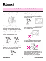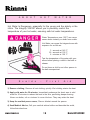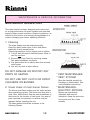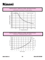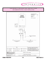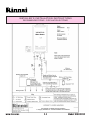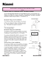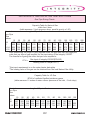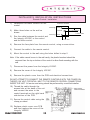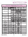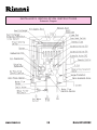
1
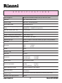
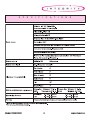
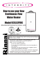
How to use your New Continuous Flow Water Heater Model V2532FFUC (Residential/Commercial indoor unit) R ANS Z21.10.3 • CSA 4.3 WARNING: If the information in these instructions is not followed exactly, a fire or explosion may result causing property damage, personal injury or death. Do not store or use gasoline or other flammable vapors and liquids in the vicinity of this or any other appliance. WHAT TO DO IF YOU SMELL GAS Do not try to light any appliance. Do not touch any electrical switch; do not use any phone in your building. Immediately call your gas supplier from a neighbor's phone. Follow the gas supplier's instructions. If you cannot reach your gas supplier, call the fire department. Installation and service must be performed by a qualified installer, service agency or the gas supplier. S P E C I F I C A T I O N S Type of appliance Temperature controlled continuous flow gas hot water system Operation With / without remote controls, mounted in kitchen, bathroom, etc. Exhaust system Direct Vent - Forced combustion Rinnai model number REU-V2532FFU(C-US C)-US Maximum/Minimum gas rate (Input BTU's) 180,000 BTU's - 15,000 BTU's Natural Gas 180,000 BTU's - 15,000 BTU's Propane Gas Hot water capacity, (50°F rise) 0.5 to 6.5 GPM Maximum hot water capacity, (35°F rise) 8.4 GPM Setpoint Temperature (without remote) 140 Factory setting - 1 20°F Temperature range (with remote) MCC controller : 96 - 180°F Approved gas type Natural or Propane - Ensure unit matches gas type it's being installed on. Installation Indoor Only Dimensions Height Width Depth Weight 49 Lbs. Efficiency rating 87% Noise level 49 dB (A) Connections Gas supply Cold water inlet Hot water outlet Ignition system Direct electronic ignition Electrical consumption Normal Standby Anti-frost protection Water temperature control Simulation feedforward and feedback. Water flow control Water flow sensor, electronic water control device, and electronic by-pass control device Recommended Minimum water supply pressure 20 PSI (Rinnai recommends 50-80 PSI for maximum performance) Maximum water supply pressure 150 PSI www.rinnai.us 23 5/8" 13 25/32" 8 13/16" 2 3/4" MNPT 3/4" MNPT 3/4" MNPT 75 watts 5.5 watts 100 watts Model V2532FFUC S Model V2532FFUC P E C I F I C 3 A T I O N S www.rinnai.us L I M I T E D W A R R A N T Y Rinnai Integrity Water Heater Models: REU-V2532FFU(C) and REU-V2532W(C) WHAT IS COVERED? This Warranty covers any defects in materials or workmanship, subject to the terms stated below. This Warranty applies only to productsthat are installed by a state qualified or licensed contractor. This Warranty is void if the installer has not atttended a Rinnai product knowledge class before installing this water heater. This Warranty extends to the originalpurchaser and subsequent transferees, but only while the product remains at the site of the original installation. This Warranty only extendsthrough the first installation of the product and terminates if the product is moved or reinstalled at a new location. HOW LONG DOES COVERAGE LAST? Item Heat Exchanger All other Parts and Components Period of Coverage 5 Years from Date of Purchase* 5 Years from Date of Purchase WHAT WILL RINNAI DO? Rinnai will repair or replace the product or any part or component that is defective in materials or workmanship*, except as set forth as follows. Rinnai will pay reasonable shipping costs, provided you obtain prior authorization from an Authorized Rinnai Distributor. Rinnai will not pay labor charges associated with the repair or replacement of the product or any part or component. All repair parts must be genuine Rinnai parts. All repairs or replacements must be performed by an individual or servicing company that has been authorized by Rinnai or its distributor. Replacement of the product or replacement of the heat exchanger may be authorized by Rinnai only. Rinnai does not authorize any person or company to assume for it any obligation or liability in connection with the replacement of a product or heat exchanger. If Rinnai determines that repair of a product is not possible, Rinnai will replace the product with a comparable product, at Rinnai’s discretion. * If the Heat Exchanger fails due to defect in material or workmanship within the fourth (4) or fifth (5) year from date of purchase, Rinnai will make the following allowances toward the purchase of replacement heat exchanger: Year of Failure Allowance 4 50% 5 25% HOW DO I GET SERVICE? You must contact an Authorized Distributor or Installer for the repair of a defective product under this Warranty. Failure to contact an Authorized Distributor or Installer will void the Warranty. For the name of the Authorized Distributor or Installer nearest you, please contact your local HVAC dealer or gas service technician, visit the Rinnai website (www.rinnai.us), call Rinnai at1-800-6219419 or write to Rinnai, 103 International Drive, Peachtree City, Georgia 30269. Proof of purchase is required. You can show proof of purchase with a dated sales receipt, or by completing and mailing the enclosed Warranty registration card within 30 days of purchasing the product. Please complete the enclosed Warranty registration card and mail it to Rinnai at the address shown on the card. Receipt of this card by Rinnai will constitute proof-of-purchase for this product. However, return of this Warranty registration card is not necessary in order to validate this Warranty. WHAT IS NOT COVERED? This Warranty does not cover any failures or operating difficulties due to accident, abuse, misuse, alteration, misapplication, force majeure, improper installation, improper maintenance or service, water quality, scale buildup, or for any other causes other than defects in materials or workmanship. This warranty does not apply to any product whose serial number or manufacture date has been defaced. This Warranty does not cover any product when used as a pool or spa heater. This Warranty does not apply if the water supply to the water heater does not meet the National Secondary Drinking Water Regulations, as set forth in the U.S. Code of Federal Regulations, 40 CFR, Chapter 1, Part 143. Rinnai is not liable for any special, incidental, indirect or consequential damages that may arise, including damage to person or property, loss of use, or inconvenience. Some states do not allow the exclusion or limitation of incidental or consequential damages, so the above limitation may not apply to you. LIMITATION ON IMPLIED WARRANTIES Any implied warranties of merchantability and fitness arising under state law are limited in duration to the period of coverage provided by this limited Warranty, unless the period provided by state law is less. Some states do not allow limitations on how long an implied Warranty lasts, so the above limitation may not apply to you. This Warranty gives you specific legal rights, and you may also have other rights which vary from state to state. www.rinnai.us 4 Model V2532FFUC C O N T E N T S Specifications ............................................................. 2,3 Warranty ......................................................................... 4 Owner's Installation Information .................................. 6 Features of your new Integrity .................................... 7 Safety Issues ................................................................ 8 Basic Operation ............................................................ 9 About Hot Water ......................................................... 10 Scalds-First Aid .......................................................... 10 Remote Control Operation ......................................... 11 Error Messages .......................................................... 12 Maintenance & Service Information .................... 13,14 Trouble Shooting and Common Questions .............. 15 For Your Safety Read Before Operating...................16 Operating Instructions .......................................... 16,17 Care & Lime Condition Warning ............................... 17 Model V2532FFUC 5 www.rinnai.us OWNER’S INSTALLATION INFORMATION IMPORTANT! All Rinnai water heaters MUST be installed by a state qualified or licensed contractor. Failure to comply with your local and state codes pertaining to water heater installations will void the warranty on said water heater(s). It is the responsibility of the person having the unit installed to ensure the contractor has the proper licences and permits for his state. In addition to the above, Rinnai requires all contractors attend a product knowledge class before installing our water heaters. This requirement MUST be met in order for your product’s warranty to be valid. Failure to comply with your local and state codes will result in non-compliance and void the warranty of the product being installed. This appliance must be installed in accordance with local codes, or in the absence of local codes, the National Fuel Gas Code, ANSI Z223.1 and/or the CAN/CGA-B149, Installation Codes. Install this product indoors, DO NOT install outdoors. Do Not use this appliance if any part has been underwater. Immediately call a qualified service technician to inspect the appliance and to replace any part of the control system and any gas control which has been underwater. Detailed instructions on the proper installation practices to follow for the installation of your new continuous hot water heater are included at the back of this manual. www.rinnai.us 6 Model V2532FFUC FEATURES OF YOUR NEW CONTINUUM F The Integrity V2532FFUC is one of the most advanced water heaters available. It produces hot water continuously at the temperature preset in the unit or at the temperature set on the remote temperature controller. Installation of the remote temperature controller is recommended for optimum performance. F The Integrity V2532FFUC never runs out of hot water. While electricity, water and gas supplies are connected, the Integrity V2532FFUC will produce hot water whenever the water flow rate through the unit exceeds 0.6 gpm and the temperature rise through the unit exceeds 45°F. F The gas burner lights automatically when the hot water tap is opened, and goes out when the tap is closed. Ignition is electronic, there is no pilot light. When the hot water tap is off, no gas is used. You save energy and money with the Integrity V2532FFUC. F The temperature of the outgoing hot water is constantly monitored by a built in sensor. If the temperature of the outgoing water rises to more than 6 degrees above the selected temperature (shown on the optional digital remote control) the gas burner will automatically go out. The gas burner will re-ignite once the outgoing hot water temperature falls below the selected temperature. F With the MCC-45-4US remote control installed the water temperature is adjustable from 96 to 180°F. The water temperature cannot be set to a temperature other than 140°F without the use of the MCC-45-4US remote control unit. If you require a temperature other than 140°F you must install the MCC-45-4US remote control unit. F F Error messages are displayed on the remote control units, simplifying service calls. F F The sound (noise) level from the Integrity V2532FFUC is very low. The Integrity V2532FFUC incorporates a device to limit the temperature fluctuations (cold water sandwich effect) when the water is rapidly turned off, then on again. To eliminate the cold water sandwich effect completely, the Integrity V2532FFUC can be installed with a circulation loop, with a small storage tank, as shown on page 24. The Integrity V2532FFUC is a very compact power vented device. It saves valuable floor and wall space. Model V2532FFUC 7 www.rinnai.us S A F E T Y I S S U E S Depending on the weather conditions and the length of the pipe between the Integrity V2532C and the tap in use, there may be a variation between the temperatures displayed at the Remote Control and the temperature of the water at the tap. Always check water temperature by hand before entering the shower or bath. The temperature may have been changed. 140 138°F The Integrity V2532C controls the water temperature automatically. To do this it sometimes needs to change the water flow accordingly. The water flow from the hot water tap may vary after the selected temperature at the Remote Control is altered. The water flow may also vary from summer to winter, as incoming water temperatures differ. Do not clean Remote Controls with solvents. Use a soft damp cloth. The vent/air intake should be positioned away from flammable materials, trees, shrubs, etc. The water temperature can only be adjusted between 96°F and 110°F when the hot water tap is open, and hot water is flowing. Vent Terminal Do not connect vent to natural draft vents or fireplaces, this unit can only be used with an approved Rinnai/Ubbink vent kit and components. Do not vent unit into other rooms. Vent terminal must be outside. www.rinnai.us 8 Model V2532FFUC B 1 A S I C O P E R A T I O N 2 Adjusting Temperature The setpoint temperature of the Integrity V2532(C) can only be adjusted by the user using the Remote Control. To adjust the setpoint temperature of the Integrity V2532(C), all hot water taps must be closed, and all circulating pumps turned off. TEMPERATURE CANNOT BE ADJUSTED WHEN ANY HOT WATER TAP IS OPEN, OR WATER IS FLOWING THROUGH THE WATER HEATER. To operate the Integrity V2532(C) simply turn any hot water tap on, or initiate water flow through the unit with a circulating pump. This will automatically light the burner providing hot water at the preset temperature. If the remote control has been installed, the green IN USE indicator will glow on the remote control. Simply press the or button until the required temperature is displayed on the Digital Monitor. Note: The Rinnai water heater will not provide hot water instantly at the hot water fixtures. Any cold water existing in the hot water lines must be purged first. 140°F The Remote Control will display the water heaters current setpoint temperature. There is a hot water scald potential if the thermostat is set to high. CHECK LOCAL CODES FOR THE MAXIMUM WATER TEMPERATURE SETTING ALLOWED WHEN USED IN NURSING HOMES, SCHOOLS, DAY CARE CENTERS, AND ALL OTHER PUBLIC USE APPLICATIONS. Rinnai recommends fixing the water heater setpoint temperature at 108°F for ALL public use applications. Model V2532FFUC 9 www.rinnai.us A B O U T H O T W A T E R Hot Water Is Dangerous, especially for the young and the elderly or the infirm. The Integrity V2532C allows you to precisely control the temperature of your hot water, ensuring safe hot water temperatures. Water Temperatures over 125°F can cause severe burns instantly or death from scalds. Hot Water can cause first degree burns with exposure for as little as: 3 seconds at 140 °F 20 seconds at 130 °F 8 minutes at 120 °F Test the temperature of the water with your elbow before placing a child in the bath or shower. BURN S c a l d s Do not leave a child or an infirm person in the bath unsupervised. - F i r s t A i d 1) Remove clothing; Remove all wet clothing, quickly. Wet clothing retains the heat. 2) Apply cold water for 30 minutes; Immediately submerge the burnt area in cold water for 30 minutes to reduce the heat in the skin, preventing deeper burning. Never use butter, oils or ointment to cover the burn. They may retain the heat. 3) Keep the scalded person warm; Place a blanket around the person. 4) Seek Medical Advice; Call your medical advice hotline and describe the scald, follow their directions. www.rinnai.us 1 0 Model V2532FFUC R E M O T E C O N T R O L O P E R AT I O N In Use Indicator Digital Monitor Indicates that a hot water tap is open. (The setpoint temperature cannot be adjusted when indicator is illuminated.) Indicates the selected water temperature. Error messages flash in the event of a failure. Maintenance Button Maintenance °F Pressing repeatedly shows sequence of error codes water heater has experienced. M Set Temperature In Use C Main Controller MCC - 45 - 4US H Thermostat Increase or decrease the desired water temperature. endless hot water system CAUTION: Hotter water increases the risk of scald injury. Before changing temperature setting, see instruction manual When the Main Controller MCC-45-4US is used in public use applications, it should be installed where it can not be adjusted by the public (i.e. a maintenance room or manager s office. 1. 2. 3. DIAGNOSTIC USE OF REMOTE CONTROL To Display Error Codes -- Press Maintenance Button, M. To sequence through stored error codes, press M followed by the H thermostat button. To Display Water Flow through water heater -- Press H thermostat button, hold for 2 seconds and simultaneously press M button. To Display Outlet Water Temperature -- Press C thermostat button, hold for 2 seconds and simultaneously press M button. Model V2532FFUC 1 1 www.rinnai.us E R R O R M E S S A G E S The Integrity V2532C has the ability to check its own operation continuously. If a fault occurs, an Error Message will flash on the Digital Monitor of the Remote Controls. This assists with diagnosing the fault, and may enable you to overcome a problem without a service call. Please quote the code displayed when inquiring about service. NOTE: Failure to remedy faults may result in severe burns, scalds, and/or death. Code Displayed Fault 10 Air Supply or Exhaust Blockage 11 No Ignition 12 Flame Failure Earthing Failure 14 Thermal Fuse Service Call 16 Over Temperature Warning Service Call 32 Outgoing Water Temperature Sensor Faulty Service Call 33 Heat Exchanger Outgoing Water Temperature Sensor Faulty Service Call 34 Combustion Air Temperature Sensor Faulty Service Call 52 Mod. Solenoid Valve Answer Abnormal Service Call 61 Combustion Fan Failure Service Call 71 Solenoid Valve Driving Circuit Faulty Service Call 72 Flame Sensing Device Faulty Service Call LC Scale build-up in Heat Exchanger Service Call www.rinnai.us Remedy 1 2 Check that nothing is blocking the air intake or exhaust. Check that the gas is turned on at the water heater, gas meter or cylinder. Check that the gas is turned on at the water heater and gas meter. Check for obstructions in flue outlet. Model V2532FFUC M A I N T E N A N C E & S E R V I C E I N F O R M AT I O N Warning: Always turn off the electrical power supply, the manual gas valve and the manual water control valve whenever servicing the unit. The Integrity V2532C should be checked by a Rinnai Certified Technician once a year. A Rinnai Certified Technician should perform any repairs that may be necessary. The following items should be checked each inspection: 1) The area around the Integrity V2532C unit should be free from combustible materials such as cloth, vegetation and building materials. (see page 8) 2) Check burners for presence of foreign debris. 3) Remove and clean the inlet water filter. 4) Keep the appliance area clear and free from combustible materials, gasoline, and other flammable vapors and liquids. 5) Do not obstruct flow of combustion and ventilation air. In the case of any fault or error message from the Integrity V2532C, first turn all hot water taps off. Wait for 5 seconds. Turn the hot water tap back on. If the error message still remains, call your Rinnai Authorized Service Representative or Rinnai at 800-621-9419. Should overheating occur or the gas supply fail to shutoff, turn off the manual gas control valve to the appliance. DO NOT ATTEMPT TO SERVICE YOUR Integrity V2532C YOURSELF. Call a Rinnai Authorized Service Technician or call Rinnai at 800-621-9419. Model V2532FFUC 13 www.rinnai.us M A I N T E N A N C E & S E R V I C E I N F O R M AT I O N MAINTENANCE SUGGESTIONS This water heater has been designed and constructed for a long performance life when installed and operated properly under normal conditions. Regular inspections, as outlined in this section, are strongly recommended as a means of keeping your heater operating efficiently. 1. Cleaning The water heater must be cleaned annually. Keep the water heater clear of dust and debris especially in and around burner. Cleaning procedures for the Integrity are as follows: 1) Turn off and disconnect electrical power. Allow to cool for one hour. 2) Remove the Front Panel by removing screws. See parts breakdown on panels. 3) Use pressurized air to remove dust from around main burner. 4) Use soft dry cloth to wipe cabinet. DO NOT DAMAGE OR DISTORT ANY PARTS OF HEATER. DO NOT USE WET CLOTH OR SPRAY CLEANERS ON BURNER. 2. Visual check of main burner flames. The burner must flame evenly over the entire surface when operating correctly. The flame must burn with a clear, blue, stable flame. See the parts breakdown of the burner for the location of view ports. Any and all parts removed for inspection or service must be replaced before operating the unit. The flame pattern should be as shown in the following Figures. www.rinnai.us 1 4 * VENT MAINTENANCE * VENT SYSTEM Must be checked annually for blockage or deterioration. See vent installation instructions. * MAINTENANCEELECTRIC MOTORS Motors are permanently lubricated and need no lubrication. Keep fan and motor free of dust and dirt, clean annually. Model V2532FFUC TROUBLE SHOOTING AND COMMON QUESTIONS Q - When I was using the hot water, the water got cold! A - If you adjusted the flow from the tap to lessen it, you may have gone below the minimum flow required. The Integrity V2532 requires 0.5 GPM to operate. If you mix the water with a tap and attempt to get a temperature well below the temperature being controlled by the unit, it may drop the flow below 0.5 GPM. Decrease the temperature supplied by the Integrity V2532 at the remote control or increase your total flow. Q - White smoke comes out of the exhaust! A - During colder weather when the exhaust temperature is hotter than the air, the exhaust fumes condense producing white steam. Q - When I open a A - Hot water must hot tap. I do not immediately get hot water! travel through your plumbing from the Integrity V2532 to the faucet. This can take up to 2 or more minutes depending upon your plumbing system. If hot water is disired instantly at the hot water fixture, a circulaton loop system must be installed. Please contact your plumber for details. Q - After I turn off the hot water tap, the fan on the Integrity V2532 continues to run! A - The fan is designed to be on for 65 seconds after the flow of water stops.This is to ensure constant water temperatures during rapid starting and stopping, as well as exhausting any residual gas flue products from the unit. Model V2532FFUC 15 www.rinnai.us FOR YOUR SAFETY READ BEFORE OPERATING Warning: If you do not follow these instructions exactly, a fire or explosion may result causing property damage, personal injury or loss of life. A. This appliance does not have a pilot. It is equipped with a direct ignition device which automatically lights the burner. Do not try to light the burner by hand. If you cannot reach your gas supplier, call the fire department. C. U. Use only your hand to operate remote control keypad. Never use tools. If the B. BEFORE OPERATING: Smell all around the remote keypad doesn't work, do not try to appliance area for gas. Be sure to smell repair it, call a qualified service technician. next to the floor because some gas is Force or attempted repair may result in a heavier than air and will settle on the floor. fire or explosion. WHAT TO DO IF YOU SMELL GAS Do not try to light any appliance. D. Do not use this appliance if any part has been under water. Immediately call a qualified service technician to inspect the appliance Do not touch any electric switch, do not use and to replace any part of the control system any phone in your building. and any gas control which has been under Immediately call your gas supplier from a water. neighbors phone. Follow the gas suppliers instructions. O P E R A T I N G I N S T R U C T I O N S 1) STOP! Read the safety information above before proceeding. © Closed manual valve (OFF position) 2) Set the thermostat to lowest setting. 3) Turn off all electric power to the appliance. 4) This appliance does not have a pilot. It is equipped with a direct ignition device which automatically lights the burner. Do not try to light the burner by hand. 5) Turn the manual valve located at gas inlet of the appliance clockwise to OFF. www.rinnai.us Open Manual valve ¨ (ON position) 6) Wait (5) minutes to clear out any gas. If you then smell gas, STOP! Follow B in the safety information above on this label. If you dont smell gas, go to next step. 1 6 Model V2532FFUC O P E R A T I N G 7) Turn the manual valve located at the gas inlet of appliance counterclockwise to ON. 8) Turn on all electric power to the appliance. I N S T R U C T I O N S 9) Set thermostat to desired setting. 10) If the appliance will not operate, Follow the instructions To Turn Off Gas To Appliance and call your service technician or gas supplier. To Turn Off Gas To Appliance 1) Set the thermostat to lowest setting. 2) Turn off all electric power to the appliance if service is to be performed. 3) Turn the manual valve at gas inlet of appliance clockwise to OFF CARE & LIME CONDITION WARNING Care of Units Exterior: Keep the exterior cabinet clean. Use a soft cloth and warm water when cleaning the cabinet. Do Not use volatile substances such as benzene and thinners, as they may ignite, or cause fading of the paint. Lime Condition Warning Signal: If you notice LC flashing on the remote key pad, this means the unit is beginning to lime up, and MUST be flushed. Contact a qualified Rinnai service technician to flush the appliance. Failure to flush the appliance when LC is flashing, will cause damage to the heat exchanger. Damage caused by lime build up is not covered by the units warranty. Model V2532FFUC 1 7 www.rinnai.us Installer’s Instructions All Rinnai water heaters MUST be installed by a state qualified or licensed contractor. Failure to comply with your local and state codes pertaining to water heater installations will void the warranty on said water heater(s). It is the responsibility of the person having the unit installed to ensure the contractor has the proper licences and permits for his state. In addition to the above, Rinnai requires all contractors attend a product knowledge class before installing our water heaters. This requirement MUST be met in order for your product’s warranty to be valid. Failure to comply with your local and state codes will result in non-compliance and void the warranty of the product being installed. Warnings ............................................................ 19 Performance Data .............................................. 20 Locating the vent terminal................................. 21 Dimensions ........................................................ 22 Recommended Piping ................................... 23,24 Venting .......................................................... 25,26 Gas Piping Sizing Charts ................................. 27 Gas Piping Notes .............................................. 28 Contents of Installers Manual Pressure Relief Valve ........................................ 29 Electrical Connection Notes .............................. 30 Wiring Diagram ............................................. 31,32 Lighting the Unit ................................................ 33 Remote Control ............................................. 34,35 Testing ................................................................ 36 Diagnostic Points .............................................. 37 Schematic Diagram ........................................... 38 Exploded View ........................................... 39 - 42 Parts List ................................................... 43 - 47 www.rinnai.us 800-621-9419 www.rinnai.us 1 8 Model V2532FFUC I N S TA L L E R S I N S TA L L AT I O N I N S T R U C T I O N S -Warnings- This manual must be followed exactly. 1) Read the safety issues completely before installing the Integrity V2532C. 2) This water heater is suitable for water (potable) heating or space heating. - The piping and components connected to the Integrity V2532C must be approved for use in potable water systems. - Toxic chemicals such as those used for boiler water treatment are NOT to be introduced to the potable water used for space heating. - The Integrity V2532C, if it will be used as a potable water source, it must not be connected to a system that was previously used with a nonpotable water heating appliance. 3) The Integrity V2532C is not suitable for use in pool or spa applications. 4) This unit is designed to be installed indoors using the proper vent piping to exhaust by-products of combustion to the outside environment. Contact your dealer or Rinnai for proper vent kits. DO NOT operate this unit without vent piping connected. Exhaust gasses must be expelled outside the home. All pipe joints shall be taped to help prevent leakage around joints. (Aluminum tape is recommended.) 5) Maintain proper space around the unit for proper servicing and operation. Minimum clearances from combustible materials are listed below. Top of Heater Back of Heater Front of Heater Sides of Heater Floor Vent/Air Intake 6 0 6 2 12 0 inches inch inches inches inches inches 6) Installer must install a Pressure relief valve. Pipe pressure relief discharge to a drain or outside environment (see page 29). 7) The appliance should be located in an area where leakage of the unit or connections will not result in damage to the area adjacent to the appliance or to lower floors of the structure. When such locations cannot be avoided, it is recommended that a suitable drain pan, adequately drained, be installed under the appliance. The pan must not restrict combustion air flow. Model V2532FFUC 19 www.rinnai.us I N S TA L L E R S I N S TA L L AT I O N I N S T R U C T I O N S I N T E G R I T Y O U T L E T F L O W D AT A I N S TA L L E R S I N S TA L L AT I O N I N S T R U C T I O N S INTEGRITY PRESSURE DROP CURVE www.rinnai.us 20 Model V2532FFUC I N S TA L L E R S I N S TA L L AT I O N I N S T R U C T I O N S Locating the vent terminal RECOMMENDED VENT/AIR INTAKE TERMINAL POSITION Terminals should be so positioned as to avoid products of combustion entering openings into buildings or other flues or vents. Vent/Air Intake Terminal positions - MINIMUM dimensions. Model V2532FFUC 2 1 www.rinnai.us INSTALLERS INSTALLATION INSTRUCTIONS Dimensions www.rinnai.us 22 Model V2532FFUC I N S TA L L E R S I N S TA L L AT I O N I N S T R U C T I O N S RECOMMENDED PIPING - BASIC INSTALLATION Model V2532FFUC 23 www.rinnai.us I N S TA L L E R S I N S TA L L AT I O N I N S T R U C T I O N S RECOMMENDED PIPING - CIRCULATION SYSTEMS V2532FFUC Water Heater Commercial Hot Water with Recirculation V2532WC - Preferred Method of Installation 1 Integrity V2532FFUC www.rinnai.us 24 Model V2532FFUC I N S T A L L E R ’ S I N S TALLA T I O N I N S T R U C T I O N S Venting The maximum allowable “Equivalent Length (D)” of vent pipe for the V2532C water heater is 41 feet with 3 bends (as determined using the formula below). If “D” is greater than 41, the vent/air intake piping is too long or there are too many elbows, redesign the vent pipe run. D = L + (B90 x 6) + (B45 x 1.5) D = L = B90 = B45 = Total Equivalent Length of vent system. Length of vent/air intake in feet. Number of 90° elbows. Number of 45° elbows. To help prevent condensation in the vent/air intake piping, the combustion fan has two dip switch settings. Dip switch number 1 is shipped from the factory set to the “OFF” position; this is suitable for the maximum vent/air intake length. Depending upon the vent/air intake length, Dip switch No. 1 may need to be adjusted to compensate fan speed. Read the following instructions, to determine which position this switch should be placed in. When the Equivalent Length of vent pipe, D, is more than 22 feet, leave dip switch number 1 in the “OFF” position. When the Equivalent Length of vent pipe, D, is 22 feet or less, dip switch number 1 must be moved to the “ON” position. Dip switch # 1 is located in the top row of dip switches, 1 through 8 on the PC board. See the diagram below to identify the proper switch. If you do not understand the following information, contact Rinnai at 1-(800)621-9419 for assistance. Do not alter dip switch number 1 before using formula, to determine the proper setting. Example #1: You have 6 feet of vent pipe, and two 90° elbows. Vent/air intake D = 6 + (2 x 6) + (0 x 1.5) piping length D = 18 Dip switch number 1 should be “ON” Example #2: You have 15 foot of vent pipe, one 90° elbow and two 45° elbows. D = 15 + (1 x 6) + (2 x 1.5) D = 24 Dip switch number 1 should be “OFF” Warning: All other dip switches with the exception of dip switch No.1, shown in the diagram below, MUST NOT be altered. Unauthorized adjustments can cause property damage, personal injury, scalding, or death. Model V2532FFUC 25 www.rinnai.us I N S T A L L E R ’ S I N S TALLA T I O N I N S T R U C T I O N S Venting Vent/Air Intake for Continuum V2532C Hot Water Systems The only vent/air intake systems approved for use with this appliance by CSA are the Rinnai/Ubbink vent system or the Heatfab Saf-T Vent SC vent system. The vent system must vent directly to the outside of a building and use outside air for combustion as indicated in the diagrams below. The minimum and maximum wall thickness for sidewall venting are: Minimum = 4” and Maximum = 20”. Horizontal Direct Vent Installation Horizontal Direct The Continuum V2532C may be installed on the internal surface of an external wall using a standard vent system kit. A typical installation is shown in the diagram to the right. The standard vent system kit consists of: vent termination kit • One • One discharge adaptor Horizontal Extension Installation Horizontal Extension The Continuum V2532C may also be installed on an internal wall which is near to an external wall. This can be done using a combination of extension tube(s), 90° or 45° elbow(s). The maximum “EQUIVALENT LENGTH” of the vent/air intake system is 41 feet, with a maximum of 3 bends, as calculated using the formula on page 29 (i.e. an installation with 23 feet of extension tubes, and three 90° elbows). The maximum vertical height of the vent/air intake system shall not exceed 5 feet unless an approved condensation collar is used. Vertical Direct Vent Installation The Continuum V2532C can also be installed in roof spaces or areas where vertical venting is required. Venting vertically can be acheived using a combination of extension tube(s), a vertical flue adaptor, a roof terminal, and flashing. The maximum “EQUIVALENT LENGTH” of the vent/air intake system is 41 feet, with a maximum of 3 bends, as calculated using the formula on page 29. However, the maximum HEIGHT of the vent system is limited to 21 feet. The maximum vertical height of the vent/air intake system shall not exceed 5 feet unless an approved condensation collar is used. www.rinnai.us 26 Maximum Height of 5' Without Condensate Collector Vertical Direct Roof Terminal Flashing Vertical Flue Adaptor Model V2532FFUC I N S TA L L E R ’ S I N S TA L L AT I O N I N S T R U C T I O N S Gas Pipe Sizing Charts Nominal Iron Pipe Size Inches Capacity Table for Natural Gas cubic feet / hour (table assumes .3 inch pressure drop, specific gravity of .60) Length of Pipe in Feet 10 20 30 40 50 60 70 80 90 100 125 150 3/4 278 190 152 130 115 105 96 90 84 79 72 64 1 520 350 285 245 215 195 180 170 160 150 130 120 1-1/4 1050 730 590 500 440 400 370 350 320 305 275 250 1-1/2 1600 1100 890 760 670 610 560 530 490 460 410 380 After determining the length of pipe required select the pipe size that will supply cubic feet per hour of gas required for the input rating of the Integrity V2532C. The formula for figuring the cubic feet per hour required is: CFH = 175 59 110 225 350 the 200 55 100 210 320 Gas Input of Integrity V2532C(BTU/HR) Heating Value of Gas(BTU/FT3) *Gas input requirement is on the water heater data plate *The heating value of the gas can be obtained from the local Natural Gas Utility Capacity Table for LP Gas BTUH of undiluted liquified petroleum gases (table assumes 11 inches of water column pressure at the inlet, .5 inch drop) Nominal Length of Pipe in Feet Iron Pipe Size Inches 10 20 30 40 50 60 70 1/2 275 189 152 129 3/4 567 393 315 267 237 217 196 1 1071 732 590 504 448 409 378 1-1/4 2205 1496 1212 1039 913 834 771 Model V2532FFUC 27 80 90 100 125 150 185 346 724 173 322 677 162 146 307 275 630 567 252 511 www.rinnai.us I N S TA L L E R S I N S TA L L AT I O N I N S T R U C T I O N S Gas Piping Notes 1) A manual gas control valve must be placed upon the gas inlet connection to the Integrity V2532C before it is connected to the gas line. A union can be used on the connection of the Integrity for the future servicing or disconnection of the unit. 2) Check the type of gas and the gas inlet pressure before connecting the Integrity V2532C. If the Integrity V2532C is not of the gas type that the building is supplied with, DO NOT connect the water heater. Contact the dealer for the proper unit to match the gas type. 3) Minimum and Maximum Gas pressures are listed below: * Minimum value is for input adjustment Natural Gas: WARNING: Minimum 7" WC Maximum 10.5" WC Propane Gas: Minimum 10"WC Maximum 1 3 . 5 " WC Conversion of this unit from natural gas to propane or propane to natural gas CANNOT be done in the field. 4) After completion of gas pipe connections, all joints including the heater must be checked for gas-tightness by means of leak detector solution, soap and water, or an equivalent nonflammable solution, as applicable. Caution: Since some leak test solutions, including soap and water, may cause corrosion or stress cracking, the piping must be rinsed with water after testing, unless it has been determined that the leak solution is non-corrosive. 5) The Integrity V2532C must be leak tested before it is placed into operation. 6) The Integrity V2532C and its individual shut-off valve must be disconnected from the gas supply piping system when pressure testing of the gas supply piping system at test pressures equal to or greater than 1/2 psi. 7) Always use approved connectors to connect the unit to the gas line. Always purge the gas line of any debris before connection to the water heater. 8) The Integrity V2532C must be isolated from the gas supply piping system by closing it's individual manual shutoff valve during any pressure testing of the gas supply piping system at test pressures less than 1/2 psi. 9) The Integrity V2532C's Installation location must provide adequate Combustion and Ventilation airflow. www.rinnai.us 28 Model V2532FFUC I N S TA L L E R S I N S TA L L AT I O N I N S T R U C T I O N S Water Piping Notes 1) A manual water control valve must be placed upon the water inlet connection to the Integrity V2532C before it is connected to the water line. Unions may be used on both the hot/cold water supply lines, for the future servicing or disconnection of the unit. 2) All soldering materials and piping must be compatible with potable water. 3) Purge the water line to remove from it all debris and air. Debris will damage the Integrity V2532C. 4) There is a wire mesh strainer on the Integrity V2532C's inlet to discourage the introduction of debris to the unit. It will need to be cleaned periodically. DO NOT operate unit without filter in place. WARNING: DO NOT reverse the inlet and outlet (cold and hot water) connections on the unit. This would cause the Integrity V2532C to operate dangerously or not at all. I N S TA L L E R S I N S TA L L AT I O N I N S T R U C T I O N S Pressure Relief Valve 1) ANSI code calls for the addition of an approved pressure relief valve to all water heating systems. 2) The pressure relief valve must meet the following criteria: The relief valve must comply with the standard for Relief Valves and Automatic Gas Shutoff Devices for Hot Water Supply Systems ANSI Z21. 22 and/or the standard CAN1-4.4 Temperature, Pressure, Temperature and Pressure Relief Valves and Vacuum Relief Valves. This relief valve must be rated at 150 PSI of pressure. 3) The relief valve should be added to the hot water outlet line per manufacturer's instructions. DO NOT place any other type valve or shut off device between the relief valve and the hot water heater. 4) The discharge from the pressure relief valve should be piped to the ground or into a drain system to prevent exposure or possible burn hazards to humans or other plant or animal life. Water discharged from the relief valve could cause severe burns instantly, scalds and/or death. 5) Do not plug the relief valve and do not install any reducing fittings or other restrictions in the relief line. The relief line should allow for complete drainage of the valve and the line. 6) If a relief valve discharges periodically, this may be due to thermal expansion in a closed water supply system. Contact the water supplier or local plumbing inspector on how to correct this situation. Do not plug the relief valve. 7) Pressure relief valve must be manually operated once a year to check for correct operation. Caution: See Item 4 before manually operating relief valve. 8) Should overheating occur or the gas supply fail to shut off, turn off the manual gas valve on the Integrity V2532C. Model V2532FFUC 29 www.rinnai.us I N S TA L L E R S I N S TA L L AT I O N I N S T R U C T I O N S Electrical Connection Notes WARNING: The Integrity V2532C must be electrically grounded in accordance with local codes or in the absence of local codes with the most recent edition of the National Electrical Code, ANSl/NFPA 70. In Canada, all electrical wiring to the Integrity V2532C should be in accordance with local codes and the Canadian Electrical Code, CSA C22.1 Part1. Do not rely on the gas or water piping to ground the metal parts of the water heater. CAUTION: Label all wires prior to disconnection when servicing controls. Wiring errors can cause improper and dangerous operation. Verify correct operation after servicing. 1 The Integrity V2532C requires 120VAC/ 60 HZ. Power from a properly grounded circuit, GFl. 2 An on/off switch must be provided and installed for the incoming 120VAC power. 3 Wire the Integrity V2532C exactly as shown in the wiring diagram on the next page and on the inside of the cover panel. The black wire is the hot leg wire; the white wire is the neutral wire. 4 A green screw is provided in the junction box for the grounding connection. Your disconnect switch should be a type that is suitable for outdoor use. Check National Electrical Codes for proper type switch to use in your area. www.rinnai.us 30 Model V2532FFUC I N S TA L L E R S I N S TA L L AT I O N I N S T R U C T I O N S Wiring Diagram Model V2532FFUC 31 www.rinnai.us I N S TA L L E R S I N S TA L L AT I O N I N S T R U C T I O N S Wiring Diagram www.rinnai.us 32 Model V2532FFUC I N S TA L L E R S I N S TA L L AT I O N I N S T R U C T I O N S Lighting the Unit WARNING: If you do not follow these instructions exactly, a fire or explosion may result causing property damage, personal injury or loss of life. 1) This water heater does not have a pilot. It is equipped with a direct ignition device which automatically lights the burner. DO NOT TRY TO LIGHT THE BURNER BY HAND. 2) Before operating the Integrity V2532C smell all around the unit for gas. Be sure to smell near the ground as leaking gas may settle there. 3) Turn the manual gas control valve on. STOP!! READ THE SAFETY ISSUES ON PAGES 8 4) Turn on any hot water tap. The Integrity V2532C should light and begin heating your water. If the Integrity V2532C fails to light 1) DO NOT ATTEMPT TO LIGHT BY HAND. 2) Turn off the electrical power to the unit. 3) Turn off the manual gas control. 4) Wait 5 minutes, if you smell gas, go to a neighbor's house and call the gas company or the fire department. If you do not smell gas, go to the next step. 5) Turn the manual gas control valve on. 6) Turn the electrical power to the unit on. 7) Turn on any hot water tap. 8) If the unit still fails to light, turn off the electricity and gas to the unit and call Rinnai 1-800-621-9419. Model V2532FFUC 33 www.rinnai.us I N S TA L L E R S I N S TA L L AT I O N I N S T R U C T I O N S Remote Control- General The remote control for the Integrity V2532C allows the customer to control the functions of the water heater and to diagnose certain fault conditions. The Main Controller model MCC-45-4US is intended to be installed in the kitchen or laundry area where the majority of the hot water is being used. NOTE: The MCC-45-4US has a temperature setpoint range of 96-180°F.Other setpoint tempertures must be set through dip switch settings, Contact Rinnai at 800-621-9419 for dip switch settings. Before installing the remote control, determine the most convenient location. When deciding on the best location for the remote control, please consider the following items: 1) Place the controller out of reach of small children or unauthorised users. 2) Avoid locations where the controller will become hot. (over a stove, near an oven or a radiant heater. 3) Avoid direct sunlight. (The digital monitor can be difficult to read in direct sunlight) 4) Avoid areas where the remote can be splashed with cooking water, oil or sauce. 5) The remote control cable carries low voltage, 12VDC digital. NOTE: Only one of controller can be connected to one Integrity V2532C water heater. (i.e. Installations with two controllers will not function properly.) www.rinnai.us 34 Model V2532FFUC I N S TA L L E R S I N S TA L L AT I O N I N S T R U C T I O N S Remote Control - Installation 1) 2) 3) Determine a suitable location for the control. Make three holes on the wall as shown. outline of remote securing screw 1 1/16 inches wire hole 3 1/4 inches securing screw Run the cable between the control and the Integrity V2532C or the control and the other control. 21/32 inch 4) Remove the face plate from the remote control, using a screw driver. 5) Connect the cable to the remote control. 6) Mount the control to the wall using the holes drilled in step 2. Note: If the cable cannot be run in the wall cavity, the plastic knockout should be removed from the top or bottom of the control to allow flush mounting with the wall 7) Disconnect the power from the Integrity V2532C. 8) Remove the cover of the Integrity V2532C. 9) Remove the plastic cover from the PCB and electrical connections. DO NOT ATTEMPT TO CONNECT THE REMOTE CONTROLS WITH THE POWER ON, THERE'S 120 VOLT POTENTIAL, NEXT TO THE REMOTE CONTROL CONNECTIONS INSIDE THE UNIT. All service and wiring should be performed by a certified installer. 10) Thread the cable through the access hole at the base of the unit and connect the wires to the control terminals on the right hand side bottom of the PCB. 11) Secure the control cable using the clamp provided. 12) Replace plastic cover over PCB and then replace the cover of the Integrity V2532C. Model V2532FFUC 35 www.rinnai.us I N S TA L L E R S I N S TA L L AT I O N I N S T R U C T I O N S Testing 1) Turn on the gas and water. 2) Check for water and gas leaks. Use soapy water to test for gas leaks. 3) Remove pressure test point screw, attach pressure gauge to test point. 4) Turn Power on. 5) Open any hot water tap fully. 6) Check test point or supply pressure in water columns per inch. Manifold Pressure: Supply pressure: Natural Gas 3.7" Hi. fire 0.77" Lo. fire Natural Gas Min. 7" Max. 10.5" LPG 4.2" Hi. fire 0.93" Lo. fire LPG Min. 10" Max. 13.5" NOTE: The pressure may be low due to too little flow, too high an incoming temperature, and/or undersized gas piping. Examine these areas before determining that the pressure needs to be adjusted. Contact Rinnai before adjusting manifold pressures at 1-800-621-9419. Failure to contact Rinnai, could void units warranty. 7) If it is determined that the gas pressure needs adjusting, first check the in coming pressure at the test point on the gas inlet. If it is correct follow the adjusting procedure contained in the pouch of the unit EXACTLY. If in doubt call Rinnai 1-800-621-9419. The regulator is pre-set at the factory, it should not need resetting. 8) Turn the hot water off. Turn the power off. Remove the pressure guage and replace the test point screw. Check for a gas leak around the test point screw. 9) Replace the front cover. 10) Turn the power back on. 11) Check the operation of the unit. Check the operation of each of the remote controls. Check the operation of the Power failure protection system. 12) Explain the proper operation of the Integrity V2532C to the customer. www.rinnai.us 36 Model V2532FFUC I N S TA L L E R S I N S TA L L AT I O N I N S T R U C T I O N S Diagnostic Points Model V2532FFUC 37 www.rinnai.us I N S TA L L E R S I N S TA L L AT I O N I N S T R U C T I O N S Schematic Diagram www.rinnai.us 38 Model V2532FFUC I N S TA L L E R S I N S TA L L AT I O N I N S T R U C T I O N S Exploded View - Cabinet Model V2532FFUC 39 www.rinnai.us I N S TA L L E R S I N S TA L L AT I O N I N S T R U C T I O N S Exploded View - Internals www.rinnai.us 40 Model V2532FFUC I N S TA L L E R S I N S TA L L AT I O N I N S T R U C T I O N S Exploded View - Internals Model V2532FFUC 4 1 www.rinnai.us I N S TA L L E R S I N S TA L L AT I O N I N S T R U C T I O N S Exploded View - Electrical www.rinnai.us 42 Model V2532FFUC I N S TA L L E R S I N S TA L L AT I O N I N S T R U C T I O N S Parts List Number 001 Casing Assembly Description Part Number Quantity 002 Wall Fitting Bracket-4 U242-111-5 2 003 Rubber Bushing U245-125 1 004 Connection Reinforcement Panel U245-120 1 005 Heat Protection Plate U245-107 1 006 Front Panel U245-110-2 1 007 Front Panel Packing BU195-167 1 008 Front Panel Packing Side AU115-163 2 100 Gas Control Assembly C36E-41-S 1 101 Screw AU39-965 2 102 Gas Connection (3/4NPT) CU195-1866 1 103 Burner Unit Assembly H73-110 1 104 Burner Case Front CH51-209 1 105 Burner Case Bottom Panel H73-112 1 106 Packing BH51-218 1 107 Lean and Rich Bunsen Burner Assembly B3A7-1 16 108 Burner Case Back Panel CH51-221 1 109 Damper H73-115 1 110 Manifold Assembly -A (LPG) U245-200-A 1 110 Manifold Assembly -B (Nat. G) U245-200-B 1 111 Packing of Combustion Chamber AU155-207-2 1 112 Lower Packing of Combustion Chamber H73-214 1 113 Screw C10D-5 1 Model V2532FFUC U245-100-2 43 1 www.rinnai.us I N S TA L L E R S I N S TA L L AT I O N I N S T R U C T I O N S Parts List Number 115 Combustion Chamber Front Plate Description Part Number Quantity 116 Electrode H73-120 1 117 Flame Rod AH41-216 1 118 Electrode Packing AH66-398 1 119 Electrode Holder AH66-393 1 120 Upper Packing of Combustion Chamber U245-262 1 121 Tube Joint U242-312 1 122 Pressure Tube AU161-665-C 1 125 Blower Motor All Assembly U245-550 1 126 Fan casing Assembly U245-555 1 127 Fan Connecting Bracket BH29-606 1 128 Fan Connecting Packing AU183-562 1 129 Blower Motor U245-560 1 130 Bell Mouth U245-558 1 131 Bellows Connecting Bracket/Intake Duct U245-566 1 132 Combustion Chamber Bracket U245-255 1 135 Air Inlet Box Assembly U245-400 1 136 Bellows Connecting Bracket/Fan U245-408 1 137 Bellows U245-409 1 138 Bellows Clamping Ring U245-567 1 139 Air Inlet Box Assembly U245-410 1 140 Exhaust Bracket U245-434 1 141 Exhaust Bracket Holder U245-435 2 www.rinnai.us U245-261 44 1 Model V2532FFUC I N S TA L L E R S I N S TA L L AT I O N I N S T R U C T I O N S Parts List Number 142 Air Inlet Box Cover Description Part Number Quantity 145 Heat Exchanger Complete Assembly U245-690-C 1 400 Water Inlet (3/4NPT) H73-501-2 1 401 Water Flow Servo & Sensor Assembly M8E-6-5 1 402 Rectifier M8D1-15 1 403 By-pass Servo Assembly M6J-1-3 1 404 Stop Bracket AH69-310 2 405 Plug Band H73-512 1 406 Water Filter Assembly H73-511 1 407 Filter Plug H73-510 1 408 Hot Water Outlet (3/4NPT) U245-865-3 1 409 Stop Bracket AU162-1876 1 410 Plug Band Small AU103-413 1 411 Drain Valve AU142-444 1 700 PCB U245-500 1 701 Surge Protector BBF9-630 1 702 PCB Cover-Side U245-774 1 703 PCB Cover-Front BU168-707 1 704 Transformer Assembly ET-281 1 705 PCB Bracket U245-257 1 706 Ignitor EI-189 1 707 High Tension Cord BH38-710-240 1 708 Electrode Sleeve AU206-218 1 709 Thermistor BH45-650 2 Model V2532FFUC U245-419 45 1 www.rinnai.us I N S TA L L E R S I N S TA L L AT I O N I N S T R U C T I O N S Parts List Number 710 Description Thermistor Clip Large Part Number Quantity 711 Thermal Fuse Clip U217-676 5 712 Frost Sensing Switch U242-511 1 713 120V Anti-Frost Heater Assembly U245-620 1 714 Heater Connecting Harness U245-621 1 715 120V Valve Heater Assembly U245-622 1 716 Anti-Frost Heater Clip CF29-742 2 717 Anti-Frost Heater Clip A AU111-653 1 718 Anti-Frost Heater Clip AU100-721 1 719 Inlet Air Thermistor BH50-730-2 1 720 Power Supply Harness AU195-1876 1 721 Fuse Harness BU195-1630 1 722 100V Harness U245-601 1 723 Solenoid Valve Harness U245-602 1 724 Sensor Harness U245-603 1 725 Thermal Fuse Harness U245-610 1 726 Mold-Type Over Heat Switch BU129-824-2 1 800 Screw ZIHD0510UK 8 801 Screw ZAD0408UK 4 802 Washer AU33-184 4 803 Screw CP-21478-412 3 804 Screw U217-449 1 805 Screw ZAA0408UK 3 810 O-ring M10B-2-4 2 www.rinnai.us CP-90172 46 1 Model V2532FFUC I N S TA L L E R S I N S TA L L AT I O N I N S T R U C T I O N S Parts List Number Description Part Number Quantity 812 O-ring M10B-13-4 1 813 O-ring M10B-2-18 2 814 O-ring M10B-2-16 2 815 O-ring M10B-2-14 2 816 O-ring M10B-2-7 1 817 O-ring M10B-1-24 1 818 Packing C36E1-6 2 888 V2532FFUC Owners Manual U245-661 1 - Package Spec Sheet PWB-261 1 - Manual 3/4 gas control valve BU195-1865 1 - Commercial remote control kit MCC-45-4US 1 - Horizontal Discharge Adapter 50710327 - - Wall Discharge Terminal (for wall thicknesses from 4 to 20) 50223098B - - Vertical Discharge Adapter 224064 - - Roof Discharge Terminal 184118 - - Condensate Collector 224069 - - Roof Flashing - Flat Roof 146141 - - Roof Flashing - 1/12 to 6/12 Pitch 50171948 - - Roof Flashing - 6/12 to 12/12 Pitch 50171960 - - Roof Flashing - 12/12 to 16/12 Pitch 50171953 - - 10 Pipe Extension 224051 - - 19.5 Pipe Extension 224052 - - 39 Pipe Extension 224053 - - 90 Degree Vent Pipe Elbow 224063 - - 45 Degree Vent Pipe Elbow 224050 - - Vent Pipe Clamp 169044 - 811 O-ring Model V2532FFUC M10B-2-3 47 1 www.rinnai.us A sk about Rinnais other fine products: The Silent Servant *North Americas only vent-free convection heater *99% efficient *whisper quiet *perfect for hard to heat areas The Energy Savers *Direct Vent Heating with style and performance *whisper quiet *available with multi-step set back thermostats The Infra-reds *Vent free radiant heaters *99.9% efficient *Heat like the sun Portable Cooking Products *One, two and two burner with broiler models. *Perfect for camping, a picnic or a tailgate party www.rinnai.us U245-661~04 Printed in Japan 2003.05