1
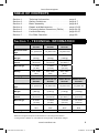
CURRIE TECHNOLOGIES®
300 Series
500CD Series
4.0 Series
650CD Series
400 Series
750CD Series
900CD Series
OWNER’S
MANUAL
(CHAIN DRIVE SCOOTER SERIES)
You must read and understand this manual before using this scooter
!
ATTENTION
TWIST AND GO! To start scooter turn the power switch “ON”. Twist
throttle and go.
Chain Drive Scooters.indd 1
3/18/2008 12:17:47 PM
Currie Technologies®
PLEASE DO NOT RETURN
THIS ITEM TO THE STORE.
For questions or assistance on assembly contact
Currie Technologies® Customer Service toll free
(800) 377-4532
Monday - Friday
8:00 am - 4:00 pm (PST)
OR
Consult the trouble shooting guide of the owner’s manual or
visit our website at www.CurrieTech.com
IMPORTANT - Activate your warranty by registering your new Currie
Technologies® product within 10 days of purchase by visiting our website at
www.CurrieTech.com.
Retain this manual along with the original sales receipt. Record the
product serial number (S/N), place of purchase and date of purchase
below.
Model Name : __________________________________________
S/N : __________________________________________________
Place of Purchase : ______________________________________
Date of Purchase : _______________________________________
2
Chain Drive Scooters.indd 2
Customer Service 1-800-377-4532
3/18/2008 12:18:13 PM
Currie Technologies®
TABLE OF CONTENTS
Section
Section
Section
Section
Section
Section
Section
1.
2.
3.
4.
5.
6.
7.
.
.
.
.
.
.
.
.
.
.
.
.
.
.
.
.
.
.
.
.
.
.
.
.
.
.
.
.
. Technical Information . . . . . . . . . . . .
. Safety Guidelines . . . . . . . . . . . . . . .
. Basic Assembly . . . . . . . . . . . . . . . . .
. Repair and Maintenance . . . . . . . . . .
. Frequently Asked Questions (FAQ’s) .
. Limited Warranty . . . . . . . . . . . . . . . .
. Pre-Ride Checklist . . . . . . . . . . . . . .
.
.
.
.
.
.
.
.
.
.
.
.
.
.
.
.
.
.
.
.
.
. page
. page
. page
. page
. page
. page
. page
3
4-7
8-9
10-33
34-35
36-37
38
Section 1 - TECHNICAL INFORMATION
300 Series
Scooter
4.0 Series
Scooter
400 Series
Scooter
Minimum Rider
Age
13 years old
13 years old
13 years old
Maximum Rider
Weight
180 lbs
(82 kg)
180 lbs
(82 kg)
240 lbs
(109 kg)
Up to 12 mph
(20 km/h)
Up to 12 mph
(20 km/h)
Up to 15 mph
(24 km/h)
7 miles
(11 km)
7 miles
(11 km)
8 miles
(13 km)
24V 10Ah
SLA
24V 10Ah
SLA
24V 10Ah
SLA
Maximum
speed*
Max Range*
Battery
6-8 hours
6-8 hours
6-8 hours
500CD Series
Scooter
650CD Series
Scooter
750CD Series
Scooter
900CD Series
Scooter
Minimum Rider
Age
13 years old
13 years old
13 years old
13 years old
Maximum Rider
Weight
240 lbs
(109 kg)
260 lbs
(118 kg)
260 lbs
(118 kg)
260 lbs
(118 kg)
Up to 15 mph
(24 km/h)
Up to 15 mph
(24 km/h)
Up to 15 mph
(24 km/h)
Up to 15 mph
(24 km/h)
8 miles
(13 km)
12 miles
(19 km)
12 miles
(19 km)
12 miles
(19 km)
Battery
24V 10Ah
SLA
24V 12Ah
SLA
24V 12Ah
SLA
24V 12Ah
SLA
Charging time**
6-8 hours
8-10 hours
8-10 hours
8-10 hours
Charging time**
Maximum
speed*
Max Range*
*Maximum range and speed varies based on rider weight and terrain.
**Charge time is based on new batteries charged with a standard charger.
www.CurrieTech.com
Chain Drive Scooters.indd 3
3
3/18/2008 12:18:13 PM
Currie Technologies®
Section 2 - SAFETY GUIDELINES
LIMITATIONS OF SAFETY AND WARNING NOTICES
!
WARNING
This owner’s manual includes important safety
guidelines and maintenance instructions. Failure to
read, understand and follow the instructions in this
manual may lead to serious injury or even death.
INSURANCE NOTICE
Your insurance policies may not provide coverage for accidents
involving the use of this electric scooter. To determine if coverage
is provided, you should contact your insurance company or agent.
»
»
»
»
»
This product is intended for use under adult supervision only. Even
under adult supervision serious injuries or even death can occur.
Always ride within your capabilities and use common sense, do
not ride at night. You are using this product at your own risk. Never
operate this product at a speed which is too fast for your skills.
Always drive at low speed on dusty surfaces.
This product is not intended, designed or licensed for roadway
use. This product is intended for use outdoors and on a private,
closed course only. Ride only on dry, smooth, solid paved surfaces
without motor vehicle traffic. Never use this product on roadways
(paved, gravel or dirt), sidewalks, driveways, parking lots near motor
vehicles, on or near steep inclines or steps, swimming pools or other
bodies of water.
This product is not regulated by transportation regulations (that is,
Department of Transportation (DOT) or state law).
The laws and ordinances vary greatly from municipality to
municipality. It is your responsibility to know and abide by your
local restrictions. We recommend you contact your local police or
Department of Motor Vehicles to find out about any special laws or
rules governing the use of this product where you live.
4
Chain Drive Scooters.indd 4
Customer Service 1-800-377-4532
3/18/2008 12:18:13 PM
Currie Technologies®
!
WARNING
Never operate this product without proper training
or instructions.
Children under 13 years old should never operate the these scooters. Rider
age does not necessarily mean that they are qualified to operate this product. A parent should never allow this product to be used by an individual
not having the ability, coordination, maturity, skills and strength to operate it
safely and in a controlled manner.
!
WARNING
!
WARNING
Maximum rider weight is 180 lbs, (82 kg) for the 300
and 4.0 series scooters, 240 lbs. (109 kg) for the 400
and 500CD series scooters and 260 lbs. (118 kg) for
the 650CD, 750CD and 900CD series scooters; never
exceed it. Rider weight does not necessarily mean that
they are qualified to operate this product.
Never modify this product through improper installation,
modification of existing parts or use of non-authorized
accessories. Doing so may result in denied warranty
claims.
Before every ride, make sure the “Easy Fold Handlebar Hinge” is in the
fully upright position. Be sure the locking pin is fully engaged and the quick
release lever is in the “closed” position
This product is designed to be used by only one person at a time. Never carry passengers or allow more than one person to use this product at a time.
Always wear an approved helmet that fits and is worn properly when using
this product. Also recommended is to always wear knee pads, elbow pads,
eye protection (goggles or face shield), gloves, boots, long sleeved shirt or
jacket and long pants. Never operate this product barefoot or in sandals as
this increases the risk of injury.
Always keep both hands on the handlebars (hand grips) and both feet on the
footboard during operation.
Always drive slowly and pay extra attention when operating on unfamiliar
terrain. Always be alert to changing terrain conditions when operating this
product.
www.CurrieTech.com
Chain Drive Scooters.indd 5
5
3/18/2008 12:18:14 PM
Currie Technologies®
Never operate on excessively rough, slippery or loose terrain.
Practice turning at low speeds before attempting to turn at faster speeds. Do
not turn at excessive speed as this could increase the risk of injury.
Always check for obstacles before operating in a new area. Never attempt to
operate over large obstacles, such as large rocks or fallen trees.
Do not ride with headphones. They mask traffic sounds and emergency vehicle sirens, distract you from concentrating on what is going on around you,
and their wires can tangle in the moving parts of the scooter, causing you to
lose control.
Do not do stunts, wheelies, jumps or any other type of dangerous riding.
They can cause severe injury to you and damage your scooter.
Do not lean the scooter excessively as this may allow parts of the scooter
to contact the ground and may result in lose of control or damage to the
scooter.
Do not touch the motor or brakes as they can become hot from use.
WET WEATHER RIDING
This product is not meant for use in the water (damp roads, puddles, rain,
streams, etc.). Never immerse this product in water as the electrical and
brake systems may be damaged.
BATTERY CHARGER
The charger and charger port should be regularly inspected for damage
(cord, plug, enclosure, etc.). If damage is found stop using the charger until it
can repaired or replaced.
!
WARNING
The charger is not a toy and should be kept out of reach
children at all times.
Always disconnect the charger from the wall outlet and
the charger port on the scooter when not using it.
!
WARNING
6
Chain Drive Scooters.indd 6
Do not charge your battery for more than 24 hours at
one time.
Customer Service 1-800-377-4532
3/18/2008 12:18:14 PM
Currie Technologies®
STARTING
1. Turn the power switch to the “ON” position
2. Place one foot on the deck with both hands on the handlebars.
3. Slowly twist the throttle to operate the motor.
4. Place the other foot on the deck once you have properly balanced
yourself.
STOPPING
1. To slow down or come to a stop, allow the throttle to completely
return to its “zero speed” position
2. Squeeze the brake lever(s) on the handlebar to come to a safe stop.
(Note: It is not necessary to skid the wheel in order to slow or stop
the scooter)
!
WARNING
Skidding the wheel can damage the wheel and is not
covered by the warranty!
STORING YOUR SCOOTER
1. When you are done using the scooter, turn the power switch to the
“OFF” position.
2. Always be sure to fully charge batteries (6-10 hours depending on
battery size) at least every 30 days.
3. Plug the charger into the scooter then plug the charger into the wall
outlet. Do not charge your battery for more than 24 hours at one
time.
5 MINUTE SLEEP MODE
Scooters are equipped with a 5 minute sleep mode. If no activity is detected
after 5 minutes the scooter will go into stasis mode to conserve the batteries.
To restart, cycle the power switch Off then On.
!
WARNING
Never store your scooter in Sleep Mode as battery
power will still be used by the scooter. Always be sure to
turn the power switch to the “OFF” position.
www.CurrieTech.com
Chain Drive Scooters.indd 7
7
3/18/2008 12:18:14 PM
Currie Technologies®
Section 3 - BASIC ASSEMBLY & SET-UP
IMPORTANT: Some adult assembly required. Before using your scooter
please be sure to read and follow the basic assembly, set-up and operating
instructions. Following these instructions will help insure safe riding.
TOOLS REQUIRED:
Listed below are the tools you may need to assemble and adjust your Electro-Drive™ scooter depending on model:
•
•
•
•
10mm
13mm
15mm
17mm
box wrench
box wrench
box wrench
cone wrench
•
•
•
•
•
4mm hex key wrench
5mm hex key wrench
6mm hex key wrench
Phillips screwdriver
Bicycle tire pump
STEPS FOR BASIC ASSEMBLY
1. Remove scooter from carton. Remove all of the packaging materials
from the scooter.
2. Install the front wheel (certain models will have the front wheel
already installed) being sure to properly install the safety washers.
Align the front wheel in the fork and tighten the axle nuts. Wait until
after you have installed the handlebars to connect the front brake (if
your scooter is so equipped).
3. Install the handlebars onto the stem, align and tighten.
4. Unfold the stem hinge. Be sure the locking pin is fully engaged and
close the quick release lever.
5. The brake(s) come pre-assembled from the factory (some scooters
have one brake while others have two brakes). However, you need
to check to make sure it is connected and operating properly. Test
the brake lever(s) by squeezing it. It should stop the wheel(s) easily
and NOT come in contact with the handlebar. If the brake lever(s)
needs adjusting, refer to pages 19-20 for instructions. If the brake(s)
does not work properly, DO NOT RIDE THE SCOOTER. Call Customer Service at 1-800-377-4532 for further assistance.
6. Install the seat assembly, if so desired, by fully sliding the seat
tube into the frame and securing the pinch bolt. If the seat tube is
equipped with an indexing pin be sure to align this properly with the
frame.
7. Install the seat onto the seat tube if not already done and align
saddle angle and tilt and tighten accordingly.
8. Remove the battery charger from its box. Make sure the power
switch on the scooter is in the “OFF” position. Connect the charger
Customer Service 1-800-377-4532
8
Chain Drive Scooters.indd 8
3/18/2008 12:18:14 PM
Currie Technologies®
to the scooter first then plug the charger into the wall socket. Allow
the batteries to charge a full 6-10 hours (depending on the size of
batteries) before first use. Refer to page 17 for complete Battery
Care instructions
9. Before every ride, test the throttle with the power switch in the
“OFF” position. Twist the throttle, it should twist easily and immediately spring back to the starting position when you release it. If the
throttle does not work properly, DO NOT RIDE THE SCOOTER. Call
Customer Service at 1-800-377-4532 for further assistance.
10. Check tire pressure and inflate to recommended pressure as necessary.
!
WARNING
Before you ride the scooter, make sure you have
tightened all parts. Riding with a loose handlebar, front
wheel, brake, seat assembly, etc. may cause a rider to
fall, possibly damaging the scooter and causing serious
injury.
www.CurrieTech.com
Chain Drive Scooters.indd 9
9
3/18/2008 12:18:14 PM
Currie Technologies®
Section 4 - REPAIR & MAINTENANCE
IMPORTANT: Some adult assembly required.
HANDLEBAR ASSEMBLY AND ADJUSTMENT
Electro-Drive™ scooters are equipped with an folding stem hinge. Take care
not to pinch your hands or fingers in the hinge when you are folding and
locking the handlebar in place. Additionally be careful not to pinch or crimp
the brake and throttle cables in the hinge whenever you fold the stem hinge.
1.
Insert the stem into the
steerer tube. Be sure
to insert stem past the
“Minimum Insertion Mark”.
2.
Open the stem quick release
(QR) lever (Ref Photo A)
and rotate it forward out
of the upper plate (Ref
Photo B, step 1). Slide the
QR retention pin (silver)
sideways (Ref Photo B, step
2) to disengage it from the
upper plate.
!
WARNING
Photo A
If the
quick release lever is either
too tight (cannot be flipped to
its fully locked position) or is
too loose (can be too easily
flipped to its locked position)
refer to the “QR Lever Adjustment” on page 14.
1
2
Photo B
10
Chain Drive Scooters.indd 10
Customer Service 1-800-377-4532
3/18/2008 12:18:14 PM
Currie Technologies®
3.
Open the stem hinge to
access the steerer bolt
(6mm Allen Bolt or 13mm
Hex Bolt).
4.
Loosely tighten the steerer
bolt. The stem is held in
position with the expander
bolt and wedge.
5.
Slide the QR retention pin
(silver) sideways (Ref Photo
A). Close the stem hinge
(Ref Photo B).
Photo A
Photo B
www.CurrieTech.com
Chain Drive Scooters.indd 11
11
3/18/2008 12:18:16 PM
Currie Technologies®
6.
Rotate the stem QR lever
forward into of the upper
plate (Ref Photo A). Close
the stem QR lever (Ref
Photo B) being sure the QR
retention pin (silver) is fully
engaged with the upper
plate.
Photo A
Photo B
7.
Install the handlebars onto
the stem, align and tighten.
12
Chain Drive Scooters.indd 12
Customer Service 1-800-377-4532
3/18/2008 12:18:18 PM
Currie Technologies®
8.
Align the handlebars to the
front wheel. The handlebars
must be perpendicular to the
front wheel.
9.
Repeat steps 2 and 3
to once again access the
steerer bolt (6mm Allen Bolt
or 13mm Hex Bolt). Fully
tighten the steerer bolt.
The stem is held in position
with the expander bolt and
wedge.
10. Repeat steps 5 and 6
to once again secure the
folding stem. Be sure the
QR retention pin (silver) is
fully engaged with the upper
plate.
!
WARNING
If you are unable to lock the handlebar folding hinge
properly, or its Quick- Release lever, or properly secure
the two main handlebar parts to the scooter, DO NOT
RIDE THE SCOOTER. Contact Currie Technologies®
Customer Service at 1-800-377-4532 for further
instructions. Failure to do so may result in serious injury
or death to the rider or severe damage to the scooter.
www.CurrieTech.com
Chain Drive Scooters.indd 13
13
3/18/2008 12:18:20 PM
Currie Technologies®
QR LEVER ADJUSTMENT:
If the quick release lever is either
too tight (cannot be flipped to its fully
locked position) or is too loose (can
be too easily flipped to its locked
position) you will need to adjust the
QR (Quick Release) Lever.
Open the QR lever (Ref Photo A) and
adjust the 10mm nut underneath the
center pin (Ref Photo B).
If the QR lever was too tight initially
you will need to loosen the nut a 1/4
turn at a time. Test the adjustment
you have made by closing the QR
lever (Ref Photo C). The lever should
be tight in its closed position and unable to vibrate loose.
If the QR lever was too loose initially
you will need to tighten the nut a 1/4
turn at a time. Test the adjustment
you have made by closing the QR
lever (Ref Photo C). The lever should
be tight in its closed position and unable to vibrate loose.
Photo A
Photo B
Repeat adjustment as necessary
until QR lever is properly tightened.
!
WARNING
If you are unable
to properly adjust the QR lever DO
NOT RIDE THE SCOOTER. Contact
Currie Technologies® Customer
Service at 1-800-377-4532 for further
instructions. Failure to do so may
result in serious injury or death to the
Photo C
rider or severe damage to the scooter.
14
Chain Drive Scooters.indd 14
Customer Service 1-800-377-4532
3/18/2008 12:18:22 PM
Currie Technologies®
BATTERY PACK, CHARGER PORT AND CHARGER
ELECTRO-DRIVE™ SMART CHARGER: The Electro-Drive™ scooter comes
with its own Electro-Drive™ Smart Charger that connects with an easy-access charger port for recharging the batteries. This charger unit has lights
that show the battery charge status. Refer to the instructions that appear on
the charger unit and its instructions.
!
WARNING
Use only a Currie Authorized Smart Charger to charge
the batteries. Using any other charger may damage the
batteries and void your warranty.
HOW TO CHARGE THE BATTERIES
1. IMPORTANT: Be sure the
power switch on the scooter
is in the “OFF” position. (Ref
Photo A)
2. Rotate open the charger port
cover (Ref Photo B).
3. Insert the Battery Charger’s
XLR (Male) plug into the CharPhoto A
ger Port (Ref Photo C).
4. Plug the Battery Charger’s AC
plug into a standard, grounded
110V AC outlet.
5. Let the batteries charge until
the charger lights indicate that
the batteries are fully charged,
then unplug the charger from
the scooter and the AC outlet.
Batteries like to have a full charge, so Photo B
always be sure to recharge them fully
after each ride. If you leave them in
a run-down condition, without quickly
recharging them, it will shorten their
life expectancy. The charger may get
warm to the touch, so make sure you
charge them in an open area and
do not lay anything on the charger
unit while charging. Although you
cannot over-charge the batteries
Photo C
www.CurrieTech.com
Chain Drive Scooters.indd 15
15
3/18/2008 12:18:24 PM
Currie Technologies®
using the Currie “Smart Charger”, we
recommend that you do not leave the
charger plugged in for more than 24
hours.
CHANGING THE BATTERY PACK
1. IMPORTANT: Be sure the
power switch on the scooter is
in the “OFF” position.
2. Remove the deck by unscrewing the “D” ring deck retention
screw then lifting the deck off.
(Ref Photo A)
Photo A
3. Remove the battery pack out of
the scooter’s battery tray. (Ref
Photo B)
4. Disconnect the battery power
pack connector (cut zip tie
holding the wire connector, if
necessary) (Ref Photo C)
5. Place the new or fully charged
battery pack into the battery
tray.
6. Reconnect the battery pack
connector and place all of the
cables into the tray.
7. Re-install the deck and secure Photo B
with the “D” ring deck retention
screw.
Photo C
16
Chain Drive Scooters.indd 16
Customer Service 1-800-377-4532
3/18/2008 12:18:26 PM
Currie Technologies®
BATTERY CARE AND MAINTENANCE
Not doing any and/or all of the following may lead to reduced performance
and/or permanent damage to the batteries. Batteries that have been damaged by not following the below steps will need to be replaced and are not
covered under warranty.
•
•
•
•
•
Always be sure to fully charge batteries before first use (6-10
hours depending on size).
Always be sure to fully charge batteries after each and every use
(6-10 hours depending on size).
Be sure to charge batteries at least every 30 days.
Do not store batteries below 50º Fahrenheit and never allow batteries to freeze (below 32º Fahrenheit).
Always be sure to turn the scooter “OFF” after each use via the
On/Off power switch.
SLA (SEALED LEAD ACID) BATTERY CONDITIONING
SLA batteries should always be fully charged (charge time of 6-10 hours
depending on amperage of battery) before first use. This will help obtain
optimum performance.
SLA batteries have a “break-in” cycle consisting of ~ three discharge/charge
cycles before they will reach optimum performance. This involves three
complete discharges and three complete recharges (charge time of 6-10
hours depending on amperage of battery and strength of the charger). After
this initial “break-in” cycle the batteries will have increased performance and
less line voltage fluctuations under load, as indicated by the throttle LED’s.
FUSE
In the event of an overload the fuse will pop and need to be replaced. In this
instance replace only with approved part from Currie Technologies®.
!
WARNING
Risk of fire, Do not bypass fuse.
www.CurrieTech.com
Chain Drive Scooters.indd 17
17
3/18/2008 12:18:29 PM
Currie Technologies®
THROTTLE AND BRAKE OPERATION & ADJUSTMENT
THROTTLE OPERATION
The speed of the Electro-Drive™
scooter is controlled by a griptwist throttle, which is located on
the handlebar.
To check the throttle operation,
turn the power switch to the
“OFF” position. Fully twist the
throttle then quickly release it.
The throttle is spring loaded and
should immediately spring back to
its original (also know as “Zero Position) position.
To accelerate, twist the right hand throttle grip towards you as you stand
on the deck plate. The more you twist the throttle, the faster the motor will
propel the scooter until you reach the scooter’s top speed.
To go slower, or coast to a slower speed, allow the throttle to spring back to
its original position. To decelerate or come to a complete stop, release the
throttle and allow it to return automatically to its original position. Then squeeze
the brake lever(s) to activate the brake(s). Remember to release the throttle
whenever you apply the brake.
!
WARNING
!
WARNING
The throttle and its components are fully assembled and
tested at the factory. Do not attempt to adjust them at
any time. If you feel the throttle and/or components are in
need of service DO NOT RIDE THE SCOOTER! Contact
Currie Technologies® Customer Service number at 1-800377-4532.
If you do not fully understand how to operate your scooter
throttle properly, DO NOT RIDE YOUR SCOOTER. Contact Currie Technologies Customer Service for information
and instructions at 1-800-377-4532.
HOW TO USE THE THROTTLE LED’S
When the throttle is engaged (powering the motor) and the scooter is in motion, the LED’s on the throttle indicate instantaneous line voltage as measured at the battery terminals -- and not the available energy in the battery
pack.
18
Chain Drive Scooters.indd 18
Customer Service 1-800-377-4532
3/18/2008 12:18:29 PM
Currie Technologies®
The line voltage will fluctuate depending on the instantaneous load that the
motor is under. For example, when starting out from a dead stop, or going
up a steep hill, the motor will be under a high load and the “Yellow” or even
“Red” LED will illuminate. To a lesser degree, another factor that influences
the load on the motor (and therefore the LED readings) is the gearing of the
motor. Scooters with Direct Drive (DD) gearboxes are geared for slightly
higher top end speeds and therefore have a higher load when starting from
a dead stop versus scooters with belt or chain drive, which have a lower top
end speed. The higher gear ration of the DD scooters will cause the Red LED
to illuminate more often compared to other scooters.
When the throttle is disengaged (i.e. no power to the motor due to the
scooter being stationary or coasting) the LED’s on the throttle will indicate
the voltage of the battery pack. The voltage of the battery pack will rise
when no load is on the motor. The best indication of how much battery life is
remaining is to check the throttle LED’s, after reaching cruising speed, on a
flat straight road as this will allow the battery voltage to stabilize and give a
much more accurate reading.
5 MINUTE SLEEP MODE
Scooters are equipped with a 5 minute sleep mode. If no activity is detected
after 5 minutes the scooter will go into stasis mode to conserve the batteries.
To restart, cycle the power switch Off then On.
!
WARNING
Never store your scooter in Sleep Mode as battery power
will still be used by the scooter. Always be sure to turn the
power switch to the “OFF” position.
HEAT SHUT-DOWN MODE
If the controller has over-heated and power to the motor has been shut down,
turn the main power switch “OFF” for at least 30 minutes to allow the controller
to cool down before riding any more. Turn the power switch “ON” and resume
riding.
!
WARNING
The scooter will shut down due to over-heating caused
by excessive stress on the motor (i.e. too steep a hill, too
heavy a rider, etc.).
www.CurrieTech.com
Chain Drive Scooters.indd 19
19
3/18/2008 12:18:30 PM
Currie Technologies®
BRAKE OPERATION
The Electro-Drive™ electric scooter
is equipped with front and/or rear
brakes. It is operated by using the
brake lever on the handlebars and is
designed to provide excellent stopping power for your scooter. Squeeze
the brake lever(s) firmly to bring your
scooter to a safe, controlled stop.
The brake lever itself should never
touch the handlebar or grip when
squeezed firmly. If it does, then immediately STOP RIDING and adjust the
brake cable.
!
WARNING
All brakes need periodic adjustment. However, the brake
mechanism itself should be adjusted only by a qualified
service technician. If or when it needs service, take your
scooter to your local bicycle dealer or to the retailer who
sold you the scooter.
Improper adjustment of your brake(s) can cause poor
braking and lead to an accident, serious rider injury or
death.
BRAKE CABLE ADJUSTMENT
If your brake cable stretches (as is
common with new cables do during
the initial “breaking-in” period), your
brake lever will require a longer “pull”
to engage the brake and may even
touch the handlebar when squeezed.
Use the adjusting barrel on the brake
lever to adjust for this cable stretch.
Loosen the adjusting barrel lock nut.
Unscrew the adjusting barrel out of the lever 1 to 2 turns, then re-tighten the
lock nut to secure the adjusting barrel.
!
WARNING
20
Chain Drive Scooters.indd 20
Do not allow the adjusting barrel to unscrew more than
5 full rotations out of the brake lever.
Customer Service 1-800-377-4532
3/18/2008 12:18:30 PM
Currie Technologies®
!
WARNING
Always test your brakes after making any adjustment to
be sure they are operating properly before riding.
If you reach the limit of the cable adjustments described
above and you are still experiencing poor braking
performance, do not continue to ride. Do not attempt
to adjust the cable any further or attempt to adjust
the brake. Take your scooter to a qualified scooter
or bicycle mechanic for proper service, or call Currie
Technologies® Customer Service at: 1-800-377-4532.
Proper brake performance and adjustment is vital to
safe scooter operation. Never ride your scooter unless
your brakes are adjusted and working correctly.
DRIVE TRAIN ASSEMBLY
The Electro-Drive™ electric scooter is equipped with
the patented Currie Technologies® Electro-Drive™
propulsion system, the finest available in today’s
rapidly growing personal electric transportation
market.
The Currie Electro-Drive™ features a DC motor with
direct chain drive to the rear wheel, a weather and
dust resistant motor controller, plus rechargeable and
recyclable sealed lead acid batteries that provide
many hours of trouble free riding.
The Electro-Drive™ motor and drive train system
comes fully assembled and “ready-to-ride” from the
factory.
Drive train on the 300,
4.0 and 400 series
scooters
IMPORTANT: All Electro-Drive™ motors, throttles and
the controllers are factory sealed units and are not
user serviceable. Do not open or tamper with any of
the factory sealed units; doing so may result in electric
shock or injury and will render them inoperable.
For answers to service questions regarding the
Drive train on the
Electro-Drive™ drive train, please contact your local
500CD, 650CD, 750CD
dealer, or call Currie Technologies® Customer Service
and 900CD series
at: 1-800-377-4532.
scooters
www.CurrieTech.com
Chain Drive Scooters.indd 21
21
3/18/2008 12:18:31 PM
Currie Technologies®
CHAIN ADJUSTMENT
The chain can stretch during use or may occasionally come out of adjustment. Regular attention to proper chain tension and lubrication will minimize
the risk of the chain falling off the rear sprocket and help your scooter maintain optimum performance.
Properly adjusted, the chain should have 5-6mm (1/4”) of up-and-down travel
or slack.
WARNING
!
Currie
Technologies®
strongly recommends that any chain
tension adjustment be performed by a
trained scooter or bicycle mechanic.
300, 4.0 AND 400
SERIES SCOOTERS
Adjusting the chain tension is performed by moving the rear wheel back
Photo A
and forth in the frame.
1.
2.
3.
4.
5.
6.
Loosen the rear axle nuts using a 15mm wrench but do not
remove. (Ref. Photo A)
Loosen the band brake arm
fixing bolt, using a 5mm hex
key wrench and an 8mm box
wrench, but do not remove.
(Ref Photo B).
Adjust the belt tensioners (Ref
Photo C) on both sides of the
Photo B
frame equally to keep the rear
wheel properly centered in the
frame and so that the chain has
5-6mm (about 1/4”) of up and
down movement.
Tighten the brake arm fixing
bolt.
Tighten both axle nuts.
Test the chain adjustment by
rotating the rear wheel forward
by hand a few revolutions while Photo C
22
Chain Drive Scooters.indd 22
Customer Service 1-800-377-4532
3/18/2008 12:18:32 PM
Currie Technologies®
7.
watching the chain. Be sure that the rear wheel is turning smoothly
and the chain does not try to run off the rear sprocket in either direction.
Test the brake adjustment to be sure it is operating properly and make
any necessary adjustments.
500CD, 650CD, 750CD AND 900CD
SERIES SCOOTERS
Adjusting the chain tension is performed
by moving the motor back and forth within
the motor plate.
1.
2.
3.
!
Loosen the three 5mm Allen bolts
that hold the motor and motor
guard to the motor plate. (Ref Photos A, B, C)
Twist the motor (counter-clockwise
to tighten the chain, clockwise to
Photo A
loosen the chain) to adjust the
chain. Please note that a slight rotation of the motor will dramatically
effect the chain tension.
When proper chain tension of 56mm (about 1/4”) of up and down
movement is achieved tighten the
three 5mm motor bolts.
WARNING
Do not ride the
scooter in order to check the chain
adjustment. It is far easier and safer to
check the chain adjustment as described
above. If the chain does run off the rear
sprocket during the test, then further
adjustments are necessary.
Photo B
NOTE ON CHAIN LUBRICATION: To
help maintain both the performance and
longevity of the chain, be sure to lubricate it at least once a month using any
quality bicycle chain lube. While lubricating the chain take time to inspect it for
any damage and for proper chain tension. Photo C
www.CurrieTech.com
Chain Drive Scooters.indd 23
23
3/18/2008 12:18:34 PM
Currie Technologies®
WHEEL REMOVAL
FRONT WHEEL REMOVAL
300, 4.0, 400, 500CD, 650CD, 750CD
AND 900CD SERIES SCOOTERS
1. Detach the V-Brake, if your
scooter was so equipped, (Ref
Photo A) by removing the brake
noodle (silver tube) from the
brake arm.
2. Loosen the axle nuts. (Ref
Photo B)
3. Remove the safety washers
Photo A
from the dropouts. (Ref Photo
C)
4. Remove the front wheel from
the forks.
!
WARNING
Be sure the
scooter does
not fall over and
cause damage to
itself or to you!
Photo B
Photo C
24
Chain Drive Scooters.indd 24
Customer Service 1-800-377-4532
3/18/2008 12:18:37 PM
Currie Technologies®
REAR WHEEL & DRIVE ASSEMBLY
REMOVAL
300, 4.0 AND 400
SERIES SCOOTERS
1. Turn the power switch to the
“OFF” position.
2. Remove seat tube from the
frame.
3. Remove both the deck and rear Photo A
fender from the frame.
4. Remove chain guard. (Ref Photos A, B)
5. Disconnect the brake cable
from the band brake actuator
arm by removing the 10mm nut
and washer (Ref Photo C) from
the cable pinch bolt. The brake
cable has an end cap which will
keep the pinch bolt and spring Photo B
from coming completely off the
cable. Do not remove it.
6. Remove the band brake fixing
bolt using a 4mm hex key
wrench (or Phillips screwdriver)
and an 8mm wrench (Ref Photo
D). This bolt also holds the rear
cable hanger in place.
Photo C
Photo D
www.CurrieTech.com
Chain Drive Scooters.indd 25
25
3/18/2008 12:18:39 PM
Currie Technologies®
7.
Loosen and remove both 15mm
axle nuts. (Ref Photo E)
8. Loosen and remove both 10mm
chain tensioners. (Ref Photo F)
9. Push the wheel all the way forward in the frame to allow you
to remove the chain from the
motor sprocket.
10. The rear wheel along with
sprocket, chain, band brake
Photo E
assembly and the rear half of
the chain guard can now be
removed from the rear of the
frame.
Photo F
REAR WHEEL & DRIVE ASSEMBLY
REMOVAL
500CD, 650CD, 750CD AND 900CD
SERIES SCOOTERS
1. Turn the power switch to the
“OFF” position.
2. Remove seat tube from the
frame.
3. Remove both the deck and rear
fender from the frame.
4. Remove and disconnect the
battery pack.
5. Remove the motor from the
motor plate by remove the three
Photo A
5mm bolts (Ref Photo A). Set
the bolts and T-nuts aside for
now.
26
Chain Drive Scooters.indd 26
Customer Service 1-800-377-4532
3/18/2008 12:18:42 PM
Currie Technologies®
6.
7.
8.
9.
Set the motor into the empty
battery tray.
Loosen and remove both axle
nuts with a 15mm wrench (Ref
Photo B).
Loosen and remove the two
5mm motor plate fixing bolts.
(Ref Photo C, D)
The rear wheel with the sprocket, chain and motor plate can
now be removed from the rear
of the frame.
Photo B
Photo C
Photo D
www.CurrieTech.com
Chain Drive Scooters.indd 27
27
3/18/2008 12:18:45 PM
Currie Technologies®
WHEEL INSTALLATION
FRONT WHEEL INSTALLATION:
300, 4.0, 400, 500CD, 650CD, 750CD
AND 900CD SERIES SCOOTERS
If your scooter is equipped with a
V-Brake you will need to disengage it
prior to installing the front wheel.
Photo A
Do so by squeezing both of the brake
arms together and unhooking the
brake noodle.
1.
2.
3.
4.
5.
6.
Place the front wheel into the
forks being sure the axle is fully
seated into the dropouts.
Install the safety washers into
the dropouts. (Ref Photo A)
Photo B
Install the axle nuts. (Ref Photo
B)
Check to ensure the wheel is
centered in the fork. (Ref Photo
C)
Tighten the axle nuts. (Ref
Photo D)
Reattach the V-Brake if your
scooter was so equipped.
Photo C
Photo D
28
Chain Drive Scooters.indd 28
Customer Service 1-800-377-4532
3/18/2008 12:18:47 PM
Currie Technologies®
REAR WHEEL INSTALLATION
300, 4.0 AND 400 SERIES SCOOTERS
The order of this installation is very important. Start with the chain pushed
over the frame so it can be placed on the large sprocket after the wheel is in
place.
1.
2.
3.
4.
5.
6.
7.
8.
9.
If your scooter has a rear brake install it on the left side axle. Be sure
the chain is mounted on the large sprocket on the right side of the hub.
Push the wheel with the larger chain guard all the way forward in the frame.
Work the chain onto the small drive sprocket on the motor.
When the chain is in place on both sprockets, pull the wheel back in
the frame until the chain slack is completely removed.
Install the left and right side chain tension adjusters and the axle
nuts, but do not tighten completely at this time. Chain tensioners are
mounted on the outside of the frame.
Adjust the chain tensioners for proper chain tension (5-6mm or about
1/4” slack), then install the smaller chain guard on the right side of the
frame, over the motor gear and chain with its fixing screw.
If your scooter has a rear band brake attach it and the brake cable
hanger by inserting the 4mm Allen bolt through the frame. Mount the
band brake arm on the bolt first, then the rear cable hanger. Hold the
nut using an 8mm wrench and tighten the bolt with a 4mm Allen key
(or Phillips screwdriver), and completely tighten both right and left axle
nuts at this time.
If your scooter has a rear band brake attach the brake cable by first
making sure the brake cable is inserted through the adjusting barrel
on the rear cable hanger. Then slide the spring over the brake wire.
Thread the brake cable through the hole in the cable pinch bolt. Next
insert the pinch bolt (with cable) through the brake actuator arm, starting from the back side of the arm so that the nut can be tightened from
the outside. Place the washer over the pinch bolt and install the nut.
Hand tighten the nut only at this point.
If your scooter has a rear band brake adjust the brake cable by pulling
and holding it taut with pliers through the pinch bolt, push the brake
actuator arm forward along the wire and then tighten the cable pinch
bolt using a 10mm wrench. Immediately test the brake cable adjustment by squeezing the brake lever. When the brake is fully applied it
should not touch the handlebar, and the wheel should spin freely when
you release the brake lever. It may take you 2 or 3 attempts to make
this adjustment.
www.CurrieTech.com
29
Chain Drive Scooters.indd 29
3/18/2008 12:18:50 PM
Currie Technologies®
WARNING
!
Proper braking performance is critical for safe riding.
Currie Technologies® strongly recommends that brake(s) be adjusted only by
a trained scooter or bicycle technician.
WARNING Do not ride the scooter in order to test the brake(s); it’s
easier and far safer to test the brake(s) as described above.
!
REAR WHEEL INSTALLATION
500CD, 650CD, 750CD AND 900CD SERIES SCOOTERS
The order of this installation is very important. Start with the chain pushed
over the frame so it can be placed on the large sprocket after the wheel is in
place.
1.
2.
Be sure the chain is between the wheel and rear sprocket.
Install the rear wheel, large sprocket and motor plate assembly into
the dropouts.
3. Install the kickstand onto the left side axle.
4. Install retention washers both sides of the axle and loosely secure
with axle nuts.
5. Align the motor plate threaded holes to the frame tabs. Loosely secure with the 5mm motor plate bolts.
6. Fully tighten both axle nuts at this time.
7. Fully tighten both motor plate mounting bolts at this time.
8. Install the motor onto the motor plate. Start by loosely securing the
motor with the top motor mounting bolt.
9. Pivot the motor clockwise in order to install the chain onto both the
large and small sprockets.
10. Pivot the motor counter-clockwise and loosely secure the motor with
the lower two motor mounting bolts and T-nuts.
11. Adjust for proper chain and fully tighten all remaining bolts.
30
Chain Drive Scooters.indd 30
Customer Service 1-800-377-4532
3/18/2008 12:18:50 PM
Currie Technologies®
FLAT TIRE REPAIR
FRONT WHEEL
4.0 AND 400 SERIES SCOOTERS
1. To remove the front wheel refer
to page 24 then proceed to step
2.
2. With two 17mm wrenches loosen the lock nuts on both sides
of the axle. (Ref Photo A)
3. Remove one of the lock nuts
Photo A
and axle spacers. Remove the
axle from the wheel.
4. With a 5mm hex key wrench
remove all three bolts that hold
the two halves of the wheel
together. (Ref Photo B)
5. Separate the rim halves to
remove the tire and tube. (Ref
Photo C)
6. Remove tube from tire.
7. Slightly inflate the tube in order Photo B
to inspect for leaks or punctures. Patch or replace the tube
as necessary.
8. Carefully check the inside of
the tire and remove any sharp
objects or debris that caused
the puncture. If the tire is cut
through in any place replace it
9. To reassemble the front wheel,
Photo C
first slightly inflate the tube
to allow it to take shape, then
install into the tire.
10. Place the valve at the notch
(Ref Photo D) in one half of the
rim. Be sure to align the valve
and valve notches at the center
of the rim to insure proper assembly. Be sure to point the
valve away from the brake disc
Photo D
www.CurrieTech.com
Chain Drive Scooters.indd 31
31
3/18/2008 12:18:51 PM
Currie Technologies®
(if your scooter is equipped).
11. Slide the axle through one half of the rim, and place the center (longer) axle sleeve over the axle at the center of the two rim halves.
12. Bolt the two halves of the rim together with the 5mm Allen bolts.
13. Place the remaining axle sleeve and 17mm nut over the end of the
axle. Center the axle by hand, then tighten both 17mm nuts against
each other.
14. Inflate the tire slowly to the recommended tire pressure. Inspect the
tire during inflation to ensure it is seating onto the rim properly.
FRONT AND REAR WHEEL
500CD, 650CD, 750CD AND 900CD
SERIES SCOOTERS
WARNING
!
Do not use a flat
screwdriver or other sharp metal tool
to remove the tire from the rim as this
may cause damage to the rim, inner
tube and/or tire.
1.
2.
3.
4.
5.
6.
Photo A
To remove the front wheel refer
to page 24 then proceed to step
3.
To remove the rear wheel refer
to pages 26-27 then proceed to
step 3.
With a bicycle tire lever unseat
one side of the tire from the rim.
(Ref Photo A, B, C)
Remove the tube from the tire.
Slightly inflate the tube in order Photo B
to inspect for leaks or punctures. Patch or replace the tube
as necessary.
Carefully check the inside of
the tire and remove any sharp
objects or debris that caused
the puncture. If the tire is cut
through in any place replace it
Photo C
32
Chain Drive Scooters.indd 32
Customer Service 1-800-377-4532
3/18/2008 12:18:52 PM
Currie Technologies®
7.
To reassemble the front wheel, first slightly inflate the tube to allow it
to take shape then install into the tire.
8. Insert the valve thru the hole in the rim.
9. Push (by hand only) one side of the tire and tube all the way over and
onto the rim.
10. With a bicycle tire lever seat the other side of the tire onto the rim. Be
sure not the pinch (tube puncture caused by being caught between the
tire and rim) the tube.
11. Inflate the tire slowly to the recommended tire pressure. Inspect the
tire during inflation to ensure it is seating onto the rim properly.
www.CurrieTech.com
Chain Drive Scooters.indd 33
33
3/18/2008 12:18:53 PM
Currie Technologies®
Section 5 - FAQ’S
• HOW FAR WITH THE ELECTRO-DRIVE™ SCOOTER GO ON A FULL
CHARGE?
Maximum range per charge for the 300 and 4.0 series scooters is 7
miles (11 km), 400 and 500CD series scooters is 8 miles (13 km) and the
650CD, 750CD and 900CD series scooters is 12 miles (19 km).
Note: Range per charge of the scooter depend on many variables, including but not limited to: riding conditions, rider weight, battery charge, etc.
Riding at full speed will dramatically reduce your range.
• WHAT IS THE TOP SPEED OF THE SCOOTER?
Your Electro-Drive™ scooter will accelerate up to 12 mph (20 km/h) for
the 300 and 4.0 series scooters and up to 15 mph (24 km/h) for the 400,
500CD, 650CD, 750CD and 900CD series scooters.
Note: Top speed of the scooter depend on many variables, including but
not limited to: riding conditions, rider weight, battery charge, etc.
• WHAT IS THE WEIGHT LIMIT OF MY SCOOTER?
Maximum rider weight is 180 lbs, (82 kg) for the 300 and 4.0 series scooters, 240 lbs. (109 kg) for the 400 and 500CD series scooters and 260 lbs.
(118 kg) for the 650CD, 750CD and 900CD series scooters; never exceed
it.
• CAN I RIDE MY SCOOTER IN WET CONDITIONS OR ON WET PAVEMENT?
No! Riding in wet conditions can cause the rider to lose control and due
to the possibility that water might enter the electrical components (battery
compartment, motor, controller, etc.) causing them to fail, we strongly
recommend you do not operate the scooter in wet conditions, through
puddles, in snow or anywhere your scooter is likely to get wet. Currie
Technologies® does not recommend riding on wet conditions.
• WHAT IS THE CORRECT AIR PRESSURE FOR THE TIRES?
For scooters equipped with a solid tire(s) inflating the tires is not necessary.
For scooters equipped with pneumatic tires check tire pressure imprinted
on the sidewall of the tire. Inflate to recommended pressure as necessary.
!
WARNING
34
Chain Drive Scooters.indd 34
Never inflate a tire beyond the maximum pressure imprinted on the sidewall
Customer Service 1-800-377-4532
3/18/2008 12:18:53 PM
Currie Technologies®
• HOW OFTEN SHOULD I RECHARGE THE BATTERIES?
Recharge your batteries immediately after every ride. Your scooter will
perform best when the batteries are fully charged. To help prolong battery
life be sure they are fully charged before you store the scooter for any
extended period of time and that the batteries are charged at least every
30 days.
• HOW LONG SHOULD MY BATTERIES LAST?
With proper care, batteries can last up to 200 charges or approximately 6
months.
• HOW LONG SHOULD IT TAKE TO CHARGE A FULLY DISCHARGED
BATTERY?
Up to 6-10 hours (depending on battery size) using the Currie charger supplied with the scooter.
Note: Charge time is based on new batteries charged with a standard
charger.
• WHERE CAN I PURCHASE ADDITIONAL OR REPLACEMENT PARTS,
IF NEEDED, SUCH AS BATTERIES, WHEELS OR A FASTER CHARGER?
Parts can be purchased directly from Currie Technologies® by calling 1800-377-4532.
• WHAT IS THE LENGTH OF THE LIMITED WARRANTY?
The limited warranty on the frame, motor, motor drive system and batteries
is 90 days from date of purchase*. The limited warranty on the tires is 30
days from date of purchase*.
Limited warranty does not cover abuse of product. Please refer to limited
warranty for details and conditions.
* Keep a copy of your purchase receipt on hand and available in case you
should need utilize the limited warranty. We recommend you attach a copy of
your receipt to this manual and store both in a safe and secure location.
www.CurrieTech.com
Chain Drive Scooters.indd 35
35
3/18/2008 12:18:53 PM
Currie Technologies®
Section 6 - LIMITED WARRANTY
Currie Technologies® manufactured or distributed “Electro-Drive™” powered
products are warranted to the original retail purchaser to be free from defects
in materials and workmanship in the frame and components, except for tires,
inner tubes and batteries, for a period of 90 days from the date of purchase.
Tires and inner tubes (tubes) are warranted to be free from manufacturing
and material defects for 30 days. The tire and inner tube warranty does not
include damage from normal road hazards, flat tires, tire cuts and the like,
skid wear or blowouts from over inflation or other such misuse, or normal
wear. Warranties are limited to repair and/or replacement of scooters and/or
parts judged by Currie Technologies® at its sole discretion to be defective.
Batteries are warranted to the original purchaser to be free from defects in
materials and workmanship for a period of ninety (90) days from the date
of purchase. The battery warranty does not include damage from power
surges, use of improper charger, improper maintenance, improper storage
or other such misuse, or normal wear. Warranties are limited to repair and/or
replacement of scooters and/or parts judged by Currie Technologies® at its
sole discretion to be defective.
Currie Technologies® Limited Warranties do not cover or apply to the
following: Normal wear and tear; any damage, failure and/or loss caused
by accident, shipping, misuse, neglect, abuse and/or failure to follow
instructions or warnings as stated in the applicable owner’s manual or other
printed materials provided with the product; damage, failure and/or loss
caused by the use of the product for stunt riding, ramp jumping, competition,
off-road use, acrobatics, trick riding or other similar activities, or use in any
other manner for which such products were not specifically designed.
This warranty does not apply to any products or components, mechanical
and/or electrical, which have in any way been altered from their original
configuration by any person. Currie Technologies® will not be liable and/or
responsible for any damage, failure or loss caused by any unauthorized
service or use of unauthorized parts.
36
Chain Drive Scooters.indd 36
Customer Service 1-800-377-4532
3/18/2008 12:18:53 PM
Currie Technologies®
Technologies®
The Currie
Limited Warranty does not cover or apply to any
Currie product used for rental or commercial purposes unless the specific
product is designated, labeled or marketed by Currie Technologies® as
acceptable for rental or commercial use.
All warranty claims must be made directly to the selling retailer. The selling
retailer is the primary provider of warranty support and customer service.
Currie Technologies® may choose to perform warranty service at the sole
choice of Currie Technologies®. The original owner of the product must
provide proof of purchase prior to approval of any warranty claim. Under
no circumstances does this limited warranty include any costs associated
with shipment and/or transportation to or from the retailer or Currie
Technologies®. Currie Technologies®, at its sole discretion, has the option
of replacing with a new part, or factory re-certified part, or repairing any
defective product and/or component thereof, or to pay the owner of such a
product an amount equal to the original purchase price of such product. The
original owner shall pay for all costs of labor associated with any warranty
claims.
This warranty supersedes all previous warranties. The warranties stated
herein are in lieu of and expressly exclude all other warranties not expressly
set forth herein, whether expressed or implied by law or otherwise, including,
but not limited to, any warranties for merchantability and/or fitness for any
particular purpose. Currie Technologies® shall in no event be liable or
responsible for incidental or consequential losses, damages or expenses in
connection with their scooter products.
The liability of Currie Technologies® hereunder is expressly limited to the
replacement of goods complying with this warranty or at the sole discretion
of Currie Technologies® to the repayment of an amount equivalent to the
purchase price of the product in question.
CAUTION: Some states may not permit the exclusion or limitation of
consequential damages and, therefore, such limitations may not apply to the
consumer in which some impermissible exclusions are involved.
www.CurrieTech.com
Chain Drive Scooters.indd 37
37
3/18/2008 12:18:53 PM
Currie Technologies®
Section 7 - PRE-RIDE CHECKLIST
It is recommended that you perform each of these checks before each and every ride.
□
□
TIRES
□
□
Check tires for any cuts or unusual wear.
Check tire pressure and inflate to recommended pressure as necessary.
HANDLEBARS and FRAME
Inspect for bent, damaged or cracked welds and tubing caused by aggressive
riding.
Ensure the handlebars are properly aligned and secured tight enough so that you
cannot twist them out of alignment.
□
□
NUTS and BOLTS
Inspect and tighten all fasteners before each and every ride.
If unsure on how to inspect and tighten fasteners, seek advice from an authorized
and experienced mechanic.
□
□
□
□
□
BRAKES
□
□
□
Ensure brake control cable(s) are lubricated, correctly adjusted and display no
obvious wear.
Ensure brake control lever(s) are not binding and the clamps are tightly secured to
the handlebar.
Squeeze the brake lever(s) to make sure that it does not bottom out on the handlebar and the brake(s) holds the scooter from being pushed forward.
Squeeze the brake lever(s) to ensure the brake inhibitor(s) stop the motor.
Ensure brake shoe pads are not worn out and are correctly positioned.
ELECTRICAL SYSTEM
□
□
□
□
Be sure the batteries are fully charged by using the battery gauge (colored LED’s)
on the throttle.
Ensure your battery pack is properly installed in your scooter with the deck plate
attached and secured.
Ensure the accelerator are secure, in good condition and working properly.
RIDING GEAR
Always wear an approved helmet.
Always wear proper protective equipment such as; eye protection (goggles or face
shield), gloves, boots, long sleeved shirt or jacket and long pants.
Never operate this product barefoot or in sandals as this increases the risk of
injury.
Always obey all local traffic laws
38
Chain Drive Scooters.indd 38
Customer Service 1-800-377-4532
3/18/2008 12:18:53 PM
Currie Technologies®
NOTES:_______________________________________________________
______________________________________________________________
_______________________________________________________________________________________
_______________________________________________________________________________________
_______________________________________________________________________________________
_______________________________________________________________________________________
_______________________________________________________________________________________
_______________________________________________________________________________________
_______________________________________________________________________________________
_______________________________________________________________________________________
_______________________________________________________________________________________
_______________________________________________________________________________________
_______________________________________________________________________________________
_______________________________________________________________________________________
_______________________________________________________________________________________
_______________________________________________________________________________________
_______________________________________________________________________________________
_______________________________________________________________________________________
_______________________________________________________________________________________
_______________________________________________________________________________________
_______________________________________________________________________________________
www.CurrieTech.com
Chain Drive Scooters.indd 39
39
3/18/2008 12:18:53 PM
!
ATTENTION
TWIST AND GO! To start scooter turn the power switch “ON”. Twist
throttle and go.
Specifications subject to change without notice
Electro-Drive™ electric scooter are manufactured and distributed
exclusively by Currie Technologies®
Made in China.
CURRIE TECHNOLOGIES®
9453 Owensmouth Avenue | Chatsworth, CA 91311
Phone (818) 734-8123 | Fax (818) 734-8199
www.CurrieTech.com
Customer Service (800) 377-4532
Chain Drive Scooters 031808
Chain Drive Scooters.indd 40
3/18/2008 12:18:54 PM