1
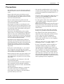
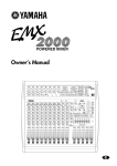
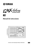
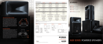
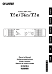
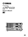
POWERED MIXER
Owner’s Manual
EEEngine
2
1
3
HIGH
HIGH
–15
+15
+15
MID
MID
4
HIGH
–15
5
HIGH
–15
+15
MID
6
HIGH
–15
+15
HIGH
–15
+15
MID
MID
VO. ECHO 1
–15
+15
VO. ECHO 2
MID
VO. REV. 1
125
–15
+15
–15
+15
LOW
LOW
–15
+15
LOW
–15
+15
LOW
–15
+15
–15
+15
+6
+3
0
–5
–10
+12
•
6
•
0
•
6
•
–12
+12
•
6
•
0
•
6
•
–12
250
500
1k
2k
4k
POWER
ON
OFF
PHANTOM
8k
VO. REV. 2
LOW
LOW
HALL. 1
0
–15
+15
–15
+15
MONI
MONI
–15
+15
MONI
–15
+15
MONI
–15
+15
MONI
–15
+15
10
0
EFFECT RTN
10
0
TAPE IN
10
0
10
EFFECT
0
10
EFFECT
0
10
EFFECT
0
10
EFFECT
0
10
EFFECT
PLATE
0
10
LEVEL
0
10
0
10
LEVEL
LEVEL
0
10
LEVEL
0
10
0
10
10
PAD
0
10
PAD
0
10
ON
LEVEL
LEVEL
PAD
0
10
0
10
0
+6
+3
0
–5
–10
+12
•
6
•
0
•
6
•
–12
+12
•
6
•
0
•
6
•
–12
125
0
2 AMPs
300W
300W
MONITOR
ROOM
0
EFFECT
10
MASTER
HALL. 2
MONI
250
500
1k
2k
4k
1
2
LIMITER
MAIN
BRIDGE
8k
MAIN
MAIN
10
0
PAD
10
EFFECT RTN
1
2
3
4
5
6
DIGITAL
EFFECT
Hi-Z
Hi-Z
Hi-Z
Hi-Z
1 LINE 2
1 INST 2
EFFECT OUT
0
10
0
10
TAPE IN
AUX IN
0
MAIN
MONITOR
10
MASTER
MAIN
POWER AMP
MONITOR
TAPE REC
IN
OUT
Lo-Z
Lo-Z
Lo-Z
Lo-Z
MIC
MIC
FOOT SW
AUX IN
SEE REAR PANEL CAUTION
EEEngine
1
1
2
2
INPUT
MAIN
OUTPUT
E
Precautions
1
Precautions
• Do not allow water to enter this unit or allow the
unit to become wet. Fire or electrical shock may
result.
• Connect this unit’s power cord only to an AC
outlet of the type stated in this Owner’s Manual
or as marked on the unit. Failure to do so is a fire
and electrical shock hazard.
• Do not scratch, bend, twist, pull, or heat the
power cord. A damaged power cord is a fire and
electrical shock hazard.
• Do not place heavy objects, including this unit,
on top of the power cord. A damaged power cord
is a fire and electrical shock hazard. In particular,
be careful not to place heavy objects on a power
cord covered by a carpet.
• If you notice any abnormality, such as smoke,
odor, or noise, or if a foreign object or liquid gets
inside the unit, turn it off immediately. Remove
the power cord from the AC outlet. Consult your
dealer for repair. Using the unit in this condition
is a fire and electrical shock hazard.
• Should this unit be dropped or the cabinet be
damaged, turn the power switch off, remove the
power plug from the AC outlet, and contact your
dealer. If you continue using the unit without
heeding this instruction, fire or electrical shock
may result.
• If the power cord is damaged (i.e., cut or a bare
wire is exposed), ask your dealer for a replacement. Using the unit with a damaged power cord
is a fire and electrical shock hazard.
• Do not remove the unit’s cover. You could receive
an electrical shock. If you think internal inspection, maintenance, or repair is necessary, contact
your dealer.
• This unit has ventilation holes at the rear to prevent the internal temperature rising too high. Do
not block them. Blocked ventilation holes are a
fire hazard.
• Clean the contacts of the phone plug before connecting it to the SPEAKERS jack of this unit.
Dirty contacts may generate heat.
• Use only speaker cables when connecting speakers to amplifier outputs. Using other types of
cables is a fire hazard.
Hold the power cord plug when disconnecting it
from an AC outlet. Never pull the cord. A damaged power cord is a potential fire and electrical
shock hazard.
• Do not touch the power plug with wet hands.
Doing so is a potential electrical shock hazard.
• The digital circuits of this unit may induce a
slight noise into nearby radios and TVs. If noise
occurs, relocate the affected equipment.
• Using a mobile telephone near this unit may
induce noise. If noise occurs, use the telephone
away from the unit.
• XLR-type connectors are wired as follows: pin 1:
ground, pin 2: hot (+), and pin 3: cold (-).
• Do not set all equalizer controls and faders to
maximum. Doing so may cause oscillation
depending on the condition of the connected
unit and speakers, and may damage the speakers.
• The performance of components with moving
contacts, such switches, rotary controls, faders,
and connectors, deteriorates over time. The rate
of deterioration depends on the operating environment and is unavoidable. Consult your dealer
about replacing defective components.
• Do not modify the unit. Doing so is a fire and
electrical shock hazard.
• When rack-mounting the unit, allow enough free
space around the unit for normal ventilation.
This should be: 30 cm at the sides, 30 cm behind,
and 40 cm above.
For normal ventilation during use, remove the
rear of the rack or open a ventilation hole.
If the airflow is not adequate, the unit will heat
up inside and may cause a fire.
EMX660—Owner’s Manual
Introduction
3
Introduction
Thank you for purchasing the Yamaha EMX660 Powered Mixer. The EMX660 has the following features.
In order to take full advantage of the EMX660 and enjoy long and trouble-free performance, please read this
owner’s manual carefully, and keep it in a safe place for future reference.
Features
Contents
• The EMX660 provides six input channels compatible with mic/line signals, including highimpedance input suitable for an electric-acoustic
guitar. The EMX660 has ample power, with a
maximum output of 300 W+300 W (600 W with
bridge connection), and is suitable for a wide
range of applications from installed systems to
small-scale PA systems.
Front and rear panel ................................................... 4
Control panel ........................................................ 4
Input/output panel ................................................. 8
Rear panel .......................................................... 10
• A two-channel power amp is built-in. The input
signals for the two channels can be selected as
MAIN+MAIN, MAIN+MONITOR, or MAIN
(bridge connection).
Basic Operation ........................................................ 13
Connecting microphones and instruments ......... 13
Monitoring ........................................................... 13
Using the digital effect ........................................ 13
• Independent 7-band graphic EQ is provided for
both the MONITOR section and the MAIN section. This allows the volume and frequency
response to be adjusted separately for the main
speakers and monitor speakers.
Example setups ........................................................ 14
As a conference PA system/installed
sound system ..................................................... 14
As a band PA ...................................................... 15
• The power amp section has a limiter circuit to
prevent sound distortion and protect the speakers.
Specifications ........................................................... 18
General specifications ........................................ 18
Input specifications .............................................. 19
Output specifications .......................................... 19
Dimensions.......................................................... 20
Block and Level diagram ..................................... 21
• A digital effect with eight selectable effect types is
built-in.
A variety of effects can be applied to add reverberation or ambiance to vocals or instrumental
sounds.
Installation/Connection ............................................. 11
Installation .......................................................... 11
Connection ......................................................... 11
Troubleshooting ....................................................... 17
EMX660—Owner’s Manual
4
Front and rear panel
Front and rear panel
Control panel
■ Channel section
In this section, you can adjust equalization (frequency response), volume level, effect and monitor output levels for the input signal of each
channel.
1
HIGH
–15
1
–15
+15
LOW
–15
+15
MONI
2
0
10
EFFECT
3
0
10
LEVEL
4
0
10
PAD
1
1 Equalizer controls (HIGH, MID, LOW)
This is a 3-band equalizer that adjusts the high
frequency range, mid frequency range, and low
frequency range of each channel. Response is flat
when the knobs are in the ▼ position. Rotating it
toward the right will boost the corresponding frequency band, and rotating it toward the left will
cut it.
The base frequency (or center frequency), range
of boost or cut, and equalizer type of each band
are as follows.
HIGH: 12 kHz ±15 dB shelving type
MID:
2.5 kHz ±15 dB peaking type
LOW:
80 Hz ±15 dB shelving type
EMX660—Owner’s Manual
For each channel, this controls the amount of signal that is sent to the MONITOR bus.
The signal of the MONITOR bus is sent to the
speakers connected to the POWER AMP 2 A/B
jacks (only if the power amp select switch is in the
MAIN-MONITOR position) and to the MONITOR jacks (input/output panel 6).
+15
MID
5
2 Monitor controls (MONI)
Note: The signal is sent to the MONITOR bus
from a location before the level control (4) of
each channel. This means that it will not be affected by the setting of the LEVEL control.
3 Effect control (EFFECT)
For each channel, this controls the amount of signal that is sent to the EFFECT bus.
The signal of the EFFECT bus is sent to the builtin effect and to the EFFECT OUT jacks (input/
output panel 3).
Note: The signal is sent to the EFFECT bus
from a location after the level control (4) of
each channel. This means that the amount of
signal that is sent to the EFFECT bus will be affected not only by the setting of the effect control, but also by the setting of the level control.
4 Level control (LEVEL)
This adjusts the output level for each channel.
5 Pad switch (PAD) (Channel 1–4 only)
This switch attenuates the input signal by 30 dB.
When connecting a line level device to channels
1–4, or if the mic input is distorted, turn this
switch on (the pressed-in position).
5
Control panel
■ DIGITAL EFFECT section
■ MONITOR section
This section allows you to turn the built-in digital
effect on/off and to select the effect type.
This section allows you to adjust the tone and
volume of the MONITOR bus, and specify the
mix level of the built-in effect and the external
input signals.
8
VO. ECHO 1
VO. ECHO 2
VO. REV. 1
VO. REV. 2
HALL. 1
6
125
250
500
1k
9
HALL. 2
2k
4k
B
8k
A
0
0
10
0
EFFECT RTN
ROOM
+6
+3
0
–5
–10
+12
•
6
•
0
•
6
•
–12
+12
•
6
•
0
•
6
•
–12
10
TAPE IN
0
10
MASTER
MONITOR
PLATE
8 Graphic equalizer
ON
7
DIGITAL
EFFECT
6 Effect select switch and indicator
Select the effect type for the built-in digital effect.
The indicator of the selected effect type lights up.
7 DIGITAL EFFECT ON switch and indicator
When this switch is on (pressed), the indicator
lights up and the built-in digital effect can be
used. In that case, the signal processed by the digital effect will be sent to the MAIN/MONITOR
bus. The mix level of the effect sound is adjusted
by the EFFECT RTN control of the MAIN and
MONITOR sections.
This is a 7-band graphic equalizer that allows you
to adjust the frequency response of the MONITOR bus signal, providing a maximum of ±12 dB
of cut/boost for each frequency band. You can use
these sliders to reduce the level of frequency
bands at which feedback easily occurs. Frequency
response is flat when a slider is in the center position. Moving a slider in the positive direction will
boost, and in the negative direction will cut.
This graphic equalizer affects both the MONITOR bus signal that is output to the speakers and
the line level signal which is output from the
MONITOR jack (input/output panel 6).
9 EFFECT RTN control
This controls the level of the effect sound which
is returned from the built-in digital effect to the
MONITOR bus.
0 TAPE IN control
This controls the level of the signal routed from
the TAPE IN jack to the MONITOR bus.
A MASTER control
This adjusts the final level of the MONITOR bus.
It affects both the MONITOR bus signal which is
output to the speakers and the line level signal
which is output to the MONITOR jack (input/
output panel 6).
B Peak level indicator
This indicator allows you to monitor the level of
the signal which is output from the MONITOR
jack (input/output panel 6).
Note: To avoid distortion, adjust the MASTER
control (A) so that the 0 indicator lights occasionally.
EMX660—Owner’s Manual
6
Front and rear panel
■ MAIN section
■ POWER AMP section
This section allows you to adjust the tone and
volume of the MAIN bus, the mix level of the
built-in effect, and the mix level of the external
input.
C
125
250
500
1k
2k
4k
2AMPs
300W
300W
+6
+3
0
–5
–10
+12
•
6
•
0
•
6
•
–12
+12
•
6
•
0
•
6
•
–12
H
0
10
0
10
0
2
10
0
10
MAIN
BRIDGE
MAIN
MAIN
MAIN
MONITOR
MASTER
MAIN
D
E
J
F
C Graphic equalizer
This is a 7-band graphic equalizer that allows you
to adjust the frequency response of the MAIN
bus signal, providing a maximum of ±12 dB of
cut/boost for each frequency band.
This graphic equalizer affects both the MAIN bus
signal that is output to the speakers and the line
level signal which is output from the MAIN jack
(input/output panel 6).
D EFFECT RTN control
This adjusts the level of the effect signal which is
returned from the built-in digital effect to the
MAIN bus.
E AUX IN control
This adjusts the amount of signal that is sent
from the AUX IN jack to the MAIN bus.
F TAPE IN
This adjusts the amount of signal that is sent
from the TAPE IN jacks to the MAIN bus.
G MASTER control
This adjusts the final level of the MAIN bus. It
affects both the MAIN bus signal which is output
from the speakers, and the line level signal which
is output from the MAIN jack (input/output
panel 6).
H Peak level indicator
This indicator allows you to monitor the level of
the signal which is output from the MAIN jack
(input/output panel 6).
Note: To avoid distortion, adjust the MASTER
control (G) so that the 0 indicator lights occasionally.
EMX660—Owner’s Manual
I
8k
TAPE IN
AUX IN
1
LIMITER
G
EFFECT RTN
This section allows you to select the signals that
will be output from the built-in two-channel
power amplifier, and to select the BRIDGE mode.
POWER AMP
I LIMITER indicator
This indicator lights up when the level of the signal output from the power amp section reaches
the maximum and the limiter is activated. Adjust
appropriate control so that the indicator lights up
for only a short while when the signal reaches the
maximum level.
Note: The indicator lights up or flashes for a
longer duration if the power amp section is significantly overloaded, which could result in
malfunction. Avoid such a situation.
J Power amp select switch
Select one of the following three settings to specify the signals that will be output from power
amp 1/2.
• MAIN BRIDGE
With this setting, the MAIN bus signal will be
output from the BRIDGE jack. The two power
amp channels (A and B) will be bridge connected. Only the MASTER control G in the
MAIN section becomes effective.
• MAIN-MAIN
With this setting, the MAIN bus signal will be
output from the POWER AMP 1 A/B jacks and
from the POWER AMP 2 A/B jacks. Only the
MASTER control G in the MAIN section
becomes effective.
• MAIN-MONITOR
With this setting, the MAIN bus signal will be
output from the POWER AMP 1 A/B jacks and
the MONITOR bus signal is output from the
POWER AMP 2 A/B jacks. Only the MASTER
controls in the MAIN and MONITOR sections
G, A are both effective.
Control panel
7
■ POWER indicator & PHANTOM
switch
K
POWER
ON
OFF
PHANTOM
L
K POWER indicator
This indicator will light when the power of the
EMX660 is turned on.
L PHANTOM switch
This switch turns the phantom power supply on/
off for the Lo-Z input jacks of channels 1–4 and
MIC input jacks of channels 5–6.
Turn this switch off if you do not use it.
EMX660—Owner’s Manual
8
Front and rear panel
Input/output panel
Hi-Z
Hi-Z
Hi-Z
Hi-Z
1 LINE 2
1 INST 2
Lo-Z
Lo-Z
Lo-Z
Lo-Z
MIC
MIC
EFFECT OUT
MONITOR
TAPE REC
IN
OUT
FOOT SW
AUX IN
SEE REAR PANEL CAUTION
1
2
3 4
1 Hi-Z, Lo-Z input jacks
Hi-Z jacks
(TRS phone jacks)
Pin 1: ground
Sleeve: ground
Pin 2: hot (+)
Tip: hot (+)
Pin 3: cold (–)
Ring: cold (–)
S
+ - GND
R T
GND -
2
2
INPUT
MAIN
OUTPUT
5
6
These are the input jacks for channels 5–6.
Microphones can be connected to the MIC jacks,
and stereo line level devices (such as synthesizers
or rhythm boxes) can be connected to the LINE
jacks.
The MIC jacks are balanced, and are compatible
with microphones of output impedance 50–
600Ω.
The LINE 1 & 2 jacks are unbalanced, and are
compatible with line level devices of 600Ω output
impedance. These two input jacks can be used
simultaneously.
Nominal input level is –50 dB for the MIC jacks
and –10 dB for the LINE jacks.
INST 1 & 2 jacks are unbalanced, can be used
simultaneously, and their high input impedance
makes them ideal for use with instruments such
as electric-acoustic guitar and electric bass. They
can also be used with line-level sources, such as
synthesizers and drum machines. Nominal input
level is –30 dB.
Note: It is possible to simultaneously use both
the MIC and LINE inputs for channel 5, and the
MIC and INST inputs for channel 6.
+
Note: It is not possible to simultaneously use
both the Hi-Z and Lo-Z inputs of a given channel. For each channel, use only one of the inputs
as appropriate for the input source.
Phantom power is switched on/off in simultaneously for the Lo-Z jacks of channels 1–4 and
the MIC jacks of channels 5–6. For this reason,
any devices other than condenser microphones
must be connected to the Hi-Z or LINE jacks if
the PHANTOM switch (control panel L) is on.
EMX660—Owner’s Manual
1
2 MIC, LINE, INST input jacks
These are the input jacks for channels 1–4. By
using the PAD switches (control panel 5) you
can connect any of the jacks to a wide range of
sources from mics to line level devices (synthesizers or rhythm boxes etc.). The Lo-Z jacks can
provide +15 V phantom power, allowing you to
use condenser microphones.
Both Hi-Z and Lo-Z are balanced, and are compatible with microphones of output impedance
50–600Ω or line level devices of 600Ω. The nominal input level is –40 dB – –10 dB for the Hi-Z
jacks, and –50 dB – –20 dB for the Lo-Z jacks.
Pin connections for the Hi-Z and Lo-Z jacks are
as follows.
Lo-Z jacks
(XLR type)
EEEngine
1
3 Effect output jack (EFFECT OUT)
The input of an external effect such as a delay or
echo can be connected to this jack.
The signal adjusted by the EFFECT control of
each channel will be sent to the EFFECT bus, and
output from this jack.
The nominal output level and impedance are
+4 dB/10 kΩ.
4 Foot switch jack (FOOT SW)
A separately sold Yamaha FC5 foot switch can be
connected to this jack. If a foot switch is connected to this jack, you can use your foot to
switch the built-in digital effect on/off.
Input/output panel
9
5 External input jacks (AUX IN/TAPE IN)
These are input jacks that allow the signal from
an external device to be added to the MAIN output. Monaural output devices such as external
effects can be connected to the AUX IN jack, and
stereo output devices such as cassette recorder or
CD players can be connected to the TAPE IN
jacks.
The nominal input level and impedance are –10 dB/
600Ω for the AUX IN jack, and –10 dBV/600Ω for
the TAPE IN jacks.
6 External output jacks (REC OUT/MONITOR/MAIN)
These are output jacks which send line level signals from the EMX660 to external devices.
A stereo recording device such as a cassette deck,
DAT or MD recorder can be connected to the
REC OUT jacks, and a playback device such a
power amp can be connected to the MONITOR
and MAIN jacks. The signals sent from each jack
are as follows.
• REC OUT jacks: The MAIN bus signal before it
has passed through the MASTER control and
graphic equalizer
• MONITOR jack: The MONITOR bus signal
which has passed through the Monitor MASTER
control and graphic equalizer
• MAIN jack: The MAIN bus signal which has
passed through the Main MASTER control and
graphic equalizer
The nominal output level and impedance are
–10 dBV/10 kΩ for the REC OUT jacks, and
+4 dB/10 kΩ for the MONITOR/MAIN jacks.
EMX660—Owner’s Manual
10
Front and rear panel
Rear panel
2
POWER
ON /
OFF
1 Speaker output jacks (POWER AMP 1 A/B,
POWER AMP 2 A/B, BRIDGE)
Speakers can be connected to these jacks. The
EMX660 contains a two-channel power amp, and
there are three ways in which the speakers can be
connected to the EMX660.
At this time, use the power amp select switch J
on the control panel to select a signal sent to the
correct jacks.
■ When the power amp select switch is set to
MAIN-MONITOR or MAIN-MAIN:
• Two-channel connection
Two 4–8Ω speakers can be connected to the A
jack or B jack of the POWER AMP 1/2 (maximum output 300W+300W).
• Two-channel parallel connection
Two 8–16Ω speakers can be connected to the
POWER AMP 1 A/B jacks and two more to the
POWER AMP 2 A/B jacks, for a total of four
speakers (maximum output 300 W+300 W).
■ When the power amp select switch is set to
MAIN-BRIDGE (Bridge connection)
• One 8–16Ω speaker can be connected to the
BRIDGE jack (maximum output 600 W).
EMX660—Owner’s Manual
1
B
A
POWER AMP 2
SPEAKERS
BRIDGE
B
A
POWER AMP 1
Caution:
When using a bridge connection, do not connect anything to the POWER AMP 1 and POWER AMP 2 jacks. Likewise, when using the
POWER AMP 1 and/or POWER AMP 2 jacks,
do not connect anything to the BRIDGE jack.
2 Power switch
This switch turns the power of the EMX660 on/
off.
Note: Before turning the EMX660 on/off, turn
down the MASTER controls of the MONITOR
and MAIN section.
Installation/Connection
11
Installation/Connection
Installation
The EMX660 uses a forced cooling system with intake on the bottom of the rear panel and exhaust on the top
of the rear panel to avoid blocking the heated air flow.
Front
30cm
or less
NO
NO
Exhaust
Front
Intake
Connection
When connecting various devices, be sure to use cables and plugs of the appropriate standard.
■ Speaker connection
There are three ways in which speakers can be connected to the EMX660.
1 Two-channel connection — A single speaker each can be connected to either the A or the B jack of POWER
AMP 1 and of POWER AMP 2.
2 Two-channel parallel connection — Two speakers can be connected in parallel to both the A and B jacks of
POWER AMP 1 and of POWER AMP 2.
3 Bridge connection — A single speaker can be connected to the BRIDGE jack.
For each of these, the required speaker impedance will differ. Refer to the following diagram, and make sure
that the speaker impedance is not less than the specified value.
Two-channel connection
MAIN
BRIDGE
MAIN
MAIN
MAIN
MONITOR
Two-channel parallel connection
B
SPEAKERS
A
B
No
A
B
A
connection
POWER AMP 2
SPEAKERS
No
B
A
connection
POWER AMP 1
BRIDGE
POWER AMP 2
BRIDGE
POWER AMP 1
or
MAIN
BRIDGE
MAIN
MAIN
MAIN
MONITOR
4Ω~8Ω
4Ω~8Ω
Main/Monitor
Speaker
Main
Speaker
8Ω~16Ω 8Ω~16Ω
Main/Monitor
Speakers
8Ω~16Ω 8Ω~16Ω
Main
Speakers
Bridge connection
MAIN
BRIDGE
MAIN
MAIN
MAIN
MONITOR
B
No
SPEAKERS
A
connection
POWER AMP 2
B
No
A
connection
BRIDGE
POWER AMP 1
8Ω~16Ω
Main Speaker
EMX660—Owner’s Manual
12
Installation/Connection
■ Example connections
Recorder (Cassette, DAT, MD)
CD player
Effects processor
88
Synthesizer,
Drum machine,
Guitar processor
Monitors Speakers
Power AMP
Hi-Z
Hi-Z
Hi-Z
Hi-Z
1 LINE 2
1 INST 2
Lo-Z
Lo-Z
Lo-Z
Lo-Z
MIC
MIC
EFFECT OUT
MONITOR
TAPE REC
IN
OUT
FOOT SW
AUX IN
SEE REAR PANEL CAUTION
EEEngine
1
1
2
2
INPUT
MAIN
OUTPUT
*1
Footswitch
(YAMAHA FC5)
Microphone
Main Speakers
Electric-acoustic
guitar
Electric bass
The figure above shows appropriate jacks to
connect each instrument.
* The Lo-Z and Hi-Z input of each channel cannot
be used simultaneously.
*1. Although this example shows an external effects
processor and footswitch, which is used to turn
on and off the built-in digital effects processor,
connected to the EMX660, in practice, only one
effects processor, internal or external, will be
used at a time, so the footswitch is not required
when using external effects.
EMX660—Owner’s Manual
Normally, connect speakers to the
jacks on the rear panel. If more
speaker outputs are needed, use the
MAIN (STEREO) jacks for stereo
output and the MONITOR jack for
monaural output.
Basic Operation
13
Basic Operation
This section explains basic operation of the EMX660.
Connecting microphones
and instruments
1 Before connecting mics or instruments,
make sure that the power of all equipment (where applicable) is turned off.
Also make sure that the level controls of
each channel of the EMX660 and the
MASTER control of the MAIN section are
turned down.
2 Connect cables to your mics and instruments, and insert the other end of the
cable firmly into the appropriate Lo-Z/HiZ jack (channels 1–4) or the MIC jack
(channels 5–6), LINE jack (channels 5),
INST jack (channels 6).
Note: When connecting a line level device to
channels 1–4, turn on the PAD switch.
You cannot use a channel’s Lo-Z and Hi-Z jacks
at the same time. The MIC and LINE jacks, or
the MIC and INST jacks, however, can be used
at the same time.
3 Turn the power on in the order of peripheral devices ➞ EMX660.
Note: When turning the power off, reverse this
sequence.
4 Set the MAIN section MASTER control to
the √ position.
5 While speaking into the mic (while playing the instrument), adjust the channel
LEVEL control so that the 0 LED of the
MAIN section peak level meter lights
occasionally.
Repeat this step for each channel.
6 If you wish to adjust the tone of each
channel, rotate the equalizer controls as
desired.
7 Use the MAIN section graphic equalizer
to adjust the tone.
8 Use the MAIN MASTER control to adjust
the overall volume.
Monitoring
By connecting a powered monitor speaker to the
MONITOR OUTPUT, you can create a monitor
mix independent of the MAIN mix, since the
input channel MONI controls are not affected by
the LEVEL controls.
1 Set the MONI MASTER control to the √
position.
2 While speaking into a connected mic, or
playing a connected instrument, adjust
the MONI control of the input channel
that you want to monitor.
Repeat this procedure for each channel.
3 Use the MONI MASTER control to set the
overall level of the monitor mix.
Using the digital effect
The EMX660 has a built-in digital effect, allowing reverberation or ambiance to be added to
vocals or instrumental sounds.
1 Press the DIGITAL EFFECT ON switch of
the DIGITAL EFFECT section.
2 Use the effect select switches of the DIGITAL EFFECT section to select the effect
type.
VO.ECHO 1, 2 .....Echo appropriate for vocals.
VO.REV. 1, 2........Reverb appropriate for vocals.
HALL 1, 2 .............Reverb typical of a hall.
ROOM ..................Reverb typical of a room.
PLATE .................Plate echo-like reverberation
3 Set the MAIN EFFECT RTN control to the
√ position.
4 Raise the EFFECT control of the channels
to which you wish to apply the digital
effect.
5 Use the MAIN/MONITOR section EFFECT
RTN control to adjust the level of the
sound processed by the effect.
Note: If the effect sound is distorted even if the
EFFECT RTN turned all the way down, lower
the EFFECT controls of each channel.
EMX660—Owner’s Manual
14
Example setups
Example setups
This section provides some ways in which the EMX660 can be used, and explains connections and operation.
As a conference PA system/installed sound system
Here is an example of using the EMX660 as a conference PA system or as an installed sound system.
Main Speakers
Power AMP 1 A/B
2
1
3
HIGH
HIGH
–15
+15
–15
+15
MID
MID
4
HIGH
–15
+15
MID
Power AMP 2 A/B
5
HIGH
6
HIGH
–15
+15
HIGH
–15
+15
MID
MID
VO. ECHO 1
–15
VO. ECHO 2
+15
MID
VO. REV. 1
125
–15
+15
–15
+15
LOW
LOW
–15
+15
LOW
–15
+15
LOW
–15
+15
–15
+15
+6
+12
•
6
•
0
•
6
•
–12
+12
•
6
•
0
•
6
•
–12
250
500
1k
2k
4k
POWER
+3
0
ON
OFF
–5
–10
PHANTOM
8k
VO. REV. 2
LOW
LOW
HALL. 1
0
–15
+15
–15
+15
MONI
MONI
–15
+15
MONI
–15
+15
MONI
–15
+15
MONI
–15
+15
10
0
EFFECT RTN
10
0
TAPE IN
0
10
0
10
EFFECT
0
10
EFFECT
0
10
EFFECT
0
10
EFFECT
0
10
EFFECT
PLATE
0
10
LEVEL
0
10
0
10
LEVEL
LEVEL
0
10
LEVEL
0
10
0
10
ON
LEVEL
LEVEL
0
10
0
10
PAD
0
10
PAD
0
10
0
10
0
+6
+3
0
–5
+12
•
6
•
0
•
6
•
–12
+12
•
6
•
0
•
6
•
–12
125
PAD
2 AMPs
300W
300W
MONITOR
ROOM
EFFECT
10
MASTER
HALL. 2
MONI
250
500
1k
2k
4k
1
2
LIMITER
–10
10
0
10
EFFECT RTN
1
2
3
4
5
6
DIGITAL
EFFECT
Hi-Z
Hi-Z
Hi-Z
Hi-Z
1 LINE 2
1 INST 2
EFFECT OUT
0
10
0
10
TAPE IN
AUX IN
0
MAIN
MONITOR
Lo-Z
Lo-Z
Lo-Z
MIC
MIC
MAIN
POWER AMP
AUX IN
SEE REAR PANEL CAUTION
Connections
• Connect mics to channel inputs 1–6.
• If you wish to use an external device such as a CD
player or LD player, connect the outputs of the
device to the TAPE IN jacks of the EMX660.
Note: A CD/LD player or cassette deck can also
be connected to the LINE jacks of channel 5.
• If you wish to record the audio to a cassette deck,
connect the REC OUT jacks of the EMX660 to
the input jacks of the cassette deck.
• Connect the main speakers to the A/B jacks of the
POWER AMP 1/2, and set the power amp select
switch to "MAIN-MAIN."
EMX660—Owner’s Manual
MAIN
MONITOR
MONITOR
FOOT SW
Microphone
MAIN
MAIN
10
MASTER
TAPE REC
IN
OUT
Lo-Z
MAIN
BRIDGE
MAIN
BRIDGE
8k
MAIN
MAIN
PAD
Power amp
select switch
CD Player
EEEngine
1
1
2
2
INPUT
MAIN
OUTPUT
Cassette Deck
Playing back a CD player
1 Turn the power on in the order of peripheral devices ➞ EMX660.
2 Adjust the MASTER control of the MAIN
section to the √ position.
3 Start playback on the CD player, and use
the MAIN section TAPE IN control to
adjust the level so that the 0 LED of the
MAIN section peak level meter does not
light.
As a band PA
15
As a band PA
Here is an example of using the EMX660 as a small PA for a band. In this example, the monitor speakers are
being sent a mix that is independent of the MAIN speaker mix. An external effect such as delay or reverb is
also being used.
Connections
Note: Set the power amp select switch of the POWER AMP section to the “MAIN MONITOR” position. If you are using an external effect, we
recommend that you turn down the EFFECT RTN
controls of the MAIN and MONITOR sections. If
the external effect has a stereo output, it is possible
to connect its output jacks to the LINE jacks of
channels 5. However in this case, be sure that the
EFFECT controls are turned all the way down for
the channels into which the effect sound is being input. If the EFFECT controls are raised, feedback will
occur, and your speakers may be damaged.
• Connect mics or instruments, such as keyboards,
to the channel input jacks 1–6.
• Connect the main speakers to the POWER AMP
1 A/B jacks, and connect the monitor speakers to
the POWER AMP 2 A/B jacks.
• If you will be using an external effect such as
delay or reverb, connect the EMX660’s EFFECT
OUT jack to the input jack of the external effect,
and connect the output jack of the external effect
to the EMX660’s AUX IN jack.
Main Speakers
Monitors Speakers
A
3
HIGH
–15
+15
4
HIGH
–15
+15
MID
MID
B
Power AMP 1
2
1
HIGH
–15
+15
MID
+15
HIGH
–15
+15
MID
MID
VO. ECHO 1
–15
+15
VO. ECHO 2
MID
VO. REV. 1
+15
–15
+15
LOW
–15
+15
LOW
–15
+15
LOW
–15
+15
–15
+15
+6
+3
0
–5
–10
+12
•
6
•
0
•
6
•
–12
+12
•
6
•
0
•
6
•
–12
125
–15
LOW
B
Power AMP 2
6
HIGH
–15
A
5
HIGH
250
500
1k
2k
4k
POWER
ON
OFF
PHANTOM
8k
VO. REV. 2
LOW
LOW
HALL. 1
0
–15
+15
–15
+15
MONI
MONI
–15
+15
MONI
–15
+15
MONI
–15
+15
MONI
–15
+15
10
0
EFFECT RTN
10
0
TAPE IN
10
MASTER
MONITOR
ROOM
0
10
0
10
EFFECT
EFFECT
0
10
EFFECT
0
10
EFFECT
0
10
EFFECT
0
10
EFFECT
PLATE
0
10
LEVEL
0
10
0
10
LEVEL
LEVEL
0
10
LEVEL
0
10
0
10
ON
LEVEL
LEVEL
0
10
0
10
PAD
0
10
PAD
0
10
0
10
0
+6
+3
0
–5
–10
+12
•
6
•
0
•
6
•
–12
+12
•
6
•
0
•
6
•
–12
125
PAD
2 AMPs
300W
300W
HALL. 2
MONI
250
500
1k
2k
4k
1
2
LIMITER
MAIN
BRIDGE
8k
MAIN
MAIN
10
0
PAD
10
EFFECT RTN
1
2
3
4
5
6
DIGITAL
EFFECT
Hi-Z
Hi-Z
Hi-Z
Hi-Z
1 LINE 2
1 INST 2
EFFECT OUT
0
10
0
10
TAPE IN
AUX IN
0
MAIN
MONITOR
Lo-Z
Lo-Z
Lo-Z
MIC
MIC
MAIN
BRIDGE
MAIN
MAIN
MAIN
MONITOR
10
MASTER
MAIN
POWER AMP
MONITOR
TAPE REC
IN
OUT
Lo-Z
Power amp
select switch
FOOT SW
AUX IN
EEEngine
SEE REAR PANEL CAUTION
Microphone
1
1
2
2
INPUT
MAIN
OUTPUT
88
Effects Processor
*1
Keyboard 1
Electric
bass
Electric-acoustic
guitar
*1. Although this example shows an
external effects processor and footswitch, which is used to turn on and
Footswitch
off the built-in digital effects process(YAMAHA FC5)
or, connected to the EMX660, in
practice, only one effects processor,
internal or external, will be used at a
time, so the footswitch is not required
when using external effects.
EMX660—Owner’s Manual
16
Example setups
Sending an independent mix to the
monitor speakers
1 Set the MONITOR section MASTER control to the √ position.
2 Raise the MONI controls for the channels
that you wish to hear from the monitor
speakers.
Note: The MONI controls are not affected by
the level settings of each channel. This allows
you to create a mix that is independent of the
MAIN section.
3 Use the graphic equalizers and MASTER
controls of the MAIN/MONITOR sections
to adjust the overall volume and tone.
EMX660—Owner’s Manual
Using an external effect
1 Raise the EFFECT controls for the channels
to which you want the external effect to
be applied.
2 Adjust the input level of the external
effect so that the sound is not distorted at
the input of the external effect.
3 Use the MAIN section AUX IN control to
adjust the level of the sound processed by
the effect.
Troubleshooting
17
Troubleshooting
The following table describes the possible malfunctions of this device, and the appropriate actions to be taken in
each case.
Problem
The POWER
indicator is
dark.
Cause
Action
Please wait. When the device cools off, normal
operation will resume automatically. However,
please check the following two points to prevent the
The load on this device was too great,
and the protection circuit for the inter- problem from recurring.
If the input to this device is greater than the nominal
nal transformer has operated. Possilevel, lower the input to the nominal level. If the
ble reasons for the excessive load are
an excessive input to the device, or inap- device is not ventilated sufficiently, refer to the cautions given at the beginning of this manual and take
propriate ventilation.
appropriate measures to insure adequate ventilation.
Please wait. When the device cools off, normal
operation will resume automatically. However,
please check the following three points to prevent
Sound is no
The load on the amplifier of this device the problem from recurring.
longer outIf the level setting is excessive, lower it to the nomiwas too great, and the protection cirput from the
nal level. You can refer to the peak level indicators
cuit for the amplifier has operated.
speakers.
Possible reasons for the excessive load of the main section when doing so.
The POWER
If the device is not ventilated sufficiently, refer to the
are an excessive level setting in the
indicator is lit.
channel control section or main section, cautions given at the beginning of this manual and
take appropriate measures to insure adequate veninsufficient ventilation, or insufficient
load impedance of the connected speak- tilation.
If the load impedance (including a short) is too low,
ers.
refer to the chapter on connections (page 11) and
change the connections so that the impedance is
correct.
Connections between devices have
come loose.
Inspect the connections, and correct any faulty connections.
Other
The device may have malfunctioned. Please contact your dealer.
Other
EMX660—Owner’s Manual
18
Specifications
Specifications
■ General specifications
Maximum output power
300 W + 300 W/4Ω @0.5% THD at 1 kHz (POWER AMP OUT 1, 2)
215 W + 215 W/8Ω @0.5% THD at 1 kHz (POWER AMP OUT 1, 2)
600 W/8Ω @0.5% THD at 1 kHz (BRIDGE)
Frequency response
20 Hz~20 kHz +1 dB, –3 dB @1 W output into 8Ω (POWER AMP OUT)
20 Hz~20 kHz +1 dB, –3 dB @+4 dB output into 10 kΩ (MAIN OUT, MONITOR OUT, EFFECT SEND)
Total harmonic distortion
Less than 0.5% @20 Hz~20 kHz, 150 W output into 4Ω (POWER AMP OUT 1, 2)
Less than 0.3% @20 Hz~20 kHz, +14 dB output into 10 kΩ (MAIN OUT, MONITOR OUT, EFFECT OUT)
–124 dB equivalent input noise, –65 dB residual output noise (POWER AMP OUT)
–88 dB residual output noise (MAIN OUT, MONITOR OUT)
Hum & noise
(Average, Rs=150Ω)
(with 20 Hz~20 kHz BPF)
–79 dB (83 dB S/N)
MAIN OUT, MONITOR OUT
Master level control at nominal level and all channel
level controls at minimum.
–69 dB (73 dB S/N)
MAIN OUT, MONITOR OUT
Master level control at nominal level and 1 channel
level control at nominal level.
–75 dB (79 dB S/N)
EFFECT SEND
Master level control at nominal level and all channel
level controls at minimum.
–69 dB (73 dB S/N)
EFFECT SEND
Master level control at nominal level and 1 channel
level control at nominal level.
Maximum voltage gain
(PAD: OFF)
88 dB CH IN (Lo-Z) to POWER AMP OUT (CH1~4)
66 dB CH IN (Lo-Z) to MAIN OUT, MONITOR OUT (CH1~4)
72 dB CH IN (Lo-Z) to EFFECT OUT (CH1~4)
48 dB CH IN (Lo-Z) to REC OUT (CH1~4)
56 dB CH IN (Hi-Z) to MAIN OUT, MONITOR OUT (CH1~4)
26 dB AUX IN to MAIN OUT
24 dB TAPE IN to MAIN OUT
66 dB MIC IN to MAIN OUT, MONITOR OUT (CH5•6)
26 dB LINE IN to MAIN OUT, MONITOR OUT (CH5)
46 dB INST IN to MAIN OUT, MONITOR OUT (CH6)
Crosstalk at 1 kHz
65 dB adjacent input, 65 dB input to output
Input channel equalization
±15 dB Maximum
HIGH 12 kHz shelving*
MID
2.5 kHz peaking
LOW 80 Hz shelving*
* Turn over/roll-off frequency of shelving: 3 dB below maximum variable level.
Meters
5 POINTS LED METER (–10, –5, 0, +3, +6 dB) (MAIN OUT, MONITOR OUT)
Graphic equalizer
7 bands (125, 250, 500, 1 k, 2 k, 4 k, 8 kHz), ±12 dB Maximum (MAIN OUT, MONITOR OUT)
Internal digital effect
8 types (VO.ECHO 1, VO.ECHO 2, VO.REV. 1, VO.REV. 2, HALL 1, HALL 2, ROOM, PLATE)
Phantom power
+15 V is supplied to electrically balanced inputs for powering condenser microphones via 2.4 kΩ
current limiting/isolation resisters.
Limiter
Comp. : THD≥0.5% (POWER AMP OUT)
LIMIT indicators
Turns on. : THD≥0.5% (POWER AMP OUT)
Protection Circuit (Power Amp.)
POWER Switch on/off Mute, DC Detection, Temp (Heatsink Temp≥90˚C)
Foot switch (FC-5)
DIGITAL EFFECT MUTE : on/off
Power requirement
USA and Canada
Europe
Other
Power consumption
250 W
Dimensions (WxHxD)
497×275×275 mm
Weight
17 kg
• 0 dB=0.775 Vrms
EMX660—Owner’s Manual
120 V AC 60 Hz
230 V AC 50 Hz
240 V AC 50 Hz
Input specifications
19
■ Input specifications
Input level
Input connectors
CH INPUT (Lo-Z)
(CH1~4)
PAD
Actual load
impedance
Nominal
impedance
3 kΩ
OFF
ON
CH INPUT (Hi-Z)
(CH1~4)
OFF
10 kΩ
Sensitivity1
Nominal level
Max. before
cliping
50~600Ω
Mics
–62 dB (0.616 mV)
–50 dB (2.45 mV)
–20 dB (77.5 mV)
600Ω Lines
–32 dB (19.5 mV)
–20 dB (77.5 mV)
+10 dB (2.45 V)
50~600Ω
Mics
–52 dB (1.95 mV)
–40 dB (7.75 mV)
–10 dB (245 mV)
600Ω Lines
–22 dB (61.6 mV)
–10 dB (245 mV)
+20 dB (7.75 V)
Connector
type
XLR-3-31 type2
Phone jack
(TRS)2
ON
MIC INPUT (CH5•6)
3 kΩ
50~600Ω
Mics
–62 dB (0.616 mV)
–50 dB (2.45 mV)
–20 dB (77.5 mV)
LINE INPUT (CH5) (1, 2)
10 kΩ
600Ω Lines
–22 dB (61.6 mV)
–10 dB (245 mV)
+20 dB (7.75 V)
Phone jack3
INST INPUT (CH6) (1, 2)
470 kΩ
1 kΩ
–42 dB (6.16 mV)
–30 dB (24.5 mV)
0 dB (0.775 V)
Phone jack3
AUX IN
10 kΩ
600Ω Lines
–22 dB (61.6 mV)
–10 dB (245 mV)
+20 dB (7.75 V)
Phone jack3
TAPE IN (1, 2)
10 kΩ
600Ω Lines
XLR-3-31 type2
–22 dBV (79.4 mV) –10 dBV (316 mV) +17.8 dBV (7.76 V)
RCA phono
jack3
1. Sensitivity is the lowest level that can produce an output of +4 dB (1.23 V) or the nominal output level when the unit is set at maximum gain.
(All level controls are at maximum position.)
2. Balanced (T=Hot, R=Cold, S=Gnd)
3. Unbalanced
• 0 dB=0.775 Vrms, 0 dBV=1 Vrms.
■ Output specifications
Actual source
impedance
Nominal
impedance
POWER AMP OUT (1•2) (A, B)
0.1Ω
BRIDGE OUT
Output connectors
Output level
Connector type
Nominal
Max. before cliping
4/8Ω Speaker
60 W/4Ω
(300 W/4Ω)
Phone jack
0.1Ω
8Ω Speaker
120 W/8Ω
(600 W/8Ω)
Phone jack
MAIN OUT
600Ω
10 kΩ Lines
+4 dB (1.23 V)
+20 dB (7.75 V)
Phone jack
MONITOR OUT
600Ω
10 kΩ Lines
+4 dB (1.23 V)
+20 dB (7.75 V)
Phone jack
EFFECT OUT
600Ω
10 kΩ Lines
+4 dB (1.23 V)
+20 dB (7.75 V)
Phone jack
REC OUT (1, 2)
600Ω
10 kΩ Lines
–10 dBV (316 mV)
+10 dBV (3.16 V)
RCA phono jack
• All output jacks are unbalanced.
• 0 dB=0.775 Vrms, 0 dBV=1 Vrms.
Specifications are subject to change without prior notice.
For European Model
Purchaser/User Information specified in EN55103-1 and EN55103-2.
Inrush Current: 56A
Conformed Environment: E1, E2, E3 and E4
EMX660—Owner’s Manual
20
Specifications
■ Dimensions
168
259
(45.5)
H:275
(45.5)
W:497
45.5
380
487
45.5
16
57.5
150
(67.5)
D:275
Unit:mm
EMX660—Owner’s Manual
CH INPUT
(CH6)
CH INPUT
(CH5)
–50dB
–40dB
–30dB
–20dB
–10dB
0dB
+10dB
+20dB
+30dB
+40dB
INST
[–30dB]
MIC
[–50dB]
LINE
[–10dB]
MIC
[–50dB]
2
1
2
1
1
Lo-Z PAD:OFF [–50dB]
MIC (CH5,6) [–50dB]
Hi-Z PAD:OFF [–40dB]
INST (CH6) [–30dB]
Lo-Z PAD:ON [–20dB]
LINE (CH5) [–10dB]
Hi-Z PAD:ON [–10dB]
BA
BA
HA
HA
AUX IN
[–10dB]
TAPE IN
CH5,6 [–22dB]
[0dB]
[–22dB]
[–22dB]
[–16dB]
TAPE IN
AUX IN
ON
LEVEL
DIGITAL EFFECT ON
TAPE IN
Clip Level [+20dB]
[–10dBV (–7.8dB)]
3-Stage EQ
AUX IN
[–10dB]
[–22dB]
BA
[–22dB]
BA
3-Stage EQ
[–10dB]
3-Stage EQ
BA
[–16dB]
[–10dB]
[–10dB]
[–10dB]
[–10dB]
PAD
[30dB]
DIGITAL EFFECT MUTE
FOOT SW
PLATE
ROOM
HALL 2
HALL 1
VO. REV. 2
VO. REV. 1
VO. ECHO 2
VO. ECHO 1
TAPE IN
[–10dBV]
[–7.8dB] 2
AUX IN
[–10dB]
PAD
[10dB]
+15V
[–10dB]
Lo
Lo
Lo
HA
Hi
Hi
Hi
CH INPUT
Hi-Z
(CH1–4)
[–40/–10dB]
ON
Mid
Mid
Mid
Lo-Z
[–50/–20dB]
DIGITAL
EFFECT
EFFECT
[–16dB]
[–16dB]
[–16dB]
[–16dB]
[–16dB]
INV
[0dB]
[0dB]
[–16dB]
SUM
MONI
EFFECT
[–22dB]
MONI
EFFECT
[–22dB]
MONI
EFFECT
[–22dB]
MAIN
EFFECT
MONITOR
MAIN
EFFECT
MONITOR
EFFECT [–22dB]
MAIN,MONITOR[–16dB]
AUX, TAPE [0dB]
EFFECT RETURN
[–6dB]
EFFECT RETURN
[–6dB]
MONITOR
LEVEL
LEVEL
LEVEL
SUM
SUM
SUM
BA
BA
BA
[+4dB]
[+4dB]
[+4dB]
REC OUT [–10dBV] [–7.8dB]
MONI MASTER
[–6dB]
REC OUT
[–10dBV]
2 [–7.8dB]
1
MAIN MASTER
[–6dB]
[–6dB]
[0dB]
[0dB]
7-Stage GEQ
7-Stage GEQ
125Hz
250Hz
500Hz
1kHz
2kHz
4kHz
8kHz
125Hz
250Hz
500Hz
1kHz
2kHz
4kHz
8kHz
PHANTOM
OFF
LIMITER
PA
LIMITER
1
POWER AMP2 OUT
[300W/4Ω]
B
2
1
POWERAMPOUT[60W/4Ω]
–50dB
–40dB
–30dB
–20dB
–10dB
0dB
+10dB
+20dB
+30dB
+40dB
A
1
2
1
BRIDGE OUT
[600W/8Ω]
POWER AMP1 OUT
[300W/4Ω]
B
2
2
A
1
2
MAXIMUM OUTPUT POWER
[300W/4Ω]
EFFECT OUT
[+4dB]
MONITOR OUT
[+4dB]
POWER AMP
MAIN BRIDGE
MAIN/MAIN
MAIN/MONITOR
MAIN OUT
[+4dB]
MONITOR OUT [+4dB]
EFFECT OUT [+4dB]
INV
PA
MAIN OUT
[+4dB]
Block and Level diagram
21
■ Block and Level diagram
EMX660—Owner’s Manual
YAMAHA CORPORATION
V529000 R1 1 IP 24
NP Printed in Taiwan
Pro Audio & Digital Musical Instrument Division
P.O. Box 3, Hamamatsu, 430-8651, Japan