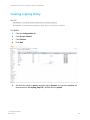
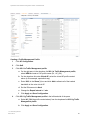
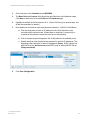
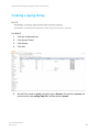
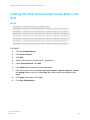
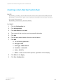
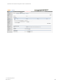
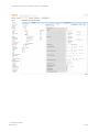
1
Spectralink VIEW Certified Configuration Guide Aruba Networks Aruba Controllers (Series) 600, 3200, 3400, 3600, 6000, 7000, 7100, 7200 Aruba APs AP-60, AP-61, AP-65, AP-68, AP-70, AP-9x, AP-10x, AP-11x, AP-12x, AP-13x, AP-22x, AP-27x 721-1002-000 Rev: AB March 2015 Spectralink VIEW Certified Configuration Guide: Aruba Networks Copyright Notice © 2005-2015 Spectralink Corporation All rights reserved. SpectralinkTM, the Spectralink logo and the names and marks associated with Spectralink’s products are trademarks and/or service marks of Spectralink Corporation and are common law marks in the United States and various other countries. All other trademarks are property of their respective owners. No portion hereof may be reproduced or transmitted in any form or by any means, for any purpose other than the recipient’s personal use, without the express written permission of Spectralink. All rights reserved under the International and pan-American Copyright Conventions. No part of this manual, or the software described herein, may be reproduced or transmitted in any form or by any means, or translated into another language or format, in whole or in part, without the express written permission of Spectralink Corporation. Do not remove (or allow any third party to remove) any product identification, copyright or other notices. Notice Spectralink Corporation has prepared this document for use by Spectralink personnel and customers. The drawings and specifications contained herein are the property of Spectralink and shall be neither reproduced in whole or in part without the prior written approval of Spectralink, nor be implied to grant any license to make, use, or sell equipment manufactured in accordance herewith. Spectralink reserves the right to make changes in specifications and other information contained in this document without prior notice, and the reader should in all cases consult Spectralink to determine whether any such changes have been made. NO REPRESENTATION OR OTHER AFFIRMATION OF FACT CONTAINED IN THIS DOCUMENT INCLUDING BUT NOT LIMITED TO STATEMENTS REGARDING CAPACITY, RESPONSE-TIME PERFORMANCE, SUITABILITY FOR USE, OR PERFORMANCE OF PRODUCTS DESCRIBED HEREIN SHALL BE DEEMED TO BE A WARRANTY BY SPECTRALINK FOR ANY PURPOSE, OR GIVE RISE TO ANY LIABILITY OF SPECTRALINK WHATSOEVER. Contact Information US Location 800-775-5330 European Location +45 7560 2850 Spectralink Corporation 2560 55th Street Boulder, CO 80301 Spectralink Europe ApS Langmarksvej 34 8700 Horsens, Denmark [email protected] [email protected] 721-1002-000_AB.docx March 2015 2 Contents Introduction ...................................................................... 6 Certified Product Summary .............................................................................................. 6 Known Limitations ............................................................................................................ 7 Spectralink References .................................................................................................... 9 Support documents ......................................................................................................... 9 White Papers ..................................................................................................................10 Product Support ..............................................................................................................10 Section 1: Configuration for Wi-Fi Standard QoS ...................... 11 Introduction ......................................................................................................................11 Command, Comment, and Screen Text Key ..................................................................11 Network Topology............................................................................................................12 Connecting to the Mobility Controller ............................................................................13 Via console.....................................................................................................................13 Via the Command Line Interface (CLI) ...........................................................................13 Via the Web interface (WebUI) .......................................................................................13 Initializing the Controller .................................................................................................15 Licensing the Controller ..................................................................................................17 Logical and Physical Interfaces ......................................................................................19 Using CLI .......................................................................................................................19 On the WebUI ................................................................................................................20 Creating Firewall Roles and Policies ..............................................................................23 Creating a Syslog Policy .................................................................................................24 On CLI ............................................................................................................................24 On WebUI ......................................................................................................................24 Creating User-Role and Assigning Firewall Rules to the Role .....................................26 On CLI ............................................................................................................................26 On WebUI ......................................................................................................................26 Creating a User-Role Derivation Rule.............................................................................28 On CLI ............................................................................................................................28 On WebUI ......................................................................................................................28 Configuration Steps for None, WEP, WPA-PSK or WPA2-PSK Security......................30 Creating an Authentication Profile for controller-based authentication ............................30 Use the next four statements if using an external Radius server: ...................................30 Configuration Steps for WPA2-Enterprise Security ......................................................34 Defining an 802.1X authentication server .......................................................................34 Create a Server Group and Add the RADIUS Server .....................................................36 Using CLI .......................................................................................................................36 Using WebUI ..................................................................................................................36 721-1002-000_AB.docx March 2015 3 Spectralink VIEW Certified Configuration Guide: Aruba Networks Creating an 802.1X Authentication Profile .....................................................................37 Using CLI .......................................................................................................................37 Using WebUI ..................................................................................................................37 Creating an Authentication Profile .................................................................................38 Using CLI .......................................................................................................................38 Using WebUI ..................................................................................................................38 Wireless LAN Configuration ...........................................................................................40 On CLI ............................................................................................................................40 On WebUI ......................................................................................................................50 Section 2: Configuration for SVP Operation with Spectralink 8020/8030 Handsets ........................................................... 73 Introduction ......................................................................................................................73 Command, Comment, and Screen Text Key ..................................................................73 Connecting to the Mobility Controller ............................................................................74 Via console.....................................................................................................................74 Via the CLI .....................................................................................................................74 Via the Web interface (WebUI) .......................................................................................74 Initializing the Controller .................................................................................................76 Licensing the Controller ..................................................................................................78 Logical and Physical Interfaces ......................................................................................80 Using CLI .......................................................................................................................80 On the WebUI ................................................................................................................80 Creating Firewall Roles and Policies ..............................................................................84 Creating a Syslog Policy .................................................................................................85 On CLI ............................................................................................................................85 On WebUI ......................................................................................................................85 Creating User-Role and Assigning Firewall Rules to the Role .....................................87 On CLI ............................................................................................................................87 On WebUI ......................................................................................................................87 Creating a User-Role Derivation Rule.............................................................................89 On CLI ............................................................................................................................89 On WebUI ......................................................................................................................89 Configuration Steps for None, WEP, WPA-PSK or WPA2-PSK Security......................91 Creating an Authentication Profile for controller-based authentication ............................91 Configuration Steps for WPA2-Enterprise Security ......................................................95 Defining an 802.1X authentication server .......................................................................95 Create a Server Group and Add the RADIUS Server .....................................................97 Using CLI .......................................................................................................................97 Using WebUI ..................................................................................................................97 Creating an 802.1X Authentication Profile .....................................................................98 Using CLI .......................................................................................................................98 Using WebUI ..................................................................................................................98 721-1002-000_AB.docx March 2015 4 Spectralink VIEW Certified Configuration Guide: Aruba Networks Creating an Authentication Profile ...............................................................................100 Using CLI .....................................................................................................................100 Using WebUI ................................................................................................................100 Wireless LAN Configuration .........................................................................................102 On CLI ..........................................................................................................................102 On WebUI ....................................................................................................................107 721-1002-000_AB.docx March 2015 5 Introduction Spectralink’s Voice Interoperability for Enterprise Wireless (VIEW) Certification Program is designed to ensure interoperability and high performance between Spectralink 84-Series, 87Series, and 8020/8030 Wireless Telephones and WLAN infrastructure products. The products listed below have been tested in Spectralink’s lab and have passed VIEW Certification. Certified Product Summary Manufacturer: Aruba Networks: www.arubanetworks.com Certified products: Controllers (Series): Aruba 600, 3200, 3400, 3600, 6000, 7000, 7100, 7200 Access Points: Aruba AP-60, 61, 65, 68, 70, 9x, 10x, 11x, 12x, 13x, 22x, 27x AP Radio(s): 2.4 GHz (802.11b/g/n), 5 GHz (802.11a/n) Security : None, WEP, WPA-PSK, WPA2-PSK, WPA2-Enterprise (EAP-FAST and PEAPv0/MSCHAPv2) QoS: Wi-Fi Standard for Spectralink 84-Series, 87-Series and 8020/8030 SVP for Spectralink 8020/8030 AP/controller software version approved: 6.3.1.9 for 60, 61, 65, 68, 70, 9x, 105, 11x, 12x, 13x Network topology Switched Ethernet (recommended) Handset* models tested: Spectralink 8741/8753 Wireless Telephone (PIVOT) AP radio mode: 802.11b 802.11 b/g 802.11b/g/n 802.11a, a/n & a/n/ac Meets VIEW minimum call capacity per AP:** 8 8 8 10 721-1002-000_AB.docx March 2015 6.4.2.3 for 22x, 27x (other APs testing not complete) 6 Spectralink VIEW Certified Configuration Guide: Aruba Networks Handset* models tested: Spectralink 8440/8441/8450/8452/8453 Wireless Telephone AP radio mode: 802.11b 802.11 b/g 802.11b/g/n 802.11a, a/n, a/n/ac Meets VIEW minimum call capacity per AP:** 8 8 8 10 Handset models tested: Spectralink 8020/8030 Wireless Telephone* Handset radio mode: 802.11b/g mixed 802.11a Meets VIEW minimum call capacity per AP:** 8 (SVP) 12 (SVP) 6 (Wi-Fi Standard QoS)*** 8 (Wi-Fi Standard QoS)*** *Spectralink handset models and their OEM derivates are verified compatible with the WLAN hardware and software identified in the table. Throughout the remainder of this document they will be referred to collectively as “Spectralink wireless telephones”, “phones” or “handsets”. The 8440, 8441 (8440 with personal alarm hardware), 8450 (with 1D bar code reader), 8452 (with 1D and 2D bar code reader), and 8453 (8452 with personal alarm hardware) handsets will be referred to collectively as the 84-Series handsets. The 8741 and 8753 (with 2D bar code reader) will be referred to collectively as the 87-Series handsets. ** Maximum calls tested per the VIEW Certification Test Plan. The certified product may actually support a higher number of maximum calls. *** WPA2-Enterprise and Wi-Fi Standard QoS are not available for Spectralink 8020/8030 handsets connecting to traditional PBXs. Known Limitations The following limitations were discovered during VIEW testing of this product 1Mb/s and 2Mb/s data rates must be disabled to meet maximum call capacity. “Legacy Station Workaround” must be enabled on the radio of an Aruba 11n/11ac AP to which the Spectralink wireless phone is connected. All handsets operating on a given AP radio must have the same QoS setting. The APs must be configured to enable the corresponding features to support the handset QoS setting. Heavy multicast, broadcast or push-to-talk (PTT) traffic may impair voice quality. Voice and data must be separated onto separate service set identifiers (SSIDs) to obtain the best voice performance. 721-1002-000_AB.docx March 2015 7 Spectralink VIEW Certified Configuration Guide: Aruba Networks WPA2-Enterprise and Wi-Fi Standard QoS are not available for Spectralink 8020/8030 handsets connecting to traditional PBXs. Paired-channel deployment is not recommended on the 2.4 GHz radio by Aruba. The dynamic ARM and Client Match features, if enabled, may cause audio dropouts on the Spectralink handsets. The White Paper: Best Practices Guide to Deploying Spectralink 84-Series Handsets has more information about cell design. If ARM is on, it is recommended to check the VOIP Aware and Client Aware options. The use of VOIP Aware and Client Aware options was not tested by Spectralink during VIEW testing. 802.11r is not implemented on the Spectralink products The 87-Series handsets (PIVOT) have not yet implemented admission control using TSPECs. Admission control must be disabled on network where the 87-Series handsets are present. A-MPDU aggregation (an 802.11n feature) should be disabled in SSIDs used by the handsets. The handsets do not support this feature and there is an incompatibility in the Aruba implementation which causes poor handset performance. 721-1002-000_AB.docx March 2015 8 Spectralink VIEW Certified Configuration Guide: Aruba Networks Spectralink References All Spectralink documents are available at http://support.spectralink.com. To go to a specific product page Select the Product Category and Product Type from the dropdown lists and then select the product from the next page. All resources for that particular product are displayed by default under the All tab. Documents, downloads and other resources are sorted by the date they were created so the most recently created resource is at the top of the list. You can further sort the list by the tabs across the top of the list to find exactly what you are looking for. Click the title to open the link. Support documents Spectralink 87-Series Wireless Telephone Administration Guide The Admin Guide provides detailed information about every setting and option available to the administrator on both the CMS and handset menus. Time-saving shortcuts, troubleshooting tips and other important maintenance instructions are also found in this document. 721-1002-000_AB.docx March 2015 9 Spectralink VIEW Certified Configuration Guide: Aruba Networks Spectralink 87-Series Wireless Telephone Deployment Guide The Deployment Guide provides sequential information for provisioning and deploying the handsets. It covers deployment using the SLIC tool and CMS as well as manual deployment. The Spectralink 84-Series Wireless Telephone Administration Guide provides a comprehensive list of every parameter available on Spectralink 84-Series Wireless Telephones. The Spectralink 84-Series Deployment Guide is your essential reference for provisioning and deploying Spectralink 84-Series handsets in any environment. The Web Configuration Utility User Guide explains how to use a web browser to configure the Spectralink 84-Series handsets on a per handset basis. The Spectralink 8020/8030 Wireless Telephone Handset Administration Tool document explains how to use a software interface to configure the handsets. White Papers Spectralink White Papers are available at http://www.spectralink.com/resources/white-papers. For the Spectralink 84-Series Wireless Telephones, please refer to Best Practices Guide for Deploying Spectralink 84-Series Handsets for detailed information on wireless LAN layout, network infrastructure, QoS, security and subnets. For the Spectralink 8020/8030 Wireless Telephones, please refer to Best Practices Guide for Deploying Spectralink 80-Series Handsets. This white paper covers the security, coverage, capacity and QoS considerations necessary for ensuring excellent voice quality with enterprise Wi-Fi networks. For additional details on RF deployment please see the Deploying Enterprise-Grade Wi-Fi Telephony. These White Papers identify issues and solutions based on Spectralink’s extensive experience in enterprise-class Wi-Fi telephony. It provides recommendations for ensuring that a network environment is adequately optimized for use with Spectralink Wireless Telephones. Product Support Note: RADIUS server configuration This document does not cover the steps involved to configure a RADIUS server required for using WPA2-Enterprise security types. If you encounter difficulties or have questions regarding the configuration process, please contact Aruba customer service at:http://www.arubanetworks.com/support.php or Spectralink at support.spectralink.com. 721-1002-000_AB.docx March 2015 10 Section 1: Configuration for Wi-Fi Standard QoS Introduction Spectralink 8020/8030 phones can be configured with Wi-Fi Standard QoS from the WLAN Settings menu using the Custom selection. Spectralink 87-Series and 84-Series handsets only support Wi-Fi Standard QoS. Command, Comment, and Screen Text Key In the sections below you will find commands, comments, prompts, system responses, or other screen-displayed information involved in the configuration process. This key explains the text styles and symbols used to denote them. Text Style Denotes: xxxxxxxx Typed command <xxxxxxxx> Encryption key, domain name or other information specific to your system that needs to be entered (xxxxxxxx) Comment about a command or set of commands xxxxxxxx Prompt, system response or other displayed information 721-1002-000_AB.docx March 2015 11 Spectralink VIEW Certified Configuration Guide: Aruba Networks Network Topology The following configuration was tested during VIEW Certification. Note: Example configuration shown This is a modified diagram and not all components are shown for every system type. 721-1002-000_AB.docx March 2015 12 Spectralink VIEW Certified Configuration Guide: Aruba Networks Connecting to the Mobility Controller Via console Using a standard RS-232 cable, connect the Aruba mobility controller to the serial port of a terminal or PC. Run a terminal emulation program (such as HyperTerminal™) or use a VT-100 terminal with the following configuration: Bits per second: 9600 Data bits: 8 Parity: None Stop bits: 1 Flow control: None Use this mode of connection during the initialization phase of the controller to configure login credentials. 1 Press Enter to display the Aruba mobility controller login screen. 2 Enter the default login: admin and the default password: admin. These are case sensitive. 3 Enter enable and the default password: enable to get into the command mode. Via the Command Line Interface (CLI) By default, only SSH (Secure Shell) access to the switch (mobility controller) is permitted. 1 From a management system that has network connectivity to the switch, connect to the switch using SSH ssh admin@<switch IP address> 2 Enter the admin password at the password prompt. Type enable at the > prompt to enter the enable mode. 3 Type the enable password when prompted for a password. Via the Web interface (WebUI) Once the connectivity to the switch is verified, open a Web browser and enter the switch’s IP address in the navigator bar. 721-1002-000_AB.docx March 2015 13 Spectralink VIEW Certified Configuration Guide: Aruba Networks The switch can be accessed using http at http://<switch IP Address> or https at https://<switch IP Address>:4343. The user is prompted with the username and password configured (in the example above, the username/password configured is admin/admin). On successful login the following Monitoring screen is displayed: 721-1002-000_AB.docx March 2015 14 Spectralink VIEW Certified Configuration Guide: Aruba Networks Initializing the Controller When powered up, the controller will present the following screen on the serial console. Please fill in basic network details when prompted. The following is a sample of the information presenting which may vary depending on the controller model and software version: <<<<< Welcome to Aruba Networks - Aruba A651 Performing CompactFlash fast test... >>>>> Checking for file system... Passed. Reboot Cause: User reboot. Restoring the database...done. Generating SSH Keys......done. Reading configuration from factory-default.cfg ***************** Welcome to the Aruba651 setup dialog ***************** This dialog will help you to set the basic configuration for the switch. These settings, except for the Country Code, can later be changed from the Command Line Interface or Graphical User Interface. Commands: <Enter> Submit input or use [default value], <ctrl-I> Help <ctrl-B> Back, <ctrl-F> Forward, <ctrl-A> Line begin, <ctrl-E> Line end <ctrl-D> Delete, <BackSpace> Delete back, <ctrl-K> Delete to end of line <ctrl-P> Previous question <ctrl-X> Restart beginning Enter System name [Aruba651] Enter VLAN 1 interface IP address [172.16.0.254]: <Controller IP> Enter VLAN 1 interface subnet mask [255.255.255.0]: <Subnet Mask> Enter IP Default gateway [none]: <Default GW IP address> Enter Switch Role, (master|local) [master] This controller is restricted to Country code US for United States, please confirm (yes|no)?: yes Enter Time Zone [PST-8:0] Enter Time in GMT [15:39:55] Enter Date (MM/DD/YYYY) [4/21/2009] Enter Password for admin login (up to 32 chars): ***** Re-type Password for admin login: ***** 721-1002-000_AB.docx March 2015 15 Spectralink VIEW Certified Configuration Guide: Aruba Networks Enter Password for enable mode (up to 15 chars): ****** Re-type Password for enable mode: ****** Do you wish to shutdown all the ports (yes|no)? [no]: no Current choices are System name: Aruba651 VLAN 1 interface IP address: <IP Address> VLAN 1 interface subnet mask: <Subnet Mask> IP Default gateway: <Default Gateway> Switch Role: master Time Zone: PST-8:0 Ports shutdown: no If you accept the changes the switch will restart! Type <ctrl-P> to go back and change answer for any question Do you wish to accept the changes (yes|no): yes Creating configuration... Done. System will now restart! 721-1002-000_AB.docx March 2015 16 Spectralink VIEW Certified Configuration Guide: Aruba Networks Licensing the Controller A license for the Next Generation Policy Enforcement Firewall Module must be installed for the firewall features and Spectralink voice prioritization to work. Please contact your local Aruba representative. License Management can be performed using the License Wizard of the WebUI. You will need The Serial Number of the Mobility Controller. The License Certificate Number of the service to be activated (Please contact your local Aruba team). Obtain the license Key from: https://licensing.arubanetworks.com On the WebUI 1 Click the Configuration tab. 2 On the tabs list, click Licenses. 3 Click Add by Add New License Key (scroll down to see option). 4 Enter the license Key in the space provided and click OK. 5 Repeat 3 and 4 for all the licenses desired. 6 Click Save Configuration. 7 Verify that the licenses show up on the table in the same screen. 8 Centralized Licensing and a license server may also be used. See the Aruba User’s Guide for details. 721-1002-000_AB.docx March 2015 17 Spectralink VIEW Certified Configuration Guide: Aruba Networks 721-1002-000_AB.docx March 2015 18 Spectralink VIEW Certified Configuration Guide: Aruba Networks Logical and Physical Interfaces This section defines the Layer 2/3 framework that connects the Spectralink phones with the WLAN Mobility Controller (MC) and the Access Points. The requirement is that the phones and Spectralink infrastructure be connected over Layer-2 and have the L2 subnet span across L3 switching/routing fabric. The steps involved are 1 Define a VLAN for voice on the WLAN. 2 Define the IP parameters for the VLAN. 3 Enable IGMP for use in the Push-to-talk function in the handsets. 4 Turn on the use of proxy ARP. 5 Define the DHCP server for the phones to get their IP addresses. 6 Define the physical port assignment on the MC. Most deployments have the MC uplinked to a Layer-3 switch which performs routing functions. These parameters can be easily defined using the Controller Wizard on the WebUI. Using CLI IP Interfaces, VLAN configuration (Aruba651) #configure terminal (Aruba651) (config) #vlan <vlan ID> (Aruba651) (config) #interface <vlan ID> (Aruba651) (config-subif) #ip igmp proxy <port(s) in use for PTT> (Aruba651) (config-subif) #ip local-proxy-arp (Aruba651) (config-subif)#ip helper-address <DHCP server / helper for the VLAN> (Aruba651) (config-subif)#write m (Aruba651) (config-subif)#end Physical Port Assignment The uplink is configured as follows (Aruba651) (config) #interface gigabitethernet <slot/port> (Aruba651) (config-if)#trusted (Aruba651) (config-if)#no shutdown (Aruba651) (config-if)#switchport mode trunk (Aruba651) (config-if)#switchport trunk allowed vlan <VLAN IDs> (Aruba651) (config-if)#write memory 721-1002-000_AB.docx March 2015 19 Spectralink VIEW Certified Configuration Guide: Aruba Networks On the WebUI 1 Click the Configuration tab. 2 On the left pane, click Controller under WIZARDS. 3 The Basic Info and Licenses fields should be auto-filled from the previous steps. Click Next on both to arrive at the VLANs and IP Interfaces page. 4 Highlight the default VLAN line and click on it. (Other VLAN’s may be entered here: see Aruba documentation for details.) 5 Enter details for the VLAN on which the phones are desired – VLAN ID, VLAN-Name. 6 a Click the drop-down to enter an IP address for the VLAN interface on the controller and the subnet mask. (Please bear in mind that L2 connectivity is required for the phones to reach the voice server and gateway). b Click to choose the ports assigned to the VLAN (default is all available ports). c Specify details on how the phones are expected to get their IP addresses. This drop-down offers the option of static IP assignment (None), DHCP using the inbuilt DHCP server (Act as server) and DHCP using an external DHCP server (Relay to external). Click Save Configuration 721-1002-000_AB.docx March 2015 20 Spectralink VIEW Certified Configuration Guide: Aruba Networks 7 8 Click Next to proceed to Connectivity assignment. a Enter the IP address for the Default Gateway or pick Dynamic if the default gateway will be provided by DHCP, DNS, or router infrastructure. b Click Next. On Ports, enter the following a By default, all ports are on VLAN 1. To change port configuration, click the corresponding row. b If the controller has a single uplink to the wired network, check the Trunk Mode box for the port and include the VLANs to be trunked on that port. c If the controller has only one uplink, STP should be disabled. 721-1002-000_AB.docx March 2015 21 Spectralink VIEW Certified Configuration Guide: Aruba Networks 9 10 Click Next twice, then click finish to save the changes to the configuration. Enable igmp and local proxy ARP on the VLAN(s). a. Navigate to Configuration>NETWORK>IP. b. For each VLAN that supports handsets: i. Click on Edit in the row representing the VLAN. ii. Click on the Enable IGMP radio button. iii. Ensure that Enable IGMP Snooping is unchecked. iv. Check the Enable IGMP Proxy radio button. v. Check the interfaces/ports that will have PTT multicast traffic flowing through them. 721-1002-000_AB.docx March 2015 22 Spectralink VIEW Certified Configuration Guide: Aruba Networks Creating Firewall Roles and Policies The Aruba MC has an application-aware stateful firewall that can assign prioritization to Spectralink voice traffic once it knows that a certain wireless client is a Spectralink handset. This is accomplished by the following steps: 1 Create a user role that the phones should be assigned to. 2 Create the syslog policy. 3 Assign firewall policies to the role. 4 Create a user-derivation rule that dictates how a client should be identified as a Spectralink voice phone. In this case it is easiest to classify based on the leading octets of the MAC OUI (00:90:7a). 5 Finally, create an AAA-profile that ties the user-derivation rule with the appropriate firewall rules. 721-1002-000_AB.docx March 2015 23 Spectralink VIEW Certified Configuration Guide: Aruba Networks Creating a Syslog Policy On CLI (Aruba651) (config) #ip access-list session syslog (Aruba651) (config-sess-syslog) #any any svc-syslog permit On WebUI 1 Click the Configuration tab. 2 Click Access Control. 3 Click Policies. 4 Click Add. 5 Set the Policy name to syslog, the policy type to Session, the service to service, the service name to svc-syslog (udp-514), and the action to permit. 721-1002-000_AB.docx March 2015 24 Spectralink VIEW Certified Configuration Guide: Aruba Networks 6 Click Add, then Apply. 721-1002-000_AB.docx March 2015 25 Spectralink VIEW Certified Configuration Guide: Aruba Networks Creating User-Role and Assigning Firewall Rules to the Role On CLI (Aruba651) (config) #user-role spectralink (Aruba651) (config-role) #access-list session sip-acl position 1 (Aruba651) (config-role) #access-list session tftp-acl position 2 (Aruba651) (config-role) #access-list session icmp-acl position 3 (Aruba651) (config-role) #access-list session dhcp-acl position 4 (Aruba651) (config-role) #access-list session syslog position 5 (Aruba651) (config-role) #access-list session dns-acl position 6 (Aruba651) (config-role) #access-list session lync-acl position 7 (Aruba651) (config-role) #access-list session http-acl position 8 (Aruba651) (config-role) #access-list session https-acl position 9 (Aruba651) (config-role) #access-list session ntp-acl position 10 (Aruba651) (config-role) #access-list session ftp-acl position 11 Admin Tip: Enter applications in firewall list Ensure that applications installed on the phone are entered into the firewall list for the Spectralink role as needed. On WebUI 1 Click the Configuration tab. 2 Click Access Control. 3 Click Add 4 Assign a Role-name for the phones (Ex. spectralink). 5 Under Firewall Policies, click Add. 6 Click the Choose from configured policies radio-button. 7 From the drop down list select, sip-acl, tftp-acl, icmp-acl, dhcp-acl, dns-acl, lync-acl, http-acl, https-acl, ntp-acl, ftp-acl, and syslog policies to the list, clicking Done after each selection and repeating from step 5. 8 Click Apply at the bottom of the page. 9 Click Save Configuration. 721-1002-000_AB.docx March 2015 26 Spectralink VIEW Certified Configuration Guide: Aruba Networks Admin Tip: Enter applications in firewall list Ensure that applications installed on the phone are entered into the firewall list for the Spectralink role as needed. 721-1002-000_AB.docx March 2015 27 Spectralink VIEW Certified Configuration Guide: Aruba Networks Creating a User-Role Derivation Rule On CLI (Aruba651) (config) # aaa derivation-rules user spectralink-derivation (Aruba651) (user-rule) #set role condition macaddr starts-with 00:90:7a set-value spectralink (Aruba651) (user-rule) # write memory On WebUI 1 Click the Configuration tab. 2 Click Authentication. 3 Click User Rules and click Add. 4 Type a name for the user rules, such as spectralink-derivation. 5 Click Add. 6 Click the newly entered name in the tree in the left column. 7 Click Add. 8 Fill the following parameters a Set Type – Role b Rule Type – MAC Address c Condition – starts with d Value – 00:90:7a e Roles – <select role created for phones> (spectralink in this example). 9 Click Add and then Apply. 10 Click Save Configuration. 721-1002-000_AB.docx March 2015 28 Spectralink VIEW Certified Configuration Guide: Aruba Networks 721-1002-000_AB.docx March 2015 29 Spectralink VIEW Certified Configuration Guide: Aruba Networks Configuration Steps for None, WEP, WPA-PSK or WPA2PSK Security Creating an Authentication Profile for controller-based authentication On CLI (Aruba651) (config) # aaa authentication dot1x default Use the next four statements if using an external Radius server: (Aruba651) (802.1X Authentication Profile "default") #termination enable (Aruba651) (802.1X Authentication Profile "default") #termination eap-type eap-tls (Aruba651) (802.1X Authentication Profile "default") #termination eap-type eap-peap (Aruba651) (802.1X Authentication Profile "default") #termination innereap-type eap-mschapv2 (Aruba651) (802.1X Authentication Profile “default”) #exit (Aruba651) (config) aaa authentication dot1x "spectralink-psk" (Aruba651) (802.1X Authentication Profile “spectralink-psk”) #machineauthentication machine-default-role spectralink (Aruba651) (802.1X Authentication Profile “spectralink-aaa”) authentication user-default-role spectralink #machine- (Aruba651) (802.1X Authentication Profile “spectralink-aaa”) idrequest_period 65535 #timer (Aruba651) (802.1X Authentication Profile “spectralink-aaa”) #exit (Aruba651) #configure terminal aaa profile spectralink-aaa (Aruba651) (AAA Profile "spectralink-aaa") #initial-role authenticated (Aruba651) (AAA Profile "spectralink-aaa") #authentication-dot1x spectralink-psk (Aruba651) (AAA Profile "spectralink-aaa") #user-derivation-rules spectralink-derivation On WebUI 1 Navigate to Configuration and Authentication. 2 Click the L2-Authentication tab. 721-1002-000_AB.docx March 2015 30 Spectralink VIEW Certified Configuration Guide: Aruba Networks 3 Click 802.1X Authentication Profile in the middle-pane to expand the tree and click default. a On the right pane, check Termination. (Check these values if using an external Radius server.) b For Termination EAP-Type, click eap-peap and eap-tls. c For Termination Inner EAP-Type, check eap-mschapv2. d Click Apply. 4 Click the AAA Profiles page and on the right-pane, click Add. 5 Assign a name to the AAA profile (Ex. spectralink-aaa) and click Add. 6 Click the newly created profile name. 7 Edit the AAA profile a Drop-down the list against User derivation rules and select the rule created for the Spectralink phones. b Click Apply. 721-1002-000_AB.docx March 2015 31 Spectralink VIEW Certified Configuration Guide: Aruba Networks 8 Click on 802.1X Authentication underneath the spectralink-aaa profile entry. a Click the Advanced tab. b By 802.1X Authentication Profile, click on –NEW--. c Enter a name in the box by –NEW--, spectralink-psk. d From the drop down list by Machine Authentication: Default Machine Role, select the role created earlier, spectralink. e From the drop down list by Machine Authentication: Default User Role, select the role created earlier, spectralink. f Set the Interval between Identity Requests to 65535. g Click Apply. h Click Save Configuration. 721-1002-000_AB.docx March 2015 32 Spectralink VIEW Certified Configuration Guide: Aruba Networks 721-1002-000_AB.docx March 2015 33 Spectralink VIEW Certified Configuration Guide: Aruba Networks Configuration Steps for WPA2-Enterprise Security Defining an 802.1X authentication server On CLI (Aruba651) (config) #aaa authentication-server radius <server-group name> (Aruba651) (RADIUS Server "spectralink-dot1x") #host <server IP> (Aruba651) (RADIUS Server "spectralink-dot1x") #key <RADIUS secret> (Aruba651) (RADIUS Server "spectralink-dot1x") #write memory On WebUI 1 Navigate to Configuration and Authentication. 2 Click RADIUS Server, name server profile (Ex. Spectralink-dot1x) and click Add. 3 Click the newly created instance to configure. 4 Input the IP address of the external RADIUS server and the pre-shared key. Settings: Define Aruba Controller on Radius with the same secret The Aruba mobility controller should be defined as a dot1x client on the RADIUS server and configured with the same secret as in step 4 above. 5 Click Apply and Save Configuration. 721-1002-000_AB.docx March 2015 34 Spectralink VIEW Certified Configuration Guide: Aruba Networks Settings: Define OKC on the 84-Series and 8020/8030 handsets Fast roaming must be set to Opportunistic Key Caching (OKC) on the handset when WPA2-Enterprise is in use. It is enabled by default on the controller. The 87Series handsets automatically detect the type of fast roaming necessary. 721-1002-000_AB.docx March 2015 35 Spectralink VIEW Certified Configuration Guide: Aruba Networks Create a Server Group and Add the RADIUS Server Using CLI (Aruba651) #configure terminal (Aruba651) (config) #aaa server-group < Server Name > (Ex.Spectralink) (Aruba651) (Server Group "Spectralink") # auth-server "Spectralink-dot1x" position 1 (Aruba651) (Config) #aaa profile "Spectralink-dot1x" (Aruba651) (AAA Profile ""Spectralink-dot1x") #dot1x-server-group "Spectralink" Using WebUI 1 Navigate to Configuration and Authentication. 2 Click the Servers tab. Click the Server Group. 3 In the right pane click Add and create a new server group (Ex. Spectralink). 4 Click the newly created server group. 5 Click New under Servers tab. 6 Assign the required RADIUS server under Server Name, click Add Server and Apply button. 721-1002-000_AB.docx March 2015 36 Spectralink VIEW Certified Configuration Guide: Aruba Networks Creating an 802.1X Authentication Profile Using CLI (Aruba651) (config) #aaa authentication dot1x <profile-name> If termination is required (the Radius server is external) (Aruba651) (802.1X Authentication Profile "spectralink-dot1x") #termination enable (Aruba651) (802.1X Authentication Profile "spectralink-dot1x") #termination eap-type eap-peap (Aruba651) (802.1X Authentication Profile "spectralink-dot1x") #termination eap-type eap-tls (Aruba651) (802.1X Authentication Profile "spectralink-dot1x") #termination inner-eap-type eap-mschapv2 Using WebUI 1 Navigate to Configuration and Authentication. 2 Click the L2 Authentication tab. 3 Click Add and create a new profile (Ex. spectralink-dot1x). 4 Click 802.1X Authentication Profile. 5 Click the newly created instance and enable termination. Specify the EAP type to be eap-peap and eap-tls and the Inner-EAP type to be eap-mschapv2. 6 Click Apply and Save Configuration. 721-1002-000_AB.docx March 2015 37 Spectralink VIEW Certified Configuration Guide: Aruba Networks Creating an Authentication Profile Using CLI (Aruba651) #configure terminal aaa profile <profile-name> (Aruba651) (AAA Profile "spectralink-dot1x") #authentication-dot1x <postauthentication role name> (Aruba651) (AAA Profile "spectralink-dot1x") #dot1x-server-group <dot1x authentication server name> Using WebUI 1 Navigate to Configuration and Authentication. 2 Click the AAA Profiles tab. 3 Click Add and create a new profile (Ex. spectralink-dot1x). 4 Expand the newly created profile. 5 Change the User derivation rules (Ex. spectralink-derivation) to the user-role created for the phones. 6 Click 802.1X Authentication Profile and specify the newly created profile. 7 Click Apply and Save Configuration. 721-1002-000_AB.docx March 2015 38 Spectralink VIEW Certified Configuration Guide: Aruba Networks 721-1002-000_AB.docx March 2015 39 Spectralink VIEW Certified Configuration Guide: Aruba Networks Wireless LAN Configuration This section defines the wireless network parameters that are most aptly suited to the Spectralink phones. It is required to have separate SSID for the Spectralink phones and other data clients. Also, certain parameters need to be modified to allow seamless interoperability of Spectralink phones in and out of call with Aruba’s Adaptive Radio Management (ARM) mechanism. Aruba OS accomplishes this by creating independent profiles for the SSID definition, radio definition and ARM definitions before tying them together to an AP-group on which they would operate. This way, all APs configured to be part of the AP-group will have the same operational parameters. The steps in this procedure are below 1 Create an SSID profile – each SSID profile is characterized by the ESSID and the authentication-encryption scheme. 2 Create a VOIP CaC profile that defines the bandwidth limits for calls per AP. 3 Create a HT-SSID profile (with 802.11n features enabled or disabled as appropriate for the deployed network) and assign the HT-SSID to the SSID profile. 4 Create a Virtual-AP profile that ties the SSID profile and authentication profile (created in the previous section) with a VLAN on the wired-side. 5 Create a Traffic Management Profile that allocates all of the bandwidth tracked by bandwidth control to the virtual AP profile defined for voice. (Other clients will have their own virtual AP profiles with their own tracking.) 6 Create Radio-profiles for the 2.4 GHz and 5 GHz radio. This would include ARM and HTRadio profile settings. In this example, we modify the default radio profiles which are assigned to the Virtual-AP automatically. 7 Associate the Virtual-AP with an AP-group. The WLAN configuration for 802.1X authentication is identical to that for PSK-based authentication except for the following 2 points In Creating a SSID-profile, encryption (opmode) on the SSID should be set to wpa2-aes. The AAA profile for the Virtual-AP should be set to the newly created dot1x profile (spectralink-dot1x). On CLI Creating a SSID-profile (Aruba651) #configure terminal wlan ssid-profile view For None (open network – no security) #opmode opensystem For WEP 721-1002-000_AB.docx March 2015 40 Spectralink VIEW Certified Configuration Guide: Aruba Networks (Aruba651) (SSID Profile “view”) #opmode static-wep (Aruba651) (SSID Profile “view”) #weptxkey <index 1-4> (Aruba651) (SSID Profile “view”) #wepkey<index> <”string of hex characters”> For WPA-PSK (Aruba651) (SSID Profile “view”) #opmode wpa-psk-tkip (Aruba651) (SSID Profile “view”) #wpa-passphrase <”passphrase”> For WPA2-PSK (Aruba651) (SSID Profile "view") #opmode wpa2-aes-psk (Aruba651) (SSID Profile "view") #wpa-passphrase < ”passphrase”> For all (Aruba651) (SSID Profile "view") #dtim-period 2 (Aruba651) (SSID Profile "view") #wmm (Aruba651) (SSID Profile "view") #wmm-uapsd (Aruba651) (SSID Profile "view") #max-retries 8 (Aruba651) (SSID Profile "view") #max-tx-fail 0 (Aruba651) (SSID Profile "view") #wmm-vi-dscp 40 (Aruba651) (SSID Profile "view") #wmm-vo-dscp 46 (Aruba651) (SSID Profile "view") #wmm-be-dscp 0 (Aruba651) (SSID Profile "view") #wmm-bk-dscp 0 (Aruba651) (SSID Profile "view") #no wmm-override-dscp-mapping (Aruba651) (SSID Profile "view") #wmm-ts-min-inact-in 3600000 (Aruba651) (SSID Profile "view") #no strict-svp (Aruba651) (SSID Profile "view") #essid view (Aruba651) (SSID Profile "view") #a-tx-rates 6 9 12 18 24 36 48 54 (Aruba651) (SSID Profile "view") #g-basic-rates 5 11 (Aruba651) (SSID Profile "view") #g-tx-rates 5 6 11 12 18 24 36 48 54 (Aruba651) (SSID Profile "view") #max-tx-fail 0 Creating a Virtual-AP (Aruba651) #configure terminal wlan virtual-ap spectralink-vap (Aruba651) (Virtual AP Profile “spectralink-vap”)#no broadcast-filter arp (Aruba651) (Virtual AP Profile “spectralink-vap”)#vlan 1 721-1002-000_AB.docx March 2015 41 Spectralink VIEW Certified Configuration Guide: Aruba Networks Creating a VoIP CAC profile In the CLI commands below, use the bandwidth from the table below that corresponds to the codec the phones on the network will be using. As described in Spectralink 84-Series Wireless Telephone Administration Guide, the 84-Series handsets support the codecs shown in the table below. If the configuration is not changed from the default described in the reference, the codec used will be the one shown first in the table that is supported by the other side of the call. The 84-Series handsets can be configured to add the optional codecs shown in the table. This feature is used when communicating with desksets with high definition audio. The 8020/8030 phones support G.711μ-law, G.711a-law and G.729 codecs but always ask for the largest bandwidth allocation, so only one entry is needed per radio band. Choose the bandwidth from the table below that is the smallest number needed to support the type of phones or codecs expected so that the number of calls will be limited to what the AP can support. Admin Tip: 87-Series, WMM-AC Incompatible Spectralink 87-Series handsets have not yet implemented TSPEC control. They will not operate properly in a network with WMM-AC turned on. 8020/8030 handsets Codec Radio Bandwidth All 5.0 GHz 1500 All 2.4 GHz 1100 84-Series handsets Default Codecs (in priority order) Codec Radio Bandwidth G.722 5.0 GHz 3200 G.722 2.4 GHz 2000 G.722.1 (32 kbps) 5.0 GHz 2000 G.722.1 (32 kbps) 2.4 GHz 1600 G.711Mu-law 5.0 GHz 3200 G.711Mu-law 2.4 GHz 2400 721-1002-000_AB.docx March 2015 42 Spectralink VIEW Certified Configuration Guide: Aruba Networks Codec Radio Bandwidth G.711A-law 5.0 GHz 3200 G.711A-law 2.4 GHz 2400 G.729AB 5.0 GHz 1200 G.729AB 2.4 GHz 1000 84-Series Handsets Configurable Codecs Codec Radio Bandwidth G.722.1 (16 kbps) 5.0 GHz 1400 G.722.1 (16 kbps) 2.4 GHz 1000 G.722.1 (24 kbps) 5.0 GHz 1800 G.722.1 (24 kbps) 2.4 GHz 1400 L16.8 (128 kbps) 5.0 GHz 6000 L16.8 (128 kbps) 2.4 GHz 4700 L16.16 (256 kbps) 5.0 GHz 5800 L16.16 (256 kbps) 2.4 GHz 4400 Generally disable deep packet inspection if CAC is enabled (Aruba651)# configure terminal (Aruba651)# voice alg-based-cac disable (Aruba651)# wlan voip-cac-profile "8400_g" (Aruba651)(VoIP Call Admission Control profile "8400_g")#call-admissioncontrol (Aruba651)(VoIP Call Admission Control profile "8400_g”)#bandwidth-cac (Aruba651)(VoIP Call Admission Control profile "8400_g")#bandwidth-capacity 2400 (Aruba651)(VoIP Call Admission Control profile "8400_g”)#wmm-tspecenforcement-period 3 721-1002-000_AB.docx March 2015 43 Spectralink VIEW Certified Configuration Guide: Aruba Networks (Aruba651)(VoIP Call Admission Control profile "8400_g")#send-sip-statuscode client none (Aruba651)(VoIP Call Admission Control profile "8400_g")#send-sip-statuscode server none Changing AP EDCA profile (Aruba651) #configure terminal wlan edca-parameter-profile ap AC_ON (Aruba651) # video acm 1 (Aruba651) # voice acm 1 Or (Aruba651) #configure terminal wlan edca-parameter-profile ap AC_OFF (Aruba651) # video acm 0 (Aruba651) # voice acm 0 Note: turn acm to 1 only if 87-Series handsets are not present in the network Changing station EDCA profile (Aruba651) #configure terminal wlan edca-parameter-profile station AC_ON (Aruba651) # video acm 1 (Aruba651) # voice acm 1 Or (Aruba651) #configure terminal wlan edca-parameter-profile station AC_OFF (Aruba651) # video acm 0 (Aruba651) # voice acm 0 Note: turn acm to 1 only if 87-Series handsets are not present in the network HT-SSID profile (disable 802.11n network) (Aruba651) #configure terminal wlan ht-ssid-profile ht-disabled (Aruba651) (High-throughput SSID profile "ht-disabled") #no highthroughput-enable (Aruba651) (High-throughput SSID profile "ht-disabled") #no 40MHz-enable (Aruba651) (High-throughput SSID profile "ht-disabled") #no mpdu-agg HT-SSID profile (enable 802.11n network) (Aruba651) #configure terminal wlan ht-ssid-profile ht-enabled (Aruba651) (High-throughput SSID profile "ht-enabled") #high-throughputenable 721-1002-000_AB.docx March 2015 44 Spectralink VIEW Certified Configuration Guide: Aruba Networks For 12x and 13x APs, set the maximum number of MSDUs in an A-MSDU on best-effort AC and the maximum number of MSDUs in an A-MSDU on background AC both to 10. For 11n APs with model numbers smaller than 12x, set these values to 3. Set the Maximum number of MSDUs in an A-MSDU on video AC and Maximum number of MSDUs in an A-MSDU on voice AC both to 3. Admin Tip: A-MSDU Aggregation Settings The AP-125 and AP-135 and newer AP’s can process 10 packets per background and best effort aggregation. Older 11n AP’s have better performance with a setting of 3 packets per background and best effort aggregation. Voice and video should remain with 3 packets per aggregation to avoid audible/visible latency issues. Admin Tip: Disable A-MPDU on handset SSIDs The Spectralink handsets do not implement A-MPDU aggregation. They cause extra traffic by declining Block ACK requests. It eliminates extra traffic to disable AMPDU traffic on SSIDs used for handset traffic. (Aruba651) (High-throughput SSID profile "ht-enabled") #max-tx-a-msducount-be <3 or 10, depending on AP model> (Aruba651) (High-throughput SSID profile "ht-enabled") #max-tx-a-msducount-bk <3 or 10, depending on AP model> (Aruba651) (High-throughput SSID profile "ht-enabled") #max-tx-a-msducount-vi 3 (Aruba651) (High-throughput SSID profile "ht-enabled") #max-tx-a-msducount-vo 3 (Aruba651) (High-throughput SSID profile "ht-enabled") #no mpdu-agg For 80 MHz network (Aruba 3600) (High-throughput SSID profile "ht-enabled")#80-MHz-enable Note: the AP must be power cycled for the 80 MHz setting to take effect. For 40 MHz network: (Aruba651) (High-throughput SSID profile "ht-enabled") #40MHz-enable (Aruba 3600) (High-throughput SSID profile "ht-enabled")#no 80-MHz-enable For 20 MHz network (Aruba651) (High-throughput SSID profile "ht-enabled") #no 40MHz-enable (Aruba651) (High-throughput SSID profile "ht-enabled") #no 80MHz-enable (Aruba651) (High-throughput SSID profile "ht-enabled") 721-1002-000_AB.docx March 2015 45 Spectralink VIEW Certified Configuration Guide: Aruba Networks Admin Tip: Paired channel recommendation 40 MHz (paired) channels are not recommended by Aruba on the 2.4 GHz radio band. (Aruba651) (High-throughput SSID profile "ht-enabled") #mpdu-agg If WEP or no security is desired to be allowed (Aruba651) (High-throughput SSID profile “ht-enabled”) #allow-weak-encryption Assigning HT-SSID and EDCA profiles to the SSID-Profile (Aruba651) #configure terminal wlan ssid-profile view (Aruba651) (SSID Profile "view") #ht-ssid-profile <ht-disabled or htenabled> (Aruba651) (SSID Profile "view") #edca-parameters-profile station <AC_OFF or AC_ON> (Aruba651) (SSID Profile "view") #edca-parameters-profile ap <AC_OFF or AC_ON> Adding the aaa-profile and the ssid-profile to the virtual-ap profile (Aruba651) (config) #wlan virtual-ap spectralink-vap (Aruba651) (Virtual AP profile "spectralink-vap") #aaa-profile spectralinkaaa (Aruba651) (Virtual AP profile "spectralink-vap") #ssid-profile spectralink-dot1x Creating Traffic Management Profiles (Aruba651)# configure terminal wlan dot11a-traffic-management-profile "AC_ON" (Aruba651)(traffic-management-profile "AC_ON")#bw-alloc virtual-ap “spectralink-vap” share 100 enforcement hard (Aruba651)(traffic-management-profile "AC_ON")#report-interval 1 Creating Radio profiles In most cases, one can use the default Radio-profile, HT-Radio profile and ARM profile and modify them as required. If there are multiple AP-groups on the network that require different radio profiles, please refer to the ArubaOS User Guide to create and assign radio-profiles to APGroups. 5 GHz Radio settings (Aruba651) (config) #rf dot11a-radio-profile default Enable or disable 5 GHz radio (Aruba651) (802.11a radio profile “default”)#<no> radio-enable 721-1002-000_AB.docx March 2015 46 Spectralink VIEW Certified Configuration Guide: Aruba Networks Choose a channel (Aruba651) (802.11a radio profile “default”)#channel <desired channel> Enable 80 MHz or not (Aruba651) (802.11a radio profile “default”)#<no> very-high-throughput enable Enable 40 MHz or not (Aruba651) (802.11a radio profile “default”)#<no> high-throughput enable Admin Tip: Transmit Power For setting up the Transmit Power, please consult your facility’s RF site survey, designed for voice traffic, to determine if you have sufficient coverage to support all data rates. Spectralink Wireless Telephones require the following minimum dBm reading to support the corresponding Mandatory data rate setting in the access point. 802.11 Radio Standard Minimum Available Signal Strength (RSSI) Maximum "Mandatory" Data Rate 802.11a -60 dBm 6 Mb/s -45 dBm 54 Mb/s Web Info: RF Deployment reference For additional details on RF deployment please see the Deploying EnterpriseGrade Wi-Fi Telephony White Paper. (Aruba651) (802.11a radio profile “default”)#tx-power <transmit EIRP in .5 dBm increments) (Aruba651) (802.11a radio profile “default”)#no spectrum-load-balancing (Aruba651) (802.11a radio profile “default”)#cap-reg-eirp 0 If DFS channels (shared with radar) are used on 802.11a/n radio, the following commands to alter the default radio profile or other defined radio profile will be necessary (Aruba651) (802.11a radio-profile “default”) #csa (Aruba651) (802.11a radio-profile “default”) #csa-count 4 (Aruba651) (802.11a radio-profile “default”) #dot11h 2.4 GHz Radio settings (Aruba651) (config) #rf dot11g-radio-profile default Enable or disable 2.4 GHz radio 721-1002-000_AB.docx March 2015 47 Spectralink VIEW Certified Configuration Guide: Aruba Networks (Aruba651) (802.11g radio profile “default”)#<no> radio-enable Choose a channel (Aruba651) (802.11g radio profile “default”)#channel <desired channel> Disable 40 MHz (Aruba651) (802.11b radio profile “default”)#<no> high-throughput enable Admin Tip: Transmit Power For setting up the Transmit Power, please consult your facility’s RF site survey, designed for voice traffic, to determine if you have sufficient coverage to support all data rates. Spectralink Wireless Telephones require the following minimum dBm reading to support the corresponding Mandatory data rate setting in the access point. 802.11 Radio Standard Minimum Available Signal Strength (RSSI) Maximum "Mandatory" Data Rate 802.11b -65 dBm 11 Mb/s 802.11g -67 dBm 6 Mb/s 802.11g -47 dBm 54 Mb/s Web Info: RF Deployment reference For additional details on RF deployment please see the Deploying EnterpriseGrade Wi-Fi Telephony White Paper. (Aruba651) (802.11g radio profile “default”)#tx-power <transmit EIRP in .5 dBm increments) (Aruba651) (802.11g radio profile “default”)#no spectrum-load-balancing (Aruba651) (802.11g radio profile “default”)#cap-reg-eirp 0 If using 8020/8030 phones or other devices that are not n-enabled (Aruba651)# config terminal rf ht-radio-profile default-a (Aruba651) (High-throughput radio profile "default-a") #CSD-override (Aruba651)# exit (Aruba651)(config)#rf ht-radio-profile default-g (Aruba651) (High-throughput radio profile "default-g") #CSD-override 721-1002-000_AB.docx March 2015 48 Spectralink VIEW Certified Configuration Guide: Aruba Networks Assigning the HT Radio Profiles to the Virtual AP (Aruba651)# config terminal wlan virtual-ap spectralink-vap (Aruba651) (Virtual AP profile "spectralink-vap") #configure terminal rf ht-radio-profile default-g (Aruba651) (Virtual AP profile "spectralink-vap") #configure terminal rf ht-radio-profile default-a Creating an ARM profile (Aruba 3600) #configure terminal rf arm-profile default (Aruba 3600) (Adaptive Radio Management (ARM) profile “default”) #assignment <disable or maintain > (Aruba 3600) (Adaptive Radio Management (ARM) profile “default”) # voipaware-scan (Aruba 3600) (Adaptive Radio Management (ARM) profile “default”) # 40MHzallowed All (Aruba 3600) (Adaptive Radio Management (ARM) profile “default”) # clientaware (Aruba 3600) (Adaptive Radio Management (ARM) profile “default”) # no active-scan (Aruba 3600) (Adaptive Radio Management (ARM) profile “default”) # otaupdates (Aruba 3600) (Adaptive Radio Management (ARM) profile “default”) # scanning (Aruba 3600) (Adaptive Radio Management (ARM) profile “default”) # multiband-scan (Aruba 3600) (Adaptive Radio Management (ARM) profile “default”) # voipaware-scan (Aruba 3600) (Adaptive Radio Management (ARM) profile “default”) # powersave-aware scan (Aruba 3600) (Adaptive Radio Management (ARM) profile “default”) # videoaware-scan (Aruba 3600) (Adaptive Radio Management (ARM) profile “default”) # no client-match (Aruba 3600) (Adaptive Radio Management (ARM) profile “default”) # write memory Assigning properties to an AP-Group Virtual AP assignment (Aruba651) #configure terminal ap-group default (Aruba651) (AP group "default") #virtual-ap spectralink-vap (Aruba651) (AP group "default") #voip-cac-profile "8400_g" (Aruba651) (AP group "default") #dot11a-traffic-mgmt-profile “AC_ON” 721-1002-000_AB.docx March 2015 49 Spectralink VIEW Certified Configuration Guide: Aruba Networks (Aruba651) (AP group "default") #dot11g-traffic-mgmt-profile “AC_ON” Normally, one would have to assign the Radio-profile to an AP-Group. But this example uses the default radio profiles which are assigned to the default AP-Group automatically. On WebUI Creating a Virtual-AP 1 Navigate to Configuration and AP Configuration. 2 Click Edit against the default AP-Group. 3 Click Wireless LAN and Virtual AP. 4 Click Add. 5 On the right-pane, select NEW under Add a profile and enter a profile name (Ex., spectralink-vap) and click Add. 6 Click on the newly entered name and enter the following options a Check Virtual AP enable. b Allowed band – all (or select a band, if the design calls for voice on only one band). c Select the VLAN where the voice handsets would reside. d In the right pane, uncheck Convert Broadcast ARP requests to unicast. e Click Apply. 721-1002-000_AB.docx March 2015 50 Spectralink VIEW Certified Configuration Guide: Aruba Networks Creating a SSID-profile 1 Click the newly created virtual-ap in the left-hand Virtual AP list. 2 Click SSID profile. a On the right pane, select NEW and enter an SSID-profile name (Ex., spectralink). b Enter the desired SSID-name. c When Spectralink phones are configured for None (not recommended, but useful for provisioning), under Network Authentication, select None, and under Encryption, select Open. d When Spectralink phones are configured for WEP, under Network Authentication, select None, and under Encryption, select WEP. For the 40 Bits key on the Spectralink phone, use the 64-bit key Aruba setting, entering 10 hex digits. For the 104-bit key on the Spectralink phone, use the 128-bit key Aruba setting, entering 26 hex digits. e WPA-PSK is no longer available through the Web GUI. It must be entered with the following cli commands: (Aruba651) #configure terminal wlan ssid-profile view (Aruba651) (SSID Profile “view”) #opmode wpa-psk-tkip (Aruba651) (SSID Profile “view”) #wpa-passphrase <”passphrase”> 721-1002-000_AB.docx March 2015 51 Spectralink VIEW Certified Configuration Guide: Aruba Networks 3 f When Spectralink phones are configured for WPA2-PSK under Network Authentication, select WPA2-PSK and Open under Encryption. Enter a preshared key in either Hex or as a passphrase. g When Spectralink phones are configured for WPA2-Enterprise, under Network Authentication select WPA2 and AES under Encryption. h Click Apply Click the Advanced tab on the right pane. a Make the following changes b DTIM Interval – 2 c 802.11g transmit rates – check 5, 6, 9, 11, 12, 18, 24, 36, 48, 54. d 802.11g basic rates – check 5, 11 e 802.11a transmit rates – check, 6, 9, 12, 18, 24, 36, 48, 54. f 802.11a basic rates – check 6, 12, 24 g Check Wireless Multimedia (WMM). h Check Wireless Multimedia U-APSD (WMM-UAPSD) Powersave i Set Max Transmit Attempts to 8. j Set DSCP mapping for WMM voice AC to 46 to match Spectralink phone setting k Set DSCP mapping for WMM video AC to 40 to match Spectralink phone setting l Set WMM TSPEC inactivity interval to 3600000 msec. m Set DSCP mapping for WMM best-effort AC to 0. 4 n Set DSCP mapping for background AC to 0. o Ensure that Override DSCP mappings for WMM clients is NOT checked. p Ensure that Maximum Transmit Failures is set to 0 to disable deauthentication of the handsets when acks are not received. q Ensure that Enable OKC is checked, if the option is given in the controller software version in use. Click Apply and Save Configuration. 721-1002-000_AB.docx March 2015 52 Spectralink VIEW Certified Configuration Guide: Aruba Networks 721-1002-000_AB.docx March 2015 53 Spectralink VIEW Certified Configuration Guide: Aruba Networks 5 Click EDCA Parameters AP profile and select the profile for the Spectralink phones from the dropdown. 6 Change ACM field under the Video and Voice AC to 1 only if 87-Series handsets are not present in the network. Admin Tip: 87-Series, WMM-AC Incompatible Spectralink 87-Series handsets have not yet implemented TSPEC control. They will not operate properly in a network with WMM-AC turned on. 721-1002-000_AB.docx March 2015 54 Spectralink VIEW Certified Configuration Guide: Aruba Networks 7 Click EDCA Parameters Station profile and select the profile for the Spectralink phones from the dropdown (Ex. Default If it is not desired to use the default EDCA Parameters profile, a new profile can be created, as shown in the example.) a 8 Change ACM field under Video and Voice AC to 1 only if 87-Series handsets are not present in the network. Click Apply and Save Configuration. 721-1002-000_AB.docx March 2015 55 Spectralink VIEW Certified Configuration Guide: Aruba Networks Creating a Traffic Management Profile 1 Click AP Configuration. 2 Click QoS. 3 Click 802.11a Traffic Management profile. 4 a On the right pane in the dropdown list 802.11a Traffic Management profile, select NEW and enter a CaC profile name (Ex., AC_ON). b On the dropdown list under Virtual AP, select the virtual AP profile created above (in this example, spectralink-vap). c Enter 100% in the Share(%) box and click Add to allocate all of the tracked bandwidth to the voice virtual AP. d Set the Enforcement to Hard. e Change the Report interval to 1 min. f Click Apply and Save Configuration. Click 802.11g Traffic Management profile in the left hand side of the pane. a Select AC_ON (the profile created above) from the dropdown list 802.11g Traffic Management profile. b Click Apply and Save Configuration. 721-1002-000_AB.docx March 2015 56 Spectralink VIEW Certified Configuration Guide: Aruba Networks Creating a VoIP CAC Profile In the VoIP Call Admission Control Profile screen below, use the bandwidth from the table below that corresponds to the codec the phones on the network will be using. As described in Spectralink 84-Series Wireless Telephone Administration Guide, the 84-Series handsets support the codecs shown in the table below. If the configuration is not changed from the default described in the reference, the codec used will be the one shown first in the table that is supported by the other side of the call. The 84-Series handsets can be configured to add the optional codecs shown in the table. This feature is used when communicating with desksets with high definition audio. The 8020/8030 phones support G.711μ-law, G.711a-law and G.729 codecs but always ask for the largest bandwidth allocation, so only one entry is needed per radio band. Choose the bandwidth from the table below that is the smallest number needed to support the type of phones or codecs expected so that the number of calls will be limited to what the AP can support. 8000 Series Phones Codec Radio Bandwidth All 5.0 GHz 1500 All 2.4 GHz 1100 721-1002-000_AB.docx March 2015 57 Spectralink VIEW Certified Configuration Guide: Aruba Networks 84-Series handsets Default Codecs (in priority order) Codec Radio Bandwidth G.722 5.0 GHz 3200 G.722 2.4 GHz 2000 G.722.1 (32 kbps) 5.0 GHz 2000 G.722.1 (32 kbps) 2.4 GHz 1600 G.711Mu-law 5.0 GHz 3200 G.711Mu-law 2.4 GHz 2400 G.711A-law 5.0 GHz 3200 G.711A-law 2.4 GHz 2400 G.729AB 5.0 GHz 1200 G.729AB 2.4 GHz 1000 84-Series handsets Configurable Codecs Codec Radio Bandwidth G.722.1 (16 kbps) 5.0 GHz 1400 G.722.1 (16 kbps) 2.4 GHz 1000 G.722.1 (24 kbps) 5.0 GHz 1800 G.722.1 (24 kbps) 2.4 GHz 1400 L16.8 (128 kbps) 5.0 GHz 6000 L16.8 (128 kbps) 2.4 GHz 4700 L16.16 (256 kbps) 5.0 GHz 5800 L16.16 (256 kbps) 2.4 GHz 4400 721-1002-000_AB.docx March 2015 58 Spectralink VIEW Certified Configuration Guide: Aruba Networks 1 Note: this command disables deep packet inspection for SIP and must be used from the cli for proper WMM Access Control (TSPEC) operation. No GUI equivalent is currently available: (Aruba651)# configure terminal (Aruba651)# voice alg-based-cac disable 2 Click AP Configuration. 3 Click QoS. 4 On the right pane, select NEW and enter a Cac profile name (Ex., 8400_g). 5 Click Apply. 6 Click the newly created profile name a Click VoIP Call Admission Control Profile. b Check VoIP Call Admission Control, Enable only WMM-AC CAC, and VoIP Bandwidth based CAC. c Enter the bandwidth from the table in the VoIP Bandwidth Capacity (kbps) as described above. d Uncheck VOIP TSPEC Enforcement, VoIP Send SIP 100 Trying, and VoIP Disconnect Extra Call. e Select none from the VoIP Drop SIP… dropdown lists. f Click Apply and Save Configuration. 721-1002-000_AB.docx March 2015 59 Spectralink VIEW Certified Configuration Guide: Aruba Networks Creating a High-Throughput SSID profile for an 802.11n-disabled network 1 Click High-Throughput SSID Profile. 2 Drop down on the right-pane and select NEW. Provide name (Ex., ht-disabled). 3 Modify the following a Uncheck High-Throughput enable. 4 Click Apply. 5 Click Save Configuration. 721-1002-000_AB.docx March 2015 60 Spectralink VIEW Certified Configuration Guide: Aruba Networks Creating a High-Throughput SSID profile for an 802.11n-enabled network 1 Click High-Throughput SSID Profile. 2 On the right pane, click on the Advanced tab. 3 Drop down on the right-pane and select NEW. Provide name (Ex., ht-enable-80). 4 Modify the following a Check High-Throughput enable. b Check 40 MHz channel usage or uncheck for 20 MHz usage. c Check Very High throughput enable (SSID) and 80 MHz channel usage (VHT) if available or uncheck not to use 80 MHz. Note: the AP must be power cycled for the 80 MHz setting to take effect. Admin Tip: Paired channel recommendation 40 MHz (paired) channels are not recommended by Aruba on the 2.4 GHz radio band. 721-1002-000_AB.docx March 2015 61 Spectralink VIEW Certified Configuration Guide: Aruba Networks d Ensure that Temporal Diversity Enable is unchecked. e Uncheck MPDU Aggregation. Admin Tip: Disable A-MPDU on handset SSIDs The Spectralink handsets do not implement A-MPDU aggregation. They cause extra traffic by declining Block ACK requests. It eliminates extra traffic to disable AMPDU traffic on SSIDs used for handset traffic. f Check Legacy Stations. Note: this is not necessary if there are no non-11n devices in the network. This must be checked if 8020/8030 phones are present. g Check Short guard interval in 20 MHz mode. h Check Short guard interval in 40 MHz mode. i For 12x and 13x AP’s, set the Maximum number of MSDUs in an A-MSDU on best-effort AC and the Maximum number of MSDU’s in an A-MSDU on background AC both to 10. For 11n AP’s with model numbers smaller than 12x, set these values to 3. j Set the Maximum number of MSDUs in an A-MSDU on video AC and Maximum number of MSDUs in an A-MSDU on voice AC both to 3. Admin Tip: A-MSDU Aggregation Settings The AP-125 and AP-135 and newer AP’s can process 10 packets per background and best effort aggregation. Older 11n AP’s have better performance with a setting of 3 packets per background and best effort aggregation. Voice and video should remain with 3 packets per aggregation to avoid audible/visible latency issues. 5 Click Apply. 721-1002-000_AB.docx March 2015 62 Spectralink VIEW Certified Configuration Guide: Aruba Networks 6 Click Save Configuration. Assigning an AAA-profile 1 Click AAA Profile on the middle pane and select the AAA profile created for the voice devices (spectralink-aaa for non-enterprise security or spectralink-dot1x for enterprise security). 2 Click Apply and Save Configuration. 721-1002-000_AB.docx March 2015 63 Spectralink VIEW Certified Configuration Guide: Aruba Networks Assigning a 5 GHz Radio-profile 1 Click RF Management under the Virtual AP. 2 Click 802.11a radio-profile. 3 Click the Advanced tab. a Click Radio enable to turn the 802.11a radio on. b In the default profile on the right-pane, enter a 5 GHz channel. c Clear or set the High throughput enable (radio) according to whether the radio is 802.11n-enabled mode or not. d Choose a Transmit EIRP chosen to support the site survey plan and the maximum mandatory data rate as described immediately below. 721-1002-000_AB.docx March 2015 64 Spectralink VIEW Certified Configuration Guide: Aruba Networks Admin Tip: Transmit Power For setting up the Transmit Power, please consult your facility’s RF site survey, designed for voice traffic, to determine if you have sufficient coverage to support all data rates. Spectralink Wireless Telephones require the following minimum dBm reading to support the corresponding Mandatory data rate setting in the access point. 802.11 Radio Standard Minimum Available Signal Strength (RSSI) Maximum "Mandatory" Data Rate 802.11a -60 dBm 6 Mb/s -45 dBm 54 Mb/s Web Info: RF Deployment reference For additional details on RF deployment please see the Deploying EnterpriseGrade Wi-Fi Telephony White Paper. e If DFS channels are to be used (channels shared with radar applications) a. Click Advertise 802.11d and 802.11h Capabilities b. Click Enable CSA. c. Set CSA Count to 4. 4 f Ensure that Spectrum Load Balancing is unchecked. g Ensure that Advertised regulatory max EIRP is 0. Click Apply. 721-1002-000_AB.docx March 2015 65 Spectralink VIEW Certified Configuration Guide: Aruba Networks 5 Click Adaptive Radio Management (ARM) profile and then the Advanced tab. 6 Enter the settings as follows 7 a Ensure that Assignment is set to disable or maintain. b Set Allowed bands for 40MHz channels to a-only. c Check Client Aware. d Ensure that Active Scan is not checked. e Ensure that ARM Over the Air Updates, Scanning, Multi Band Scan, VoIP Aware Scan, Power Save Aware Scan, and Video Aware Scan are checked. f Ensure that Client Match NOT checked. Click Apply and Save Configuration. 721-1002-000_AB.docx March 2015 66 Spectralink VIEW Certified Configuration Guide: Aruba Networks 8 Click High-Throughput Radio profile (default-a). a Ensure that CSD override is checked. b Click Apply and Save Configuration. 721-1002-000_AB.docx March 2015 67 Spectralink VIEW Certified Configuration Guide: Aruba Networks Assigning a 2.4 GHz Radio-profile 1 Click 802.11g radio-profile. 2 Click the Advanced tab. a Click Radio enable to turn the 802.11g radio on. b In the default profile on the right-pane, enter a 2.4 GHz channel. c Clear or set the High throughput enable (radio) according to whether the radio is 802.11n-enabled mode or not. Use only a 20 MHz width. d Choose a Transmit EIRP chosen to support the site survey plan and the maximum mandatory data rate as described immediately below. 721-1002-000_AB.docx March 2015 68 Spectralink VIEW Certified Configuration Guide: Aruba Networks Admin Tip: Transmit Power For setting up the Transmit Power, please consult your facility’s RF site survey, designed for voice traffic, to determine if you have sufficient coverage to support all data rates. Spectralink Wireless Telephones require the following minimum dBm reading to support the corresponding Mandatory data rate setting in the access point. 802.11 Radio Standard Minimum Available Signal Strength (RSSI) Maximum "Mandatory" Data Rate 802.11b -65 dBm 11 Mb/s 802.11g -67 dBm 6 Mb/s 802.11g -47 dBm 54 Mb/s Web Info: RF Deployment reference For additional details on RF deployment please see the Deploying EnterpriseGrade Wi-Fi Telephony White Paper. 721-1002-000_AB.docx March 2015 69 Spectralink VIEW Certified Configuration Guide: Aruba Networks 3 Click Adaptive Radio Management (ARM) profile and then the Advanced tab. 4 Enter the settings as follows a Ensure that Assignment is set to disable or maintain. b Set Allowed bands for 40MHz channels to a-only. c Check Client Aware. d Ensure that Active Scan is not checked. e Ensure that ARM Over the Air Updates, Scanning, Multi Band Scan, VoIP Aware Scan, Power Save Aware Scan, and Video Aware Scan are checked. f Ensure that Client Match is NOT checked. 721-1002-000_AB.docx March 2015 70 Spectralink VIEW Certified Configuration Guide: Aruba Networks 5 6 Click High-Throughput Radio profile (default-g) and then the Advanced tab. a Check CSD override. b Click Apply. Click Save Configuration. 721-1002-000_AB.docx March 2015 71 Spectralink VIEW Certified Configuration Guide: Aruba Networks At this point, the Mobility Controller is ready to provide Spectralink voice services. 721-1002-000_AB.docx March 2015 72 Section 2: Configuration for SVP Operation with Spectralink 8020/8030 Handsets Introduction Spectralink 8020/8030 handsets can be configured for SVP QoS from the WLAN Settings menu using the Custom selection. Spectralink 84-Series and 87-Series handsets do not support SVP. Command, Comment, and Screen Text Key In the sections below you will find commands, comments, prompts, system responses, or other screen-displayed information involved in the configuration process. This key explains the text styles and symbols used to denote them. Text Style Denotes: xxxxxxxx Typed command <xxxxxxxx> Encryption key, domain name or other information specific to your system that needs to be entered (xxxxxxxx) Comment about a command or set of commands xxxxxxxx Prompt, system response or other displayed information 721-1002-000_AB.docx March 2015 73 Spectralink VIEW Certified Configuration Guide: Aruba Networks Connecting to the Mobility Controller Via console Using a standard RS-232 cable, connect the Aruba mobility controller to the serial port of a terminal or PC. Run a terminal emulation program (such as HyperTerminal™) or use a VT-100 terminal with the following configuration: Bits per second: 9600 Data bits: 8 Parity: None Stop bits: 1 Flow control: None Use this mode of connection during the initialization phase of the controller to configure login credentials. 1 Press Enter to display the Aruba mobility controller login screen. 2 Enter the default login: admin and the default password: admin. These are case sensitive. 3 Enter enable and the default password: enable to get into the command mode. Via the CLI By default, only SSH (Secure Shell) access to the switch (mobility controller) is permitted. 1 From a management system that has network connectivity to the switch, connect to the switch using SSH ssh admin@<switch IP address> 2 Enter the admin password at the password prompt. Type enable at the > prompt to enter the enable mode. 3 Type the enable password when prompted for a password. Via the Web interface (WebUI) Once the connectivity to the switch is verified, open a Web browser and enter the switch’s IP address in the navigator bar. 721-1002-000_AB.docx March 2015 74 Spectralink VIEW Certified Configuration Guide: Aruba Networks The switch can be accessed using http at http://<switch IP Address> or https at https://<switch IP Address>:4343. The user is prompted with the username and password configured (in the example above, the username/password configured is admin/admin). On successful login the following Monitoring screen is displayed: 721-1002-000_AB.docx March 2015 75 Spectralink VIEW Certified Configuration Guide: Aruba Networks Initializing the Controller When powered up, the controller will present the following screen on the serial console. Please fill in basic network details when prompted. <<<<< Welcome to Aruba Networks - Aruba A3600 Performing CompactFlash fast test... >>>>> Checking for file system... Passed. Reboot Cause: User reboot. Restoring the database...done. Generating SSH Keys......done. Reading configuration from factory-default.cfg ***************** Welcome to the Aruba651 setup dialog ***************** This dialog will help you to set the basic configuration for the switch. These settings, except for the Country Code, can later be changed from the Command Line Interface or Graphical User Interface. Commands: <Enter> Submit input or use [default value], <ctrl-I> Help <ctrl-B> Back, <ctrl-F> Forward, <ctrl-A> Line begin, <ctrl-E> Line end <ctrl-D> Delete, <BackSpace> Delete back, <ctrl-K> Delete to end of line <ctrl-P> Previous question <ctrl-X> Restart beginning Enter System name [Aruba651] Enter VLAN 1 interface IP address [172.16.0.254]: <Controller IP> Enter VLAN 1 interface subnet mask [255.255.255.0]: <Subnet Mask> Enter IP Default gateway [none]: <Default GW IP address> Enter Switch Role, (master|local) [master] This controller is restricted to Country code US for United States, please confirm (yes|no)?: yes Enter Time Zone [PST-8:0] Enter Time in GMT [15:39:55] Enter Date (MM/DD/YYYY) [4/21/2009] Enter Password for admin login (up to 32 chars): ***** Re-type Password for admin login: ***** Enter Password for enable mode (up to 15 chars): ****** 721-1002-000_AB.docx March 2015 76 Spectralink VIEW Certified Configuration Guide: Aruba Networks Re-type Password for enable mode: ****** Do you wish to shutdown all the ports (yes|no)? [no]: no Current choices are System name: Aruba651 VLAN 1 interface IP address: <IP Address> VLAN 1 interface subnet mask: <Subnet Mask> IP Default gateway: <Default Gateway> Switch Role: master Time Zone: PST-8:0 Ports shutdown: no If you accept the changes the switch will restart! Type <ctrl-P> to go back and change answer for any question Do you wish to accept the changes (yes|no): yes Creating configuration... Done. System will now restart! 721-1002-000_AB.docx March 2015 77 Spectralink VIEW Certified Configuration Guide: Aruba Networks Licensing the Controller In order to avail of the stateful firewall features on the Aruba WLAN for identification of prioritization of Spectralink voice traffic, it is essential to have the Policy Enforcement Firewall Module and the Voice Services Module. Please contact your local Aruba representative. License Management can be easily done on the License Wizard of the WebUI. You will need The Serial Number of the Mobility Controller. The License Certificate Number of the service to be activated (Please contact your local Aruba team). Obtain the license Key from: https://licensing.arubanetworks.com On the WebUI 1 Click the Configuration tab. 2 On the left pane, click Licenses. 3 Click Add by Add New License Key (scroll down to see option). 4 Enter the license Key in the space provided and click OK. 5 Repeat 3 and 4 for all the licenses desired. 6 Click Save Configuration. 7 Verify that the licenses show up on the table in the same screen. 8 Centralized Licensing and a license server may also be used. See the Aruba User’s Guide for details. 721-1002-000_AB.docx March 2015 78 Spectralink VIEW Certified Configuration Guide: Aruba Networks 721-1002-000_AB.docx March 2015 79 Spectralink VIEW Certified Configuration Guide: Aruba Networks Logical and Physical Interfaces This section defines the Layer-2/3 framework that connects the Spectralink phones with the assigned Spectralink Gateway and SVP server through WLAN Mobility Controller (MC) and the Access Points. The requirement is that the phones and Spectralink infrastructure be connected over Layer-2 and have the L2 subnet span across L3 switching/routing fabric. The steps involved are 1 Define a VLAN for voice on the WLAN. 2 Define the IP parameters for the VLAN. 3 Define the DHCP server for the phones to get their IP addresses. 4 Define the physical port assignment on the MC. Most deployments have the MC uplinked to a Layer-3 switch which performs routing functions. These parameters can be easily defined using the Controller Wizard on the WebUI. Using CLI IP Interfaces, VLAN configuration (Aruba651) #configure terminal (Aruba651) (config) #vlan <vlan ID> (Aruba651) (config) #interface <vlan ID> (Aruba651) (config-subif)#ip address <VLAN interface IP> <subnet mask> (Aruba651) (config-subif)#ip helper-address <DHCP server / helper for the VLAN> (Aruba651) (config-subif)#write m (Aruba651) (config-subif)#end Physical Port Assignment The uplink is configured as follows (Aruba651) (config) #interface gigabitethernet <slot/port> (Aruba651) (config-if)#trusted (Aruba651) (config-if)#no shutdown (Aruba651) (config-if)#switchport mode trunk (Aruba651) (config-if)#switchport trunk allowed vlan <VLAN IDs> (Aruba651) (config-if)#write memory On the WebUI 1 Click the Configuration tab. 721-1002-000_AB.docx March 2015 80 Spectralink VIEW Certified Configuration Guide: Aruba Networks 2 On the left pane, click Controller under WIZARDS. 3 The Basic Info and Licenses fields should be auto-filled from the Initialization steps. Click Next on both to arrive at the VLANs and IP Interfaces page. 4 Highlight the default VLAN line and click on it. (Other VLAN’s may be entered here: see Aruba documentation for details.) 5 Enter details for the VLAN on which the phones are desired – VLAN ID, VLAN-Name. 6 a Click the drop-down to enter an IP address for the VLAN interface on the controller and the subnet mask. (Please bear in mind that L2 connectivity is required for the phones to reach the voice server and gateway). b Click to choose the ports assigned to the VLAN (default is all available ports). c Specify details on how the phones are expected to get their IP addresses. This drop-down offers the option of static IP assignment (None), DHCP using the inbuilt DHCP server (Act as server) and DHCP using an external DHCP server (Relay to external). Click Save Configuration 721-1002-000_AB.docx March 2015 81 Spectralink VIEW Certified Configuration Guide: Aruba Networks 7 8 Click Next to proceed to Connectivity assignment. a Enter the IP address for the Default Gateway or pick Dynamic if the default gateway will be provided by DHCP, DNS, or router infrastructure. b Click Next to proceed to physical port assignment. On Ports, enter the following a By default, all ports are on VLAN 1. To change port configuration, click the corresponding row. b If the controller has a single uplink to the wired network, check the Trunk Mode box for the port and include the VLANs to be trunked on that port. c If the controller has only one uplink, STP should be disabled. 721-1002-000_AB.docx March 2015 82 Spectralink VIEW Certified Configuration Guide: Aruba Networks 9 Click Next twice, then click finish to save the changes to the configuration. 721-1002-000_AB.docx March 2015 83 Spectralink VIEW Certified Configuration Guide: Aruba Networks Creating Firewall Roles and Policies The Aruba MC has an application-aware stateful firewall that can assign prioritization to Spectralink voice traffic once it knows that a certain wireless client is a Spectralink handset. This is accomplished by the following steps: 1 Create a user role that the phones should be assigned to. 2 Create the syslog policy. 3 Assign firewall policies to the role 4 Create a user-derivation rule that dictates how a client should be identified as a Spectralink voice phone. In this case it is easiest to classify based on the leading octets of the MAC OUI (00:90:7a). 5 Finally, create an AAA-profile that ties the user-derivation rule with the appropriate firewall rules. 721-1002-000_AB.docx March 2015 84 Spectralink VIEW Certified Configuration Guide: Aruba Networks Creating a Syslog Policy On CLI (Aruba651) (config) #ip access-list session syslog (Aruba651) (config-sess-syslog) #any any svc-syslog permit On WebUI 1 Click the Configuration tab. 2 Click Access Control. 3 Click Policies. 4 Click Add. 5 Set the Policy name to syslog, the policy type to Session, the service to service, the service name to svc-syslog (udp-514), and the action to permit. 721-1002-000_AB.docx March 2015 85 Spectralink VIEW Certified Configuration Guide: Aruba Networks 6 Click Add, then Apply. 721-1002-000_AB.docx March 2015 86 Spectralink VIEW Certified Configuration Guide: Aruba Networks Creating User-Role and Assigning Firewall Rules to the Role On CLI (Aruba651) (config) #user-role spectralink (Aruba651) (config-role) #access-list session svp-acl position 1 (Aruba651) (config-role) #access-list session sip-acl position 2 (Aruba651) (config-role) #access-list session tftp-acl position 3 (Aruba651) (config-role) #access-list session icmp-acl position 4 (Aruba651) (config-role) #access-list session dhcp-acl position 5 (Aruba651) (config-role) #access-list session syslog position 6 (Aruba651) (config-role) #access-list session dns-acl position 6 On WebUI 1 Click the Configuration tab. 2 Click Access Control. 3 Click Add 4 Assign a Role-name for the phones (Ex. spectralink). 5 Under Firewall Policies, click Add. 6 Click Choose from configured policies radio-button. 7 From the drop-down list, choose svp-acl sip-acl, tftp-acl, icmp-acl, dhcp-acl, dns-acl, and syslog policies to the list, clicking Done after each selection and repeating from step 5. 8 Click Apply at the bottom of the page. 9 Click Save Configuration. 721-1002-000_AB.docx March 2015 87 Spectralink VIEW Certified Configuration Guide: Aruba Networks 721-1002-000_AB.docx March 2015 88 Spectralink VIEW Certified Configuration Guide: Aruba Networks Creating a User-Role Derivation Rule On CLI (Aruba651) (config) # aaa derivation-rules user spectralink-derivation (Aruba651) (user-rule) #set role condition macaddr starts-with 00:90:7a set-value spectralink (Aruba651) (user-rule) # write memory On WebUI 1 Click the Configuration tab. 2 Click Authentication. 3 Click User Rules and click Add. 4 Type a name for the user rules, such as spectralink-derivation. 5 Click Add. 6 Click the newly entered name in the tree in the left column. 7 Click Add. a Fill the following parameters b Set Type – Role c Rule Type – MAC Address d Condition – starts with e Value – 00:90:7a f Roles – <select role created for phones> (spectralink in this example). 8 Click Add and then Apply. 9 Click Save Configuration. 721-1002-000_AB.docx March 2015 89 Spectralink VIEW Certified Configuration Guide: Aruba Networks 721-1002-000_AB.docx March 2015 90 Spectralink VIEW Certified Configuration Guide: Aruba Networks Configuration Steps for None, WEP, WPA-PSK or WPA2PSK Security Creating an Authentication Profile for controller-based authentication On CLI (Aruba651) (config) # aaa authentication dot1x default (Aruba651) (802.1X Authentication Profile "default") #termination enable (Aruba651) (802.1X Authentication Profile "default") #termination eap-type eap-peap (Aruba651) (802.1X Authentication Profile "default") #termination innereap-type eap-mschapv2 (Aruba651) (802.1X Authentication Profile “default”) #exit (Aruba651) (config) aaa authentication dot1x "spectralink-psk" (Aruba651) (802.1X Authentication Profile “spectralink-psk”) #machineauthentication machine-default-role spectralink (Aruba651) (802.1X Authentication Profile “spectralink-aaa”) authentication user-default-role spectralink #machine- (Aruba651) (802.1X Authentication Profile “spectralink-aaa”) idrequest_period 65535 #timer (Aruba651) (802.1X Authentication Profile “spectralink-aaa”) #exit (Aruba651) #configure terminal aaa profile spectralink-aaa (Aruba651) (AAA Profile "spectralink-aaa") #initial-role authenticated (Aruba651) (AAA Profile "spectralink-aaa") #authentication-dot1x spectralink-psk (Aruba651) (AAA Profile "spectralink-aaa") #user-derivation-rules spectralink-derivation On WebUI 1 Navigate to Configuration and Authentication. 2 Click the L2-Authentication tab. 3 Click 802.1X Authentication Profile in the middle-pane to expand the tree and click default. a On the right pane, check Termination. b For Termination EAP-Type, click eap-peap. c For Termination Inner EAP-Type, check eap-mschapv2. 721-1002-000_AB.docx March 2015 91 Spectralink VIEW Certified Configuration Guide: Aruba Networks d Click Apply. 4 Click the AAA Profiles page and on the right-pane, click Add. 5 Assign a name to the AAA profile (Ex. spectralink-aaa) and click Add. 6 Click the newly created profile name. 7 Edit the AAA profile a Drop-down the list against User derivation rules and select the rule created for the Spectralink phones. b Click Apply. 721-1002-000_AB.docx March 2015 92 Spectralink VIEW Certified Configuration Guide: Aruba Networks 8 Click on 802.1X Authentication underneath the spectralink-aaa profile entry. a Click the Advanced tab. b By 802.1X Authentication Profile, click on –NEW--. c Enter a name in the box by –NEW--, spectralink-psk. d From the drop down list by Machine Authentication: Default Machine Role, select the role created earlier, spectralink. e From the drop down list by Machine Authentication: Default User Role, select the role created earlier, spectralink. f Set the Interval between Identity Requests to 65535. g Click Apply. h Click Save Configuration. 721-1002-000_AB.docx March 2015 93 Spectralink VIEW Certified Configuration Guide: Aruba Networks 721-1002-000_AB.docx March 2015 94 Spectralink VIEW Certified Configuration Guide: Aruba Networks Configuration Steps for WPA2-Enterprise Security Defining an 802.1X authentication server On CLI (Aruba651) (config) #aaa authentication-server RADIUS <server-group name> (Aruba651) (RADIUS Server "spectralink-dot1x") #host <server IP> (Aruba651) (RADIUS Server "spectralink-dot1x") #key <RADIUS secret> (Aruba651) (RADIUS Server "spectralink-dot1x") #write memory On WebUI 1 Navigate to Configuration and Authentication. 2 Click RADIUS Server, name server profile (Ex. Spectralink-dot1x) and click Add. 3 Click the newly created instance to configure. 4 Input the IP address of the external RADIUS server and the secret. Settings: Define Aruba Controller on Radius with the same secret The Aruba mobility controller should be defined as a dot1x client on the RADIUS server and configured with the same secret as in step 4 above. 5 Click Apply and Save Configuration. 721-1002-000_AB.docx March 2015 95 Spectralink VIEW Certified Configuration Guide: Aruba Networks Settings: Define OKC on the handset Fast roaming must be set to Opportunistic Key Caching (OKC) on the handset when WPA2-Enterprise is in use. It is enabled by default on the controller. 721-1002-000_AB.docx March 2015 96 Spectralink VIEW Certified Configuration Guide: Aruba Networks Create a Server Group and Add the RADIUS Server Using CLI (Aruba651) #configure terminal (Aruba651) (config) #aaa server-group < Server Name > (Ex.Spectralink) (Aruba651) (Server Group "Spectralink") # auth-server "Spectralink-dot1x" position 1 (Aruba651) (Config) #aaa profile "Spectralink-dot1x" (Aruba651) (AAA Profile ""Spectralink-dot1x") #dot1x-server-group "Spectralink" Using WebUI 1 Navigate to Configuration and Authentication. 2 Click the Servers tab. Click the Server Group. 3 In the right pan click Add and create a new server group (Ex. Spectralink). 4 Click the newly created server group. 5 Click New under Servers tab. 6 Assign the required RADIUS server under Server Name, click Add Server and Apply button. 721-1002-000_AB.docx March 2015 97 Spectralink VIEW Certified Configuration Guide: Aruba Networks Creating an 802.1X Authentication Profile Using CLI (Aruba651) (config) #aaa authentication dot1x <profile-name> If termination is required (Aruba651) (802.1X Authentication Profile "spectralink-dot1x") #termination enable (Aruba651) (802.1X Authentication Profile "spectralink-dot1x") #termination eap-type eap-peap (Aruba651) (802.1X Authentication Profile "spectralink-dot1x") #termination inner-eap-type eap-mschapv2 Using WebUI 1 Navigate to Configuration and Authentication. 2 Click the L2 Authentication tab. 3 Click Add and create a new profile (Ex. spectralink-dot1x). 4 Click 802.1X Authentication tab. 5 Click the newly created instance and enable termination. Specify the EAP type to be eap-peap and the Inner-EAP type to be eap-mschapv2. 6 Click Apply and Save Configuration. 721-1002-000_AB.docx March 2015 98 Spectralink VIEW Certified Configuration Guide: Aruba Networks 721-1002-000_AB.docx March 2015 99 Spectralink VIEW Certified Configuration Guide: Aruba Networks Creating an Authentication Profile Using CLI (aruba86) #configure terminal aaa profile <profile-name> (aruba86) (AAA Profile "spectralink-dot1x") #authentication-dot1x <postauthentication role name> (aruba86) (AAA Profile "spectralink-dot1x") #dot1x-server-group <dot1x authentication server name> Using WebUI 1 Navigate to Configuration and Authentication. 2 Click the AAA Profiles tab. 3 Click Add and create a new profile (Ex. spectralink-dot1x). 4 Expand the newly created profile. 5 Change the User derivation rules (Ex. spectralink-derivation) to the user-role created for the phones. 6 Click 802.1X Authentication Profile and specify the newly created profile. 7 Click Apply and Save Configuration. 721-1002-000_AB.docx March 2015 100 Spectralink VIEW Certified Configuration Guide: Aruba Networks 721-1002-000_AB.docx March 2015 101 Spectralink VIEW Certified Configuration Guide: Aruba Networks Wireless LAN Configuration This section defines the wireless network parameters that are most aptly suited to the Spectralink phones. It is required to have separate SSID for the Spectralink phones and other data clients. Also, certain parameters need to be modified to allow seamless interoperability of Spectralink phones in and off-call with Aruba’s Adaptive Radio Management (ARM) mechanism. Aruba OS accomplishes this by creating independent profiles for the SSID definition, radio definition and ARM definitions before tying them together to an AP-group on which they would operate. This way, all APs configured to be part of the AP-group will have the same operational parameters. The steps in this procedure are below 1 Create an SSID profile – each SSID profile is characterized by the ESSID and the authentication-encryption scheme. 2 Create a HT-SSID profile (with 802.11n features disabled) and assign the HT-SSID to the SSID profile. 3 Create a Virtual-AP profile that ties the SSID profile and authentication profile (created in the previous section) with a VLAN on the wired-side. 4 Create Radio-profiles for the 2.4 GHz and 5 GHz radio. This would include ARM and HTRadio profile settings. In this example, we modify the default radio profiles which are assigned to the Virtual-AP automatically. 5 Associate the Virtual-AP with an AP-group. The WLAN configuration for 802.1X authentication is identical to that for PSK-based authentication except for the following 2 points In Creating a SSID-profile, op-mode on the SSID should be set to wpa2-aes. The AAA profile for the Virtual-AP should be set to the newly created dot1x profile (spectralink-dot1x). On CLI Creating a SSID-profile (Aruba651) #configure terminal wlan ssid-profile view For None (open network – no security) #opmode opensystem For WEP (Aruba651) (SSID Profile “view”) #opmode static-wep (Aruba651) (SSID Profile “view”) #weptxkey <index 1-4> (Aruba651) (SSID Profile “view”) #wepkey<index> <”string of hex characters”> 721-1002-000_AB.docx March 2015 102 Spectralink VIEW Certified Configuration Guide: Aruba Networks For WPA-PSK (Aruba651) (SSID Profile “view”) #opmode wpa-psk-tkip (Aruba651) (SSID Profile “view”) #wpa-passphrase <”passphrase”> For WPA2-PSK (Aruba651) (SSID Profile "view") #opmode wpa2-aes-psk (Aruba651) (SSID Profile "view") #wpa-passphrase <”passphrase”> For all (Aruba651) (SSID Profile "view") #dtim-period 2 (Aruba651) (SSID Profile "view") #no wmm (Aruba651) (SSID Profile "view") #no wmm-uapsd (Aruba651) (SSID Profile "view") #strict-svp (Aruba651) (SSID Profile "view") #essid view (Aruba651) (SSID Profile "view") #a-tx-rates 6 9 12 18 24 36 48 54 (Aruba651) (SSID Profile "view") #g-basic-rates 5 (Aruba651) (SSID Profile "view") #g-tx-rates 5 6 11 12 18 24 36 48 54 (Aruba651) (SSID Profile "view") #max-tx-fail 0 Creating a Virtual-AP (Aruba651) #configure terminal wlan virtual-ap spectralink-vap (Aruba651) (Virtual AP Profile “spectralink-vap”)#no broadcast-filter arp (Aruba651) (Virtual AP Profile “spectralink-vap”)#vlan 1 HT-SSID profile (disable 802.11n network) (Aruba651) #configure terminal wlan ht-ssid-profile ht-disabled (Aruba651) (High-throughput SSID profile "ht-disabled") #no highthroughput-enable (Aruba651) (High-throughput SSID profile "ht-disabled") #no 40MHz-enable (Aruba651) (High-throughput SSID profile "ht-disabled") #no mpdu-agg Assigning HT-SSID and EDCA profiles to the SSID-Profile (Aruba651) #configure terminal wlan ssid-profile view (Aruba651) (SSID Profile "view") #ht-ssid-profile <ht-disabled or htenabled> (Aruba651) (SSID Profile "view") #edca-parameters-profile station <AC_OFF or AC_ON> (Aruba651) (SSID Profile "view") #edca-parameters-profile ap <AC_OFF or AC_ON> 721-1002-000_AB.docx March 2015 103 Spectralink VIEW Certified Configuration Guide: Aruba Networks Adding the aaa-profile and the ssid-profile to the virtual-ap profile (Aruba651) (config) #wlan virtual-ap spectralink-vap (Aruba651) (Virtual AP profile "spectralink-vap") #aaa-profile spectralinkaaa (Aruba651) (Virtual AP profile "spectralink-vap") #ssid-profile spectralink-dot1x Creating Radio profiles In most cases, one can use the default Radio-profile, HT-Radio profile and ARM profile and modify them as required. If there are multiple AP-groups on the network that require different radio profiles, please refer to the ArubaOS User Guide to create and assign radio-profiles to APGroups. 5 GHz Radio settings (Aruba651) (config) #rf dot11a-radio-profile default Enable or disable 5 GHz radio (Aruba651) (802.11a radio profile “default”)#<no> radio-enable Choose a channel (Aruba651) (802.11a radio profile “default”)#channel <desired channel> Enable 80 MHz or not (Aruba651) (802.11a radio profile “default”)#<no> very-high-throughput enable Note: the AP must be power cycled for the 80 MHz setting to take effect. Enable 40 MHz or not (Aruba651) (802.11a radio profile “default”)#<no> high-throughput enable Admin Tip: Transmit Power For setting up the Transmit Power, please consult your facility’s RF site survey, designed for voice traffic, to determine if you have sufficient coverage to support all data rates. Spectralink Wireless Telephones require the following minimum dBm reading to support the corresponding Mandatory data rate setting in the access point. 802.11 Radio Standard Minimum Available Signal Strength (RSSI) Maximum "Mandatory" Data Rate 802.11a -60 dBm 6 Mb/s -45 dBm 54 Mb/s 721-1002-000_AB.docx March 2015 104 Spectralink VIEW Certified Configuration Guide: Aruba Networks Web Info: RF Deployment reference For additional details on RF deployment please see the Deploying EnterpriseGrade Wi-Fi Telephony White Paper. (Aruba651) (802.11a radio profile “default”)#tx-power <transmit EIRP in .5 dBm increments) (Aruba651) (802.11a radio profile “default”)#no spectrum-load-balancing (Aruba651) (802.11a radio profile “default”)#cap-reg-eirp 0 If DFS channels (shared with radar) are used on 802.11a/n radio, the following commands to alter the default radio profile or other defined radio profile will be necessary (Aruba651) (802.11a radio-profile “default”) #csa (Aruba651) (802.11a radio-profile “default”) #csa-count 4 (Aruba651) (802.11a radio-profile “default”) #dot11h 2.4 GHz Radio settings (Aruba651) (config) #rf dot11g-radio-profile default Enable or disable 2.4 GHz radio (Aruba651) (802.11g radio profile “default”)#<no> radio-enable Choose a channel (Aruba651) (802.11g radio profile “default”)#channel <desired channel> Disable 40 MHz (Aruba651) (802.11b radio profile “default”)#<no> high-throughput enable Admin Tip: Transmit Power For setting up the Transmit Power, please consult your facility’s RF site survey, designed for voice traffic, to determine if you have sufficient coverage to support all data rates. Spectralink Wireless Telephones require the following minimum dBm reading to support the corresponding Mandatory data rate setting in the access point. 802.11 Radio Standard Minimum Available Signal Strength (RSSI) Maximum "Mandatory" Data Rate 802.11b -65 dBm 11 Mb/s 802.11g -67 dBm 6 Mb/s 802.11g -47 dBm 54 Mb/s 721-1002-000_AB.docx March 2015 105 Spectralink VIEW Certified Configuration Guide: Aruba Networks Web Info: RF Deployment reference For additional details on RF deployment please see the Deploying EnterpriseGrade Wi-Fi Telephony White Paper. (Aruba651) (802.11g radio profile “default”)#tx-power <transmit EIRP in .5 dBm increments) (Aruba651) (802.11g radio profile “default”)#no spectrum-load-balancing (Aruba651) (802.11g radio profile “default”)#cap-reg-eirp 0 If using 8020/8030 phones or other devices that are not n-enabled (Aruba651)# config terminal rf ht-radio-profile default-a (Aruba651) (High-throughput radio profile "default-a") #CSD-override (Aruba651)# exit (Aruba651)(config)#rf ht-radio-profile default-g (Aruba651) (High-throughput radio profile "default-g") #CSD-override Assigning the HT Radio Profiles to the Virtual AP (Aruba651)# config terminal wlan virtual-ap spectralink-vap (Aruba651) (Virtual AP profile "spectralink-vap") #configure terminal rf ht-radio-profile default-g (Aruba651) (Virtual AP profile "spectralink-vap") #configure terminal rf ht-radio-profile default-a Creating an ARM profile (Aruba 3600) #configure terminal rf arm-profile default (Aruba 3600) (Adaptive Radio Management (ARM) profile “default”) #assignment <disable or maintain > (Aruba 3600) (Adaptive Radio Management (ARM) profile “default”) # voipaware-scan (Aruba 3600) (Adaptive Radio Management (ARM) profile “default”) # 40MHzallowed All (Aruba 3600) (Adaptive Radio Management (ARM) profile “default”) # clientaware (Aruba 3600) (Adaptive Radio Management (ARM) profile “default”) # no active-scan (Aruba 3600) (Adaptive Radio Management (ARM) profile “default”) # otaupdates (Aruba 3600) (Adaptive Radio Management (ARM) profile “default”) # scanning 721-1002-000_AB.docx March 2015 106 Spectralink VIEW Certified Configuration Guide: Aruba Networks (Aruba 3600) (Adaptive Radio Management (ARM) profile “default”) # multiband-scan (Aruba 3600) (Adaptive Radio Management (ARM) profile “default”) # voipaware-scan (Aruba 3600) (Adaptive Radio Management (ARM) profile “default”) # powersave-aware scan (Aruba 3600) (Adaptive Radio Management (ARM) profile “default”) # videoaware-scan (Aruba 3600) (Adaptive Radio Management (ARM) profile “default”) # no client-match (Aruba 3600) (Adaptive Radio Management (ARM) profile “default”) # write memory Assigning properties to an AP-Group Virtual AP assignment (Aruba651) #configure terminal ap-group default (Aruba651) (AP group "default") #virtual-ap spectralink-vap (Aruba651) (AP group "default") #voip-cac-profile "8400_g" (Aruba651) (AP group "default") #dot11a-traffic-mgmt-profile “AC_ON” (Aruba651) (AP group "default") #dot11g-traffic-mgmt-profile “AC_ON” Normally, one would have to assign the Radio-profile to an AP-Group. But this example uses the default radio profiles which are assigned to the default AP-Group automatically. On WebUI Creating a Virtual-AP 1 Navigate to Configuration and AP Configuration. 2 Click Edit against the default AP-Group. 3 Click Wireless LAN and Virtual AP. 4 Click Add. 5 On the right-pane, select NEW under Add a profile and enter a profile name (Ex., spectralink-vap) and click Add. 6 Click on the newly entered name and enter the following options a Check Virtual AP enable. b Allowed band – all (or select a band, if the design calls for voice on only one band). 721-1002-000_AB.docx March 2015 107 Spectralink VIEW Certified Configuration Guide: Aruba Networks c Select the VLAN where the voice handsets and the Spectralink Gateway and Server would reside. d In the right pane, uncheck Convert Broadcast ARP requests to unicast. e Click Apply. Creating a SSID-profile 1 Click the newly created virtual-ap in the left-hand Virtual AP list. 2 Click SSID profile. a On the right pane, select NEW and enter an SSID-profile name (Ex., spectralink). b Enter the desired SSID-name. c When Spectralink phones are configured for None (not recommended, but useful for provisioning), under Network Authentication, select None, and under Encryption, select Open. d When Spectralink phones are configured for WEP, under Network Authentication, select None, and under Encryption, select WEP. For the 40 Bits key on the Spectralink phone, use the 64-bit key Aruba setting, entering 10 hex digits. For the 104-bit key on the Spectralink phone, use the 128-bit key Aruba setting, entering 26 hex digits. 721-1002-000_AB.docx March 2015 108 Spectralink VIEW Certified Configuration Guide: Aruba Networks e WPA-PSK is no longer available through the Web GUI. It must be entered with the following cli commands: (Aruba651) #configure terminal wlan ssid-profile view (Aruba651) (SSID Profile “view”) #opmode wpa-psk-tkip (Aruba651) (SSID Profile “view”) #wpa-passphrase <”passphrase”> 3 4 f When Spectralink phones are configured for WPA2-PSK under Network Authentication, select WPA2-PSK and AES under Encryption. Enter a preshared key in either Hex or as a passphrase. g When Spectralink phones are configured for WPA2-Enterprise, under Network Authentication select WPA2 and AES under Encryption. h Click Apply Click the Advanced tab on the right pane. a Make the following changes b DTIM Interval – 2 c 802.11g transmit rates – check 5, 6, 9, 11, 12, 18, 24, 36, 48, 54. d 802.11g basic rates – check 5, 11 e 802.11a transmit rates – check, 6, 9, 12, 18, 24, 36, 48, 54. f 802.11a basic rates – check 6, 12, 24 g Uncheck Wireless Multimedia (WMM). h Uncheck Wireless Multimedia U-APSD (WMM-UAPSD) Powersave i Check Strict Spectralink Voice Protocol (SVP). j Ensure that Maximum Transmit Failures is 0. k Ensure that Enable OKC is checked. Click Apply and Save Configuration. 721-1002-000_AB.docx March 2015 109 Spectralink VIEW Certified Configuration Guide: Aruba Networks 721-1002-000_AB.docx March 2015 110 Spectralink VIEW Certified Configuration Guide: Aruba Networks 721-1002-000_AB.docx March 2015 111 Spectralink VIEW Certified Configuration Guide: Aruba Networks Creating a High-Throughput SSID profile for an 802.11n-disabled network 1 Click High-Throughput SSID Profile. 2 Drop down on the right-pane and select NEW. Provide name (Ex., ht-disabled). 3 Modify the following a Uncheck High-Throughput enable. 4 Click Apply. 5 Click Save Configuration. 721-1002-000_AB.docx March 2015 112 Spectralink VIEW Certified Configuration Guide: Aruba Networks Creating a High-Throughput SSID profile for an 802.11n-enabled network 1 Click High-Throughput SSID Profile. 2 On the right pane, click on the Advanced tab. 3 Drop down on the right-pane and select NEW. Provide name (Ex., ht-enable-80). 4 Modify the following a Check High-Throughput enable. b Check 40 MHz channel usage or uncheck for 20 MHz usage. c Check Very High throughput enable (SSID) and 80 MHz channel usage (VHT) for 80 MHz channel usage. Note: the AP must be power cycled for the 80 MHz setting to take effect. Admin Tip: Paired channel recommendation 40 MHz (paired) channels are not recommended by Aruba on the 2.4 GHz radio band. 721-1002-000_AB.docx March 2015 113 Spectralink VIEW Certified Configuration Guide: Aruba Networks Admin Tip: Paired channel recommendation 40 MHz (paired) channels are not recommended by Aruba on the 2.4 GHz radio band. d Ensure that Temporal Diversity Enable is unchecked. e Check MPDU Aggregation. f Check Legacy Stations. g Check Short guard interval in 20 MHz mode. h Check Short guard interval in 40 MHz mode. i For 12x and 13x AP’s, set the Maximum number of MSDUs in an A-MSDU on best-effort AC and the Maximum number of MSDU’s in an A-MSDU on background AC both to 10. For 11n AP’s with model numbers smaller than 12x, set these values to 3. j Set the Maximum number of MSDUs in an A-MSDU on video AC and Maximum number of MSDUs in an A-MSDU on voice AC both to 3. Admin Tip: A-MSDU Aggregation Setttings The AP-125 and AP-135 and newer AP’s can process 10 packets per background and best effort aggregation. Older 11n AP’s have better performance with a setting of 3 packets per background and best effort aggregation. Voice and video should remain with 3 packets per aggregation to avoid audible/visible latency issues. 5 Click Apply. 721-1002-000_AB.docx March 2015 114 Spectralink VIEW Certified Configuration Guide: Aruba Networks 6 Click Save Configuration. Assigning an AAA-profile 1 Click AAA Profile on the middle pane and select the AAA profile created for the voice devices (spectralink-aaa for non-enterprise security or spectralink-dot1x for enterprise security). 2 Click Apply and Save Configuration. 721-1002-000_AB.docx March 2015 115 Spectralink VIEW Certified Configuration Guide: Aruba Networks Assigning a 5 GHz Radio-profile 1 Click RF Management under the Virtual AP. 2 Click 802.11a radio-profile. 3 Click the Advanced tab. a Click Radio enable to turn the 802.11a radio on. b In the default profile on the right-pane, enter a 5 GHz channel. c Clear or set the High throughput enable (radio) according to whether the radio is 802.11n-enabled mode or not. d Choose a Transmit EIRP chosen to support the site survey plan and the maximum mandatory data rate as described immediately below. 721-1002-000_AB.docx March 2015 116 Spectralink VIEW Certified Configuration Guide: Aruba Networks Admin Tip: Transmit Power For setting up the Transmit Power, please consult your facility’s RF site survey, designed for voice traffic, to determine if you have sufficient coverage to support all data rates. Spectralink Wireless Telephones require the following minimum dBm reading to support the corresponding Mandatory data rate setting in the access point. 802.11 Radio Standard Minimum Available Signal Strength (RSSI) Maximum "Mandatory" Data Rate 802.11a -60 dBm 6 Mb/s -45 dBm 54 Mb/s Web Info: RF Deployment reference For additional details on RF deployment please see the Deploying EnterpriseGrade Wi-Fi Telephony White Paper. e If DFS channels are to be used (channels shared with radar applications) a. Click Advertise 802.11d and 802.11h Capabilities b. Click Enable CSA c. Set CSA Count to 4. 4 f Ensure that Spectrum Load Balancing is unchecked. g Ensure that Advertised regulatory max EIRP is 0. Click Apply. a Ensure that Spectrum Load Balancing is unchecked. b Ensure that Advertised regulatory max EIRP is 0. 721-1002-000_AB.docx March 2015 117 Spectralink VIEW Certified Configuration Guide: Aruba Networks 5 Click Adaptive Radio Management (ARM) profile. 6 Modify the settings as follows 7 a Ensure that Assignment is set to disable or maintain. b Set Allowed bands for 40MHz channels to a-only. c Check Client Aware. d Ensure that Active Scan is not checked. e Ensure that ARM Over the Air Updates, Scanning, Multi Band Scan, VoIP Aware Scan, Power Save Aware Scan, and Video Aware Scan are checked. f Ensure that Client Match is NOT checked. Click Apply and Save Configuration. 721-1002-000_AB.docx March 2015 118 Spectralink VIEW Certified Configuration Guide: Aruba Networks 8 Click High-Throughput Radio Profile (default-a). a Check Legacy Station workaround. b Click Apply and Save Configuration. 721-1002-000_AB.docx March 2015 119 Spectralink VIEW Certified Configuration Guide: Aruba Networks Assigning a 2.4 GHz Radio-profile 1 Click 802.11g radio-profile. 2 Click the Advanced tab. a Click Radio enable to turn the 802.11g radio on. b In the default profile on the right-pane, enter a 2.4 GHz channel. c Clear or set the High throughput enable (radio) according to whether the radio is 802.11n-enabled mode or not. Use only a 20 MHz width. d Choose a Transmit EIRP chosen to support the site survey plan and the maximum mandatory data rate as described immediately below. 721-1002-000_AB.docx March 2015 120 Spectralink VIEW Certified Configuration Guide: Aruba Networks Admin Tip: Transmit Power For setting up the Transmit Power, please consult your facility’s RF site survey, designed for voice traffic, to determine if you have sufficient coverage to support all data rates. Spectralink Wireless Telephones require the following minimum dBm reading to support the corresponding Mandatory data rate setting in the access point. 802.11 Radio Standard Minimum Available Signal Strength (RSSI) Maximum "Mandatory" Data Rate 802.11b -65 dBm 11 Mb/s 802.11g -67 dBm 6 Mb/s 802.11g -47 dBm 54 Mb/s Web Info: RF Deployment reference For additional details on RF deployment please see the Deploying EnterpriseGrade Wi-Fi Telephony White Paper. 721-1002-000_AB.docx March 2015 121 Spectralink VIEW Certified Configuration Guide: Aruba Networks 3 Click Adaptive Radio Management (ARM) profile and then the Advanced tab. 4 Enter the settings as follows a Ensure that Assignment is set to disable or maintain. b Set Allowed bands for 40MHz channels to a-only. c Check Client Aware. d Ensure that Active Scan is not checked. e Ensure that ARM Over the Air Updates, Scanning, Multi Band Scan, VoIP Aware Scan, Power Save Aware Scan, and Video Aware Scan are checked. f Ensure that Client Match is NOT checked. 721-1002-000_AB.docx March 2015 122 Spectralink VIEW Certified Configuration Guide: Aruba Networks 5 6 Click High-Throughput Radio profile (default-g) and then the Advanced tab. a Check CSD override. b Click Apply. Click Save Configuration. At this point, the Mobility Controller is ready to provide Spectralink voice services. ****END OF DOCUMENT**** 721-1002-000_AB.docx March 2015 123