1
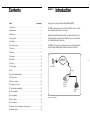
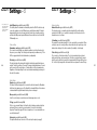
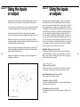
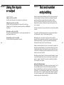
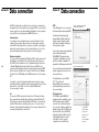
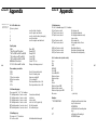
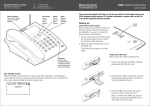
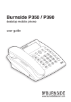
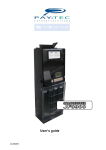
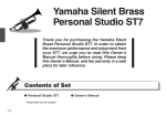
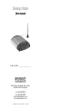
Desktop Mobile
User manual
The IMEI of my DTM is: ____________________________
Burnside Telecom Ltd, Burnside House, Isington,
ALTON GU34 4PP United Kingdom
Tel: +44 (0)8700 762766
Fax: +44 (0)1420 520029
Email: [email protected]
Web: www.burnsidetelecom.com
Part number 362002 / rev5. Firmware v2.0 or greater
Contents
Section
Section 1
page number
1. Introduction . . . . . . . . . . . . . . . . . . . . . . . . . . . . . . . . . . . . . . . . . . . . . . . . . . . 3
2. Getting started . . . . . . . . . . . . . . . . . . . . . . . . . . . . . . . . . . . . . . . . . . . . . . . . . 4
3. Making a call . . . . . . . . . . . . . . . . . . . . . . . . . . . . . . . . . . . . . . . . . . . . . . . . . . 6
4. Receiving a call . . . . . . . . . . . . . . . . . . . . . . . . . . . . . . . . . . . . . . . . . . . . . . . . 7
5. The display. . . . . . . . . . . . . . . . . . . . . . . . . . . . . . . . . . . . . . . . . . . . . . . . . . . . 7
6. Accessing the menu . . . . . . . . . . . . . . . . . . . . . . . . . . . . . . . . . . . . . . . . . . . . . 8
7. Phone book . . . . . . . . . . . . . . . . . . . . . . . . . . . . . . . . . . . . . . . . . . . . . . . . . . . 9
Introduction
Thank you for choosing the Burnside Desktop Mobile (DTM).
The DTM is a shared resource for home office, field office, boat or locations
where a landline is impractical or uneconomic.
What separates the Burnside product from other similar devices is its selfexplanatory display screen and its built-in functions more commonly found
on a hand held personal mobile phone.
The DTM can of course be used in the same way as a normal telephone line.
Follow the simple ‘Getting Started’ instructions to make your first call.
8. Messages. . . . . . . . . . . . . . . . . . . . . . . . . . . . . . . . . . . . . . . . . . . . . . . . . . . . . 11
9. Call register . . . . . . . . . . . . . . . . . . . . . . . . . . . . . . . . . . . . . . . . . . . . . . . . . . . 13
GSM/GPRS
Mobile Network
10. Call divert. . . . . . . . . . . . . . . . . . . . . . . . . . . . . . . . . . . . . . . . . . . . . . . . . . . . 14
3
11. Settings . . . . . . . . . . . . . . . . . . . . . . . . . . . . . . . . . . . . . . . . . . . . . . . . . . . . . 15
12. Terminal mode . . . . . . . . . . . . . . . . . . . . . . . . . . . . . . . . . . . . . . . . . . . . . . . . 18
Mobile Phone
Antenna
13. Help . . . . . . . . . . . . . . . . . . . . . . . . . . . . . . . . . . . . . . . . . . . . . . . . . . . . . . . . 18
14. Special call handling facilities . . . . . . . . . . . . . . . . . . . . . . . . . . . . . . . . . . . . . 19
15. Star Hash codes . . . . . . . . . . . . . . . . . . . . . . . . . . . . . . . . . . . . . . . . . . . . . . . 21
16. Remote commands . . . . . . . . . . . . . . . . . . . . . . . . . . . . . . . . . . . . . . . . . . . . 22
Burnside
Desktop
Mobile
17. Using inputs or output . . . . . . . . . . . . . . . . . . . . . . . . . . . . . . . . . . . . . . . . . . 24
18. Text and number entry/editing. . . . . . . . . . . . . . . . . . . . . . . . . . . . . . . . . . . . . 27
Telephone/
PBX
19. SMS compatibility . . . . . . . . . . . . . . . . . . . . . . . . . . . . . . . . . . . . . . . . . . . . . 28
20. Security features. . . . . . . . . . . . . . . . . . . . . . . . . . . . . . . . . . . . . . . . . . . . . . . 29
Figure 1: Basic configuration
21. Data connection . . . . . . . . . . . . . . . . . . . . . . . . . . . . . . . . . . . . . . . . . . . . . . . 30
22. Service settings . . . . . . . . . . . . . . . . . . . . . . . . . . . . . . . . . . . . . . . . . . . . . . . 32
23. Appendix - List of star and hash codes supported . . . . . . . . . . . . . . . . . . . . . . 34
24. Safety information . . . . . . . . . . . . . . . . . . . . . . . . . . . . . . . . . . . . . . . . . . . . . 36
Section 2
Getting started
Section 2
To use the terminal you will need:
f a suitable SIM,
f a normal touch-tone telephone with alpha characters on the keypad
(preferably one that displays caller ID)
f a power source.
Making the connections
Ensure that the following steps are followed accurately as there may be a risk of
damage to the unit if sockets are wrongly connected.
Antenna
connection (2)
RS232 computer
connection (1)
DC input (3)
Getting started
1 FME Female connector
2 RJ11 type
Step 2 – Connecting the antenna
To socket 2, attach the supplied antenna or another GSM antenna with a suitable
connector1. The connector nut only needs to be finger tight, do not apply
excessive force.
Locate the antenna in a convenient position at least one meter from your
telephone to avoid interference. If the signal strength is not strong, you may
need to adjust the position of the antenna. Use the signal strength indication
(see page 32) to find the optimum location.
SIM ejector (4)
4
Figure 2: View of rear
SIM tray(5)
Telephone
connection (6)
Input(s)/Output (7)
1 meter minimum
Step 1 - Installing a SIM
1. Remove the SIM tray by pressing the ejector button using a suitable pointed
object such as a ballpoint pen. After the tray has ejected about 2mm, pull it out
completely with your finger and thumb. Note how
the tray slides into guides. See Figures 2 and 4.
2. Place your SIM with gold contacts upper most into
the tray by placing corner A against side A of the
SIM tray See Figure 3.
A A
Figure 3
3. Now lower the SIM and press it snugly into the tray. The SIM must sit flush
with the tray.
4. Insert the SIM tray with the SIM back into the slot
and press it all the way until the tray becomes
flush with the panel. Note: make sure that the
tray slides correctly in the guides.
Figure 5: Keep the antenna away from the telephone
Step 3 – Connecting a telephone
Connect a touch-tone phone to socket 6. If your phone has a different connector
from the standard2, use an adaptor (supplied in some kits).
Step 4 – Connecting the power
To socket 3, connect the DC power connector from the supplied mains adaptor
or a suitable alternative.
Step 5 – Apply power
Apply power and the terminal display
will momentarily show the product
name and the software version. It will
then show the date and time, signal
strength and network operator.
Figure 4
You are now ready to make your first call.
5
Section 3
Making a call
Sections
4/5
Making a call
Lift the handset and listen for a dial tone. Dial the number you want and the call
will be connected. To end the call, hang up. The last call duration can be viewed
in the call register. (See page 13)
Receiving a call
When the phone rings, lift the handset and take the call in the normal way. If the
caller’s number is sent, it will be shown on the display of the terminal before the
handset is lifted and also shown on the phone (if the phone supports Caller ID
and the facility is enabled in menu 524, see page 16). If the “Allow reject” option
is enabled (see page 16), the call will only be accepted after lifting the handset
and pressing 0. If the handset is just lifted and replaced, the call will be rejected.
To dial an international number, you must use the +44 convention (44 is the
code for the UK) where the plus character precedes the country code followed
by the number you want. The + is entered by pressing and holding the 0 key.
To make a speed dial call, you must first assign a phone number to one of the
speed dialling keys (see page 9). Key the speed dial number you want and the
phonebook entry against that number will be displayed. Press 0 to confirm and
the call will be made. Note that some network operators pre-program useful
numbers into speed dial locations 1 to 9. These can be changed to your
own requirements
6
Receiving a call /
The display
The display
The current activity of the terminal is shown on the display. The display is
permanently backlit and the light will automatically dim to save power.
In normal “idle” condition, the top line of the display shows the date and time
together with a small bar graph for signal strength and indication when
connection to a compatible GPS receiver is made (see page 31).
The GSM operator to which the terminal is connected is shown on the bottom
line of the display.
Status information such as missed calls; messages received and so on are
displayed as required.
7
Section 6
Section 7
The menu functions are accessed by dialling 0# then stepping through the menu
list using the * and # keys. When the item you want is shown in the display, it is
selected by pressing the 0 key (remember that the 0 key means OK in those
modes). You can also access a menu item by dialling its shortcut number.
Example: 0#11 will select the phone book search.
The phone book uses the SIM memory to store names and numbers.
The capacity of the SIM may vary. The terminal will display details of capacity
when appropriate.
Menu Functions
1. Phone book
1 1 Search
1 2 Add entry
1 3 Edit
1 4 Status
1 5 Erase
1 5 1 Single entry
1 5 2 All entries
8
Phonebook – 1
Accessing the menu
2. Messages
2 1 Write message
2 2 Inbox
2 3 Outbox
2 4 Message Settings
3. Call register
3 1 Missed calls
3 2 Received calls
3 3 Dialled numbers
3 4 Erase dialled list
3 5 Show durations
3 6 Show GPRS log
3 7 Clear GPRS log
4. Call divert
4 1 Divert all
4 1 1 Activate
4 1 2 Cancel
4 1 3 Status
4 2 Divert when busy
4 2 1 Activate
4 2 2 Cancel
4 2 3 Status
4 3 Divert no answer
4 3 1 Activate
4 3 2 Cancel
4 3 3 Status
4 4 Divert when off
4 4 1 Activate
4 4 2 Cancel
4 4 3 Status
4 5 Cancel diverts
5. Settings
5 1 Terminal settings
5 1 1 Display contrast
5 1 2 Security settings
5 1 2 1 SIM PIN state
5 1 2 2 Change SIM PIN
5 1 2 3 Terminal PIN state
5 1 2 4 Change term PIN
5 1 2 5 Auto SIM unlock
5 1 3 Service Settings
5 1 3 1 Signal test
5 1 3 2 Show voltage
5 1 3 3 Show temperature
5 1 4 Restore factory settings
5 2 Phone settings
5 2 1 Own number sending
5 2 1 1 Activate
5 2 1 2 Cancel
5 2 1 3 Status
5 2 2 Dial delay
5 2 3 Alert settings
5 2 3 1 Ring tone
5 2 3 2 Ring for new
message
5 2 4 CLI type
5 2 5 Allow reject
5 3 Network settings
5 3 1 Network selection
5 3 1 1 Auto
5 3 1 2 Manual
5 3 2 Call waiting
5 3 2 1 Activate
5 3 2 2 Cancel
5 3 2 3 Status
5 4 Data settings
5 4 1 Baud rate
5 5 Input/Output settings
5 5 1 Channel 1
5 5 1 1 Polarity
5 5 1 2 Input or Output
selection
5 5 1 3 Text to send
5 5 1 4 Test connection
5 5 2 Channel 2
5 5 2 1 Polarity
5 5 2 2 Voltage level
5 5 2 3 Text to send
5 5 2 4 Test connection
5 6 Set clock
6. Terminal mode
6 1 Lock outgoing calls
6 2 Monitor inputs
6 3 Disconnect from network
7.Help
We recommend the
use of a telephone
with programmable
keys to store
frequently used
access codes.
The names you have stored in your phonebook are listed alphabetically. The
exception to this are the first nine entries which can be dialled using the keys 1
to 9 (speed dialling). You are provided with the option of storing an entry at one
of these locations. When setting up the phonebook for the first time, programme
the nine most frequently used numbers first. Entries cannot be moved once they
are entered, but can be edited, erased and replaced.
Search (press 0# followed by 11)
Use this function to locate the person or organisation you want to call.
Enter the first letter or just hash to display the first entry in the list. Scroll through
the list using the * and # keys. When you see the flashing block cursor on the
entry you want, press 0 for OK. You will then have the opportunity to confirm
calling the number by pressing 0 once more or press * to make a new search.
Add entry (press 0# followed by 12)
Use this function to add an entry to the phonebook.
If there is space, you will be prompted to enter either the speed dial location
number 1 to 9 or # if you do not wish to specify a speed dial location. If one of
the speed dial locations is already occupied, you will be given the chance to
replace that entry. Next, the number of characters allowed for the name text
appears. Using your telephone’s alpha keys, enter the name text (see section on
text entry page 27). When complete, enter #, after which the maximum number
of phone number digits allowed will be shown. Now enter the number followed
by # and the entry will be saved. If you hang up at any time before this, the entry
will be discarded and the phonebook will not be changed.
If the phonebook is full, you will be informed and you will need to make space
for the new number by deleting an existing entry.
9
Section 7
Phonebook – 1
Section 8
Edit (press 0# followed by 13)
Select the entry you want to modify by entering the first letter of the name or #
to scroll through the entries. Once selected, the entry cursor will show at the
start of the name text. Edit the text as required. Press # to display the number.
Edit the number as required. (To skip to the end of the entry press and hold #).
Press # again and the changes will be saved. If you hang up at any time before
this, the changes will be discarded.
The inbox and outbox messages are stored in the SIM memory and the number
of messages available varies depending on the capacity of the SIM. The most
recent edited message and the sensor messages (see page 25) are stored in the
terminal's internal memory and this information is retained even when the power
is removed.
Status (press 0# followed by 14)
This displays the number of phonebook entries used and the number available.
Erase single entry (press 0# followed by 151)
Use this function to erase an individual phonebook entry.
Select the entry you want to erase by entering the first letter of the name or #
to scroll through the entries. Once selected press 0 again to confirm erase.
10
This can be aborted at any time before the “Erased” message appears by
pressing * to go back or hanging up.
Messages – 2
Write messages (press 0# followed by 21)
Messages are composed with this function.
Start entering your text. (See the section on text entry page 27). The display
shows the number of characters remaining before the message memory is full
(total of 160) on the top right of the display.
Once the message is complete and the cursor is at the end of the message,
press # again and the prompt “Save to outbox?” will be displayed. Press 0 to
accept or press # again to enter the phone number or search the phonebook.
After selecting the destination number, press # again and the message will be
sent. To go back, press the * key.
Erase all entries (press 0# followed by 152)
Use this function to erase the entire contents of the phone book.
If the message memory contains any text from a previous message, you will be
prompted “Clear existing message?” To clear the memory, press 0, otherwise
press # to start editing the previous text.
This function is protected from accidental use by requiring the terminal PIN
to be entered first. Once correctly entered, confirm by pressing 0.
Inbox (press 0# followed by 22)
This is where incoming messages are stored.
The erasing process takes about 15 seconds for 200 entries.
To view a message, select the inbox from the menu and press 0. The display will
show a list of messages in the inbox. The list is shown in chronological order.
An icon indicates if a message has been read or not and the phone number that
sent the message. Move up and down the list and press 0 when you reach the
entry you want. The date and time that the message was sent will then be
displayed. Press # again and the message text will be shown.
(Tip: key 0# quickly to skip to the text)
Scroll through the message using the * and # keys. By pressing # again you will
be prompted to delete the message. If you want to delete, press 0 otherwise
press * to return to viewing the message.
11
Section 8
Messages – 2
Section 9
When the inbox is full and new message(s) are waiting to be received, an alert is
shown on the display to remind you to delete read messages to make room for
new ones (deleting messages from the outbox will also free up space).
The unit registers missed, received and dialled numbers.
The call register also provides another quick way of making a call.
Outbox (press 0# followed by 23)
This is a storage location for saving messages that you create and want to keep.
You can use this facility to store template messages as well.
When viewing the list of outbox entries, the first 12 characters of the message
are shown. Select the item you want by pressing 0. The text can now be edited
in the normal way before sending. Press and hold the # key to take you to the
end of the message. Press the # key twice and enter the destination number or
search your phonebook. To delete messages from outbox, press # at the end of
the message then 0 to erase.
12
Note: Editing an outbox message prior to sending, will not change the actual
content of the outbox, just the message that is sent.
Call register – 3
Missed calls (press 0# followed by 31)
This shows a list of those people who called but were not answered. When
scrolling through this list, you will be given the opportunity to call the number.
Received calls (press 0# followed by 32)
These are calls that were answered. The facility to call the number also applies.
Dialled numbers (press 0# followed by 33)
These are calls that were made from the handset (not via phonebook). The
facility to call the number also applies.
Erase dialled list (press 0# followed by 34)
This erases the dialled number list for privacy.
13
Message settings (press 0# followed by 24)
Use this to change the message centre number.
Show durations (press 0# followed by 35)
This shows the last call duration and the total call duration of the terminal since
manufacture.
When this item is selected the existing number is shown and it may be
edited/replaced with a new number which would be provided by your service
provider. This facility is not normally required.
Show GPRS log (press 0# followed by 36)
This shows the accumulated total of transmitted (sent) and received data. The
log is updated at the end of a GPRS session.
Cell broadcast/information service is not supported.
Clear GPRS log (press 0# followed by 37)
This clears both the transmit and received data log.
N.B. If a SIM is changed for a different one, the registers are automatically
erased. If the SIM is removed and replaced with the same SIM the registers
remain as they were.
Section 10
Call divert – 4
Section 11
This section supports the facility to divert voice calls to another number.
To control the DATA, SMS and FAX divert facilities, use the *# codes (see
Appendix). For diverting to voicemail, see the instructions provided by your
service provider.
These commands support the setting of various facilities and conditions for
both terminal and telephone related functions.
Each of the divert menus (41,42,43,44) are provided with three sub-menus for
Activate, Cancel and Status.
When activating a diversion, a phone number must be specified or a phonebook
entry used to provide the number. Once a number is entered, it is “registered” in
the network.
When cancelling a diversion, the previously registered number is retained.
14
When reactivating a divert, you are given the opportunity to delete the currently
registered number or enter a new number. To just delete the number, hang after
deleting. Otherwise continue be entering a new number or editing the existing one.
To view the current state of forwarding for a given type, use the status function.
If forwarding is active, the destination number that calls are forwarded to will be
displayed. When viewing the status, it is possible to step to the cancel menu and
conveniently cancel the divert.
Divert all (press 0# followed by 41)
All voice calls are diverted.
Divert when busy (press 0# followed by 42)
Diversion of voice calls received when the phone is busy.
Divert no answer (press 0# followed by 43)
Voice calls received but not answered will be diverted after 20 seconds.
Divert when off (press 0# followed by 44)
Diversion of voice calls made to the terminal when the unit is either powered off
or off-air (see menu item 63 on page 18).
Cancel diverts (press 0# followed by 45)
All call forwarding conditions will be cleared.
Settings – 5
Terminal settings
Display contrast (press 0# followed by 511)
Place the unit in the preferred operating position and use the * and # keys to
change the contrast of the LCD display. When the contrast is optimal, press 0 to
save the setting.
Security settings
SIM PIN state (press 0# followed by 5121)
This function is used to specify if the SIM PIN is required. If the facility is
enabled, every time the unit is powered up or logged on the PIN will be required.
If the PIN is incorrectly entered, the number of tries remaining (3 in total) is
displayed. If the number of tries expires, the PUK (PIN Unblocking Code) will be
required and this must be entered using the **05* code (see pages 29 and 34).
Change SIM PIN (press 0# followed by 5122)
This function allows a new PIN to be set. The old PIN is first requested followed
by the new PIN, which also needs to be repeated. If the OLD PIN is incorrectly
entered, the security measures apply where the number of tries to change the
PIN are displayed and after 3 failed attempts the blocked state is entered and the
PUK is required.
Terminal PIN state (press 0# followed by 5123)
This specifies if the terminal PIN is required. The terminal PIN is used to prevent
unauthorised use of the terminal and also for remote monitoring and control
functions. If the terminal PIN is enabled, the unit will request the PIN when
power is applied, or if the remote monitoring and control mode or Terminal lock
mode is being used. See the section on terminal mode (page 18).
Change terminal PIN (press 0# followed by 5124)
The old PIN must be entered correctly then the new PIN needs to be entered
twice before it is accepted. The PIN is fixed to 4 digits in length and defaults
to 1234.
15
Section 11
1 The possible options are
None (default), ETSI/UK
(European), Bellcore
(USA) and ETSI DTMF
(old European).
Settings – 5
Section 11
Auto SIM unlock (press 0# followed by 5125)
This facility allows the terminal to automatically unlock the SIM. This function only
comes into operation once the SIM pin has successfully been entered. If that had
happened before the auto option was selected, the auto unlock would operate the
next time the SIM pin was required. Otherwise the user will have to enter the SIM
PIN manually once.
Network settings
Network Selection (press 0# followed by 5311)
The network operator is normally selected automatically from information
provided in the SIM. It is not possible to manually select the network in the
standard version of software.
Phone settings
Own number sending (press 0# followed by 521)
This is used to select whether your telephone number is sent from the network to
the person you are calling. This setting can be temporarily overridden using *31# or
#31# as appropriate before the dailed number (see Appendix).
16
Dial delay (press 0# followed by 522)
This sets the delay after entering the last digit to calling the number that has been
entered. The factory setting is 3 seconds. The range is adjustable between 1 second
and 5 seconds in 0.5 second steps or 1 minute which is in effect a manual mode.
Regardless of the delay setting, the call can be started immediately by entering # at
the end of the number.
Alert settings
Ringtone (press 0# followed by 5231)
This allows 4 different ringtones to be selected to allow the terminal to differentiate
itself from other ringing sources. The default is the standard UK tone. Each cadence
is demonstrated through the handset as the options are changed.
Message alert (press 0# followed by 5232)
Select for a short ring to sound when a new text message arrives or not.
CLI type (press 0# followed by 524)
CLI is a very convenient feature. It allows the caller’s telephone number, date, time
and name (if there is a match in your phonebook) to be sent to the attached
telephone. Phones that support CLI are not expensive so it is recommended to use
one with the terminal1.
Allow reject (press 0# followed by 525)
This option allows the user to turn on or off the call rejection option (see page 7)
Settings – 5
Call waiting (press 0# followed by 5321)
This enables the call waiting facility if it is also provided by your network. When
activated, a new call coming in will provide an indication by a quiet beep on the
handset and a display of the caller's number (if available) on the display.
Clock setting (press 0# followed by 56)
This is used to set the date and time. The clock is maintained by an internal
battery and will keep quite accurate time. The battery is automatically charged
while the unit is switched on and will last approximately 30 days with the power
off. It will be fully charged after the terminal has been powered for about 2 days.
17
Sections
12 /13
1 The possible options are
None (default), ETSI/UK
(European), Bellcore
(USA) and ETSI DTMF
(old European).
Terminal mode – 6 /
Help – 7
Section 14
Lock outgoing calls (press 0# followed by 61)
When you enter this menu you will be requested to enter the terminal PIN. This
is fixed to 4 digits and the default is 1234. After the lock is enabled, only
incoming or emergency outgoing calls may be made.
Incoming call during menu access
If a call comes in during interaction with user functions for example editing the
phone book, a ringing tone will be heard through the handset. When the handset
is replaced, the phone will ring and the call may be answered in the normal way.
Monitor input(s) (press 0# followed by 62)
When you enter this menu you will be requested to enter the terminal PIN.
This is fixed to 4 digits and the factory setting is 1234. After the lock is
selected, only incoming or emergency calls may be made and the input(s) will be
monitored. If the input conditions are met, an SMS is sent to the number
programmed in menus 5513 and/or 5523 (see pages 24,25,26).
18
In this mode the power supply level is also monitored and if it falls bellow 10
volts for a 12 volt supply or 20 volts for a 24 volt supply, an alert is sent to the
number allocated to channel 1 or to channel 2 if channel 1 is used as an output.
Disconnect from network (press 0# followed by 63)
Use this to disconnect from the network. This is equivalent to switching off a
mobile phone.
In this state the “Divert when off” condition applies (see page 14). Picking up the
handset will initiate a request to “log on?”. Pressing 0 will cause the terminal to
re-connect to the network and request a SIM pin or terminal pin if so enabled
Help (press 0# followed by 7)
This displays the most important key sequences to operate the unit.
Special call
handling facilities
Call waiting
As long as call waiting is enabled and supported by your network, a call waiting
situation will occur if a new call comes in during an existing call. When this
happens, the number or name (if identified in the phone book) is displayed with
“waiting” shown and a tone can be heard in the handset.
The user has the following options:
1. Ignore the tone and message and wait until the caller either hangs up or is
diverted to voicemail if enabled.
2. Press recall button on the phone (or quickly tap the hook switch).
The display will show “Accept & hold?” with the waiting number on the
second line. Pressing 0 will accept the call and hold the previous call.
3. Press # and the display will show “Reject?” pressing 0 now will reject the
waiting call and return to the previous call.
Call(s) held and multiparty (conference) calls
If one or more calls are held after accepting a call-waiting or dialling another
number, the user has the following options:
1. Press recall on the phone (or quickly tap the hook switch). The display will
show “Reject?”. Pressing 0 will reject the current active call and return to the
held call(s).
2. Press # and the display will show “Add?”. Pressing 0 now will add the held
call(s) to the current call and provide a multiparty call.
3. Press # again and the display will show “Swap?”. Pressing 0 will place the
existing active call on hold and connect to the held call(s).
19
Section 14
20
Special call
handling facilities
Section 15
In-call dial
If during a call, you want to make another call without ending the current call,
follow this procedure:
1. Press the recall on the phone and the display will show “Dial number# or 0#
for Ph. Book”.
2. Dial the number, speed dial or use the phone book and the call will be
connected in the normal way. Once connected, the display will show 1 active
call and the number of held calls.
3. If it is not possible to connect the call, for example the line is busy or no
reply, you will be automatically returned to the held calls.
4. If the new call is connected, use the Call Held options as shown on the
previous page either reject, create a multi-party call or switch between calls.
Star hash codes may be used to control less commonly used facilities and
security features. To use, lift the handset and enter the code. A response will be
shown on the display. It is not necessary to hang up before entering a new code.
A list of supported codes is shown in the Appendix.
Aborting fax or data calls
If a data call or fax call is in progress between the DTM and a connected
computer, it is not possible to make a voice call at the same time. However it is
possible to abort the data/fax call using the following procedure:
1. Lift the handset and attempt to make an outgoing call, for example by
dialling 01. The DTM will immediately indicate it is not possible to dial a
voice call by displaying “Busy, hang up” and outputting a busy tone.
2. Press the recall on the handset which will cause the display “Abort
data/fax?” Pressing 0 at this point will end the data or fax call.
Notes:
a) During in-call option selection, to return to a previous option press the * key.
b) Hanging up the phone will terminate all calls (held, calling, active or waiting).
c) The availability of these options are dependant on the SIM card and service
provider. If a service is not provided, a message such as “operation not
supported” or “ss not executed” where ss means Supplementary Service.
d) If you try to add a party to a multiparty call and the call is answered by the
mailbox, you should disconnect the call otherwise the conference may be
recorded to the mailbox until it becomes full.
Star hash codes
21
Section 16
Remote commands
Section 16
A powerful and unusual feature is provided where certain facilities may be
controlled remotely by sending an SMS to the terminal.
Only the first two characters of the commands are required. The command is not
case sensitive. Example 1234sT
Status example:
Monitor: off
Lock: off hthe terminal lock condition
Input1: clear hif this is configured as an output, “input1” is replaced with
“Output:”
Input2: 2.5v-c hthe logical condition is also shown, c for clear, s for set
Missed calls: 13
New SMS: 14
SMS space: 11
Signal: -38dBm
Supply: 12.1v
Supply: break hthis is shown if power was lost after monitoring was started
Temp: 24C
Command list
SET This will set the channel 1 output if it is enabled.
CLEAR This will clear the channel 1 output if is enabled.
ON This will activate input monitoring and lock the terminal.
OFF This will deactivate input monitoring but the terminal will remain locked.
UNLOCK This will deactivate input monitoring if active and unlock the terminal.
LOCK This will lock the terminal.
STATUS This will return the status to the caller:
GPS This will return GPS data if a compatible GPS receiver is connected
and operating.
GPS example:
Latitude:
50deg 57.741’N
Longitude:
002deg 19.568’W
Speed: 000.0 kt
Track: 008.0 deg
Var: 004.8deg W
Time: 17:59:10
Date: 30/04/04
In all cases the terminal will respond by sending an SMS to the number that sent
the command. The response is either the new status of the terminal or an error
message if the command is not recognised. It is not possible to guarantee that
an SMS message will be delivered immediately. There are rare occasions when
the message will not be sent at all. That is why the terminal always sends a reply
to acknowledge the command and make it clear what state the terminal is in.
Generally the terminal will respond very quickly as most messages are received
without delay.
The DTM replies with the most recent fix data it received from the GPS receiver
even if the GPS receiver is subsequently switched off. However when power is
removed from the DTM, the last GPS fix is lost and the reply “GPS not
connected or functioning.” is provided. If the GPS is functioning but cannot get a
fix, the reply “No GPS fix available.” is provided.
A GPS receiver connected to the serial port enables the user to determine the
location of the system (see following page).
To operate: send an SMS message to the terminal. The first 4 characters must
be the terminal PIN. This is then followed by the command of your choice.
Example: 1234 status will cause the terminal to give information about its status
to the number that sent the command.
22
Remote commands
23
Section 17
Using the inputs
or output
Section 17
By simply connecting a switch of almost any kind including a magnetic door switch,
float switch and so on, it is possible to create a very effective monitoring system.
The software allows the polarity of the input(s) or output to be programmed.
When using the test menus 5514 and 5524 the physical levels are referred to,
whereas the remote status command returns the logical condition as defined by
the programmed polarity. For example you may configure input 1 to be active
low and input 2 to be active high above a 2.5v threshold. In this case Input 1 will
show TRUE when low and Input 2 will show TRUE when high. Note that Input 2
can be considered as logic input if the threshold is set at the default of 2.5v.
Tip: If you wanted to send an SMS to two different locations for a single event,
you could connect both inputs together but have different numbers set for each.
Tip: If you only want to monitor the supply voltage, enable Input 1 “Active low”
but do not connect anything to it. The input will remain high so configure Input1
to be “Normally open”. The Input event will never become true, but the battery
monitor will send an alert to the number allocated to Input 1.
There are two connections, 1 and 2. Connection 1 can be configured as either an input
or output by the settings menu 5512 (see page 25) Connection 2 is an input only.
Connections are made via a 3.5mm “stereo” style jack plug, which is supplied.
Connection 1 (jack tip) when used as an input responds to two conditions, high or low.
When used as an output, it is a so called “open collector” type which is suitable for
providing a logic signal or driving a low power relay coil with an external power source
and suitable external back emf protection diode.
Connection 2 (jack ring) is an analogue input, which responds to a voltage level. The
software in the terminal provides 9 levels of monitoring at 0.5 volts steps providing
levels of between 0.5 volts and 4.5 volts.
24
Both inputs are heavily filtered to protect internal components from damage due to
voltage spikes or interference.
Using the inputs
or outputs
Input/Output settings (press 0# followed by 55)
The input and output capability usefully exploits the ability of the terminal to
send and receive SMS. Two channels are provided. Channel 1 is a logic level
input or output. Channel 2 is analogue input only and can be set to trigger at a
certain voltage threshold (see page 26).
Channel 1 (input or output)
Polarity (press 0# followed by 5511)
Use this to select if this is to be normally closed or normally open. This level
selection applies to either the input or output mode whichever is selected.
Input or Output selection (press 0# followed by 5512)
Use to set channel 1 to an input or an output.
Text to send (press 0# followed by 5513)
This uses the normal SMS editing method to create a message and number to
call when the input condition it met.
Test connection (press 0# followed by 5514)
This displays the input condition or allows the output to be toggled to test the
connection.
Figure 6: Input/output interface circuit
25
Section 17
Using the inputs
or output
Section 18
Channel 2 Input only.
Polarity (press 0# followed by 5521)
Use this to select if this input is to be normally closed or normally open.
Characters are entered using the telephone keys 0 to 9. Each key has a number of
characters assigned to it as shown on the keys of most telephones. Repeatedly
pressing a key will take you through the characters available on that key.
The choice of characters allocated to each key is shown on the top line of the
display. After a short delay or a different key is pressed, the character above the
cursor is accepted.
Voltage level (press 0# followed by 5522)
Use this to select the threshold between 0.5 volts and 4.5 volts in 0.5 steps.
Setting the level to 2.5V will effectively provide the same facility as a CMOS digital
level detector.
Text to send (press 0# followed by 5523)
This uses the normal SMS editing method to create a message and number to call
when the input condition it met.
Test connection (press 0# followed by 5524)
This shows the input voltage present (0.5v resolution).
26
Text and number
entry/editing
The 0 key is mainly used for the space character but also includes other formatting
characters.
It is possible to switch between upper and lower case by pressing and holding a
key. This behaves like “caps lock” as it will remain in that state.
Momentarily press the * and # keys to move the cursor left or right in the
message. To delete a character press and hold the * key and one character will be
deleted. Continue holding the * key and characters will be deleted repeatedly.
Press and hold the # key to skip to the end of the message.
Characters are always inserted into the text so if a word needs to be replaced, first
delete it by pressing and holding the * key. The character pointed to by the cursor
is deleted and the characters from the right of the cursor are shifted. If the cursor
is at the end of the message the characters are deleted under the cursor as before
but the cursor also moves to the left.
When editing a phonebook name, the first letter is automatically made to be upper
case and the subsequent letters are lower case. After a space is entered the same
applies. For example “John Smith”. It is possible to override this by holding the
key to change the case as required.
Entering and editing phone numbers
When entering phone numbers, it is possible to move the cursor using the * and #
keys, delete digits and skip to the end as with text editing, however digits are
always overwritten with new ones at the cursor position and not inserted as with
text characters. To store international phone numbers use the + character followed
by the country code. The + is entered by holding down the 0 key. If the terminal is
on the move for example on a boat, we would recommend using the full number
including country code for all phonebook entries.
27
Section 19
SMS compatibility
Section 20
The terminal is designed to support basic text messaging. If the terminal is sent
picture messages, business cards or other special messages these may be
displayed as meaningless message text. If this occurs, delete the message.
When entering PINs, there are no editing functions. Take care to correctly enter the
PIN. The digits entered are displayed with the * character so PIN 1234 would be
displayed as ****. The SIM PIN mechanism is designed to provide a high level of
protection. Three attempts are provided for the normal PIN entry after which the
unblocking code will be required (PUK). This is protected by several levels of time
prevention to avoid repeated guessed attempts. A total of 10 attempts are allowed
before the SIM is unusable.
The terminal is capable of displaying the full range of GSM characters*. When a
character is received that is not supported, it is replaced with ¿or a block character.
Security features
Characters assigned to each key*
*The character set is subject to change.
Key
Characters
Key
Characters
1
.1?!,@_&:"'¿
no case change
6
MNO6ÑÖØòΩ
mno6ñöøòΩ
ABC2ÄÅàÆßç
abc2äåàæßç
7
3
DEF3Éèφ
def3éèφ
8
TUV8ÜÙ
tuv8üù
4
GHI4Γ ì
ghi4Γ ì
9
WXYZ9≡ ψ
wxyz9≡ ψ
5
JKL5Λ
jkl5Λ
0
0()%£$€¥#+(the first char is a space)
no case change
2
28
PQRS7Π β Σ
pqrs7Π β Σ
Time to wait before next PUK input is allowed:
1st failed attempt
No time to wait
2nd failed attempt
4 seconds
From 3rd failed attempt
256 seconds each time
The SIM pin can be between 4 and 8 digits. The PUK is always 8 digits and can be
obtained from your service provider.
The terminal PIN is fixed to 4 digits and the security measures are simpler. After 3
failed attempts, a delay of 1 minute is applied before accepting another attempt but
importantly the code stored for auto SIM unlock is erased. If the unit is powered off
and on again this delay is cleared.
The most important and potentially financially hazardous situation is to leave the
SIM unlocked. If the terminal PIN is lost, contact [email protected] for
a release code to restore the default.
Emergency calls only.
If the SIM is locked or there is not even a SIM in the terminal, it is still possible to
make emergency calls by dialling the 112 emergency number.
Auto unlock precaution:
The SIM auto unlock facility works by remembering the last successful PIN that
was used. If the auto-unlock facility is then enabled, it will unlock the SIM. However
if the SIM is changed for another SIM, the auto unlock facility is cleared.
IMEI code (International Mobile station Equipment Identity)
This is a unique 15 digit number that we recommend you write down in the front of
this manual in the place provided. To view this number dial *#06# or look on the
label on the underside of the unit. This number can be used by network operators
to permanently block the use of the terminal in the event of theft. You may also be
asked for this code when requesting support.
29
Section 21
Data connection
Section 21
An RS232 serial interface is provided to allow connection to a computer using
the supplied cable. If your computer does not support RS232 or you do not have
a spare connection, use the optional Burnside USB adaptor. It is also possible to
connect a GPS receiver that supports the NMEA-0183 protocol.
GPRS
If your SIM supports it, you can connect to
the Internet using the higher speed GPRS.
Standard modem
It is possible to set up a standard modem to connect to the Internet or other
computer. When you make a data connection, it is still possible to send and
receive SMS from the handset, but voice calls are not possible. If you attempt to
make a data connection during a voice call, it may disrupt your voice call. You
should avoid making a data connection while a voice call is in progress.
30
Windows configuration
To set up a connection in Windows XP (Windows 98SE is similar), under control
panel Modems, select Add. Check the “don't detect my modem” option and
select NEXT. Under “manufacturer” select “standard modem types” then select
“standard 19200 bps Modem” under “Models” then select NEXT. A list of
connections will be displayed. Select the one that is appropriate such as COM1.
Now the modem is installed, select “Properties” and then select the “Maximum
Port Speed” to be 115200. Make sure the DTM baud rate is set to Auto in menu
541.
If you want to connect to the internet using this modem connection, create a
new dialup networking configuration in the normal way suitable for your ISP and
make sure the “connect using” is set to the “standard 19200 modem”
You are now ready to connect.
Fax
You can use the DTM to send and receive faxes from a PC using fax software.
We recommend the fax capability that is installed as standard in Windows XP
Professional (free option provided with Windows XP Home). You can send a fax
with most SIMs and services including “pay as you go”. To receive a fax, you
will have to obtain a dedicated fax number from your service provider and this is
normally only available with a contract SIM.
Data connection
Figure 6: Initialisation string for GPRS
(example shown: Orange UK)
This will provide data rates typically
between 40kbps to 60kbps but this will
depend on network congestion, signal
quality and other variables. Contact your
service provider for details.
It is necessary to add an extra modem initialisation command (see Figure 6):
AT+CGDCONT=1,IP,yourprovider where
“yourprovider” is specified by your service
provider. For example “orangeinternet” is
appropriate for the Orange network in the UK.
Figure 7: Dial string for GPRS
You can retain this special command in the
modem configuration even if you use the
same modem for fax.
The dialled number to access GPRS is
*99***1# (see Figure 7).
During a GPRS session, the number of
bytes transmitted (sent) and received is
shown on the display.
GPS navigation data
The DTM will recognise NMEA-0183
navigation data that is available from most
GPS receivers that support an RS232
connection. The connection will require a
cross over cable or adaptor (available from
Burnside Telecom). Once the DTM receives
data from the GPS receiver the DTM will
display the character G (GPS) next to the
signal strength indication to show it is
connected. See section on remote
commands for use of the GPS data.
Use this button to
make sure that the
port connection
speed is also set to
115200 here.
Also select hardware
flow control.
31
Section 22
Service settings
Section 22
Service settings
Service Settings
Data settings
Signal Test (press 0# followed by 5131)
This function shows the signal strength in two forms:
a) The level in -dBm (the logarithmic scale relative to 1mw into 600Ω).
The displayed range is -113dBm (a very weak signal) to -51dBm (a very
strong sgnal).
b) The dBm level expressed as a percentage of the range as defined above.
Baud Rate (press 0# followed by 541)
The speed of the serial interface can be configured using this option. The default
setting is auto-baud rate detection which is suitable for GPRS, Fax, Modem and
NMEA GPS data. For special cases a manual setting can be selected in the range
300 to 115200. Note that some PC software may use more than one baud rate,
so it would then be essential to use the auto baud setting.
The signal display is updated several times per second so this can be used to
adjust the antenna in real time to find the optimal position (a smaller -db figure
is better). If the signal is too weak, consider using a directional antenna which
will offer a significant improvement. Consult your supplier for details.
32
Show supply voltage (press 0# followed by 5132)
This shows the power supply voltage between 8 and 32 volts. This measurement
is quite accurate (± 100mV) and can be used to determine the health of the
power supply. If the voltage is outside this range, take steps to correct the
situation.
Show temperature (press 0# followed by 5133)
This shows the temperature of the transmitter circuit inside the unit. The unit will
work perfectly under normal environmental conditions but in extreme heat such
as prolonged direct strong sunlight and high ambient temperature it is possible
for the transmitter circuit to get excessively hot. No harm will come to the unit
as it protects itself by shutting down (terminating the call) but viewing the
temperature with this facility can provide an early indication that the environment
is too hot.
Note that when transmitting continuously, the temperature of the circuitry rises
to about 10˚C above idle condition. The idle temperature is typically about 4˚C
above ambient.
Restore Factory (press 0# followed by 514)
This returns the terminal to factory settings, apart from the terminal PIN
GSM/GPRS
Mobile Network
Mobile Phone
Antenna
33
Telephone/
PBX
Burnside
Desktop
Mobile WO
Alarm
PC or Mac
Figure 9: Example configuration
This diagram shows a PBX or a phone connected to the DTM, a PC using the
DTM for modem, high speed GPRS connection or for fax communication. Also a
device that utilises the DTM remote alert function.
Section 23
1 Available via ATD command
over serial interface or via
handset during data call
34
Appendix
Section 23
List of Star Hash codes
The basic syntax is:
*
**
*#
#
##
used to activate a function.
used to register and activate.
used to check the status (interrogate).
used to deactivate.
used to unregister and deactivate.
Security group
*#06#
**04oldPin*newPIN*newPin#
**042*oldPIN2*newPIN2*newPIN2#
**05*unblKey*newPIN*newPIN#
**052*unblKey*newPIN*newPIN#
#0003MasterPhoneCode#
*03*330*oldPw*newPW*newPw#
Query IMEI
Change PIN1
Change PIN2
Unlock PIN1
Unlock PIN2
Unlock “PS” lock
Change call barring password
Call barring group
The 1st 5 commands support *,#,*# variations.
33*pwd*<service code>#
All outgoing calls
331*pwd*<service code>#
All outgoing international.
332*pwd*<service code>#
All outgoing international except
home country.
35*pwd*<service code>#
All incoming calls
351*pwd*<service code>#
All incoming outside of home
country
#330*pwd*<service code>#
Deactivate all barring
#333*pwd*<service code>#
Deactivate all outgoing barring.
#353*pwd*<service code>#
Deactivate all incoming barring
Phone number presentation
*#30#
*#31#
*31#<phone number>
#31#<phone number>
*#76#
*#77#
Show CLI presentation state.
Show CLI sending state.
Suppress sending CLI
Force sending CLI
Check presentation state of call
Check presentation state of call1
Call Forwarding group
These support all *,#,*#,**,## variations.
21*<dialling number>*<service code>#
67*<dialling number>*<service code>#
61*<dialling number>*<service code>#
62*<dialling number>*<service code>#
002*<dialling number>*<service code>#
004*<dialling number>*<service code>#
Forward unconditionally
when busy
when no reply
when “no reach” (signal lost)
All calls forwarded.
All conditional types
Call waiting group
This supports *,#,*# variations.
43*<service code>#
List of service codes (<service code>)
Voice
Fax
SMS
SMS+FAX
Voice+FAX
Voice+SMS+FAX
Data circuit async.
Data circuit sync.
PAD
Packet
Data circuit async+PAD
Data circuit sync.+packet
Data circuit asyn.+sync.+PAD
All services
Examples:
**67*08700762766*#
#67*
*67*
Activate/deactivate/interrogate
Appendix
11
13
16
12
19
10
25
24
27
26
21
22
20
-- (omit code)
will register and forward calls when
busy for all services to
08700762766.
will deactivate call forwarding when
busy.
will activate call forwarding to
08700762766 again.
35
Section 24
Important safety
information
Operating environment
Make sure that no special regulation is in
force that imposes restrictions on the use of
mobiles. Restrictions to mobiles would also
apply to the DTM.
36
Vehicles
RF signals may affect improperly installed or
inadequately shielded electronic systems in
motor vehicles (e.g. electronic fuel injection
systems, electronic anti-skid (anti-lock) braking
systems, electronic speed control systems, air
bag systems).
Electronic devices
Most modern electronic equipment is shielded
from radio frequency (RF) signals. However,
Check with the manufacturer or its
certain electronic equipment may not be
representative regarding your vehicle. You
shielded against the RF signals from your DTM. should also consult the manufacturer of any
equipment that has been added to your vehicle.
Pacemakers
Pacemaker manufacturers recommend that a
Potentially explosive atmospheres
minimum separation of 20 cm (6 inches) be
Do not install the DTM or site the antenna in
maintained between a hand-held wireless
any area with a potentially explosive atmosphone and a pacemaker. The same restriction
phere and obey all signs and instructions.
should apply to the external antenna of the
Areas with a potentially explosive atmosphere
DTM. If you have any reason to suspect that
are often but not always clearly marked. They
interference is taking place, switch off the
include below deck on boats; chemical transfer
DTM immediately.
or storage facilities; vehicles using liquefied
petroleum gas (such as propane or butane);
Hearing aids
areas where the air contains chemicals or
The DTM radio signals may interfere with some
particles, such as grain, dust or metal powders.
hearing aids. In such event move the antenna
as far away as practical or consult your hearing
Emergency calls
aid supplier.
Important! The DTM, like any wireless phone,
operates using radio signals, wireless and
Other medical devices
Operation of any radio transmitting equipment, landline networks, as well as user-programmed
functions, which cannot guarantee connection
including the DTM, may interfere with the
in all conditions. Therefore, you should never
function of inadequately protected medical
rely solely upon any wireless phone for essential
devices. Consult a physician or the
communications (e.g. medical emergencies).
manufacturer of the medical device to
determine if they are adequately shielded from
external RF energy or if you have any questions. Remember, to make or receive any calls the
DTM must be switched on and in a service
area with adequate cellular signal strength.
Switch off your DTM in health care facilities
Emergency calls may not be possible on all
when any regulations posted in these areas
wireless phone networks or when certain
instruct you to do so. Hospitals or health care
facilities may be using equipment that could be network services and/or phone features are in
use. Check with local cellular service providers.
sensitive to external RF energy.