1
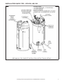
Service Handbook COMMERCIAL GAS HIGH EFFICIENCY WATER HEATERS MODELS COVERED: BTH 120 THRU 500 SERIES 100, 101 AND BTH 400/500 SERIES 104 500 Tennessee Waltz Parkway Ashland City, TN 37015 SERVICING SHOULD ONLY BE PERFORMED BY A QUALIFIED SERVICE TECHNICIAN PRINTED IN THE U.S.A. 1012 316586-002 TABLE OF CONTENTS INTRODUCTION . . . . . . . . . . . . . . . . . . . . . . . . . . . . . . . . . . . . . . . . . . . . . . . . . . . . . . . . . . . . . . . . . . . . . . 2 QUALIFICATIONS . . . . . . . . . . . . . . . . . . . . . . . . . . . . . . . . . . . . . . . . . . . . . . . . . . . . . . . . . . . . . . . . . . . . . 2 TOOLS REQUIRED . . . . . . . . . . . . . . . . . . . . . . . . . . . . . . . . . . . . . . . . . . . . . . . . . . . . . . . . . . . . . . . . . . . 3 GENERAL INFORMATION . . . . . . . . . . . . . . . . . . . . . . . . . . . . . . . . . . . . . . . . . . . . . . . . . . . . . . . . . . . . . . 4 GAS PRESSURE SPECIFICATIONS . . . . . . . . . . . . . . . . . . . . . . . . . . . . . . . . . . . . . . . . . . . . . . . . . . . . . . 4 INSTALLATION QUICK TIPS – BTH 120 AND 150: GAS PRESSURE . . . . . . . . . . . . . . . . . . . . . . . . . . . . 6 INSTALLATION QUICK TIPS – BTH 199 AND 250 GAS PRESSURE . . . . . . . . . . . . . . . . . . . . . . . . . . . . . 7 INSTALLATION QUICK TIPS – BTH 300, 400, 500 GAS PRESSURE . . . . . . . . . . . . . . . . . . . . . . . . . . . . . 8 INSTALLATION QUICK TIPS – BTH 300, 400, 500 . . . . . . . . . . . . . . . . . . . . . . . . . . . . . . . . . . . . . . . . . . . 9 INSTALLATION – VENTING CATEGORY AND MATERIALS . . . . . . . . . . . . . . . . . . . . . . . . . . . . . . . . . . . 10 VENTING TABLES – BTH 120 - 250 . . . . . . . . . . . . . . . . . . . . . . . . . . . . . . . . . . . . . . . . . . . . . . . . . . . . . . . 11 VENTING TABLES – BTH 300, 400, 500 . . . . . . . . . . . . . . . . . . . . . . . . . . . . . . . . . . . . . . . . . . . . . . . . . . . 11 CONCENTRIC VENTING . . . . . . . . . . . . . . . . . . . . . . . . . . . . . . . . . . . . . . . . . . . . . . . . . . . . . . . . . . . . . . 12 VENT CONDENSATION . . . . . . . . . . . . . . . . . . . . . . . . . . . . . . . . . . . . . . . . . . . . . . . . . . . . . . . . . . . . . . . 13 VENTING – ALL MODELS – SINGLE PIPE DIRECT VENT – USING OUTSIDE AIR TERMINATION CLEARANCES SIDEWALL POWER VENT . . . . . . . . . . . . . . . . . . . . . . . . . . . . . . . . . . . . . . . . . . . . . . . . 14 VENTING – ALL MODELS – TWO PIPE DIRECT VENT – USING OUTSIDE AIR TERMINATION CLEARANCES SIDEWALL DIRECT VENT . . . . . . . . . . . . . . . . . . . . . . . . . . . . . . . . . . . . . . . . . . . . . . . . 15 VENT TERMINATION – DIRECT VENT – ALL MODELS . . . . . . . . . . . . . . . . . . . . . . . . . . . . . . . . . . . . . . 16 DIRECT VENTING – ALL MODELS . . . . . . . . . . . . . . . . . . . . . . . . . . . . . . . . . . . . . . . . . . . . . . . . . . . . . . 17 CONTROL OVERVIEW . . . . . . . . . . . . . . . . . . . . . . . . . . . . . . . . . . . . . . . . . . . . . . . . . . . . . . . . . . . . . . . . 18 ADJUSTING TANK TEMPERATURE – OPERATING SET POINT – DIFFERENTIAL . . . . . . . . . . . . . . . . 20 CHANGING THE DISPLAY UNITS . . . . . . . . . . . . . . . . . . . . . . . . . . . . . . . . . . . . . . . . . . . . . . . . . . . . . . . 22 FAULT AND WARNING CONDITIONS – ADVANCED DIAGNOSTIC INFORMATION . . . . . . . . . . . . . . . . 24 ACCESS TO THE CURRENT FAULT OR WARNING . . . . . . . . . . . . . . . . . . . . . . . . . . . . . . . . . . . . . . . . . 25 FAULT CODES . . . . . . . . . . . . . . . . . . . . . . . . . . . . . . . . . . . . . . . . . . . . . . . . . . . . . . . . . . . . . . . . . . . . . . 26 VIEWING THE FAULT HISTORY – VIEWING INFORMATION ABOUT THE HEATER . . . . . . . . . . . . . . . 27 CONTROL SEQUENCE (TYPICAL ALL MODELS) . . . . . . . . . . . . . . . . . . . . . . . . . . . . . . . . . . . . . . . . . . 28 CONTROL SEQUENCE FLOW CHART . . . . . . . . . . . . . . . . . . . . . . . . . . . . . . . . . . . . . . . . . . . . . . . . . . . 29 CONTROLS – CENTRAL CONTROL BOARD – CCB . . . . . . . . . . . . . . . . . . . . . . . . . . . . . . . . . . . . . . . . 30 CONTROLS – GAS CONTROL VALVE BTH 120 . . . . . . . . . . . . . . . . . . . . . . . . . . . . . . . . . . . . . . . . . . . . 32 CONTROLS – GAS CONTROL VALVE BTH 150 . . . . . . . . . . . . . . . . . . . . . . . . . . . . . . . . . . . . . . . . . . . . 32 CONTROLS – GAS CONTROL VALVE BTH 199 AND 250 . . . . . . . . . . . . . . . . . . . . . . . . . . . . . . . . . . . . 33 CONTROLS – GAS CONTROL VALVE, ORIFICE CHART - BTH 300/400 - 100/101 . . . . . . . . . . . . . . . . 34 CONTROLS – GAS CONTROL VALVE, ORIFICE CHART – BTH 400/500 . . . . . . . . . . . . . . . . . . . . . . . . 35 CONTROLS – PRESSURE SWITCHES – ALL MODELS . . . . . . . . . . . . . . . . . . . . . . . . . . . . . . . . . . . . . 36 CONTROLS – PRESSURE SWITCHES – BTH 120 THROUGH 250 . . . . . . . . . . . . . . . . . . . . . . . . . . . . 37 CONTROLS – PRESSURE SWITCHES – BTH 300, 400, 500 . . . . . . . . . . . . . . . . . . . . . . . . . . . . . . . . . . 38 CONTROLS – CONNECTIONS, IGNITER, FLAME SENSOR, SIGHT GLASS, POWERED ANODES . . . 39 HOT SURFACE IGNITER / FLAME SENSOR / CONTROL TIMING . . . . . . . . . . . . . . . . . . . . . . . . . . . . . 40 BLOWER SPEED CONTROL BTH 199 AND 250 . . . . . . . . . . . . . . . . . . . . . . . . . . . . . . . . . . . . . . . . . . . . 41 VARIABLE FREQUENCY DRIVE – BTH 400 AND 500 . . . . . . . . . . . . . . . . . . . . . . . . . . . . . . . . . . . . . . . 42 VARIABLE FREQUENCY DRIVE – BLOWER SPEED AND PRESSURE READINGS . . . . . . . . . . . . . . . 43 WIRING DIAGRAM – BTH 120 - 300 . . . . . . . . . . . . . . . . . . . . . . . . . . . . . . . . . . . . . . . . . . . . . . . . . . . . . 44 WIRING DIAGRAM – BTH 400, 500 . . . . . . . . . . . . . . . . . . . . . . . . . . . . . . . . . . . . . . . . . . . . . . . . . . . . . . 45 Servicing should only be performed by a Qualified Service Technician 1 INTRODUCTION The service handbook is designed to aid in servicing and troubleshooting A. O. Smith Cyclone Xi BTH commercial water heaters in the field. No duplication or reproduction of this book may be made without the express written authorization of the A. O. Smith Corporation. The following text and illustrations will provide you with a step by step procedure to verify proper installation, operation, and troubleshooting procedures. Additional quick reference data is included to assist you in servicing these products. The information contained in this handbook is designed to answer commonly faced situations encountered in the operation of this product line and is not meant to be all inclusive. If you are experiencing a problem not covered in this handbook, please contact A. O. Smith Technical Information at 1-800-527-1953, by email at [email protected], or your local A. O. Smith Corporation representative for further assistance. Our website at: http://www.hotwater.com is also a resource for installation and service information. This handbook is intended for use by licensed plumbing professionals and reference should be made to the instruction manual accompanying the product. This handbook contains supplemental information to the product’s instruction and operation manual. QUALIFICATIONS ANSI Z223.1 Sec 3.3.83 “Qualified Agency” “Any individual, firm, corporation or company that either in person or through a representative is engaged in and is responsible for (a) the installation, testing or replacement of gas piping or (b) the connection, installation, testing, repair or servicing of appliances and equipment; that is experienced in such work; that is familiar with all precautions required; and that has complied with all the requirements of the authority having jurisdiction.” Service of this water heater requires ability equivalent to that of a Qualified Service Technician in the field involved. Installation skills such as plumbing, air supply, venting, gas supply, electrical supply are required in addition to electrical testing skills. Some products may require combustion testing equipment and certification. If you do not possess these skills or do not have the proper tools you should not attempt to service this water heater. 2 Servicing should only be performed by a Qualified Service Technician TOOLS REQUIRED • ELECTRICAL MULTIMETER CAPABLE OF MEASURING CONTINUITY/ OHMS, AC & DC VOLTS, AMPERES, MICROAMPERES, MILLIVOLTS, and FREQUENCY (Hz) • • UEi Model DL289 or equivalent DIGITAL MANOMETER + 60" W. C. in .01" increments Note: A digital manometer is required for testing pressure switches and can replace a gas pressure gauge, draft gauge or slack tube manometer for checking gas pressure. • UEi model EM200 or equivalent • WATER PRESSURE GAUGE w/LAZY HAND AND HOSE BIBB CONNECTION • THERMOMETER • 1-1/16 INCH SOCKET WITH EXTENSION FOR POWERED ANODE REPLACEMENT • SET OF NUMBERED DRILL BITS DIGITAL MANOMETER DIGITAL MULTIMETER WATER PRESSURE TEST GAUGE W/LAZY HAND AND HOSE BIBB CONNECTION Servicing should only be performed by a Qualified Service Technician 3 GENERAL INFORMATION INSTALLATION REQUIREMENTS FOR THE COMMONWEALTH OF MASSACHUSETTS For all side wall terminated, horizontally vented power vent, direct vent, and power direct vent gas fueled water heaters installed in every dwelling, building or structure used in whole or in part for residential purposes, including those owned or operated by the Commonwealth and where the side wall exhaust vent termination is less than seven (7) feet above finished grade in the area of the venting, including but not limited to decks and porches, the following requirements shall be satisfied: INSTALLATION OF CARBON MONOXIDE DETECTORS At the time of installation of the side wall horizontal vented gas fueled equipment, the installing plumber or gas fitter shall observe that a hard wired carbon monoxide detector with an alarm and battery backup is installed on the floor level where the gas equipment is to be installed. In addition, the installing plumber or gas fitter shall observe that a battery operated or hard wired carbon monoxide detector with an alarm is installed on each additional level of the dwelling, building or structure served by the sidewall horizontal vented gas fueled equipment. It shall be the responsibility of the property owner to secure the services of qualified service technicians for the installation of hard wired carbon monoxide detectors. In the event that the side wall horizontally vented gas fueled equipment is installed in a crawl space or an attic, the hard wired carbon monoxide detector with alarm and battery back-up may be installed on the next adjacent floor level. In the event that the requirements of this subdivision can not be met at the time of completion of installation, the owner shall have a period of thirty (30) days to comply with the above requirements provided that during said thirty (30) day period, a battery operated carbon monoxide detector with an alarm shall be installed. APPROVED CARBON MONOXIDE DETECTORS Each carbon monoxide detector as required in accordance with the above provisions shall comply with NFPA 720 and be ANSI/UL 2034 listed and CSA certified. SIGNAGE A metal or plastic identification plate shall be permanently mounted to the exterior of the building at a minimum height of eight (8) feet above grade directly in line with the exhaust vent terminal for the horizontally vented gas fueled heating appliance or equipment. The sign shall read, in print size no less than one-half (1/2") inch in size, “GAS VENT DIRECTLY BELOW. KEEP CLEAR OF ALL OBSTRUCTIONS.” GAS PRESSURE SPECIFICATIONS Natural 120‑150 Propane 120‑150 Natural 199‑250 Propane 199‑250 Natural 300/400/500 Propane 300/400/500 Maximum Gas Supply Pressure 10.5" WC (2.62 kPa) 14.0" WC (3.49 kPa) 10.5" WC (2.62 kPa) 14.0" WC (3.49 kPa) 11.0" WC (2.74 kPa) 14.0" WC (3.49 kPa) Nominal Gas Supply Pressure 7.0" WC (1.74 kPa) 11.0" WC (2.74 kPa) 7.0" WC (1.74 kPa) 11.0" WC (2.74 kPa) 7.0" WC (1.74 kPa) 11.0" WC (2.74 kPa) Minimum Gas Supply Pressure (Low Gas Press. Switch Setting) 4.8" WC (1.20 kPa) 11.0" WC (2.74 kPa) 4.8" WC (1.20 kPa) 8.5" WC (2.12 kPa) 5.2" WC (1.30 kPa) 11.0" WC (2.74 kPa) Manifold Pressure 4.0" WC (1.0 kPa) 10.0" WC (2.49 kPa) 0" WC (0 kPa) 0" WC (0 kPa) 4.0" WC (1.0 kPa) 10.0" WC (2.49 kPa) MODELS 4 Servicing should only be performed by a Qualified Service Technician GAS SUPPLY SYSTEMS Low pressure building gas supply systems are defined as those systems that cannot under any circumstances exceed 14” W.C. (1/2 PSI Gauge). These systems do not require pressure regulation. Measurements should be taken to insure that gas pressures are stable and fall within the requirements stated on the water heater rating plate. Readings should be taken with all gas burning equipment off (static pressure) and with all gas burning equipment running at maximum rate (dynamic pressure). The gas supply pressure must be stable within 1.5” W.C. (0.05 PSI Gauge) from static to dynamic pressure to provide good performance. Pressure drops that exceed 1.5” W.C. (0.05 PSI Gauge) may cause rough starting, noisy combustion or nuisance outages. Increases or spikes in static pressure during off cycles may cause failure to ignite or in severe cases damage to appliance gas valves. If your low pressure system does NOT meet these requirements, the installer is responsible for the corrections. High pressure building supply systems use pressures that exceed 14” W.C. (1/2 PSI Gauge).These systems must use field supplied regulators to lower the gas pressure to less than 14” W.C. (1/2 PSI Gauge). Appliances require gas regulators that are properly sized for the water heater input and deliver the rating plate specified pressures. Gas supply systems where pressure exceeds 5 PSI often require multiple regulators to achieve desired pressures. Systems in excess of 5 PSI building pressure should be designed by gas delivery professionals for best performance. Water heaters connected to gas supply systems that exceed 14” W.C. (1/2 PSI Gauge) at any time must be equipped with a gas supply regulator. The minimum supply pressure is measured while gas is flowing (dynamic pressure). The supply pressure should be measured with all gas fired appliances connected to the common main firing at full capacity. If the supply pressure drops more than 1.5” W.C. (0.05 PSI Gauge) as gas begins to flow to the water heater then the supply gas system including the gas line and/or the gas regulator may be restricted or undersized. See Supply Gas Regulator section of this manual. The gas valve on all models has a maximum gas supply pressure limit of 14” W.C. (1/2 PSI Gauge). The maximum supply pressure is measured while gas is not flowing (static pressure) SUPPLY GAS REGULATOR Install a positive lock-up gas pressure regulator in the gas supply line if inlet gas pressure exceeds the maximum supply gas pressure at any time. see "Gas Pressure Specifications" Table on Page 4. Regulators must be sized/used according to manufacturer’s specifications. If a positive lock-up regulator is required follow these instructions: 1. Positive lock-up gas pressure regulators must be rated at or above the input Btu/hr rating of the water heater they supply. 2. Positive lock-up gas pressure regulator(s) must be installed no closer than 3 equivalent feet (1 meter) and no farther than 8 equivalent feet (2.4 meters) from the water heater’s inlet gas connection. 3. After installing the positive lock-up gas pressure regulator(s) an initial nominal supply pressure setting of 7.0” w.c. (1.74 kPa) for Natural Gas and 11.0" w.c. (2.74 kPa) for Propane (LP) while the water heater is operating is recommended and will generally provide good water heater operation. Some additional adjustment maybe required later to maintain a steady gas supply pressure. 4. When installing multiple water heaters in the same gas supply system it is required that individual positive lock-up gas pressure regulators be installed at each unit. Servicing should only be performed by a Qualified Service Technician 5 INSTALLATION QUICK TIPS – BTH 120 AND 150: GAS PRESSURE ADJUSTMENT PROCEDURE: MANIFOLD GAS PRESSURE BTH 120 AND 150 MODELS Main line gas pressure to the water heater for natural gas should be between a maximum of 10.5" w.c. (2.62 kPa) for natural gas, 14.0" w.c. (3.49 kPa) for propane and a minimum of 4.8 w.c. (1.20 kPa) for Natural Gas, and 8.5" w.c. (2.12 kPa) for Propane Gas. Also see "Gas Pressure Specifications" Table on Page 4. A supply gas pressure regulator (service regulator) must be installed on the gas supply line no closer than 3 equivalent feet (1 meter) and no farther than 8 equivalent feet (2.4 meters) from the water heater's inlet gas connection if the gas pressure is above maximum pressure or not stable. 1. Check gas line pressure with a manometer. 2. Check manifold pressure gauge (manometer) connected to the manifold pressure tap on the gas control valve. If manifold pressure adjustment is required, remove cover screw from top of the gas control valve. Using a small screwdriver, turn adjusting screw clockwise to increase gas pressure or counterclockwise to decrease gas pressure to obtain 4.0" w.c. (1.0 kPa) for natural gas and 10.0" w.c. (2.49 kPa) for Propane (LP) Gas. 3. Cycle the burner on and off several times to check for proper operation. 4. Check the high limit and operating controls for proper operation. 5. Check the vent system seams and joints and ensure that there is no leakage of flue products into the room. 6. Verify correct input rate (see below). HIGH ALTITUDE INSTALLATIONS BTH 120 - 150 For water heater installation locations with elevations above 6,500 feet (1982 meters) consult the “High Altitude Installation” section of the owners manual. 1. Attach a pressure gauge (manometer) to the manifold pressure tap and refer to Page 4 for correct pressure. 2. Use this formula to “clock” the meter. Be sure other gas consuming appliances are not operating during this interval. Btuh = 3600 X H/ T T = Time in seconds to burn 1 cubic foot of gas. (With a stopwatch read the gas meter and measure the amount of time required for the heater to consume 1 cubic foot of gas.) H = Heating value of gas (in Btu’s per cubic foot of gas). Btuh = Actual heater input rate, in Btuh. EXAMPLE: (Using BTH-150 heater) T = 25.25 seconds H = 1050 Btu/ft.3 BTUH = ? Compare result to the de-rated input required for the elevation at the installation location. If it is necessary to adjust the gas pressure to the burner in order to obtain the full input rate, the steps below should be followed: 1. Remove the pressure regulator cover screw and adjust the pressure by turning the adjusting screw with a small screwdriver. Turn adjusting screw clockwise to increase gas pressure and input rate and counterclockwise to decrease gas pressure and input rate. Do not exceed 4.0" (1.0 kPa) for natural gas models and 10.0" w.c. (2.49 kPa) for propane models. 6 Servicing should only be performed by a Qualified Service Technician 2. “Clock” the meter as in step (2) above. 3. Repeat steps (1) and (2) until the specified input rate is achieved. 4. Turn the manual gas control valve to “OFF”. Replace the pressure regulator cover screw. Remove the pressure gauge or manometer from the manifold pressure tap and replace the set screw in the manifold pressure tap. If the gas pressure regulator cannot be adjusted to give the full input rating with sufficient gas pressure at the valve, check to ensure the unit is equipped with the correct orifice. Refer to "ORIFICE CHART – BTH 120 thru 500" on Page 35. INSTALLATION QUICK TIPS – BTH 199 AND 250 GAS PRESSURE ADJUSTMENT PROCEDURE: MANIFOLD GAS PRESSURE BTH 199 AND 250 MODELS IMPORTANT NOTE: THE BTH 199 AND 250 MODELS INCORPORATE A NEW GAS CONTROL, WHICH OPERATES AT A MANIFOLD PRESSURE OF 0" w.c. (0 kPa) FOR BOTH NATURAL AND PROPANE GAS. SEE THE "GAS PRESSURE SPECIFICATIONS" TABLE ON PAGE 4. THESE MODELS ARE CONFIGURED PRIOR TO BEING SHIPPED FROM THE FACTORY AND NO ADJUSTMENTS ARE NECESSARY PRIOR TO STARTUP. THE CONTROLLER MONITORS THE AIR FLOW AND MAKES ADJUSTMENTS TO THE FAN SPEED WHICH, IN EFFECT, CONTROLS THE AMOUNT OF GAS FLOW. THEREFORE, THE UNIT WILL SELF ADJUST TO ACQUIRE THE CORRECT AMOUNT OF INPUT. Supply gas pressure to the water heater must not exceed a maximum of 10.5" w.c. (2.62 kPa) for natural gas, or 14" w.c. (3.49 kPa) for propane. The minimum supply gas pressure is 4.8" w.c. (1.20 kPa) for natural gas and 8.5" w.c. (2.12 kPa) for propane gas. Once the unit is installed and filled with water and the inlet pressures confirmed, simply turn the switch on and observe operation. Cycle the unit off and on several times to ensure proper operation. For more information please refer to the Instruction Manual. HIGH ALTITUDE INSTALLATION The BTH 199 and 250 models are suitable for installation up to 10,100 feet above sea level with no adjustments. GAS ORIFICE The BTH 199 and 250 models do not have a natural gas orifice. A .230" orifice is used on Propane (LP) gas models. Venturi Gasket w/o Orifice Gas Control Without Orifice Natural Gas Venturi Gasket w/LP Gas Orifice (.230") Brass Gas Control with .230" Propane (LP) Orifice A supply gas pressure regulator (service regulator) must be installed on the gas supply line no closer than 3 equivalent feet (1 meter) and no farther than 8 equivalent feet (2.4 meters) from the water heater's inlet gas connection if the gas pressure is above maximum pressure or not stable. Servicing should only be performed by a Qualified Service Technician 7 INSTALLATION QUICK TIPS – BTH 300, 400, 500 GAS PRESSURE ADJUSTMENT PROCEDURE: MANIFOLD GAS PRESSURE BTH 300, 400, 500 A minimum dynamic gas supply pressure of 5.2" w.c. (1.30 kPa) for Natural Gas and 11" w.c. (2.74 kPa) for Propane (LP) Gas is required before making any adjustment to the gas control pressure regulator. Attempts to adjust the regulator during periods of low gas supply pressure could result in over firing of the water heater when the gas supply pressure returns to normal. Check gas line pressure with a manometer, adjust the gas supply line pressure "Gas Pressure Specifications" table on Page 4. 1. Check manifold pressure using a pressure gauge (manometer) connected to the manifold pressure tap on the gas control valve. If manifold pressure adjustment is required, remove cover screw from top of the gas control valve. Using a small screwdriver, turn adjusting screw clockwise to increase gas pressure or counter clockwise to decrease gas pressure to obtain 4.0" w.c. (1.0 kPa) for Natural Gas and 10" w.c. (2.49 kPa) for Propane (LP) gas. 2. Cycle the burner on and off several times to check for proper operation. 3. Check the high limit and operating controls for proper operation. 4. Check the vent system seams and joints and ensure that there is no leakage of flue products into the room. 5. Verify correct input rate as shown on Page 6. HIGH ALTITUDE ADJUSTMENT BTH 300, 400, 500 For high altitude adjustments, contact the help line number on the front of the water heater or contact [email protected]. 8 Servicing should only be performed by a Qualified Service Technician INSTALLATION QUICK TIPS – BTH 300, 400, 500 SEE MANUAL FOR COMPLETE INSTALLATION INSTRUCTIONS & DETAILS Servicing should only be performed by a Qualified Service Technician 9 INSTALLATION – VENTING CATEGORY AND MATERIALS CYCLONE VENTING Category IV • Positive pressure in vent, above atmospheric. • These models will produce excessive condensate in vent. • Vent system must not be combined with any other appliances. • Condensing water heater, thermal efficiency of this product will produce condensate in the vent system, the heater is equipped with provision for draining condensate from vent system. • PH of condensate approximately 3.59; within tolerance for cast iron drains. Type venting • May be installed Direct Vent; draws all fresh air for combustion from and discharges flue gases to the outdoor atmosphere through 2 pipes. • May be installed Conventional Vent; uses room air for combustion and discharges flue gases to the outdoor atmosphere through 1 pipe. Vertical and horizontal Vent system can be terminated vertically or horizontally (side wall). Vent materials • PVC schedule 40. • CPVC schedule 40. • ABS schedule 40. Concentric Venting Concentric vent kits for all models. 10 Servicing should only be performed by a Qualified Service Technician VENTING TABLES – BTH 120 - 250 Maximum equivalent feet of intake and vent pipe using 3" PVC is 50 feet (15.2 m). Equivalent feet must include any 90° elbows (two 45° elbows equal one 90° elbow). Three inch diameter 90° elbows are equivalent to 5' (1.5 m) of pipe. Maximum equivalent feet of intake and vent pipe using 4" PVC is 120 feet (36.6 m). Equivalent feet must include any 90° elbows (two 45° elbows equal one 90° elbow). Four inch diameter 90° elbows are equivalent to 5' (1.5 m) of pipe. If vent size is increased to extend the maximum allowed distance, it cannot be decreased again anywhere in the vent run. Vent Length Table Equivalent Feet (Meters) 120 through 250 Number of 90° Elbows 3" Minimum Pipe (Ft./M.) 3" Maximum Pipe (Ft./M.) 4" Maximum Pipe (Ft./M.) ONE (1) 7/2.1 45/13.7 115/35 TWO (2) 7/2.1 40/12.2 110/33.5 THREE (3) 7/2.1 35/10.7 105/32 FOUR (4) 7/2.1 30/9.1 100/30.5 FIVE (5) 7/2.1 — 95/29 SIX (6) 7/2.1 — 90/27.4 VENTING TABLES – BTH 300, 400, 500 Maximum equivalent feet of intake and vent pipe using 4" PVC is 70 feet (21.3 m). Equivalent feet must include any 90° elbows (two 45° elbows equal one 90° elbow). Four inch diameter 90° elbows are equivalent to 5' (1.5 m) of pipe. Maximum equivalent feet of intake and vent pipe using 6" PVC is 120 feet (36.6 m). Equivalent feet must include any 90° elbows (two 45° elbows equal one 90° elbow). Six inch diameter 90° elbows are equivalent to 5' (1.5 m) of pipe. Vent Length Table Equivalent Feet (Meters) 300, 400, 500 Number of 90° Elbows 4" PVC Maximum Feet/meters of Pipe (Ft./M.) 6" PVC Maximum Feet/meters of Pipe (Ft./M.) ONE (1) 65'/19.7 115'/35.0 TWO (2) 60'/18.2 110'/33.5 THREE (3) 55'/16.7 105'/32.0 FOUR (4) 50'/15.2 100'/30.5 FIVE (5) 45'/13.6 95'/29.0 SIX (6) 40'/12.1 90'/27.4 Servicing should only be performed by a Qualified Service Technician 11 CONCENTRIC VENTING Concentric venting allows for a single wall penetration. For multiple water heater installation using this vent practice, any additional vents of this type may be located 12" (30.5 cm) on centerline to either side of the first vent or 12" (30.5 cm) on centerline vertically above the first vent. Concentric kits may be extended to a maximum allowable length of 5 feet (152 cm). Schedule 40 PVC pipe must be carefully measured and cut to the desired length. Do not use couplings when extending the length of a concentric termination. The use of couplings will restrict the flow through the termination and may cause improper combustion. For more information please refer to the Instruction Manual. BTH Concentric Vent for 120 through 250. BTH Concentric Vent for 300 through 500. 12 Servicing should only be performed by a Qualified Service Technician VENT CONDENSATION 6” PIPE FIELD SUPPLIED 6” x 4” REDUCER FIELD SUPPLIED 4” PIPE FIELD SUPPLIED EXHAUST ELBOW VENT CONNECTION FACTORY INSTALLED VENT (EXHAUST) CONNECTION Failure to properly install the drain line on the condensate elbow will result in a water heater shut down and a “blocked exhaust” fault message. The average dew point of natural gas flue products is 127 °F (53 °C) . Propane flue products is 119 °F (48 °C). With 70 °F (21 °C) ambient air temperature and 180 °F (82 °C) stored water temperature, exhaust gas will be approximately 140 °F (60 °C) . Q. CAN I DRAIN THIS CONDENSATION TO THE FLOOR DRAIN? A. Yes, this condensation can be drained to the floor drain. The “Corrosion Resistance of Cast Iron Soil Pipe” by the Ductile Metals Association (formally the Cast Iron Soil Pipe Institute) states that: “Internal corrosion of cast iron soil pipe and fittings can be caused by strong acids or other reagents having an acidity of pH 4.3 or less if allowed to contact cast iron pipe for an extended period of time without sufficient dilution to raise the pH valve about 4.3. By avoiding low pH discharges, internal corrosion problems can be limited or eliminated, assuring the owner many years of service.” Q. HOW DO THE PH VALUES OF CONDENSATE AND CARBONATED COLA DRINK COMPARE? A. The pH of the BTH condensate average 4.5 which is approximately 4 times less concentrated than the limit of 4.3 recommended by the DMA. Any water flow in the drain rapidly dilutes the condensate even more. A can of leading carbonated cola drink measured a pH of 2.5 which is 300 times more concentrated than the BTH condensate. Q. WHAT DOES THE PH SCALE MEAN? A. The PH value is a measure of acidity or alkalinity. A pH of 7 is neutral. Numbers from 7 to 1 indicate increasing acidity and numbers from 7 to 14 indicate increasing alkalinity. The pH scale is similar to the Richter scale used to measure earthquakes. Each number indicates a change of 10 times the concentration of the previous value. A pH-6 is 10 times more concentrated than a pH-7, a pH-5 is (10x10) 100 times pH-7 and pH-4 is (10x10x10) 1,000 times pH-7, etc. Q. WHAT ABOUT CONDENSATE NEUTRALIZERS? A. Condensate neutralizers are usually not necessary. A condensate neutralizer is easy to make by filling a short length of 2" or 3" PVC pipe with landscape marble chips, capping it and installing it in series with the condensate drain of the equipment. Most commercial neutralizers are off the market because of poor demand for the product. Condensation from the exhaust vent piping and tank internal flue way must be allowed to drain. A “blocked flue” indication will often be your first indication that condensate is not draining. Servicing should only be performed by a Qualified Service Technician 13 VENTING – ALL MODELS – SINGLE PIPE DIRECT VENT – USING OUTSIDE AIR TERMINATION CLEARANCES SIDEWALL POWER VENT POWER VENT (using room air for combustion) EXTERIOR CLEARANCES FOR SIDEWALL VENT TERMINATION G V D H A v E L v B FI XE D CLOSED V F OPERABLE V B B C OPERABLE V B FI XE D CLOSED M X V B V K J A X V B V VENT TERMINAL X AIR SUPPLY INLET AREA WHERE TERMINAL IS NOT PERMITTED Figure 1 Vent terminal clearances for “Power Vent” installations. Power Vent configurations use room air for combustion. CANADIAN INSTALLATIONS A Clearance above grade, veranda, porch, deck or 12 inches (30 cm) balcony B Clearance to window or door that may be opened 1 6 inches (15 cm) for appliances up to 10,000 Btu/hr (3 kW), 12 inches (30 cm) for appliances between 10,000 Btu/hr (3 kW) and 100,000 Btu/hr (30 kW), 36 inches (91 cm) for appliances above 100,000 Btu/hr (30 kW) US INSTALLATIONS 2 12 inches (30 cm) 4 feet (1.2 m) below or to side of opening; 1 foot (30 cm) above opening CANADIAN INSTALLATIONS H I Clearance to each side of center line extended above meter/regulator assembly Clearance to service regulator vent outlet 1 US INSTALLATIONS 3 feet (91 cm) within a height 15 feet (4.5 m) above the meter/ regulator assembly 3 feet (91 cm) within a height 15 feet (4.5 m) above the meter/regulator assembly* 3 feet (91 cm) 3 feet (91 cm)* 6 inches (15 cm) for appliances up to 10,000 Btu/hr (3 kW), 12 inches (30 cm) for appliances between 10,000 Btu/hr (3 kW) and 100,000 Btu/hr (30kW), 36 inches (91cm) for appliances above 100,000 Btu/ hr (30 kW) 6 feet (1.83 m) C Clearance to permanently closed window 12 inches (30 cm)* 12 inches (30 cm)* J Clearance to a non mechanical air supply inlet into building or combustion air inlet to any other appliance D Vertical clearance to ventilated soffit located above the terminal within a horizontal 12 inches (30 cm)* distance of 2 feet (61 cm) from the center line of the terminal 12 inches (30 cm)* K Clearance to a mechanical air supply inlet E Clearance to unventilated soffit 12 inches (30 cm)* 12 inches (30 cm)* L Clearance above paved sidewalk or paved 7 feet (2.13 m)† driveway located on public property F Clearance to outside corner 2 feet (60 cm)* 2 feet (60 cm)* M Clearance under veranda, porch, deck, or 12 inches (30 cm) ‡ balcony G Clearance to inside corner 8 feet (2.44 m)* 8 feet (2.44 m)* 4 feet (1.2 m) below or to side of opening; 1 foot (30 cm) above opening. 3 feet (91 cm) above if within 10 feet (3 m) horizontally 7 feet (2.13 m) 12 inches (30 cm) ‡ 1 In accordance with the current CSA B149.1, Natural Gas and Propane Installation Code. 2 In accordance with the current ANSI Z223.1/NFPA 54, National Fuel Gas Code. † A vent shall not terminate directly above a sidewalk or paved driveway that is located between two single family dwellings and serves both dwellings. ‡ Permitted only if veranda, porch, deck, or balcony is fully open on a minimum of two sides beneath the floor. * Clearance in accordance with local installation codes and the requirements of the gas supplier and the manufacturer’s installation instructions. 14 2 Servicing should only be performed by a Qualified Service Technician VENTING – ALL MODELS – TWO PIPE DIRECT VENT – USING OUTSIDE AIR TERMINATION CLEARANCES SIDEWALL DIRECT VENT DIRECT VENT (using outdoor air for combustion) EXTERIOR CLEARANCES FOR SIDEWALL VENT TERMINATION G V D H A v E L v B F B B C FI XE D CLOSED V OPERABLE V OPERABLE V B B FI XE D CLOSED V M X V X V K J A B V VENT TERMINAL X AIR SUPPLY INLET AREA WHERE TERMINAL IS NOT PERMITTED Figure 2 Vent terminal clearances for “Direct Vent” installations. Direct Vent configurations use outdoor air for combustion. CANADIAN INSTALLATIONS A Clearance above grade, veranda, porch, deck or balcony B 6 inches (15 cm) for appliances up to 10,000 Btu/hr (3 kW), 12 inches (30 cm) for appliances Clearance to window or between 10,000 Btu/hr (3 kW) door that may be opened and 100,000 Btu/hr (30 kW), 36 inches (91 cm) for appliances above 100,000 Btu/hr (30 kW) 12 inches (30 cm) 1 US INSTALLATIONS 2 CANADIAN INSTALLATIONS 1 US INSTALLATIONS Clearance to each side 3 feet (91 cm) within a height 15 of center line extended feet (4.5 m) above the meter/ above meter/regulator regulator assembly assembly 3 feet (91 cm) within a height 15 feet (4.5 m) above the meter/regulator assembly* I Clearance to service regulator vent outlet 3 feet (91 cm) 3 feet (91 cm)* 6 inches (15 cm)* J Clearance to a non mechanical air supply inlet into building or combustion air inlet to any other appliance 6 inches (15 cm) for appliances up to 10,000 Btu/hr (3 kW), 12 inches (30 cm) for appliances between 10,000 Btu/hr (3 kW) and 100,000 Btu/hr (30 kW), 36 inches (91 cm) for appliances above 100,000 Btu/ hr (30 kW) 6 inches (15 cm) for appliances up to 10,000 Btu/hr (3 kW), 9 inches (23 cm) for appliances between 10,000 Btu/hr (3 kW) and 50,000 Btu/hr (15 kW), 12 inches (30 cm) for appliances above 50,000 Btu/hr (15 kW) 6 feet (1.83 m) 3 feet (91 cm) above if within 10 feet (3 m) horizontally 12 inches (30 cm) 6 inches (15 cm) for appliances up to 10,000 Btu/hr (3 kW), 9 inches (23 cm) for appliances between 10,000 Btu/hr (3 kW) and 50,000 Btu/hr (15 kW), 12 inches (30 cm) for appliances above 50,000 Btu/hr (15 kW) H C Clearance to permanently closed window D Vertical clearance to ventilated soffit located above the terminal within 12 inches (30 cm)* a horizontal distance of 2 feet (61 cm) from the center line of the terminal 12 inches (30 cm)* K Clearance to a mechanical air supply inlet E Clearance to unventilated 12 inches (30 cm)* soffit 12 inches (30 cm)* L Clearance above paved sidewalk or 7 feet (2.13 m)† paved driveway located on public property 7 feet (2.13 m)†* F Clearance to outside corner 2 feet (60 cm)* 2 feet (60 cm)* M Clearance under veranda, porch, deck, or balcony 12 inches (30 cm) ‡* G Clearance to inside corner 8 feet (2.44 m)* 8 feet (2.44 m)* 6 inches (15 cm)* 2 12 inches (30 cm) ‡ 1 In accordance with the current CSA B149.1, Natural Gas and Propane Installation Code. 2 In accordance with the current ANSI Z223.1/NFPA 54, National Fuel Gas Code. † A vent shall not terminate directly above a sidewalk or paved driveway that is located between two single family dwellings and serves both dwellings. ‡ Permitted only if veranda, porch, deck, or balcony is fully open on a minimum of two sides beneath the floor. * Clearance in accordance with local installation codes and the requirements of the gas supplier and the manufacturer’s installation instructions. Servicing should only be performed by a Qualified Service Technician 15 VENT TERMINATION – DIRECT VENT – ALL MODELS WHEN LOCATING THE TERMINALS ON A SIDEWALL, THE FOLLOWING SPECIFICATIONS PERTAINING TO TERMINAL LOCATION MUST BE FOLLOWED. 1. The intake vent terminal and the exhaust vent terminal must terminate on the same exterior wall and must be located at a minimum of 24" (61cm) from the vertical centerline of the exhaust vent terminal (see Figure below). In colder climates increasing this separation to at least 48" (122 cm) will reduce possibility of frost over from side winds blowing exhaust vapors to the air intake of the direct vent. 2. The horizontal centerline of the intake vent terminal may not be located lower than the horizontal centerline of the exhaust vent terminal. 16 Servicing should only be performed by a Qualified Service Technician DIRECT VENTING – ALL MODELS The air intake provided on the unit contains an air intake screen to prevent large particles from entering the unit. WHEN THE UNIT IS TO BE SET UP AS A DIRECT VENT, THE BALANCE PLATE AND AIR INTAKE SCREEN MUST BE REMOVED BEFORE GLUING PIPE TO THE CONNECTOR. THE INLET VENT PIPE MAY THEN BE GLUED TO THE AIR INTAKE PROVIDED ON THE UNIT. 45° PVC Elbow AIR INTAKE SCREEN Remove the balance plate (BTH400/ 500 only) and air intake screen before gluing intake air pipe to the fitting. 3" 120-250 4" 300-500 Two 3" or 4" 45° PVC elbows with air intake screens are provided with each unit. Both elbows are to be used in direct vent applications. The screens are provided to keep vermin and large debris from entering the intake air and exhaust vent runs. Servicing should only be performed by a Qualified Service Technician 17 CONTROL OVERVIEW Interaction with the water heater controller is through an LCD display called the User Interface Module (UIM). This screen is also referred to as the “desktop” or “desktop menu”. Up and down buttons and three operation buttons allow navigation through the control menus and to make adjustments to the water heater. Operation of the three lower buttons is defined immediately above them on the screen. While the water heater is operating, the user interface will display the desktop screen (if there are no active faults or warnings). An example of this screen is shown below. • The first temperature on this screen is the temperature of the water inside the tank. • The second temperature on this screen is the Operating Set Point. The Operating Set Point is the temperature at which the water heater will maintain the water inside the tank. • The third line on the screen is a text description of the Operational State of the water heater. The operational state of the water heater is also indicated graphically by status icons. 18 Servicing should only be performed by a Qualified Service Technician The table of status icons describes graphically operational details of the water heater. Below is a legend of all the status icons: Status Icon Description The temperature of the water in the tank has fallen and the water heater will now initialize a new heating cycle. The temperature of the water in the tank has reached the Operating Set Point. The control is unable to initiate any further heating cycles. This is usually caused by a fault condition detected by the control, but can also occur when an external system (like an energy management system) has asked the water heater to discontinue any further heat cycles. The blower is being energized. The blower pressure switch has been made. The igniter has been energized. The igniter has been energized and sufficient current for ignition has been detected. The control has requested that the gas control valve be turned on. The control has sensed flame in the burner. The control has detected a fault condition. A fault condition will cause the water heater to discontinue operation. The control has detected a warning condition. These conditions will not cause the water heater to discontinue further heating cycles, but does merit attention. Servicing should only be performed by a Qualified Service Technician 19 ADJUSTING TANK TEMPERATURE – OPERATING SET POINT – DIFFERENTIAL The Operating Set Point of this water heater determines the regulated temperature for the water in the tank. This parameter is adjusted in the desktop Temperature menu. Items in this menu allow you to monitor different temperature readings in the tank along with adjusting the Operating Set Point and Differential. ACTION: From the desktop screen, press Menu. DISPLAY: ACTION: From the Main Menu, press Select to enter the “Temperatures” screen. DISPLAY: 20 Servicing should only be performed by a Qualified Service Technician ACTION: Press Change then use the UP and DOWN buttons to change the Operating Set Point. DISPLAY: Note: This procedure can also be used to change the Differential. The Tank Upper and Lower Temperatures are not user changeable. They are determined by the temperature probes on the heater. ACTION: Press Update to accept the change or Cancel to reset it. DISPLAY: Servicing should only be performed by a Qualified Service Technician 21 CHANGING THE DISPLAY UNITS The desktop menu Display Settings has the option of selecting between degrees Fahrenheit and degrees Celsius for temperature displays. This can be found in the “Display Settings” menu. Also in this menu, you may adjust how the back-light operates and the contrast of the LCD screen. ACTION: From the Main Menu, press the DOWN button to highlight “Display Settings” then press Select. DISPLAY: ACTION: Use the UP and DOWN buttons to highlight the desired setting then press Change. Again, use the UP and DOWN buttons to scroll through the options for that setting. DISPLAY: 22 Servicing should only be performed by a Qualified Service Technician ACTION: Press Update to accept the change or Cancel to reject it. DISPLAY: Servicing should only be performed by a Qualified Service Technician 23 FAULT AND WARNING CONDITIONS – ADVANCED DIAGNOSTIC INFORMATION This water heater control has the ability to monitor almost all aspects of the water heater’s operation. In the event of an undesirable or unsafe condition that occurs, the water heater control will detect this condition and determine the appropriate action. The water heater control will display the information on the desktop in plain text that accurately describes the condition and diagnostics information that can be used to correct the issue. There are two types of conditions that can occur during operation. These are Warnings and Faults: Warnings: This is a non-safety related condition that the control has detected that may cause the water heater to operate in a less than optimal condition, but does not pose a safety concern. Note: When these conditions occur, continued heating cycles will continue and the heater will attempt to regulate the water in the tank to the Operating Set Point. Example of a Warning: Faults: This is a safety related condition that has been detected by the heater. Note: When these conditions occur, the water heater WILL NOT CONTINUE any further heating cycles and the water will no longer be heated until the condition is corrected and, in most cases, power has been cycled. Example of a Fault: Advanced Diagnostic Information When a fault or warning has been declared, advanced information can be found in the control. By pressing the Advanced button, detailed information can be found regarding diagnosing and resolving the problem. WARNING: Usage of the Advanced information requires ability equivalent to that of a licensed tradesman in the field involved. 24 Servicing should only be performed by a Qualified Service Technician ACCESS TO THE CURRENT FAULT OR WARNING When a fault or warning has been detected by the control it will automatically be displayed on the screen and the back light will blink. If you choose to leave the current fault or warning by pressing the Back key, you can always return to the fault through the display menu. ACTION: To get to the current fault information screen, press Menu. DISPLAY: ACTION: Press the DOWN button for more information. DISPLAY: Servicing should only be performed by a Qualified Service Technician 25 FAULT CODES All faults, warnings, and errors are given in plain English text. Some have a Code alpha/numeric value assigned. Please read the full English text and not the alpha/numeric value when calling for assistance. Following is a complete list of all faults, warnings, and errors for this commercial gas control. 0x0D: AC Reversed 0x45: Upper Probe Short 0x46: Lower Probe Short 0x47: Upper Probe Open 0x48: Lower Probe Open 0xB4: Flame Probe Short 0xA9: Flame Detect Error 0xA5: Energy Cut Out (ECO) 0xA6: Low Gas 0xA7: Blocked Air Intake 0xA8: Blocked Exhaust Event 0xAC: Blower Prover Failure 0x1AC: Blower Prover Open 0xAE: Igniter Current Error 0x1AE: Low Igniter Current 0xB2: Ignition Failure 0xAA: Gas Control Valve Error 0x1AA: Gas Control Valve Failure EEPROM Failure Hardware Failure RAM Failure UIM Screen Model Config Fail Power Supply Fail MCB Comm Error Communication Failure Low Anode Protection (Warning) 0xD2: No Anode Current (Warning) 0xD6: No Anode Voltage (Warning) 26 Servicing should only be performed by a Qualified Service Technician VIEWING THE FAULT HISTORY – VIEWING INFORMATION ABOUT THE HEATER The controller for this water heater will store a history of the most recent ten Fault and Warning conditions that occurred and store them in the Fault History. The information about the fault or warning will include diagnostic information as well as an estimate of how long ago the fault occurred. ACTION: Press the SELECT button for more information. DISPLAY: ACTION: Press the DOWN key to scroll through the Fault History. If you select a specific fault or warning, you may press the VIEW button to view details regarding this fault. DISPLAY: Viewing Information About the Water Heater The control for this water heater monitors many different aspects of the water to ensure safe and optimal operation. Much of the information monitored is available to view in two areas of the control. The first is the “Heater Status” and; the second is “Heater Information.” These items can be selected through the desktop menu. In these menus, detailed information about the water heater and the current status of specific conditions can be found. Servicing should only be performed by a Qualified Service Technician 27 CONTROL SEQUENCE (TYPICAL ALL MODELS) TYPICAL SEQUENCE 1. When the control is powered it should display “waiting for connection” and “UIM v2.06”*. The manufacturer and unit model will be next. The next display will include water temperature, temperature setting and heater status. * This number may change as software revisions are made. 2. The control performed selected system diagnostic checks immediately upon power up. This includes confirming the proper state of the air/gas switches and ECO limit device and powered anodes. 3. If the control determines that the actual water temperature inside the tank is below the programmed temperature set-point less the differential, a call for heat is activated. 4. If all checks are successfully passed, the combustion blower is energized for the pre-purge cycle. 5. When the pre-purge cycle is complete, power is applied to the igniter element for the igniter warmup period. 6. At the conclusion of the igniter warm-up period, the gas control valve will open, allowing gas to enter the burner chamber. 7. The igniter will remain on for a short predetermined time period, then will be turned off. 8. The control will monitor the flame sense probe to confirm a flame is present. If a flame is not verified within predetermined time period, the gas control valve will immediately be closed, and the blower will continue to run for approximately 30 seconds inter-purge. The control will try for ignition two more times before lockout. 9. If a flame is confirmed, the control will enter the heating mode where it will continue heating the tank water until the set point temperature plus differential is reached. At this point, the gas control valve is closed and the control enters the post-purge cycle. 10.The combustion blower will run for the duration of the post purge cycle to purge the system of all combustion gases. When the post purge cycle is complete, the blower is de-energized and will coast to a stop. 11.The control will now enter the idle state while continuing to monitor the internal tank water temperature and the state of other system devices. If the temperature drops below the set-point value less differential, the control will automatically return to step 2 and repeat the entire operating cycle. Blower icon indicates power to the blower. Check mark in the box indicates the blower proving switch contacts are made. 28 Flame icon indicates burner is ignited and that flame has been sensed. Servicing should only be performed by a Qualified Service Technician CONTROL SEQUENCE FLOW CHART Servicing should only be performed by a Qualified Service Technician 29 CONTROLS – CENTRAL CONTROL BOARD – CCB The Central Control Board or CCB is contained in the housing shown below. Access to the board and the wiring harness plugs can be accomplished by removing two Phillips screws holding the cover. Remove these screws to release cover The CCB is controlled by the settings given through the desk top menu (UIM). The CCB also monitors all pressure switches, the hot surface igniter, tank temperatures, the gas control valve, the powered anodes, and the flame sensor. The CCB directly controls blower speed on the BTH 199 and 250 models and indirectly controls blower speed on the BTH 400 and 500 by means of a Variable Frequency Drive (see Page 42). Note: Improper operation may be the result of a loose connection. Please check all wiring connections and the power supply to the water heater. This view shows the cover removed from the CCB. 30 Servicing should only be performed by a Qualified Service Technician This is the back of the UIM. Servicing should only be performed by a Qualified Service Technician 31 CONTROLS – GAS CONTROL VALVE BTH 120 The gas control valve on the BTH 120 has a built-in adjustable pressure regulator. The adjustment screw is accessed by removing the cap screw marked "regulator" in the illustration. Inlet gas pressure may be read at the inlet pressure tap only if the manual shut off valve is in the “ON” position. Leaving the knob in the “OFF” position will not allow the burner to fire and will generate a fault code on the UIM (User Interface Module). CONTROLS – GAS CONTROL VALVE BTH 150 The gas control valve on the BTH 150 has a built-in pressure regulator. The regulator may be adjusted by removing the cap screw. Inlet gas pressure may be read at the inlet pressure tap only if the manual switch is set to the “ON” position. 32 Servicing should only be performed by a Qualified Service Technician CONTROLS – GAS CONTROL VALVE BTH 199 AND 250 Pressure readings may be taken on the gas control valve by connecting to the pressure ports on the valve. The manifold pressure on this valve is 0" WC (0 kPa) when the water heater is running. Refer to the"Gas Pressure Specifications" table on Page 4. Note: Tubing shown on pressure connections is installed for manometer connections. It is not supplied with the water heater. WARNING: Do not attempt adjustments on this gas control valve unless you have a combustion analyzer. Contact the “help line” listed on the water heater for assistance. Servicing should only be performed by a Qualified Service Technician 33 CONTROLS – GAS CONTROL VALVE, ORIFICE CHART - BTH 300/400 - 100/101 The gas control valve has a built-in field adjustable pressure regulator. The gas control valve for the BTH Natural gas model is shown below. This is a 24V. solenoid operated gas control valve. 34 Servicing should only be performed by a Qualified Service Technician CONTROLS – GAS CONTROL VALVE, ORIFICE CHART – BTH 400/500 The gas control valve has a built-in field adjustable pressure regulator. The regulator may be adjusted by removing the cap screw. The adjustment screw is underneath. The gas control valve for the BTH 500 Natural gas model is shown below. This is a 24V. solenoid operated gas control valve. For Series 100 and 101: For Series 104: ORIFICE CHART – BTH 120 thru 500 Model/Series 120 100/101 150 100/101 199 100/101 250 100/101 300 100/101 400 100/101 500 100/101 400/500 104 Natural Propane (LP) 0.186" 0.121" 0.199" 0.136" NA 0.23" NA 0.23" 0.274" 0.189" 0.314" 0.219" 0.347" 0.241" NA NA Servicing should only be performed by a Qualified Service Technician 35 CONTROLS – PRESSURE SWITCHES – ALL MODELS All BTH models are provided with four pressure switches. These switches are essential to the safe and proper operation of the unit. The switches are wired to the central control board (CCB) individually and each is monitored individually. The CCB is set up to shut the unit down whenever there is a failure of any of the switches and declare a fault for each individual switch. It is important to understand the purpose of each switch. Low Gas Pressure Switch Pressure Switches BLOWER PROVING SWITCH The Blower Proving Switch is provided on the heater to verify that the fan is operating. It is a positive pressure switch whose electrical contacts are normally open. The blower proving switch electrical contacts will close on a rise in pressure as the blower increases the pressure in the burner. This switch is connected to the burner tap by a piece of Tygon (soft plastic) tubing. This tubing must be connected in order for the switch to close the electrical contacts. The controller requires that the electrical contacts on this pressure switch be open before it will allow the blower to come on. The control will declare a fault on the UIM if either condition occurs. BLOCKED OUTLET PROVING SWITCH The blocked outlet proving switch electrical contacts are normally closed. The blocked outlet proving switch electrical contacts will open on a rise in pressure. If a fault occurs, check to see if the condensate is allowed to flow freely from the exhaust elbow and for obstructions in the exhaust venting and exhaust vent terminal. Also check that the equivalent feet of vent pipe for the specific model has not been exceeded. Check the vent length tables on Page 11. BLOCKED INLET PROVING SWITCH The Blocked Inlet Proving switch electrical contacts are normally closed. The blocked inlet proving switch electrical contacts will open when an increase in negative pressure (vacuum) occurs in the intake vent pipe. The switch is connected to the pressure tap on the PVC flange connected to the inlet of the blower. If the switch is open,, most likely the intake is blocked by some means. Verify that the air intake pipe and air intake vent terminal are free of obstructions that may prevent air from entering the unit. Also check that the equivalent feet of vent pipe for the specific model has not been exceeded. Check the vent length tables on Page 11. LOW GAS PRESSURE SWITCH The Low Gas Pressure Switch electrical contacts are normally open. The low gas pressure switch electrical contacts will close on a rise pressure. The contacts will open when the pressure falls below the fixed set point. If this happens during a heating cycle the burner will be shut down and a fault will be declared on the UIM. If a fault occurs, check gas line pressure with a manometer, adjust the gas supply line pressure "Gas Pressure Specifications" table on Page 4. 36 Servicing should only be performed by a Qualified Service Technician CONTROLS – PRESSURE SWITCHES – BTH 120 THROUGH 250 Note: Check the website www.hotwater.com for Technical Bulletin A023-06 “Air Pressure Switches” under “Literature/Technical Bulletins” Servicing should only be performed by a Qualified Service Technician 37 CONTROLS – PRESSURE SWITCHES – BTH 300, 400, 500 Note: Check the website www.hotwater.com for Technical Bulletin A023-06 “Air Pressure Switches” under “Literature/Technical Bulletins” 38 Servicing should only be performed by a Qualified Service Technician CONTROLS – CONNECTIONS, IGNITER, FLAME SENSOR, SIGHT GLASS, POWERED ANODES The connections for the hot surface igniter and the flame sensor are shown below. Also shown is the burner sight glass. These features are typical for all models. Flame Sensor Hot Surface Igniter Mounting Bolts Burner sight glass The new Cyclone Xi commercial water heater is equipped with powered anodes. These anodes do not need replacement. The CCB monitors the current through the anodes and will declare a fault if there is a disconnected wire or if there is no water in the tank. Powered anode connection Servicing should only be performed by a Qualified Service Technician 39 HOT SURFACE IGNITER / FLAME SENSOR / CONTROL TIMING HOT SURFACE IGNITER This water heater is equipped with an electric hot surface igniter. The igniter material is silicone carbide and should not be handled with bare hands because of possible damage to the igniter. The normal ohm reading at 77 °F (25 °F) is listed between 40 and 70 ohms. The minimum igniter current monitored by the CCB is 2.7 amps. Once this threshold is met a check mark will appear by the igniter icon in the UIM (display). FLAME SENSOR This water heater is equipped with an electronic flame sensor. The flame sensor senses flame by passing a small electric current through the burner flame. This type of flame sensing is also known as flame rectification. The CCB is looking for a minimum current of .7 micro amperes for the water heater to operate. Once this current is established the UIM will display a flame icon. CONTROL TIMING Pre-purge Igniter Warm-up Trial for ignition Gas Control Open Inter/Post Purge 40 25 seconds 17 seconds 5 seconds 30 seconds Servicing should only be performed by a Qualified Service Technician BLOWER SPEED CONTROL BTH 199 AND 250 The input of the BTH 199 and BTH 250 is determined by blower. The input of the water heater may be determined by clocking the meter as shown on Page 5 or by making sure the blower is receiving the proper signal. The blower rpm is controlled by the Central Control Board (CCB). The rpm of the blower may be measured by attaching a MULTIMETER that has a Hertz (Hz) setting as shown in the illustration below. If the Hz signal is within +/-5% of the numbers in the chart below the reading is normal. Model 199 N 250 N 199 Propane (LP) 250 Propane (LP) High Speed Hz 182 227 200 254 Low Speed Hz 172 178 194 191 Note: Removing the plug shown in the illustration will cause the blower to accelerate and the input of the water heater to increase to a much higher rate. This may cause damage to the water heater. Meter black lead is connected to ground (not shown) and the red lead is connected to an open terminal on blower speed control connection. Meter red probe connected to open terminal on plug Servicing should only be performed by a Qualified Service Technician 41 VARIABLE FREQUENCY DRIVE – BTH 400 AND 500 The Cyclone Xi BTH 400 and 500 models have a variable frequency drive (VFD) that controls the rpm of the blower motor. The VFD receives a signal from the central control board that instructs the VFD to transmit the proper frequency to the blower to produce the proper blower speed and proper input. Three conditions must be met for the frequency drive to start the blower: 1. 120VAC must be supplied to the VFD 120VAC input. 2. The ignition control board closes an enable circuit – terminals LI1 and +15V 3. The ignition control board sends a 1-10VDC instruction – terminals 0V and AI1. See table on the next page for voltage and frequency information. 42 Servicing should only be performed by a Qualified Service Technician VARIABLE FREQUENCY DRIVE – BLOWER SPEED AND PRESSURE READINGS The instructions for the VFD are sent from the CCB in the form of a DC current. The chart below lists the current readings, the frequency signal displayed by the VFD, and the pressure switch settings needed for the CCB to let the burner operate. The frequency numbers displayed may vary slightly with slight variations in the DC voltage generated by the CCB. If the water heater exhibits poor run characteristics check the frequency display. If the frequency is more than 5% out of range, check the DC volt signal at the terminals OV and AI1 shown on Page 42. Voltage – Frequency – Speed Instructions – VFD Model-Series Ignition (Low Speed) Purge (High Speed) BTH 400-100 Run Volts 0 - 10 VDC Frequency Hz Pressure w.c. " Volts 0 - 10 VDC Frequency Hz Pressure w.c. " Volts 0 - 10 VDC Frequency Hz Pressure w.c. " 7.53 150 5.3" 7.77 155 5.85" 7.77 155 5.3" BTH 400-104 5.48 109 7.2 8.15 163 6.0" 8.15 163 6.0" BTH 500-100 (Production thru 12/08 9.10 181 8.0 9.84 196 9.0" 9.84 196 9.0" BTH 500-100 (Production from 01/09 thru 02/11 9.10 181 8.0" 7.77 155 5.85" 9.8 196 9.0" BTH 500-104 (Production from 03/11 to present) 5.48 109 7.2" 7.92 158 6.0" 10 200 9.0" VFD Part Number 197500-000 Frequency is displayed in the red LED. 155 Hz Servicing should only be performed by a Qualified Service Technician 43 WIRING DIAGRAM – BTH 120 - 300 44 Servicing should only be performed by a Qualified Service Technician WIRING DIAGRAM – BTH 400, 500 Servicing should only be performed by a Qualified Service Technician 45 NOTES 46 Servicing should only be performed by a Qualified Service Technician NOTES Servicing should only be performed by a Qualified Service Technician 47 COMMERCIAL GAS HIGH EFFICIENCY WATER HEATERS Visit the "Information Central" link of www.hotwater.com for a listing of available Service Handbooks. For additional information contact: A. O. Smith Corporation 500 Tennessee Waltz Parkway Ashland City, TN 37015 Tech Support: 800-527-1953 Parts: 800-433-2545 www.hotwater.com Copyright © 2012 A. O. Smith Water Heater Company, All rights reserved.