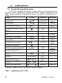
1
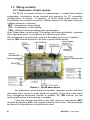
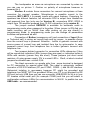
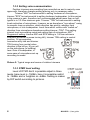
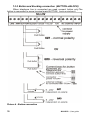
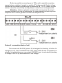
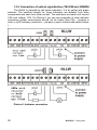
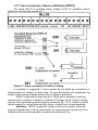
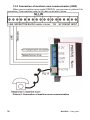
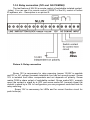
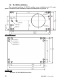
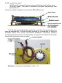
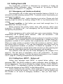
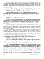
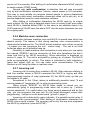
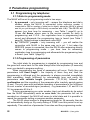
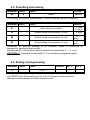
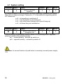
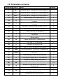
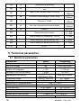
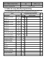
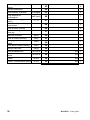
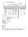
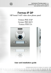
ALPHATECH TECHNOLOGIES s.r.o. Jeremenkova 88, Praha 4, Czech Republic www.alphatechtechnologies.cz New Link Lift Watch Lift communicator User guide Welcome The Link Lift Watch is designed for emergency call from lift to first aid ( service department, police, etc… The NLLW is certained for 1 lift cabin. It is connectable to analog PSTN line or analog extension of PABX. The NLLW is powered from telephone line – the features reminds hands free phone. It is completely independent on lift power supply.The signalization as same as status detection only requires connection of external power supply. All inputs even outputs are galvanically isolated from telephone line. The button as same as control („third“) wire only is connected with telephone line. The NLLW has adjustable parametres saved in internal memory. The parametres might be programmed either by phone via tone (DTMF) dial or by computer PC via configuration software. For connection the NLLW to PC you have to use special cabel. After button pressing the NLLW enables to make phone call up 6 numbers max 16 digits in tone or pulse dial. It is possible also dial “ * ”, “ # ”, Pauze and Flash in tone dial. The button activation might be blocked by input BLOCK. As follow NLLW enables to make a call in case of change the status at input INPUT (failure). The NLLW also provides automatic phone call from systém time clock to confirm its functionality. At all numbers is possible to use mode with or without confirmation. After confirmation of phone call by called party the NLLW reply by its seriál number and current call is taken as accepted. It means that NLLW not dial any other number saved in memory. The next feature is remote control of relay in connection with NLLW by 2 digit code. The switching contact of relay is isolated from the outstanding components. It is very useful feature for example : LIFT RESET . 2 NLLW 50 – ‚User guide Content 1 BASIC DESCRIPTION..................................................................................................... 4 1.1 FEATURES ................................................................................................................... 4 1.2 TERMINOLOGY ............................................................................................................ 5 1.3 WIRING CONTACTS ...................................................................................................... 6 1.3.1 Description of basic module .................................................................................. 6 1.3.2 Setting voice communication ................................................................................. 8 1.3.3 DTMF level setting ................................................................................................ 8 1.3.4 Telephone line connection (LINE a b) ................................................................... 9 1.3.5 Button and blocking connection (BUTTON a BLOCK) ...................................... 10 1.3.6 Connection of optical signalization (YELOW and GREEN) ................................ 12 1.3.7 Input connection- failure notification (INPUT) ................................................... 13 1.3.8 Connection of machine room communication (3WR) .......................................... 14 1.3.9 Relay connection (12V and NC/COM/NO) ......................................................... 15 1.4 NLLW INSTALLATION............................................................................................... 16 2 LLW SERVICE ............................................................................................................... 18 2.1 THE NLLW SIGNALLING TONES ................................................................................. 18 2.2 CALLING FROM LLW ................................................................................................ 19 2.2.1 Emergency call (button activation) .................................................................... 19 2.2.2 Calling from INPUT - Failure call .................................................................... 19 2.2.3 Calling from INPUT - Technical call ................................................................ 20 2.2.4 Service calling ( from timer)................................................................................ 20 2.2.5 End of calling – call confirmation ....................................................................... 20 2.2.6 Machine room connection ................................................................................... 21 2.2.7 Incoming call ....................................................................................................... 21 3 PARAMETRES PROGRAMMING .............................................................................. 22 3.1 PROGRAMMING BY TELEPHONE: ................................................................................. 22 3.1.1 Enter to programming mode ..................................................................................... 22 3.1.2 Programming of parametres ..................................................................................... 22 3.2 PC PROGRAMMING– PROGRAMM LIFT SET ................................................................ 23 4 PARAMETRES DESCRIPTION ................................................................................... 24 4.1 PHONE NUMBERS MEMORY ........................................................................................ 24 4.2 OPERATION ............................................................................................................... 25 4.3 BASIC PARAMETRES ................................................................................................... 26 4.4 TIME PARAMETRES .................................................................................................... 28 4.5 PRESETTING AND ERASING ......................................................................................... 31 4.6 ENDING OF PROGRAMMING ........................................................................................ 31 4.7 SYSTEM SETTING ....................................................................................................... 32 4.8 PARAMETERS OVERVIEW ........................................................................................... 33 5 TECHNICAL PARAMETRES ...................................................................................... 34 5.1 ELEKTRICAL PARAMETRES ......................................................................................... 34 6 TABLE FOR EASY NLLW PROGRAMMING ........................................................... 35 1 Basic description 1.1 Features The unit is powered from line only (you connect line and button only!) The unit includes acoustic part ( micro and speaker) – compact solution! The loudness of micro as same as speaker is adjustable independently Programming is either remotely by phone (DTMF tones) or by PC (serial port RS232 with RS232 cable or USB with USB cable) It includes switchable relay contact . You can control remotely by phone. You can use it for remote control of the lift ( RESET). The time of relay closing is adjustable from 1 to 99 seconds. It includes indication light (LED or bulb -switch) – yellow, indication of dialling the number (powered from 12-24V) It includes indication light (LED or bulb -switch)–green,indication – connection was established (powered from 12-24V) The time of button activation is adjustable from 0,5 sec to 5 sec BUTTON might be connected parallely (switch on puschbuttons) or serial (switch off puschbuttons) to wire up to 100m. Input is optocoupler independent of polarity and you select 3 mode. First mode is current loop powered from 12-24V, second mode is using only if you haven't power supply, then you use power for current loop from telephone line – CAUTION !! It is not galvanically isolated. Third mode is external power - for example: button connection parallely to sirene (powered 12-24V) The possibility of activation via third wire from „ transffer tool“ for communication with machine room BLOCK - security against disusing of alarm buttons (activation during failure 5-24V). INPUT - it includes universal input which you can use for failure announcement ( doors, power supply, etc..) You can programm special phone number . All inputs as same as outputs are galvanicaly isolated – not depends on polarity. ( except button and third wire for machine room). Acoustic as same as optical signalling of NLLW status The possibility to programm 6 numbers ( 16 digits – includes *,#,Pause,Flash) with note if you want use confirmation or not .The numbers are progressivelly dial. Regular automatic control of system functionality ( automatic calling to preprogrammed numbers in set time period from 1 to 10 days) The possibility programm code for remote activation or unactivation of LLW Adjustable level of DTMF dial -6dBm to -14dBm Possibility connect 1-3 microphones (attention on polarity of electret microphone) and posibility connect 1-3 speakers 4 NLLW 50 – ‚User guide Differences between version A and version B version B makes it possible connect only 1 microphone and 1 speaker version B hasn't relay (remote switch) and INPUT (failure announcement) version B hasn't adjustable level of DTMF and has fix -10dBm 1.2 Terminology It is explain here the meaning of used words in manual. Communicator LLW - it is final product designed for communication from lift cabin to service center. Emergency call - it is person calling while lift failure or other emergency situation happened. It is activates by button pushing. The call is being between lift cabin and service center. Service calling - it is calling regularly repeated. (for example every 3 days). It is automatic proving of NLLW functionality. ) Failure calling - it is calling caused by status change on input INPUT Machine room call - it is calling between lift cabin and machine room, ) Incoming call - it is calling coming from outside into NLLW unit. The NLLW pick up (you can programm parametres) Dial - it is kind of dial on telephone line – dial (DTMF) dial (dial even acknowledgement * and # , use loop interuption = Flash) or pulse – (dial only numeral) Telephone line - PSTN line (public line) (line coming directly from Telecommunication carrier) or extension line (coming from PBX) confirmation - dial of combination star * and numerals. After dialling of those characters the call is authorised and lift communicator reply by its unique serial number. (5 digits) serial number - each lift communicator NLLW has unique seriál number since 00001 to 65535. This number is sending via DTMF every time when NLLW receives confirmation character call connection - this status is indicated via lighting of green check – light and might be caused either by call confirmation ( dial confirmation character) or when is not present ringing tone for longer time period. 1.3 Wiring contacts 1.3.1 Description of basic module The NLLW is compact solution of communicator, it means that contains loudspeaker, microphone, screw terminal and connector for PC connection (configuration). At picture 1 is drawing of NLLW basic board (version A). Functionality of connection is explain in follow chapters. On the basic board are 3 setting elements ( trimmers) : MIC – microphone volume setting VOL – loudspeaker volume setting TRH – setting of balance between micro and speaker Note: Please take in mind during TRH setting that incoming direction ( speaker) and outgoing direction ( microphone) are influence each other. We recommend to dont set high volume in the begining of micro or speaker and via TRH set both direction to be both in good volume quality. Picture 1: NLLW basic board For explanation: when signal into speaker approach certain level then decreases micro volume to enter signal into speaker. At the other hand signal from microphone decreases volume of speaker. By TRH trimmer you are setting prefferention of microphone or speaker. Here you can see that when is set high volume of microphone (MIC) as same as speaker (VOL) then signals influence each other. The result might be that call is interrupted or one direction is silent. 6 NLLW 50 – ‚User guide The loudspeaker as same as microphone are connected by wires as you can see on picture 1. Caution on polarity of microphone because is powered (+ -). Version A contain three connectors for connect microphone a three conectors for connect speaker. Microphones is possible conect to the conectors MIC1..MIC3 it is paralel inputs with same features. Conectors for speakers has diferent features, left connector SPK is output from HandsFree and powered from line (only one for Version B), connectors SPK1..SPK2 is output from 1W amplifier powered from 12-24V connection (only version A). The jumper marked SERVICE is available for automatic enter to programming mode when password is forgotten. When jumper is ON And you make incoming call on NLLW then after picking up you are directly in programming mode. In programming mode you can change all parametres includes new password as well. Connection of Button (emergency call) and connection of Input (Error or Technical call) is wiring as current loop and by jumper is possible choice from the current loop is powered. Attention - button is galvanic connect with source power of current loop and isolated from line by optocoupler. In case powered current loop from telephone line is button galvanic connect with telephone line. Two jumpers behind connector for connection LEDs determine if they will be connection indication LEDs (jumers they are open) or indication bulbs or LEDs with resistor (jumers they are short). These jumpers just short serial resistors. At using power supply 12V is current LED c. 10mA, at short-circuited jumpers be allowed max. current 0,5A. The black connector on oposite side from screw terminal is designed for PC connection by special cabel KAB. The cabel is galvanicaly isolated convertor of RS 232 interface (PC port COM1, COM2…) and NLLW interface. Galvanical isolation is neccessary because PC might be grounded and telephone line MUST NOT be grounded! When your PC is not equiped by RS 232 port but only USB then you can use convertor USB-RS232 for its is in your PC creates virtual seriál port (for example COM6) and this you will select in configuration software LiftSet for communication to NLLW. Is posible too use USB cable - we recommended. 1.3.2 Setting voice communication Position trimmers are presetting from manufacture and in majority case agree with, therefore changes setting altering only in necessary case. Trimmer "MIC" be instrumental to setting loudness of microphone, trimmer "SPK" be instrumental to setting loudness loudspeaker. In this version is big reserve in gain, therefore isn't recommended adjust more than on half, typical is in 1/3 from minimum gain. Trimmer "TRH" be instrumental to setting levels activation of microphone, it means, so as doorphone "non whoop" owing to acoustic loop so selection, which direction has priority, whether from microphone, or into loudspeaker. Level from which volume with "switch on" direction from microphone doorphone setting trimmer „TRH". This setting interact level surrounding noise and setting gain of microphone „MIC". Progress of setting: trimmer MIC and SPK setting in 1/4 from minimum loudness (minimum is sense turning left), trimmer TRH setting in central position. At conversation connection stilly talk and trimmer TRH turning from central value direction to the left so, till you will on the side phone (in building) hear. Gain of loudspeaker, in some case of microphone set-up according to needs. Picture 2: Typical range and sense of rotation trimmers 1.3.3 DTMF level setting Level of DTMF dial it is possible adjust in three levels, base level is -10dBm, here it is possible restrict to -14dBm and or heighten on -6dBm. Setting is makes by DIP switch according to pictures. 8 NLLW 50 – ‚User guide 1.3.4 Telephone line connection (LINE a b) The basic condition for NLLW operation is telephone line connection. Telephone line is 2 wires which you connect to screw terminal up picture 3. Picture 3: Telephone line connection Telephone line interface has following typical parametres. The voltage in Hang up status (disconnect loop) 20-60V = (during connection not depends on polarity), when NLLW pick up (active status) on telephone line is cca 7-12V, depends on line current which is in range 20-60mA. Further telephone line parametres are signalling, ringing (incoming call) is define by AC voltage from 50-90V and frequency 20 – 60Hz. To the signalling belongs even tones, have frequency 425Hz +/- 20Hz and level -10dBm (cca 0,22V) and difference lis cadency. The NLLW reacts on those tones. 1.3.5 Button and blocking connection (BUTTON a BLOCK) When telephone line is connected we need connect button only.The button is connected to screw terminal mark BUTTON. Look on picture 4. Picture 4 : Button connection 10 NLLW 50 – ‚User guide Button is possible connecting up to 100m and is possible conecting moore butons „switch on“ paralel or „switch off“ buttons serial. Control of type buttons use is possible programming by parameter 6# 1 or 0. System of push button is wired in current loop and by jumper is select from is loop powered. Attention - button is galvanic connect with source power of current loop and isolated from line by optocoupler. In case powered current loop from telephone line is button galvanic connect with telephone line. Picture 5 : connection block of call The screw mark BLOCK (picture 5) is designed for blocking of button for emergency call. Input is isolated from other parts of NLLW and not depends on polarity. In configuration you can select if BLOCK input is activated by leading of voltage 5-24V or by disconnection of this voltage. 1.3.6 Connection of optical signalization (YELOW and GREEN) The NLLW is equiped by call status indication. It is by yellow and green indicator. The switcher outputs for those indicators are isolated from other components and each from other as well. The switchers are made until current 0,5A and voltage 50V. On Picture 6 you can see examples of lamp indicator connection (power consumption should not be higher than 5W) – jumpers is short or LED indicator connection – jumpers is open (internal add seriál resistor ). Picture 6: Indicator connection 12 NLLW 50 – ‚User guide 1.3.7 Input connection- failure notification (INPUT) On screw INPUT is possible leads voltage 5-24V for activation failure calling as you can see on picture 7. Picture 7: Input connection for failure calling Is possible to programm if input should be activated by connection or disconnection of voltage on this screw. As next parameter you programm the lenght of this voltage change before failure calling is activated. INPUT is possible connecting up to 100m and is possible conecting moore butons „switch on“ paralel or „switch off“ buttons serial. Control of type buttons use is possible programming by parameter 6# 1 or 0. System of push button is wired in current loop and by jumper is select from is loop powered. Attention - INPUT is galvanic connect with source power of current loop and isolated from line by optocoupler. In case powered current loop from telephone line is button galvanic connect with telephone line. 1.3.8 Connection of machine room communication (3WR) When use in machine room modul PREPOJ you can see on picture 8 its connection. From machine room to lift cabin must lead 3 wires. Picture 8: Connection of machine room communication 14 NLLW 50 – ‚User guide 1.3.9 Relay connection (12V and NC/COM/NO) The last feature of NLLW is remote control of switchable isolated contact (relay). You can use it for remote control ( RESET of the lift), control of further lift systems, etc… Description is on picture 9. Picture 9: Relay connection Screw 12V is neccessary for relay powering (power 12-24V is possible and DC or AC voltage) because telephone line has not enough power. Screw 12V is isolated from other components and not depends on polarity. Screw marks COM is share output of switchable contact. Screw marks NO ( normaly open) the contact in stand by is OFF and screw marks NC (normaly close) the contact in stand by is ON. In configuration you can programm code and time for relay switching. Screw 12V is neccessary for LEDs and for correct function circuit for push button(s). 1.4 NLLW Installation The compact solution of NLLW enables easy installation into lift cabin panel. Dimension and installation holes are descriped on picture 10. SPK-MIC panel NLLW unit Picture 10: NLLW50 dimension 16 NLLW 50 – ‚User guide NLLW contains two parts: - NLLW unit it's meanns Top cover and motherboard and bottom cover - SPK-MIC panel - this panel is possible by screews mechanicaly fixed with NLLW unit Version A makes it possible connect three SPK-MIC panels. The lift cabin panel should be equiped by acoustic holes in microphone as same as speaker part. It should be also provides by 4 screws M4 for fixing the SPK-MIC panel. The proper mechanical installation essentially influence acoustic parametres of the unit. Particularly microphone and speaker should be fixed tightly to acoustic holes in panel. Attention: microphone has polarity- red is + !!! 2 LLW service 2.1 The NLLW signalling tones The NLLW signalling acousticuly stages which can happened during operation. Further signalling is by Green and Yellow indicator connnected in lift cabin. Acoustic samples of signalling tones you can check in configuration sw LiftSet. Stage Tones frequency Indicators Line pick up –▄–■–▀– 425-850-1275 Yellow lighting Line hang up –▀–■–▄ 1275-850-425 Light off Notification after calling –▄–■–▀– 425-850-1275 Green lighting ––█–– 425 Command confirmation from phone Dial DTMF/Pulse Light off Call lighting x Notification of call ending –■–■–■– 1275 Enter to programming mode from phone –■–■–■– 850 ––▓–▓––––– mod. 850 Programming from phone Enter to programming from PC –■–■–■– 850 –■–▄–■– 1275-8501275 Programming from PC Connection to telephone line (Reset) Empty memory (not programmed number) Calling from input INPUT (failure) Calling from system timer Yellow lighting Yellow lighting ––█–– Parameter confirmation ERROR lighting x Sequentialy flashing Sequentialy flashing Both flash –■–■–■–■–■–■– 425…. –█–▄–■–▄–■–▄– 850-12751700… –▓–▓––––▓–▓– Mod. 850 Lighting off –▓–––––––––▓– Mod. 850 Lighting off lighting x – green / yellow – up stage (confirmed = green) Table 1 : Signalling used in LLW 18 NLLW 50 – ‚User guide 2.2 Calling from LLW The functionality of NLLW is influenced by connection of further lift components (failure notification, relay,...) as same as by setting of NLLW parametres (via. chapter 4 – P / page24). 2.2.1 Emergency call (button activation) The emergency call is basic and most important feature of NLLW. It is activated by button pressing (screw BTN). To provide correct functionality you must keep 2 conditions: First condition is that , button blocking is not active. Please note that blocking might be either by leading voltage 5-24V or by disconnection this voltage. Second condition is that button you must hold enough time. It is adjustable from 0,5 sec to 5 sec. Button pressing has priority before other calls (service, failure even incoming). If is being a call ( not emergency) the call is stoped and starts emergency call procedure. During emergency call is active both way voice communication. During establishing call is lighting yellow indicator . After call connection – call confirmation – green indicator light up. Emergency call dial progressivelly stored numbers (1÷6 position). It starts from position 1 up to position which is not programmed. It means when you programm numbers to all 6 position then progressivelly dial all 6 numbers. When you erase number on position 3 then dial numbers on position 1 and 2 and returns back to position 1. You can also programm how many times the round (programmed numbers on position 1-6 should be repeated ( 1 to 5 times). While is emergency call the button does not react on other pressing and even more any other stage might not break emergency call procedure. The machine room call only can break emergency call (chapter 2.2.6 page.21). The last point of emergency call is call confirmation . At every emergency number ( position 1-6) you can select confirmation or not. (chapter 2.2.5 – page.20.). Dialling is stoped after call connection. 2.2.2 Calling from INPUT - Failure call Calling from activated input INPUT is named failure calling - set parameter 391. The NLLW enables to make notification about lift failure for service department. The call is activated by voltage change ( 5-24V ON/OFF) on input INPUT. It is adjustable in setting. As follow you can select time how long must be change on input INPUT to start failure calling. Failure calling has own number which might be of course the same as emergency or service call number. You can also select if will be dialling only this number or all round of emergeny numbers ( then you have max 7 numbers) . Failure calling is not repeated. It means that all numbers are calling only once And then NLLW hang up. Further round might be activated only by new change on input INPUT. The voltage must returns back to stand by mode. The change on input INPUT must happen again. During failure calling are all other features available. During failure calling is not lighting any indicator. It is not voice communication. The call is generating beeps – via. Table 1 page. 18. 2.2.3 Calling from INPUT - Technical call Calling from activated input INPUT is named technical calling - set parameter 390. This call is acoustic - possible talking and indication LEDs is like as Emergency call. Telephone number and other features is same like as failure call. 2.2.4 Service calling ( from timer) Service calling is optional parameter. You alsé define if this parameter is activated since first connection of NLLW to telephone line.This service calling is adjustable from 1 to 9 day period, for example 3 means that NLLW is make automatically every 3th day a call to preprogrammed number. (test of NLLW functionality). For service calling you programm special number which might be of course the same as emergency or failure calling number. You can also select if will be dialling only this number or all round of emergeny numbers ( then you have max 7 numbers) . The service calling is repeated in period 0-9 min ( programmable) until succesfull call ( confirmation). The repeated time between calls is programmable because to service department can call more NLLW. To avoid of problem that service department line is busy you can programm different time period for service calling up installation place. During failure calling is not lighting any indicator. It is not voice communication. The call is generating beeps – via. Table 1 page. 18. 2.2.5 End of calling – call confirmation The NLLW enables to programm at every number if will be confirm or not. Every call needs authorisation if it was succesfull or not. Therefore analog line doesnt support any kind of authorisation (signalling) we can define success of call by 2 ways. The NLLW needs this info to not dial further numbers. First way (no confirmation) is detection that call was succesfull on the base control ringing tone (CRT). It is tone which we are hearing in handset when make call to other subscriber. Thed NLLW detects this tone And when is missing for certain time then evaluate the call was succesfull (Green indicator light up and yellow light down). The time which define undetection of CRT ( called part picks up) is adjustable because each type of PBX can be different. Usually should be 5 seconds as the best. At this call authorisation stays possibility confirm the call by dial confirmation characters (*xxxxxx, where 20 NLLW 50 – ‚User guide xxxxxx is 2-6 numerals). After dialling of confirmation characters NLLW reply by its serial number (DTMF tones). Second way (with confirmation) is detection that call was succesfull only by dial confirmation characters (*xxxxxx, where xxxxxx is 2-6 numerals). This way is most reliable but requires trained people in service department (they must be able insert confirmation characters when call is pick up), or at service department must be used evaluation software. After dialling of confirmation characters the NLLW reply by its unique serial number. By this way is detected where from is coming a call even when more NLLW is installed behind PBX. In this case is not possible detect it by CLIP because all NLLW have the same CLIP due the same telephone line use for outgoing calls. 2.2.6 Machine room connection Connection between machine room and NLLW is special case which has absolut priority. The reason is that during machine room communication is disconnected telephone line. The NLLW accept machine room call as incoming , it means you can programm the unit , control relay,.. The call is not time limited as same as not possible hang up. Possibility to make machine room connection is only when you use option box named „PREPOJ“ and via connection of third wire (telephone line has 2 wires And third is for NLLW controlling). Wires connection is displayed on picture 8, page 15. The call is activated by picking up of phone. The NLLW picks up immediatelly (is active). This status is indicated by both indicators ( green and yellow) light up. You can make voice communication. The call duration is until hang up phone in machine room. 2.2.7 Incoming call Incoming call is coming from outside to NLLW. After extension dialling or land line number where is NLLW connected the NLLW is ringing and after preprogrammed number of rings (parameter 51) the NLLW picks up And you can speak to lift cabin. Exceptional is first 10sec, where is additionally possible insert "# and service password" (parameter 44), to enter programming mode. When jumper "SERVIS" on NLLW basic board is closed you are automatically going to programming mode when call is picks up. ( without service password). It is usefull when you forget service password and by this way you can programm the new one. Do not forget disconnect jumper after programming . Jumper is on the basic board (picture 1 page 7). Incoming call is detected by green indicator. It is possible control relay. It is possible voice communication. After dialling of confirmation characters the NLLW returns seriál number. The incoming call is only the way how programm the NLLW by telephone (tone dial DTMF). 3 Parametres programming 3.1 Programming by telephone: 3.1.1 Enter to programming mode The NLLW will be set to programming mode in two ways: 1. by password – only incoming call! – answer the telephone and dial a number, where the NLLW is connected (either extension number, if connected to PBX or number of state line to object, where the NLLW is placed and let you put through to PBX directly connected with LLW). The NLLW will answer (you hear tone for answering – see Table 1 page14) up to 10 sec dial #xxxx, where xxxx is the service number for entry to programming and if O.K., the registration tone to programming will sound and afterwards the programming tone is heard (see Table 1 page19). Default setings is password xxxx=0000 2. by "SERVICE" jumper – only incoming call! – you will realize the connection with NLLW in the same way as in art. 1, but when the SERVICE jumper is connected, then the NLLW after answering directly comes to programming mode – you hear tone for answering, registration tone to programming and afterwards the programming tone is heard. (see Table 1 page19). 3.1.2 Programming of parametres The initial state for programming is signaled by programming tone and the guard will come back to this state always after time expiration (5 seconds) even you started to program anything. When programming two types of parameters will occur. Partly they are parameters with fixed length – the majority of them they are, then the programming is affirmed and the parameter is always recorded immediately after mandatory length fulfillment by acknowledge tone and partly the parameters with variable length (parameter 1,21,22,45), followed with confirmation and the recording of the parameter after inactivity period expires (5 sec). The only case with immediate recording of parameters is the fulfillment of max. number of recorded signs (numbers) – by parameters 1,21 and 22 it is 16, by parameter 45 it is 6. If during programming you enter number (sign) not allowable by its extent then the NLLW immediately emits an error tone, the parameter will not be recorded nor changed, the NLLW will come to initial state and it is possible to repeat the parameter setting or program another parameter. The NLLW stays inactive in programming mode for 34 seconds, then he will automatically hang up. By every dialing of DTMF tone this period is set up repeatedly. The selection of parameter 9 can also end the programming mode. 22 NLLW 50 – ‚User guide Note 1. if you wish to keep the connection (extend the 34 seconds period) than the customer will think over the other setting, so pressing e.g.. 6, 7, 0, * or # form time to time will be sufficient and the guard immediately responds by error tone, but he will extend the period to hanging up.. 3.2 PC programming– programm Lift SET For setting of NLLW by PC you need special cabel KAB ( RS 232 port) and Programm Lift SET. The NLLW must be connected to telephone line – powering. Procedure: - Connect the NLLW to the line - Connect the NLLW with PC by KAB cable (if PC serial port absent, the USB-COM reduction is to be used). The NLLW will answer and LED light on the front panel will light. - Run the Lift SET program – the NLLW will report the his conversion to PC programming mode (viz.table 1 page14). After Liftset program being run the NLLW is in this mode – this status is indicated by LED light on front panel by 1 second flashing. By loss of connection it is necessary to disconnect the cable from NLLW connect it again – the NLLW will answer and if Liftset program runs he will report his conversion to programming mode. 4 Parametres description 4.1 Phone numbers memory Emergency numbers (button activation) Parameter Value 1 pt nn… Note default number nn in order p with confirmation t p – Memory order of number, programm [1-6] digits only t – call confirmation, programm [0-1] only, 0-confirmation OFF nn – telephone number up 16 digits. To programm other characters look on table. Basic setting as same as examples setting not change or erase those saved numbers. note 0-9 # * Flash Pause dial 0–9 # ** *# *0 Service number (system timer activation) Parameter Value 21 t nn… Note Default Number nn in order p with confirmation t t – call confirmation, programm [0-1] only, 0-confirmation OFF nn – telephone number up 16 digits. To programm other characters look on table. Basic setting as same as examples setting not change or erase those saved numbers. note 0-9 # * Flash Pause dial 0–9 # ** *# *0 Failure number (input INPUT activation) Parameter Value 22 t nn… Note Default Number nn in order p with confirmation t t – call confirmation, programm [0-1] only, 0-confirmation OFF nn – telephone number up 16 digits. To programm other characters look on table. Basic setting as same as examples setting not change or erase those saved numbers. 24 note 0-9 # * Flash Pause dial 0–9 # ** *# *0 NLLW 50 – ‚User guide 4.2 Operation Parameter 31 Value a Note Default Service calling is in st atus ON / OFF a 0 a – 0 service calling OFF – 1 service calling ON after time set in parameter 56 – 2 service calling ON after time set in parameter 56 and moreover is activated during first telephone line connection service calling is activated after time set in parameter 56 and is repeated after time period set in parameter 36 Parameter 32 Value h Note Default For service calling are used also emergency numbers 0 – 0 emergency numbers are not used. It is calling only number programm in parameter 21 – 1 emergency numbers are used. It is calling numbers programmed in parameter 21 and 1 List of corresponding parametres: 1 21 31 56 36 h Parameter 33 Value i Note Default For failure calling are used also emergency numbers 0 – 0 emergency numbers are not used. It is calling only number programm in parameter 22 – 1 emergency numbers are used. It is calling numbers programmed in parameter 22 and 1 List of corresponding parametres: 1 22 34 38 i Parameter 34 Value z Note Default Activation of failure calling on input INPUT 0 – 0 failure calling is activated by voltage connection 5-24V – 1 failure calling is activated by voltage disconnection 5-24V List of corresponding parametres: 1 21 33 38 z Parameter 35 b Value b Note Default Button blocking - input BLOCK – 0 emergency call is blocking by voltage connection 5-24V – 1 emergency call is blocking by voltage disconnection 5-24V 0 List of corresponding parametres: 1 53 Parameter 36 Value Note Default c 5 Time of service call repeating – 0 ÷ 9 – unsuccesfull service call is repeated after time 0 ÷ 9 minutes. This time is adjustable to repeated service call from more NLLW doesnt come in same time. List of corresponding parametres: 31 56 c Parameter 37 Value d Note Default 1 Number of emergency call sequence repetation – 1 ÷ 5 times is repeated dial of emergency numbers (button pressing). Emergency numbers are dialled from first position until empty or 6th position. This is 1 sequence. It might be repeated max 5 times. List of corresponding parametres: 1 d Parameter 38 Value e Note Default Time of failure duration before failure calling is activated 1 – 0 ÷ 9 is time [sec] of permanent failure duration on input INPUT to be activated failure calling List of corresponding parametres: 22 33 34 e Parameter 39 w Value Note w Default 1 Failure (error) call or Technical call – 0 Technical call - acoustic with indication – 1 Failure (error) call - special beep, mute and without indication LED 4.3 Basic parametres Parameter 41 Value v Note Default Dial type v – tone / pulse 0 v – dial type v=0 DTMF tone dial v=1 pulse dial List of corresponding parametres 1 21 22 26 NLLW 50 – ‚User guide Parameter 42 Value Note z Default * Character for prolonging of call z – character for prolonging of call * or # (10sec before end of call the NLLW send notification tone – you can prolong the call by pressing character List of corresponding parametres: 52 Parameter 43 Value bb Note Default 44 Code for hanging the NLLW from phone bb – code for hanging the NLLW from phone [2 digits] List of corresponding parametres: 52 Parameter 44 Value xxxx Note Default 0000 Service password ( during dial in advance #) xxxx – service password for enter to programming mode List of corresponding parametres: 8# 84 Parameter 45 Value yyyyyy Note Default 66 Confirmation character (during dial in advance *) yyyyyy – confirmation character is numerals combination - from 2 to 6 numerals List of corresponding parametres: 1 21 22 Parameter 46 Value c Note Default 5 Time waiting for confirmation cx5 [sec] c – 5 ÷ 50 sec (0 = 50 sec) is time which after number dialling the NLLW waiting for call confirmation. It is calculate that value c ( number dial from phone during programming) is x 5 . List of corresponding parametres: 1 21 22 45 Paramete r 47 Value e Note Time without ringing tone – call detection Default 5 e – 1 ÷ 10 sec (0 = 10 sec) is time for which is not detected ringing tone after dialling of number. If is set at number dial without confirmation then is set that call started. List of corresponding parametres: 1 21 22 Parameter 48 Value rr Note Default 55 Code rr for switching relay from phone rr - code for switching relay from phone (2 digits) List of corresponding parametres: 49 Parameter 49 Value Note ss Default 05 Time of relay switching ss [sec] ss - time [sec] of relay closing after dialling of code from phone (2 digits) List of corresponding parametres: 48 4.4 Time parametres Parameter 51 Value q Note Default Number of rings before NLLW picks up the call 2 q – number of incoming call rings. The NLLW picks up always between rings. It is 2 seconds after detection q – th rings. The number is adjustable from 1 to 9. List of corresponding parametres: 44 Parameter Value 52 Note d Default 2 Max call duration d – max time when NLLW is OFF HOOK. This time is possible change during a call by dial appropriate character from phone (* or #). Programming of time is up table. List of corresponding parametres: 42 Parameter Value 53 w w Note Dial 0 1÷9 * # time 0,5 min 1÷9 min 15 min 30 min Default Time of button pressing (holding) for emergency call activation 2 – min time for which must be button hold pressed to start emergency call procedure. The calculation is (w x 0,5) + 0,5 sec, it means 0=0,5sec, 3=2sec…. 9=5sec List of corresponding parametres: 1 28 NLLW 50 – ‚User guide Parameter Value 54 Note z Default Hanging up time during redial 2 z – is time [sec] for which the NLLW hangs up before dialling next number – not confirmed call or called part is busy , etc... [range 1-5 sec] List of corresponding parametres: 8# 85 Parameter Value 55 Note y Default Time before number dialing 1 y – is time [sec] after picks up the line and dialling the number [range 1-5 sec]. This time is different for each PBX type but usually all PBXs works with time up 2 seconds. List of corresponding parametres: 8# 85 Parameter Value 56 h Note Number of days after which is perform service call Default 3 h – [1 ÷ 9 days] after programmed time in parameter 21 eventually parameter 1 the NLLW call to service department to notify its full operation ( functionality). The time from last call is display in Lift set programm. List of corresponding parametres: 31 32 36 45 Parameter Value Note Default 57 t The time of DTMF dial (tone) duration 58 m The time of space between DTMF tones 59 f The time of Flash 50 p The time of pause /internumeral space 5 (100ms) 5 (100ms) 1 (100ms) 8 (800ms) – the time of tone duration is calculate: (insert number + 5) x 10 = tone duration time [ms] [range 1-0 , it is 60-150ms] m – the time of space between tones is calculate: (insert number + 5) x 10 = space duration time [ms] [range 1-0, it is 60-150ms] f – the time of Flash is calculate: insert number x 100 = Flash duration time [ms] [range 1-6, it is 100-600ms] p – the time of pause is calculate: insert number x 100 = pause duration time [ms] [range 5-0 , it is 500-1000ms] – time p is simultaneously time of internumeral space in pulse dialling t List of corresponding parametres: 1 21 22 serial number sending 30 NLLW 50 – ‚User guide 4.5 Presetting and erasing Parameter Value 8# Note Default # perform default This setting not influence parametres 1 and 2 (numbers saved in memory) Parameter Value Note Default 81 Erase all phone numbers 1.. and 2..only 83 Default setting for parametres 3x only 3..only 4.. only 5.. Default setting for parametres 5x only 85 only Parameter 81 perform erasing of all numbers saved in memories of emergency, service and failure call. Parametres 83 – 85 perform selected default for parametres 3.. – 5.. only CAUTION !!! erasing is unreturnable !!! It is neccessary programm again. 84 Default setting for parametres 4x only 4.6 Ending of programming Parameter Value 9 Note Default Ex. 1 Ex. 2 END After 9 dial into programing tone the NLLW hangs up. When programming is via PREPOJ box from machine room it is not hangs but returns back to standard communication lift cabin-machine room. 4.7 System setting Parameter Value 6 z Note switch off acoustic signalling Default 3 Ex. 1 Ex. 2 3 3 By default is status of communicator acoustic signalling, it however can cause false dial at cheap exchange. Parameter „z" it is possible this signalling switch off. Values are: z=0 – all signalling is switched off z=1 – only tones pick up and hang-up z=2 – only other tones (except pick up and hang-up) z=3 – all tones they are switched on Parameter Value 6# p Note polarity input buton of emergency call Default 1 Ex. 1 Ex. 2 1 1 Normal polarity of emergency buton is switch on by pushing buton, opposite polarity is switch off by pushing button. p=1 – normal polarity - activate by switch on p=0 – opposite polarity - activate by switch off Attention: for correct function of push buton is necesary connect power supply 12V 32 NLLW 50 – ‚User guide 4.8 Parameters overview Parameter Value 21 pt nn… t nn… 22 t nn… 31 a 1 Note Default Number nn in order p with confirmation t - Number nn in order p with confirmation t - Number nn in order p with confirmation t - Service calling is in status ON /OFF 0 For service calling are used also emergency numbers For failure calling are used also emergency numbers 32 h 33 i 34 z Activation of failure calling at input INPUT 0 35 b Blocking of button by input BLOCK 0 36 c Time of service call repeating 5 37 d 38 e 39 w Failure (error) call or Technical call 1 41 v Dial type v – tone/ pulse 0 42 z Character to prolong a call * 43 bb Code for NLLW hanging up from phone 44 44 xxxx Service password (during dial in advance #) 0000 45 yyyyyy Confirmation character (during dial in advance*) 66 46 c Time waiting for confirmation cx5 [sec] 5 47 e Time without ringintg tone – call detection 5 48 rr Code rr for relay closing from phone 55 49 ss Time of relay closing ss [sec] 05 51 q Number of rings before NLLW picks up incoming call 2 52 d Max call duration 2 53 w Time button pressing (holding) for activation emergency call procedure 1 54 z Hanging up time when is redial 2 Number of repeating the emergency call sequences The failure time duration before activation of failure calling 0 0 1 1 55 y Time before start dialling 1 56 h Number of days,after this time make service call 3 57 t Tone (DTMF) duration time of tone dial 58 m The time of space between DTMF tones 59 f The time of Flash 50 p The time of pause /internumeral space 8# # Default 5 (100ms) 5 (100ms) 1 (100ms) 8 (800ms) 81 Erase all phone numbers 83 Default setting for parametres 3x only perform 1.. and 2.. only 3..only 84 Default setting for parametres 4x only 4..only 85 Default setting for parametres 5x only 5.. only 9 END 5 Technical parametres 5.1 Elektrical parametres Parameter Min line current Min line voltage Line voltage when is NLLW OFF HOOK (VA diagram) Ground in ON HOOK status Impedance line ending Frequency range Ringing impedance Sensitivity of ringing detection Pulse dial Tone dial level Tone dial sensitivity Tone detection sensitivity Powering for relay control Max consumption for relay 34 Value Conditions 18mA Line OFF HOOK 18V Line ON HOOK < 8V I = 20mA < 12V I = 60 mA < 50uA U = 60V 130R + Line OFF HOOK 820R paral. 220n 300Hz – 3400 Hz 20 - 60mA > 2Kohm 25 – 60 Hz min. 10 – 25 V 40 / 60 ms -10 a -8 dBm 20 – 60 mA 40 dB 20 – 60 mA 30 dB 20 – 60 mA 12Vss ± 2V , 10-12Vst ± 2V 50mA 12Vss NLLW 50 – ‚User guide powering Max. voltage of relay contact Max. current of relay contact Operation temperaturte 48V 2A when I < 1A when U < 30 V - 20 to + 50 st 6 Table for easy NLLW programming To empty parts of table write values of parametres which you want to be programmed.Moreover the values stays in manual for future changes. Note description Emergency number position 1 Emergency number position 2 Emergency number position 3 Emergency number position 4 Emergency number position 5 Emergency number position 6 Service call number Failure call number Service call switch ON For service call use emergency numbers For failure call use emergency numbers Activation of failure call INPUT Blocking of button activation Time of service call repeating Number of emergency call sequences repeating Time of failure duration Dial type tone/pulse Character to prolong a call Programming procedure detail Confirm 1/0 Confirm 1/0 Confirm 1/0 Confirm 1/0 Confirm 1/0 Confirm 1/0 Confirm 1/0 Confirm 1/0 0/1/2 par. Write values digi ts 11 16 12 16 13 16 14 16 15 16 16 16 21 16 22 16 31 1 1/0 32 1 1/0 33 1 1/0 34 1 1/0 35 1 1–0 36 1 1–5 37 1 0–9 38 1 1/0 */# 41 42 1 1 LLW hanging up from phone Service password Confirmation character Time waiting for confirmation Time without ringing tone (call?) Code for relay switching from phone Time of relay closing Number of rings before picks up Max call duration Time of button holding Hanging up time when is redial Time before starts dialling Service call time Tone duration time Space duration between tones Flash Pause / internumeral space 36 43 2 44 45 4 2-6digits cx5 [sec] 46 1 1–0 47 1 48 2 49 2 51 1 52 53 1 [sec] [sec] 54 1 [sec] 1 (n+5)x10 55 56 57 ms 1 (n+5)x10 58 ms 1 nx100 59 50 ms 1 ms 1 [min] [dny] nx100 6 1 1 NLLW 50 – ‚User guide Picture 11: Example of connection with LED, blocking and failure is activated by voltage connection, machine room communication ALPHATECH TECHNOLOGIES s.r.o. Jeremenkova 88, Praha 4, Czech Republic www.alphatechtechnologies.cz ALPHATECH TECHNOLOGIES s.r.o. Jeremenkova 88 140 00 Praha 4 Czech Republic VAT: CZ27577350 Company is registered in the Commercial Register administered by the Municipal Court in Prague, Section C, Record 116886 Banking details: Komerční banka, account No. 43-7671450207/0100 IBAN: CZ0801000000437671450207 SWIFT: KOMBCZPPXXX