1
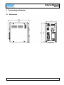
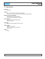
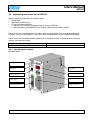
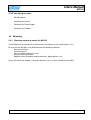
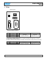
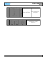
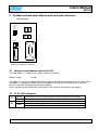
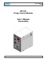
User’s Manual
MC100
MC100
Pump Control Module
User’s Manual
(DeviceNet)
MC100 DeviceNet OM 1.15 EN
Version: 1.04
Page 1 of 43
Users Manual
MC100
CONTENTS:
1
Introduction..............................................................................................................................4
1.1
Abbreviations in this manual ....................................................................................................4
1.2
Precautions .............................................................................................................................4
2
General description of MC100 .................................................................................................5
2.1
Overview .................................................................................................................................5
2.2
Introduction & design purpose .................................................................................................5
2.2.1 How it works / Technical description of operation ....................................................................5
2.3
Flexicon pumps used in multi-filling system, short description. ................................................6
2.4
How to operate the dispenser pumps ......................................................................................7
3
Technical specifications ...........................................................................................................8
3.1
Dimensions..............................................................................................................................8
3.2
Specifications ..........................................................................................................................9
3.3
Unpacking and inspection of MC100 .....................................................................................10
3.3.1 Identifying the module............................................................................................................10
3.3.2 Identifying the parts ...............................................................................................................11
3.4
Mounting................................................................................................................................11
3.4.1 Choosing a place to mount the MC100 ..................................................................................11
4
Wiring ....................................................................................................................................12
5
Fieldbus network node address and front plate indicators .....................................................14
5.1
Network node address switches S1/S2: .................................................................................14
5.2
P1/P2 LED indicators:............................................................................................................14
5.3
Display P4/P5 ........................................................................................................................15
5.3.1 Start up states: ......................................................................................................................15
5.3.2 Network address....................................................................................................................15
5.3.3 Alarm- and warning display ...................................................................................................15
5.3.4 Dipswitch ...............................................................................................................................15
6
Configuring the fieldbus network to the MC100 .....................................................................16
6.1
Connecting the MC100 and the pumps for the first time ........................................................16
6.2
Configuring the DeviceNet network........................................................................................17
7
Operating the MC100 ............................................................................................................18
7.1
Process Data Exchange (Cyclic data)....................................................................................18
7.1.1 Process control bits for MC100 ..............................................................................................18
7.1.2 Modes: ..................................................................................................................................18
7.1.3 Process status bits from MC100 ............................................................................................20
7.1.4 Process control bits for the pumps .........................................................................................21
7.1.5 Process status bits from the pumps .......................................................................................22
7.2
Operation Parameters / Parameter specifications ..................................................................23
7.2.1 List of basic ADI’s ..................................................................................................................23
7.2.2 List of additional ADI’s ...........................................................................................................25
7.2.3 Detailed description of the ADI’s ............................................................................................26
8
Alarm and warnings ...............................................................................................................35
8.1
Alarms handling .....................................................................................................................35
8.1.1 Module Alarms.......................................................................................................................35
Pump alarms......................................................................................................................................35
8.2
Warnings handling .................................................................................................................36
8.2.1 Warnings ...............................................................................................................................36
9
Trouble shooting ....................................................................................................................37
9.1
Trouble-shooting....................................................................................................................37
9.2
Opening the MC100 for service/replacement of PCB’s ..........................................................39
10
Decommissioning ..................................................................................................................40
10.1
Advice about dismantling / removal / disposal .......................................................................40
MC100 DeviceNet OM 1.15 EN
Version: 1.04
Page 2 of 43
Users Manual
MC100
10.2
10.3
11
12
12.1
13
Environmental conditions / -regulations .................................................................................40
The WEEE system ................................................................................................................40
Appendix 1 ............................................................................................................................41
Appendix 2 ............................................................................................................................42
Tube tables............................................................................................................................42
Declaration of Conformity ......................................................................................................43
MC100 DeviceNet OM 1.15 EN
Version: 1.04
Page 3 of 43
Users Manual
MC100
1 Introduction
1.1 Abbreviations in this manual
Fieldbus
Fieldbus interface module
Filling system
Pumps
DeviceNet, Profibus, CANOpen etc.
Anybus Compact Com Module from HMS
System consisting of an MC100 and from 1 to 16 pumps
All Watson-Marlow Flexicon pumps types that communicates on Flexnet
WMF
Watson-Marlow Flexicon
1.2 Precautions
This manual should be read thoroughly before using the MC100.
It is strongly advised that
-
No wiring is connect or disconnect on the MC100, while power supply is turned ON
The MC100 must not to be used in explosion hazardous environments.
MC100 DeviceNet OM 1.15 EN
Version: 1.04
Page 4 of 43
Users Manual
MC100
2 General description of MC100
2.1 Overview
MC100 is a Pump control module capable of controlling up to 16 WMF Pumps. The basic function is
to receive filling data from the filling line control system through an industrial fieldbus and to calculate
operating values for the pumps. Transmit/ Receive those values and status through the FlexNet
protocol.
MC100 constitutes with WMF Pumps a filling system that is designed for incorporation into a larger
facility as described below.
Filling system
Recipe
Commands
MC100
Filling line control system
incl. storing of recipe and
HMI
Actual
parameter
Status
Pump
Pump
Pump
Pump
Product
Achieved
fill amount
Scale
2.2 Introduction & design purpose
The MC100 is a small module for mounting inside the control cabinet of the filling line.
It is designed with the purpose of integrating Watson-Marlow Flexicon pumps into a filling line.
2.2.1 How it works / Technical description of operation
Via the fieldbus the MC100 receives operating data from and sending data to the control system for
the filling line. The data are divided in three types:
• General data for the pump system
• Set-up data for each pump
• Operation data for each pump
The MC100 sets up the pump system according to the data received from the control system for the
filling line.
All control and status signals for the individual pumps connected to the MC100 are sent to the MC100
via the fieldbus. The dispensing can also be controlled via hardwired signals. Please see the manual
for the pumps for more details regarding the hardwired signals.
The MC100 cannot store data such as recipes and historical data. These data must be stores in the
control system for the filling line and be transmitted to the pump system when needed.
MC100 DeviceNet OM 1.15 EN
Version: 1.04
Page 5 of 43
Users Manual
MC100
2.3 Flexicon pumps used in multi-filling system, short description.
The Watson Marlow Flexicon multi filling system consists of up to 16 filling dispensers (pumps)
connected via a fieldbus to a MC controller.
The dispensers can be peristaltic dispenser pumps (PD12 and PD22) and gear dispenser pumps
(GD30).
The MC controller can be either a MC12 controller with integrated keyboard and display to enter data
and control the dispensing or MC100 for integration in control systems.
This manual describes the MC100 controller.
The pumps are used for dispensing accurate doses of liquid into vials.
For this purpose there are a number of parameters, which are used to control the pump:
Speed:
The range for the dispensing speed is 30 to 600 rpm depending on the
pump and the tube selected
Acceleration:
The range is 1 to 200 rpm/s depending on the pump and the tube selected.
Reverse (back sucking): Is a figure between 1 and 10 defining a short reverse pumping to prevent
dripping after the dispensing.
Tube:
The pumps hold a tube table of up to 10 tubes, which can be read from the
pumps. The tubes are depending on the pump type. Thus the pump table
can be down loaded from the pump software via the MC100.
Volume:
The volume the pump has to dispense at each filling. Please also see serial
and parallel mode below.
Density:
The density [g/cm3] for the product to be filled. Used when calculating the
calibration value.
Calibration:
The net weight filled during dispensing. When a new volume is defined for a
pump it will dispense approximately 70 – 80% of this volume until
calibrated.
The calibration is normally done by tare weighing a vial, filling it and
weighing it again to calculate the net filling weight. The net weight filled is
sent to the MC100. The MC 100 then calculates the dispensing data and
sends it to the pump in question.
Please see the manual for the pump for further details.
When more than 1 pump is connected to the MC100, it is possible to operate the filling system (MC
100 with pumps) in 3 different operating modes: Individual, parallel and serial mode.
Individual mode:
All the different types of WM-Flexicon pumps can be connected and run
independently for all parameters.
Parallel mode:
This mode requires that all enabled pump are of the same type, i.e. all
PD12; all PD22 or all GD30.
Different pump types can be connected to the MC 100, but only pumps of
the same type can be enabled and operated together in parallel mode.
In parallel mode a virtual pump (pump no. 0) is be used to hold common
parameters for all the enabled pumps. However, the pumps will still have
to be calibrated individually.
MC100 DeviceNet OM 1.15 EN
Version: 1.04
Page 6 of 43
Users Manual
MC100
Serial mode:
This mode requires that all enabled pump are of the same type, i.e. all
PD12; all PD22 or all GD30.
Different pump type can be connected to the MC 100, but only pumps of
the same type can be enabled and operated together in parallel mode.
All pump data, except tube sizes, are stored in the virtual pump (pump no.
0).
The filling volume is divided to the pumps based on the tube sizes.
Calibration for all the pumps is done by calibrating the virtual pump 0.
2.4 How to operate the dispenser pumps
Before a new filling is started the parameters for this filling is loaded to the pumps from the filling
system.
The data are loaded to the pumps either individually or as common data depending on the operating
mode – please see above.
Initially the pumps need to be primed – i.e. the product has to be filled into the tubes and nozzles of
the filling system.
Hereafter the pumps must be calibrated.
For details of priming and calibrating please see the manual for the pumps attached.
During production a regularly re-calibration may be necessary – e.g. for each 1.000 filling depending
on the product to be filled. This can be done “on the fly”.
For details on how to send and receive data from the MC100 please see section 7.
MC100 DeviceNet OM 1.15 EN
Version: 1.04
Page 7 of 43
Users Manual
MC100
3 Technical specifications
3.1 Dimensions
MC100 DeviceNet OM 1.15 EN
Version: 1.04
Page 8 of 43
Users Manual
MC100
3.2 Specifications
Fieldbus:
DeviceNet
Pumps:
Max 16 pumps can be connected and controlled.
Pumps must be able communicate with MC100 via FlexNet protocol.
Material and surface treatment:
- Mounting box made from aluminium.
- All aluminium parts anodised (conductive).
Environmental:
- Ingress protection according to IP30.
NEMA 1 enclosure.
Mounting:
- MC100 is to be mounted on DIN rail size 35.
Power supply:
Supply 24 VDC ± 10%.
- Power consumption less than 10 VA.
- Fuse max. 1A
Weight:
0.5 kg.
MC100 DeviceNet OM 1.15 EN
Version: 1.04
Page 9 of 43
Users Manual
MC100
3.3 Unpacking and inspection of MC100
With the shipment of MC100 you should receive:
• The MC100
• Declaration of Conformity
• CD-rom with documentation:
Manual for installation, programming and service of MC100
Documentation and support-files for Anybus CompactCom fieldbus module
Please check that all ordered items have been received and that no items were damaged during
transport. In case of any defects or omissions, please contact WMF or your supplier immediately.
Please verify that the model number stated on the nameplate and the installed fieldbus connector
matches your purchase order.
Model number on nameplate
MC100 61-120-000
Fielbus connector
DeviceNet
3.3.1 Identifying the module
MC100 module:
LED - Comm
LED - Busy
8-bit switch
CON 1:
Flexnet connector
2-digit LED display
CON 2:
Power supply
Rotary switches
CON 3:
9-pin SUB D connector
CON 4:
Fieldbus connector
MC100 DeviceNet OM 1.15 EN
Version: 1.04
Page 10 of 43
Users Manual
MC100
3.3.2 Identifying the parts
-
MC100 module.
-
Connector for Flexnet.
-
Connector for Power Supply.
-
Connector for Fieldbus.
3.4 Mounting
3.4.1 Choosing a place to mount the MC100
The MC100 must be mounted in an environment that adheres to the specifications in 3.2.
Be sure that the MC100 is also protected from the following conditions
- Rain and moistures
- Corrosive gasses
- Dust or metallic particles in the air
- Physical shock or vibration
- Magnetic noise (Examples welding machines, power devices, etc.)
On the left side of the module is located a dipswitch (se 3.1), which should be accessible.
MC100 DeviceNet OM 1.15 EN
Version: 1.04
Page 11 of 43
Users Manual
MC100
4 Wiring
MC100 Frontplate
COMM
BUSY
1
2
Address
3
Con 1
3
4 5 6
2
7 3
8 2
4 5 6
7
8
1 0 9
1 0 9
X10
X1
Con 2
1
2
Con 3
Con 4
Connectors / Indicators / Switches
Con1
Flexnet
Connector
Connect with
1
/DATA
I/O
PHOENIX
PHOENIX
2
GND
MC 0,5/ 3 –G-2,5THT
FK MC 0,5/ 3 –ST 2,5
3
DATA
I/O
The Flexnet connector should be connected to the corresponding terminals on all the pumps,
establishing a multidrop network and the last pump should be terminated with a 120 ohm
resistor between DATA and /DATA.
Use 0.25 – 0.35 mm2 wires twisted or screened. Terminal tubes must be minimum 8 mm long.
Con2
Power Supply
Connector
Connect with
1
+24V
IN
PHOENIX
PHOENIX
MC 0,5/ 4 –G-2,5THT
FK MC 0,5/ 3 –ST 2,5
2
0V
IN
Use 0.5 mm2 wires, terminal tubes must be minimum 8 mm long.
MC100 DeviceNet OM 1.15 EN
Version: 1.04
Page 12 of 43
Users Manual
MC100
Con3
1
2
3
4
5
6
7
8
9
X4
1
2
3
4
5
Communication
RS485 – A
TxD
RxD
N.C.
GND
NC
CTS
RTS
RS485 – B
Fieldbus Interface
OV
Black
Data
Blue
Shield
Data
White
+24V
Red
MC100 DeviceNet OM 1.15 EN
Connector
Connect with
9 pole SubD Male
Crossed cable to for
example PC
I/O
OUT
IN
OUT
IN
I/O
DeviceNet
VCAN_L
SHIELD
CAN_H
V+
Version: 1.04
Connect with for example
PHOENIX Part number
28 62 57 6
Page 13 of 43
Users Manual
MC100
5 Fieldbus network node address and front plate indicators
MC100 Frontplate
COMM
BUSY
1
2
Address
3
Con 1
3
4 5 6
2
7 3
8 2
4 5 6
7
8
1 0 9
1 0 9
X10
X1
Con 2
1
2
Con 3
Con 4
Connectors / Indicators / Switches
5.1 Network node address switches S1/S2:
The node address is setup on the 2 rotary switches S1 and S2.
Address-range
1 to 99
The address is normally set before powering up and connecting to the network for the first time, but if
the address is change after power up, the new address will flash on P4/P5 display for 5 seconds,
where it is possible to change back to the old address.
After 5 seconds the MC100 will do a total factory reset and start up using the new address.
5.2 P1/P2 LED indicators:
P1
P2
Green
Red
Green
Red
Continuously ON or flashing indication communication with the pumps
Flashing indicates Lost connection to at least 1 pump or internal error
Currently not used
ON indicates at least 1 pump is active
Flashing together with P1 indicate fatal internal error in the module.
MC100 DeviceNet OM 1.15 EN
Version: 1.04
Page 14 of 43
Users Manual
MC100
5.3 Display P4/P5
This display is used for general indication of the start up states in the MC100 and for various other
purposes.
5.3.1 Start up states:
P4/P5
SU
S.U.
S.0.
S.1.
S.2.
S.3.
S.4.
S.5.
S.7.
S8
S9
Description
Note
Initial start up state
Internal communications started
Start initialisation of the fieldbus module
Cyclic data now exchangeable with the network
MC100 ready and waiting for connection
Intermediate state / special network state
Connection to network established and working
Internal error during initialization
Internal error during initialization
Factory Reset to default – initiating from Dipswitch
Factory Reset to default
Short state if no errors
Short state if no errors
Short state
Short state
Steady state (see trouble shooting)
Steady state (see trouble shooting)
5.3.2 Network address
After initialization, the display is showing the network node address.
5.3.3 Alarm- and warning display
The node address is replaced by a flashing:
AL and the alarm number XX, when and alarm is present (see 8.1.1 Alarms).
Er and the warning number XX, when a warning (recoverable alarm) is present (see 8.1.2 warnings).
5.3.4 Dipswitch
The dipswitch on the right side of the MC100 module can used to do a factory-reset function.
Reset state
0
1
Dipswitch
All OFF
All OFF
Action
None
Remove power to MC100
2
SW 8 ON
Apply power to MC100
3
4
SW 8 ON
SW 8 OFF
Remove power to MC100
Apply power to MC100
Description
Normal runtime state
MC100 starts up and reaches init state 2
And the restart again initializing to factory
defaults and starts up.
MC100 starts up normally
The factory reset can be necessary to do before trying to connect to fieldbus network.
During the factory reset initialization, the MC100 determines how many and what pump types are
connected on the Flexnet. Based on this, the MC100 determines the number of cyclic data bytes to be
exchanged on the fieldbus, which MUST be set to same number in the fieldbus network configuration
(see 6.x.x).
MC100 DeviceNet OM 1.15 EN
Version: 1.04
Page 15 of 43
Users Manual
MC100
6 Configuring the fieldbus network to the MC100
6.1 Connecting the MC100 and the pumps for the first time
Make sure all pumps have been giving a unique address and all the pumps have been powered up.
The Flexnet is connected with MC100 and to the pumps in a multidrop network.
Connect SubD connector X3 to a PC using a NULL-modem cable.
Start a terminal program on the PC for example HyperTerminal.
Set the communication-parameters to: 9600 baud, 8 bits, even parity and 1 stop-bit.
When applying power to the MC100, it will identify itself by printing the line:
“ MC100 MFSC Ver. x.yy.”
(x.yy will be the current version)
The MC100 will then try to identify all connected pumps on the Flexnet; the LED indicator X1 will
flicker and finally be steady green.
If for example 4 pumps are detected, the following line will be:
“Pumps: 1 2 3 4
1 4 4”
Stating that pumps numbered 1-4 are detected, lowest number is 1 and highest number is 4 totalling 4
pumps.
If the 2nd line is not printed and the MC12 has an Alarm indication: AL01 or AL02 flashing, it must be
investigated if the Flexnet is correct wired.
If all is OK, then continue to configure the DeviceNet scanner with RSNetWorx (see below).
MC100 DeviceNet OM 1.15 EN
Version: 1.04
Page 16 of 43
Users Manual
MC100
6.2 Configuring the DeviceNet network
The description is on how to configure the MC100 for DeviceNet using RSNetWorx is described in the
HMS document DeviceNet RSNetWorx 1 03.pdf, the newest verison can be downloaded from
http://www.hms.se/support/support.asp?PID=324&ProductType=Anybus-CompactCom.
In section 4.4 Configuring the I/O size and Mapping in the document please use the examples
below in stead for configuration:
Example 1: This will configure for MC100 with 1-2 pumps (Minimum configuration)
Example 2: This will configure for MC100 with 3-4 pumps
Always add 2 bytes when increasing from for example 4 to 5 pumps to keep the structure of always
increasing the cyclic bytes with min 2 bytes (see 7.1 Process Data Exchange (Cyclic data) below)
MC100 DeviceNet OM 1.15 EN
Version: 1.04
Page 17 of 43
Users Manual
MC100
7 Operating the MC100
7.1 Process Data Exchange (Cyclic data)
The cyclic data consists of control bits and status bits.
There is a distinction between MC100 control/status bits and pumps control/status bits.
When connected to the Fieldbus network the MC100 will always transmit and receive 1 word for the
MC100 function and minimum 1 word for the pumps (even if only 1 pump is connected there will still
be allocated 1 word, where the highest 8 bits will be empty).
7.1.1
Process control bits for MC100
There is allocated one word (2 bytes) for MC100 control bits as shown below.
Word 0
15
14
13
12
11
10
9
8
7
6
5
4
3
2
1
0
B1.7 B1.6 B1.5 B1.4 B1.3 B1.2 B1.1 B1.0 B0.7 B0.6 B0.5 B0.4 B0.3 B0.2 B0.1 B0.0
B0.0-4:
B0.4-7
B1.0:
B1.1:
Sets the active pump number
Reserved for future use
Mode bit 0
Mode bit 1
MC100 working modes:
Individuel
Parallel
Seriel
B1.2-4
B1.5
B1.6
B1.7
1
Mode bit 0
“1”
“0”
“1”
Mode bit 1
“0”
“1”
“1”
Reserved for future use
Alarm reset: will reset lowest number alarm or warning
Rescan for pumps: resulting in new values for connected pumps (See ADI 12)
Total reset of MC100 including loading the default values to connected pumps.
7.1.2 Modes:
Individual mode
When selected the attached pumps are operated individually. I.e.
volumes; dispense signals; calibration values etc. has to be sent to
each pump.
Parallel mode
Parallel mode requires that all pumps not disabled are of the same
type, i.e. PD12 or PD22 or GD30.
In parallel mode the virtual pump 0 is used to hold common
parameters for all the enabled pumps.
In parallel mode the common data are:
• Volume
• Pump speed
• Acceleration
• Tube size
• Density
1
See Appendix 1 for description of the working modes
MC100 DeviceNet OM 1.15 EN
Version: 1.04
Page 18 of 43
Users Manual
MC100
If parameters are sent to a pump different from pump 0, there is
generated a warning 10 and the parameters are discarded.
Please note that in parallel mode the calibration is NOT a common
data. The pumps will still have to be calibrated individually to cope
with differences in the tubes, positioning of the tubes in the pump
head – etc. The MC100 will take care of sending the parameters
from pump 0 to all the connected enabled pumps.
If pumps of different types are not disabled in parallel/serial mode
before changing to serial mode Alarm 08 is generated.
Serial mode
Serial mode requires that all pumps not disabled are of the same
type, i.e. PD12 or PD22 or GD30.
In serial mode the virtual pump 0 is used to hold common
parameters for all the enabled pumps.
In serial mode the common data are:
• Volume
• Pump speed
• Acceleration
• Density
• Calibration
Please note that in serial mode the tube size is NOT a common
data.
When parameters are sent to the MC100 in serial mode the
MC100 takes all parameters EXCEPT tube-size when sent to
pump 0 and ONLY the tube size when sent to a pump number
different from 0.
In serial mode the filling volume is divided to the enabled pumps
based on the individual tube sizes. The MC100 do a calculation, so
the distance the pumps runs are the same independent of the tube
size. I.e. if the tube sizes are different in the enabled pumps the
filling volumes from these pumps will also be different.
If the enabled pumps are using the same tube size the filling
volume will be divided equally between the pumps. Calibrations for
all the pumps are carried out by calibrating pump 0.
If pumps of different types are not disabled in parallel/serial mode
before changing to serial mode Alarm 08 is generated.
Na
MC100 DeviceNet OM 1.15 EN
If operation mode 0 is selected nothing will be changed in the
setup.
Version: 1.04
Page 19 of 43
Users Manual
MC100
7.1.3 Process status bits from MC100
Status bits cyclic process data
For MC100 status one word (2 bytes) is dedicated as scheduled below.
Word 0
15
14
13
12
11
10
9
8
7
6
5
4
3
2
1
0
B1.7
B1.6
B1.5
B1.4
B1.3
B1.2
B1.1
B1.0
B0.7
B0.6
B0.5
B0.4
B0.3
B0.2
B0.1
B0.0
B0.0-4
B0.4-7
B1.0
B1.1
Active pump number
Reserved for future use
Mode status bit 0
Mode status bit 1
MC100 mode status:
Individuel
Parallel
Seriel
B1.2-3
B1.4
B1.5
B1.6
B1.7
Note
Mode status bit 0
“1”
“0”
“1”
Mode status bit 1
“0”
“1”
“1”
Reserved for future use
Ready to receive acyclic ADI parameters (explicit messages)
Parameter error – is reset when new parameter is accepted.
Ready
Alarm
B1.4 in the MC100 control bits is used as a READY- /BUSY bit for explicit parameter
transfers, the bit will go low when accepting an explicit parameter transfer and will go high
again when the data is processed, thereby enabling a new transfer, this handshake
mechanism MUST be respected otherwise data will be lost.
MC100 DeviceNet OM 1.15 EN
Version: 1.04
Page 20 of 43
Users Manual
MC100
7.1.4 Process control bits for the pumps
To control each pump one byte (8 bits) is dedicated as described below.
Minimum one word is transmitted for pump control. The number of pumps connected is a parameter,
which is part of the configuration of the number of cyclic bytes of the network.
Word 8
P16
P15
Word 7
P14
P13
Word 6
P12
P11
Word 5
P10
P9
Word 4
P8
P7
Word 3
P6
P5
Word 2
P4
P3
Word 1
P2
P1
Bit mapping in each command byte:
7
6
5
4
Direction
Disable in
Par./Serial
3
RESET
2
1
0
PUMP
DISP
START
Bit 0: START
Bit 1:
Bit 2:
Bit 3:
Bit 4:
Bit 5:
Bit 6:
Bit 7
2
3
Starts a single Dispense cycle, when the Pump is set in Dispense mode (Bit. 1)
This bit must be cleared upon receiving the BUSY bit in the status byte for the
pump, see below.
DISP
Sets the pump in dispense mode and thereby enables the START bit to start
dispenses. If removed during a dispense, the pump stops immediately.
2
Starts pump running continuously with the speed set in ADI 3.
PUMP
Reserved for future use
RESET
To be used with future pumps
Disable pump in parallel and serial mode.
3
Direction [1/0] [Backwards/Normal] pump and dispense direction.
Reserved for future use
The DISP bit has higher priority and must be cleared before setting the PUMP bit.
Available for pumps able to handle this function (GD30).
MC100 DeviceNet OM 1.15 EN
Version: 1.04
Page 21 of 43
Users Manual
MC100
7.1.5 Process status bits from the pumps
To retrieve status from each pump, one byte (8 bits) is dedicated as described below.
Minimum one word is received with status from the pumps. The number of pumps connected is a
parameter, which is part of the configuration of the number of cyclic bytes of the network.
The MC100 will always automatically send the number of bytes for the connected pumps, after a
factory reset to defaults.
Word 8
P16
Word 7
P15
P14
Word 6
P13
P12
Word 5
P11
P10
Word 4
P9
P8
Word 3
P7
P6
P5
Word 2
P4
P3
Word 1
P2
P1
Bit mapping in the status byte:
7
6
5
4
ALARM
Direction
DONE
Pump
Bit 0:
Bit 1:
READY
BUSY
Bit 2:
Bit 3:
Bit 4:
Bit 5:
Bit 6:
Bit 7:
Tube Br.
Dispense
Pump
DONE 4
Direction
ALARM
3
2
Dispense Tube Br.
1
0
BUSY
READY
Pump is ready (self check is OK).
“1” Indicate that the pump is active, either dispensing or pumping
“0” pump is idle
Tube bridge bit:
”1” = tube bridge on,
“0” = tube bridge off.
Dispense bit:
“1” = dispense mode
Pump bit:
“1” = pump mode
Set, when pump goes from dispensing to idle / reset by a new START bit.
Handshake for bit B5 from command byte (0=normal / 1=reverse direction.)
See Chapter 8 for further information
4 The DONE bit can be necessary to use if there is very short filling times, where the BUSY signal is not detected because of
transmission times on the fieldbus network.
MC100 DeviceNet OM 1.15 EN
Version: 1.04
Page 22 of 43
Users Manual
MC100
7.2 Operation Parameters / Parameter specifications
The parameters for the MC100 can be accessed using explicit messages on the DeviceNet Network.
The following specification based on the HMS Anybus CompactCom software specification for
DeviceNet
The parameters are in the Application Data Object.
The object can be accessed using Class A2 (162 decimal) object.
The basic parameters in then MC100 are in so called Data Application Instances (ADI’s) and each
ADI has attributes described in the tables below, where the data types are described.
7.2.1 List of basic ADI’s
The list shows the basic ADI’s which must be accessed, when controlling the pumps via the MC100.
ADI No.
1
2
3
4
5
6
7
Description
Volume
Tube
Speed
Acceleration
Reverse
Density
Calibration value
Data type
Double integer
Integer
Integer
Integer
Integer
Double integer
Double integer
Range
1000-999990000
1-10
30-600
1-200
0-5
50000 - 200000
50 –200 % of Volume
Default
10000000
6
100
10
0
100000
---
The data types for ADI1, 6 and 7 are special in that this data format has been chosen in stead of
floating point, to be able to use the MC100 with PLC’s without floating point capability.
The data type is a double word type where there is a hidden fixed decimal point position with 5
decimals.
Examples: Floating point value 123.45678 must be send to the MC100 as 12345678 or
Floating point value 1.2 must be send to the MC100 as 120000
In the PLC or HMI there must be a conversion to this format (i.e. multiply with 100000), if the input is
in floating point format. Likewise, if reading for example volume from the MC100, then divide the value
with 100000 to display it as a floating point.
The tube in ADI 2 is a number from 1-10, as the maximum number of tubes in a pump is 10, the
actual tubes sizes available for the pump, can be retrieved via ADI 13 or ADI 16.
The format is 10*inner tube diameter.
Example:
48 equal tube size 4.8 mm
It’s possible for to read minimum and maximum values from the ADI’s to be used as limitations for
inputs, but the MC100 will also handle these ranges and discard the input and set a warning if out of
range, the warning will automatically be cleared if a value within the range is sent, but can also be
cleared using B1.5 Alarm reset bit in MC100 control bits.
IMPORTANT: When reading or writing to ADI’s a pump, it MUST FIRST be selected using the
cyclic bits B0.0-4 in the MC100 control bits, because the parameters will ALWAYS be for this pump.
MC100 DeviceNet OM 1.15 EN
Version: 1.04
Page 23 of 43
Users Manual
MC100
The parameters above are:
Volume
The volume to be dispensed at each filling. Please note that to avoid
overfilling the first dispense (before calibrating) will be approximately 80% of
the requested filling.
Tube
The tube number (1 to 10) used selected from the tube table. The tube table
is specific for the pump type and can be downloaded from the pump
controller (please see next section). The tube table for each pump type is
found in appendix 2 in this manual.
Speed
The revolutions per minute of the pump. If the product is foaming the
revolutions may have to be lowered. The speed range is 30 to 600; however,
the upper value is dependent on the pump type and the selected tube size.
Please see the details in appendix 2.
Acceleration
A number indicating the ramp up and down when starting/stopping the
dispensing. The range is 1 to 200 rpm/s. The upper value is dependent on
the pump type and the selected tube size.
Reverse
A number indicating the reversing of the pump after dispensing to avoid
dripping of the product between dispensing. The reverse is a number in the
range 0 to 10. The physical reversing is dependent on the pump type. For a
PD12 the value 10 gives ¼ reverse rotation where for a PD22 the value 10
gives a full reverse rotation.
Density
The density of the product to use when calibrating. When calibrating the
weight of the filled amount of the product is entered. If the product has a
density other than 1 the MC100 has to take that into the calculation of the
pump data for filling to convert to volume. The density must be in the range
0,5 to 2,0 g/cm3. Please note the conversion to integer as described above.
Calibration value
The weight of the product in g filled (found by subtracting the weight of the
vial from the total weight of the filled vial). When receiving the weight MC100
calculates new pump parameters for the actual pump and send it to the pump
controller. The pump will use the new setting from the first dispensing after
having received the new data.
If the volume is changed the calibration is reset. To avoid overfilling the
fillings after entering a new volume will be approximately 70 – 80% of the
requested filling volume. Hereafter a new calibration must be made.
Please note that if the calibration value is outside the limits (below 50% or
above 200% of the volume) a warning is generated and the calibration value
is ignored.
When transmitting and receiving the value for calibration please note the
conversion to integer as described above.
Please consult the manual for the actual pump type for a more detailed description of the parameters.
MC100 DeviceNet OM 1.15 EN
Version: 1.04
Page 24 of 43
Users Manual
MC100
7.2.2 List of additional ADI’s
ADI No.
Description
8
Packed data ADI 1-6
Versions
Alarm texts strings
9
Warning text strings
10
Alarm number
11
Warning number
12
Versions / Builds
13
Tubes sizes
14
Tubes steps/ml
15
Packed data ADI 1-6
16
Tubes sizes
17
Tubes steps/ml
18
Misc. Status bits
19
Misc. Diagnostics
20
Reserved for Balance
21
Reserved for Balance
22
Reserved for Balance
23
Reserved for Balance
24
Reserved for Balance
25
Packed status
Distance in steps for
26
active pump
Data type
Double integer
Range
6 elements
Char
Max.39 chars
Integer
Integer
Integer
Integer
Integer
Double integer
Double integer
Double integer
Integer
Integer
Float
Double integer
Float
Integer
Integer
Misc
0-17
0-9
10 elements
10 elements
6 elements
10 elements
10 elements
1 element
8 elements
1 element
1 element
1 element
1 element
1 element
14 elements
Double integer
1 element
Default
See ADI
See ADI
See 8.2.1
See 8.2.2
0 - See 8.2.1
0 - See 8.2.2
See ADI
80
127
See ADI
80
127
Not described
Not described
-
Common for all these ADI’s are, that they are not necessary for the parameterization of the pumps,
but it is recommended, that at least ADI 9 or ADI 10/11 and ADI 13 is implemented.
ADI 18 and 19 is only used by technicians for service purposes
ADI 8, 15 and ADI 13, 16 and ADI 14, 17 are equal except for the data types, where ADI15,16,17 are
available to make things more easy in Allan Bradley PLC’s.
MC100 DeviceNet OM 1.15 EN
Version: 1.04
Page 25 of 43
Users Manual
MC100
7.2.3 Detailed description of the ADI’s
Default values are values in the MC100 after a factory default reset, the values depends on the pump
types and the examples below are for PD12B pump types
Instance
Read
Write
Instance
Read
Write
Instance
Read
Write
1
Attribute ID
1
2
3
4
5
6
7
8
5
2
Attribute ID
1
2
3
4
5
6
7
8
5
3
Attribute ID
1
2
3
4
5
6
7
8
5
MC100 DeviceNet OM 1.15 EN
Volume
Description
Name
Data-type
Elements
Access
Data value
Max. value
Min. value
Default value
Data value
Type
Byte-String
Double Integer
Double Integer
Double Integer
Double Integer
Double Integer
Value
“Volume”
double integer
1
Read/Write
Last Write value
9999,00000
0,01000
100,00000
>= Min and <= max value
Type
Byte-String
Integer
Integer
Integer
Integer
Integer
Value
“Tube”
Integer
1
Read/Write
Last Write value
10
1
Dependant on pump
>= Min and <= max value
Type
Byte-String
Integer
Integer
Integer
Integer
Integer
Value
“Speed”
Integer
1
Get/Write
Last Write value
600 (tube dependant)
30
200
>= Min and <= max value
Tube
Description
Name
Data-type
Elements
Access
Data value
Max. value
Min. value
Default value
Data value
Speed
Description
Name
Data-type
Elements
Access
Data value
Max. value
Min. value
Default value
Data value
Version: 1.04
Page 26 of 43
Users Manual
MC100
Instance
4
Acceleration
Write
Attribute ID
1
2
3
4
5
6
7
8
5
Description
Name
Data-type
Elements
Access
Data value
Max. value
Min. value
Default value
Data value
Instance
5
Reverse
Attribute ID
1
2
3
4
5
6
7
8
5
Description
Name
Data-type
Elements
Access
Data value
Max. value
Min. value
Default value
Data value
Read
Read
Write
Instance
Read
Write
Instance
Read
Write
6
Density
Attribute ID
1
2
3
4
5
6
7
8
5
Description
Name
Data-type
Elements
Access
Data value
Max. value
Min. value
Default value
Data value
7
Type
Byte-String
Integer
Integer
Integer
Integer
Integer
Value
“Acceleration”
Integer
1
Read/Write
Last Write value
200 (tube dependant)
1
10
>= Min and <= max value
Type
Byte-String
Double Integer
Double Integer
Double Integer
Double Integer
Double Integer
Value
“Reverse”
double integer
1
Read/Write
Last Write value
10
0
0
>= Min and <= max value
Type
Byte-String
Double Integer
Double Integer
Double Integer
Double Integer
Double Integer
Value
“ Density”
double integer
1
Read/Write
Last Write value
2,00000
0,50000
1000000
>= Min and <= max value
Value
“Calibration”
double integer
1
Read/Write
Last Write value
2 * the value In instance 1
0,5 * the value In instance 1
Value from instance 1
(no calibration done)
>= Min and <= max value
Calibration
Attribute ID
1
2
3
4
5
6
7
Description
Name
Data-type
Elements
Access
Data value
Max. value
Min. value
Type
Byte-String
Double Integer
Double Integer
Double Integer
8
Default value
Double Integer
5
Data value
Double Integer
MC100 DeviceNet OM 1.15 EN
Version: 1.04
Page 27 of 43
Users Manual
MC100
Instance ID
Read
Write
8
Attribute ID
1
2
3
4
5
6
7
8
5
Packed parameters from Instance ID 1-7
Description
Name
Data-type
Elements
Access
Data values
Max. values
Min. values
Default values
Data values
Data structure for Instance 8:
Double Integer
1
Volume
2
Tube
3
Acceleration
4
Density
5
Reserved
6
Reserved
Instance
9
Type
Byte-String
Double Integers
Double Integers
Double Integers
Double Integers
Double Integers
Speed
Reverse
Reserved
Versions- and Alarm strings
Attribute ID
1
Description
Name
Type
Byte-String
2
Data-type
-
Read
3
4
5
6
7
8
Elements
Access
MC100 Version
Pump version
Alarm Type
Warning Type
char
Char
Char
char
Instance
10
Read
Attribute ID
1
2
3
4
5
6
7
8
Value
“Packed Parameters”
double integer
6
Read/Write
Last Write values
Max. values
Min. values
Default values
>= Min and <= max values
Value
“Versions / Alarms / Warnings”
4 (char)
String of (1-39) (char)
39
Read Only
MC100 Version
Pump version
Alarm-string (Read at alarm)
Warning-string (Read at warning)
Alarm number
Description
Name
Data-type
Elements
Access
Data value
N.A.
N.A.
N.A.
Type
Byte-String
Integer
Integer
Integer
Integer
Value
“Alarm number”
Integer
1
Read Only
Alarm number 5
5 Alarm – number is a reference to the Alarm list (Chapter 8).The text-string can also be read from Instance 9, Attribute
7.The number is also flashing on the 2-digit display [AL][number]
MC100 DeviceNet OM 1.15 EN
Version: 1.04
Page 28 of 43
Users Manual
MC100
Instance
Read
Instance
Read
11
Attribute ID
1
2
3
4
5
6
7
8
12
Attribute ID
1
2
3
4
5
6
7
8
Warning number
Description
Name
Data-type
Elements
Access
Data value
N.A.
N.A.
N.A.
Type
Byte-String
Integer
Integer
Integer
Integer
Value
“Warning number”
Integer
1
Read Only
Warning number 6
Firmware Version
Description
Name
Data-type
Elements
Access
Data value
Data value
Data value
N.A.
Type
Byte-String
Integer
Integer
Integer
Integer
The data value for attribute 5 is 4 BCD digits
3 (MSB)
2
1
Version(x10)
Version(x1)
Major
Example Version 1, revision 3.7
0
1
Value
“Firmware Version”
Integer
1
Read Only
MC100 Firmware version
MC100 Firmware build no.
Pump HW and SW
0 (LSB)
Minor
3
7
The data value for attribute 6 is build number [integer]
The data value for attribute 7 is 2 bytes
3 (MSB)
2
1
TBD
TBD
Pump software
0 (LSB)
Pump hardware
Pump hardware: BCD1, BCD0.
Pump software: Version = byte/10.
Warning – number is a reference to the Warning list The text-string can also be read from Instance 9, Attribute 8. The
number is also flashing on the 2-digit display [ER][number]
6
MC100 DeviceNet OM 1.15 EN
Version: 1.04
Page 29 of 43
Users Manual
MC100
Instance
Read
13
Attribute ID
1
2
3
4
5
6
7
8
Data structure for Instance 13:
Integer
lsb Byte
1
Tube 1
2
Tube 3
3
Tube 5
4
Tube 7
5
Tube 9
Tube table – diameters
Description
Name
Data-type
Elements
Access
Data value
N.A.
N.A.
N.A.
Type
Byte-String
Integer
Integer
Integer
Integer
Value
“Tube Sizes”
Integer
5
Read Only
See. Table below
msb Byte
Tube 2
Tube 4
Tube 6
Tube 8
Tube 10
The values in the table are the inner diameter of the tube multiplied by 10.
Example Tube 3 = 32, equals an inner diameter of 3.2 mm.
NB! Tube diameter = 0 denotes no tube in that entry.
Instance
Read
14
Attribute ID
1
2
3
4
5
6
7
8
Tube table – steps/ml
Description
Name
Data-type
Elements
Access
Data value
N.A.
N.A.
N.A.
Type
Byte-String
Integer
Integer
Integer
Integer
Value
“Tubes Steps/ml”
Integer
10
Read Only
See. Table below
Data structure for Instance 14:
Integer
Steps/ml
1
Tube 1
2
Tube 2
3
Tube 3
4
Tube 4
5
Tube 5
6
Tube 6
7
Tube 7
8
Tube 8
9
Tube 9
10
Tube 10
NB! Tube steps/ml = 0 denotes no tube in that entry.
MC100 DeviceNet OM 1.15 EN
Version: 1.04
Page 30 of 43
Users Manual
MC100
Instance ID
Read
Write
15
Attribute ID
1
2
3
4
5
6
7
8
5
Packed parameters from Instance ID 1-7
Description
Name
Data-type
Elements
Access
Data values
Max. values
Min. values
Default values
Data values
Type
Byte-String
Double Integers
Double Integers
Double Integers
Double Integers
Double Integers
Value
“Packed Parameters”
double integer
6
Read/Write
Last Write values
Max. values 17
Min. values 17
Default values
>= Min and <= max values
Data structure for Instance 15:
Double Integer
1
Volume
2
Tube
3
Speed
4
Acceleration
5
Reverse
6
Density
Instance
Read
16
Attribute ID
1
2
3
4
5
6
7
8
Tube table – diameters
Description
Name
Data-type
Elements
Access
Data value
N.A.
N.A.
N.A.
Type
Byte-String
Double integer
Integer
Integer
Integer
Value
“Tube Sizes”
Double Integer
5
Read Only
See. Table below
Data structure for Instance 16:
Double Integer
1
Tube 1
2
Tube 2
3
Tube 3
4
Tube 4
5
Tube 5
6
Tube 6
7
Tube 7
8
Tube 8
9
Tube 9
10
Tube 10
The values in the table are the inner diameter of the tube multiplied by 10.
Example Tube 3 = 32, equals an inner diameter of 3.2 mm.
NB! Tube diameter = 0 denotes no tube in that entry.
MC100 DeviceNet OM 1.15 EN
Version: 1.04
Page 31 of 43
Users Manual
MC100
Instance
Read
17
Attribute ID
1
2
3
4
5
6
7
8
Tube table – steps/ml
Description
Name
Data-type
Elements
Access
Data value
N.A.
N.A.
N.A.
Type
Byte-String
Integer
Integer
Integer
Integer
Value
“Tubes Steps/ml”
Integer
10
Read Only
See. Table below
Data structure for Instance 17:
Double Integer
1
Tube 1
2
Tube 2
3
Tube 3
4
Tube 4
5
Tube 5
6
Tube 6
7
Tube 7
8
Tube 8
9
Tube 9
10
Tube 10
NB! Tube steps/ml = 0 denotes no tube in that entry.
MC100 DeviceNet OM 1.15 EN
Version: 1.04
Page 32 of 43
Users Manual
MC100
Instance
Read
25
Attribute ID
1
2
3
4
5
6
7
8
Packed status
Description
Name
Data-type
Elements
Access
Data values
Max. values7
Min. Values
Default values
Type
Bytes
Bytes
Bytes
Bytes
Bytes
Value
“Packed status”
Byte
80
Read Only
Data structures:
Attribute 5
Read
Attribute 6
Read
7
8
Byte No
Type
0-39
40
41
42
43
44-53
54-73
74-77
78
79-80
81
82
83-86
87-99
Text-string
Byte
Byte
BCD
BCD
Byte
Word
Dword
Byte
Word
Byte
Byte
Dword
Bytes
Byte No
Type
0-39
40-41
42-73
74-77
78
79-80
81
82
83-86
87-99
Text-string
Word
Bytes
Dword
Byte
Word
Byte
Byte
Dword
Bytes
Description
MC100 version
Alarm number
Warning number
MC100 FBM Version – Major
MC100 FBM Version - Minor
Tube table (Inner diameter * 10)
Tube table – steps/ml
Volume
Tube number / 10*Tube inner diameter8
Speed
Acceleration
Reverse
Density
Reserved
Description
Pump Name and version
Firmware build
N.A.
Max. Volume
Number of tubes
Max. Speed
Max. Acceleration
Max. Reverse
Max. Density
Reserved
Where possible , see structure description
Depending on tube dimension setting
MC100 DeviceNet OM 1.15 EN
Version: 1.04
Page 33 of 43
Users Manual
MC100
Attribute 7
Read
Attribute 8
Read
Instance
Read
Byte No
Type
0-39
40
41
42-73
74-77
78
79-80
81
82
83-86
87-99
Text-string
Byte
Byte
Bytes
Dword
Byte
Word
Byte
Byte
Dword
Bytes
Byte No
Type
0-39
40
41
42-73
74-77
78
79-80
81
82
83-86
87-99
Text-string
Byte
Byte
Bytes
Dword
Byte
Word
Byte
Byte
Dword
Bytes
26
Distance
Attribute ID
1
2
3
4
5
6
7
8
Description
Name
Data-type
Elements
Access
Data value
Max. value
Min. value
Default value
MC100 DeviceNet OM 1.15 EN
Description
Alarm text
Active pump hardware ID
Active pump software ID
N.A.
Min. Volume
1
(Lowest tube number)
Min. Speed
Min. Acceleration
Min. Reverse
Min. Density
Reserved
Description
Warning text
Active pump alarm-bits
N.A.
N.A.
Default Volume
Default tube number
Default Speed
Default Acceleration
Default Reverse
Default Density
Reserved
Type
Byte-String
Integer
Integer
Integer
Integer
Version: 1.04
(pump dependant)
Value
“Distance [steps]”
Double Integer
1
Read
Distance in steps
32767
5
N.A.
Page 34 of 43
Users Manual
MC100
8 Alarm and warnings
8.1 Alarms handling
When MC100 is in Alarm state, the only possible action is to reset the alarm. Only applies if the alarm
causes are removed, otherwise the alarm will re-appear at the next attempt.
Alarms are cleared one-by-one, starting top down – meaning lowest number first.
8.1.1 Module Alarms
Alarm no.
0
1
2
3
4
5
Alarm description
No pending alarms
No pumps connected during
power up
Connection to one or more
pumps lost
Connected pumps not equal to
last time
Attempt to access not
connected pump
Reverse direction not available
10
11
Unstable FlexNet: Check
pumps 9
FRAM storage failure: Restart
or Reset
Mode change not completed:
check pumps
Missing or defect Anybus
CompactCom Module
Reserved
Run length limit
12
Parameter process error
13-16
Reserved
FB module not Ready 10
6
7
8
9
NN
Action
Check connections /power to pumps
Check connections /power to missing pump
Configuration changed – Investigation or new
initialization must be done
Pump command Bit 5: Direction
set for one direction pump
Difficult to trigger, but observe flashing ONLINE
indicator, which indicate the same fault.
Changing mode was not possible, check pump
versions, if change was to parallel or serial mode
No Alarm string available, because module not working
Run length less than 5 or more than 16777215 steps
Failed to transfer parameters from PLC to
pumps/FRAM
Internal MC100 module check, possible replacement of
module.
Pump alarms
20
21
22
23
24
9
Dispense not finished
Tube bridge off at dispense start
Tube bridge off while dispensing
Tube bridge off at pumping start
Tube bridge off while pumping
Dispensing has stopped before finishing.
Dispensing or pumping cannot start
Dispense not finished
Trying to start pumping with tube bridge off
Removing tube bridge while pumping
Expected to be implemented in a later version
Alarm is only displayed with the 2 LED’s on MFSC module – both flashes RED/ORANGE.
10
MC100 DeviceNet OM 1.15 EN
Version: 1.04
Page 35 of 43
Users Manual
MC100
8.2 Warnings handling
All warnings are cleared automatically, when data within limits are received via FB, or with clear-bit:
MC100 command B1.4
In warning 08-13 by the phrase individual pumps, means “real” connected pumps and pump 0
means the pseudo pump, which holds common parameters in parallel and serial mode
8.2.1 Warnings
Warning no.
0
1
2
3
4
5
6
7
Warning description
No pending warnings
Fill volume out of range
Tube number is not in table
Speed setting is out of range
Acceleration setting is out of range
Reverse setting is out of range
Density setting is out of range
Calibration is out of range
8
Common calibration in parallel
9
Individual calibration in serial
10
11
Attempt to setting common parameters to
individual pump in serial mode
Attempt to calibrate common pump in
Individual mode
MC100 DeviceNet OM 1.15 EN
Version: 1.04
Action
Attempt to set parameter that is
outside limits.
Set new parameter.
Calibration attempt for individual
pump, calibrate pump 0 only.
Calibration attempt for Pump 0,
calibrate pumps individually
Use pump 0 or clear warning
Clear by calibrating physical
connected pumps
Page 36 of 43
Users Manual
MC100
9 Trouble shooting
9.1 Trouble-shooting
Different kind of problems can cause machine stop, errors etc. Most trouble-shooting will be based on
the information from the front plate indicators and display and the Alarm list information (see 8.1.1)
Examples:
Problem:
Display is flashing AL / 01 when applying power to the module, indication that the
MC100 cannot find any pumps connected.
Solution:
First check if power is applied to the pump(s) and they are ON, then check cabling and
connectors for faults.
To check if problem has been solved, it’s necessary to turn power OFF and ON again
Problem:
Display is flashing AL / 03 when applying power to the module.
Solution:
First check if all the pump(s) has power applied and are indicating power ON.
If this is OK, then the MC100 has stored a different configuration and must be
reconfigured using the factory default configuration.
Make a factory reset to default by following the steps below:
1. Locate the dipswitches on the right side of the cabinet, turn dipswitch 8 ON.
2. Turn power ON to the module, which now starts up with the Alarm, but shortly after
starts the reset sequence and starts up again without the alarm 03.
3. Turn power OFF and turn dipswitch 8 back to OFF.
4. Turn power ON again and confirm that the alarm is still removed.
Alternative:
Use the Node address switch to do a factory reset.
Important:
see section 5.1
The cyclic bytes exchanged with fieldbus master/scanner will now reflect
the current configuration. If this configuration is different from setting in
the Master/scanner it will not be possible to connect to the scanner.
Problem:
Display is shoving “S.2.”. As a follow up on the configuration problem above, this will be
the display, when the master/scanner has a different configuration of the number of
cyclic bytes.
Solution:
1.
2.
If this is the initial configuration, please use section 6. Configuring the fieldbus
network to the MC100 and the supplied documentation and files on the CD-rom to
setup the network.
If this situation occurs after the system has been running normally, but after a
factory reset, focus must be moved to the pumps, where probably one or more
pumps is not communicating on the Flexnet.
Use the description in 6.1 Connecting the MC100 and the pumps for the first
time, to control the number of pumps that are detected on the Flexnet. When the
problem is solved and the correct pumps corresponding to the correct configuration
is verified, it will be necessary to do a factory reset again.
MC100 DeviceNet OM 1.15 EN
Version: 1.04
Page 37 of 43
Users Manual
MC100
MC100 DeviceNet OM 1.15 EN
Version: 1.04
Page 38 of 43
Users Manual
MC100
9.2 Opening the MC100 for service/replacement of PCB’s
1
Power OFF for the 24V to the Module
2
Remove all cables attached the MC100.
3
To access the 2 circuit boards, remove the front cover by removing the 4 countersunk pozidrive
screws and the front cover will come off. The 2 PCB’s are connected with a ribboncable and has
to be pulled out together for service on either one.
MC100 DeviceNet OM 1.15 EN
Version: 1.04
Page 39 of 43
Users Manual
MC100
10 Decommissioning
10.1 Advice about dismantling / removal / disposal
Disconnect all services prior to dismantling the MC100
Disconnect all connections to other equipment.
10.2 Environmental conditions / -regulations
A MC100 is subject to the WEEE-system and may not be disposed using normal refuse collection.
The machine must be collected and disposed separately as it contains electrical components such as
batteries, electrolytic capacitors and printed circuit boards. ?
Further information is available on our web-site www.flexicon.dk.
10.3 The WEEE system
WEEE stands for: ”Waste Electrical and Electronic Equipment” and the term is used commonly
throughout the EU for waste from electrical and electronic equipment (EEE).
The WEEE Directive stipulates common EU regulations on treatment of WEEE. The rules are based
on consideration for the environment, and they aim at limiting the amount of WEEE we have to
dispose of. The objective is, on the one hand, to encourage producers to manufacture
environmentally friendly products, and, on the other, to increase reuse, recycling and other forms of
recovery.
The WEEE rules provide for producer responsibility, which means that producers and importers of
electrical products must organise and finance take-back and treatment of WEEE, and report
information to a producer register.
WEEE pictogram:
MC100 DeviceNet OM 1.15 EN
Version: 1.04
Page 40 of 43
Users Manual
MC100
11 Appendix 1
Operating modes for MC100
(1) Individual
Individual filling means that each Pump has its own operating parameters and that fills, calibration and
pumping will not be synchronized with any other connected Pump. In theory, this means that the
MC12 can control up to 16 Pumps concurrently.
Calibration is carried out by first selecting the pump number via MC100 control bits as in Individual
Mode and then sending the calibration value through the use of ADI 7.
The parameters are sent to the individual Pump number after setting the pump number by the MC100
control bits.
(2)
Parallel
Parallel filling is used in a multi-head filling system in which a number of bottles are changed in each
cycle and filled at the same time. This gives a very high capacity. The number of Pumps and the
number of bottles changed at each cycle should be identical.
If more Pumps are connected to the MC100, they can, if they are of the same type, work
synchronously with the same set of parameters. In parallel mode, only parameters in Pump 0 will be
used i.e. all Pumps use same volume, tube size, speed, etc.
Calibration must be carried out for the individual Pumps, by first selecting the pump number via
MC100 control bits as in Individual Mode and then sending the calibration value through the use of
ADI 7.
(3) Serial
Serial filling is used to boost the overall capacity in a semi or fully automated system by using each
Pump to fill part of the total volume.
Similar to parallel filling, Pump 0 is used for setting parameters for all connected pumps, with the
exception of Function 2 for tube diameter.
For setting tube diameter, select the Pump number by the MC100 control bits as in Individual Mode
and then send the tube number using ADI 2. In this way, the last Pump may for instance fill a smaller
part of the total volume than the other Pumps in the system. This is done by applying a smaller tube in
the last Pump.
When all Pumps have been programmed, the MC100 will automatically calculate which part of the
total volume the individual Pumps should fill, so that they are completed simultaneously. This gives
the best capacity.
Calibration is also carried out in Pump 0, as the system perceives the whole system as one single
Pump. I.e. selecting pump number 0 via MC100 control bits as in Individual Mode and then sending
the calibration value through the use of ADI 7.
MC100 DeviceNet OM 1.15 EN
Version: 1.04
Page 41 of 43
Users Manual
MC100
12 Appendix 2
12.1 Tube tables
12.1.1.1
Tube Number
1
2
3
4
5
6
7
8
12.1.1.2
Tube Number
1
2
3
4
5
6
12.1.1.3
Tube Number
1
PD12
Inner Diameter [mm]
0.8
1.6
3.2
4.8
6.0
8.0
1.2
0.5
PD22
Inner Diameter [mm]
3.0
5.0
6.5
8.0
10.0
12.5
GD30
Inner Diameter [mm]
1.0 (pseudo number)
MC100 DeviceNet OM 1.15 EN
Version: 1.04
Page 42 of 43
Users Manual
MC100
13 Declaration of Conformity
We
Watson-Marlow Flexicon
Frejasvej 2-6
DK-4100 Ringsted
Declare on our sole responsibility that the product:
Pump control module: MC100
Model: 91-120-000 / 91-121-000
Flexicon
as
denmark
Model
®
MC100
Serial No.
XXXX XXXX
Supply
24VDC
Year
2009
Made in Denmark
To which this declaration relates is in conformity with the following standard(s):
EN55022
EN61000-6-2
EN61000-6-3
Information technology equipment - Radio
disturbance characteristics - Limits and methods
of measurement
Electromagnetic compatibility (EMC) - Part 6-2:
Generic standards - Immunity for industrial
environments
Electromagnetic compatibility (EMC) - Part 6-3:
Generic standards - Emission standard for
residential, commercial and light-industrial
environments
According to the provisions in the Directives:
2004/108/EC
On the approximation of the laws of the Member
States relating to electromagnetic compatibility
Signature:
April 2009
Ringsted, Denmark
MC100 DeviceNet OM 1.15 EN
Jørn Jeppesen, Development Manager
Version: 1.04
Page 43 of 43