1
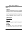
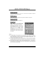
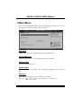
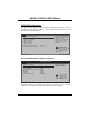
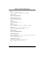
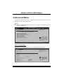
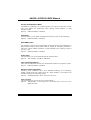
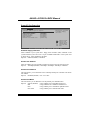
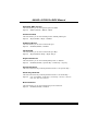
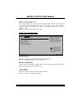
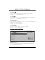
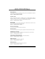
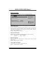
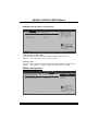
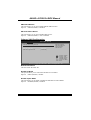
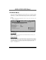
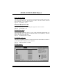
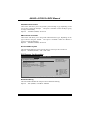
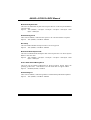
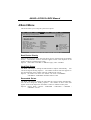
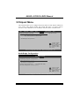
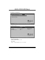
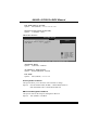
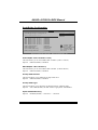
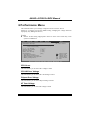
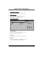
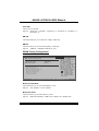
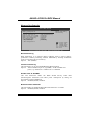
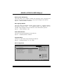
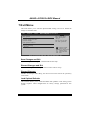
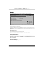
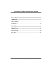
A880G+/A785G3+ BIOS Manual
BIOS Setup .................................................................................................1
1 Main Menu...............................................................................................3
2 Advanced Menu.......................................................................................6
3 PCIPnP Menu........................................................................................17
4 Boot Menu..............................................................................................21
5 Chipset Menu.........................................................................................24
6 Performance Menu...............................................................................30
7 Exit Menu...............................................................................................38
i
A880G+/A785G3+ BIOS Manual
BIOS Setup
Introduction
T he purpose of this manual is to describe the settings in the AMI BIOS Setup
program on this motherboard. The Setup program allows users to modify the basic
system configuration and save these settings to CMOS RAM. T he power of CMOS
RAM is supplied by a battery so that it retains the Setup information when the power
is turned off.
Basic Input-Output System (BIOS) determines what a computer can do without
accessing programs from a disk. T his system controls most of the input and output
devices such as keyboard, mouse, serial ports and disk drives. BIOS activates at the
first stag e o f the booting process, loading and executing the operating system. Some
additional features, such as virus and password prot ection or chipset fine-tuning
options are also included in BIOS.
T he rest of this manual will to guide you through the options and settings in BIOS
Setup.
Plug and Pla y Support
T his AMI BIOS supports the Plug and Play Version 1.0A specification.
EPA Green PC Support
T his AMI BIOS supports Version 1.03 of the EPA Green PC specification.
APM Support
T his AMI BIOS supports Version 1.1&1.2 of the Advanced Power Management
(APM) speci fication. Power management features are implemented via the System
Management Int errupt (SMI). Sleep and Suspend power man agement modes are
supported. Power to the hard disk drives and video monitors can also be managed by
this AMI BIOS.
ACPI Support
AMI ACPI BIOS support Version 1.0/2.0 of Advanced Configuration and Power
interface specifi cation (ACPI). It provides ASL code for pow er manag ement and
device con figuration capabilities as defined in the ACPI specification, developed by
Microso ft, Intel and T oshiba.
1
A880G+/A785G3+ BIOS Manual
PCI Bus Support
T his AMI BIOS also supports Version 2.3 of the Intel PCI (Peripheral Component
Interconn ect) local bus speci fication.
DRAM S upport
DDR3 SDRAM (Double Data Rate III Synchronous DRAM) is supported.
Supported CP Us
T his AMI BIOS supports the AMD CPU.
Using Setup
When starting up the computer, press
<Del> during the Power-On Self-Test
(POST) to enter the BIOS setup utility.
In the BIOS setup utility, you will see
General Help description at the top right
corner, and this is providing a brief
description of the selected item.
Navigation Keys for that particular menu
are at the bottom right corner, and you can
use these keys to select item and ch ange
the settings.
General Help
Navigation Keys
Notice
z
z
z
T he default BIOS settings apply for most conditions to ensure optimum performan ce
of the motherboard. If the system becomes unstable after changing any settings,
please load the default settings to ensure system’s compatibility and stability. Use
Load Setup Default under the Exit Menu.
For better system perform ance, the BIOS firmware is being continuously updated.
T he BIOS information described in this manual is for your reference only. The actual
BIOS information and settings on board may be slightly different from this manual.
T he content of this manual is subject to be chang ed without notice. We will not be
responsible for any mistakes found in this user’s manual and any system damage that
may be caused by wrong-settings.
2
A880G+/A785G3+ BIOS Manual
1 Main Menu
Once you enter AMI BIOS Setup Utility, the Main Menu will appear on the screen
providing an overview of the basic system inform ation.
Main
Advanced
PCIPnP
BIOS SETUP UTILITY
Boot
Chipset
Performance
System Overview
Exit
Use [ENTER], [TAB]
or [SHIFT-TAB] to
select a field.
AMI BIOS
Version
:01.01.01
Build Date:01/01/10
Use [+] or [-] to
configure system Time.
System Memory
Size
:
System Time
System Date
[00 :00:00]
[Fri 01/01/2010]
Floppy A
+Tab
F1
F10
ESC
> IDE/SATA Configuration
Select Screen
Select Item
Change Field
Select Field
General Help
Save and Exit
Exit
vxx.xx (C)Copyright 1985-200x, American Megatrends, Inc.
AMI BIOS
Shows system information including BIOS version and built date.
System Memory
Shows system memory size, VGA shard memory will be excluded..
System Time
Set the system internal clock.
System Date
Set the system date. Note that the ‘Day’ automatically changes when you set the
date.
Floppy A
Select the type of floppy disk drive installed in your system.
Options: 360K, 5.25 in / 1.2M, 5.25 in / 720K, 3.5 in / 1.44M, 3.5 in /
2.88M, 3.5 in / None
3
A880G+/A785G3+ BIOS Manual
IDE/S ATA Configuration
T he BIOS will automatically detect the presence of ID E/SAT A devices. There is a
sub-menu fo r each IDE/SAT A device. Select a device and press <Enter> to enter
the sub-menu of detailed options.
BIOS SETUP UTILITY
Main
IDE/SATA Configuration
>
>
>
>
>
>
While entering setup,
BIOS auto detects the
presence of IDE
devices. This displays
the status of auto
detection of IDE
devices.
Primary IDE Master
Primary IDE Slave
SATA 1 Device
SATA 2 Device
SATA 3 Device
SATA 4 Device
Hard Disk Write Protect
IDE Detect Time Out (Sec)
[Disabled]
[35]
Select Screen
Select Item
EnterGo to Sub Screen
F1
General Help
F10 Save and Exit
ESC Exit
vxx.xx (C)Copyright 1985-200x, American Megatrends, Inc.
Primary IDE Master/Slav e ; SATA 1/2/3/4 Device
BIOS SETUP UTILITY
Main
Select the type
of device connected
to the system.
Primary IDE Master
Device
:
Type
[Auto]
LBA/Large Mode
[Auto]
Block (Multi-Sector Transfer)[Auto]
PIO Mode
[Auto]
DMA Mode
[Auto]
S.M.A.R.T
[Auto]
32Bit Data Transfer
[Enabled]
+F1
F10
ESC
Select Screen
Select Item
Change Option
General Help
Save and Exit
Exit
vxx.xx (C)Copyright 1985-200x, American Megatrends, Inc.
T he BIOS detects the information and values of resp ective devices, and these
information and values are shown below to the name of the sub-menu.
4
A880G+/A785G3+ BIOS Manual
Type
Select the type of the IDE/SAT A drive.
Options: Auto (Default) / CDROM / ARMD / Not Installed
LBA/Large Mode
Enable or disable the LBA mode.
Options: Auto (Default) / Disabled
Block (Multi-Sector Transfer)
Enable or disable multi-sector trans fer.
Options: Auto (Default) / Disabled
PIO Mode
Select the PIO mode.
Options: Auto (Default) / 0 / 1 / 2 / 3 / 4
DMA Mode
Select the DMA mode.
Options: Auto (Default) / SWDMA0 ~ 2 / MWDMA0 ~ 2 / UDMA0 ~ 5
S.M.A.R.T
Set the Smart Monitoring, Analysis, and Reporting T echnology.
Options: Auto (Default) / Disabled / Enabled
32Bit Data Transfer
Enable or disable 32-bit data transfer.
Options: Enabled (Default) / Disabled
Hard Disk Write Protect
Disable or enable device write protection. T his will be effective only if the device
is accessed through BIOS.
Options: Disabled (Default) / Enabled
IDE Detect Time Out (Sec)
Select the time out value for detecting IDE/SAT A devices.
Options: 35 (Default) / 30 / 25 / 20 / 15 / 10 / 5 / 0
5
A880G+/A785G3+ BIOS Manual
2 Advanced Menu
T he Advanced Menu allows you to configu re the settings of CPU, Super I/O, Power
Management, and other system devices.
Notice
z
Beware of that setting inappropriate values in items of this menu may cause
system to malfunction.
Main
Advanced
PCIPnP
BIOS S ETUP UTILITY
Boot
Chips et
Perfo rmance
Advan ced Settings
Exit
Conf igure CPU.
WARNI NG: Setting w rong values in below sec tions
may cause system to m alfunction.
>
>
>
>
>
>
>
>
CPU Configuratio n
Sup erIO Configur ation
Sma rt Fan Config uration
Har dware Health Configuratio n
Pow er Configurat ion
USB Configuratio n
AUD IO Configurat ion
Onb oard LAN Conf iguration
S elect Screen
S elect Item
En terG o to Sub Scr een
F1
G eneral Help
F1 0 S ave and Exit
ES C E xit
vxx.xx (C)C opyright 198 5-200x, Amer ican Megatre nds, Inc.
CPU Configuration
T his item shows the CPU information that the BIOS automatically detects.
BIOS SETUP UTILITY
Advanced
CPU Configuration
Module Version:
AGESA Version:
Physical Count:
Logical Count:
Enable/Disable
Secure Virtual Machine
Mode (SVM)
AMD CPU
Revision:
Cache L1:
Cache L2:
Cache L3:
Speed
:
NB Clk:
ncHT Speed :
WidthI/O :
Able to Change Freq
:
uCode Patch Level
:
Secure Virtual Machine Mode [Enabled]
PowerNow
[Enabled]
ACPI SRAT Table
[Enabled]
Probe Filter
[Enabled]
+F1
F10
ESC
Select Screen
Select Item
Change Option
General Help
Save and Exit
Exit
vxx.xx (C)Copyright 1985-200x, American Megatrends, Inc.
6
A880G+/A785G3+ BIOS Manual
Secure Virtual Machine Mode
Virtualization T echnology can virtually separate your system resou rce into several
parts, thus enhance the performance when running virtual machines or multi
interface systems.
Options: Enabled (Default) / Disabled
PowerNow
T his item allows you to enable or disable the PowerNow power saving technology.
Options: Enabled (Default) / Disabled
ACPI SRAT Table
T he operating system scans the ACPI SRAT at boot time and uses the information to
better allocate memory and schedule software threads for maximum perform ance.
T his item controls whether the SRAT is made available to the operating system at
boot up, or not.
Options: Enabled (Default) / Disabled
Probe Filter
T his item allows you to set initialization mode for Probe Filter.
Options: Auto (Default) / Disabled / MP Mode
Core Performance Boost
If this item is enabled, Revision E CPU automatically transition to pop-down p-state
Options: Enabled (Default) / Disabled
Advanced Clock Calibration
Advanced Clock Calibration (ACC) is an enhanced technology fo r overclocking,
needing support from both chipset and CPU. When enabled, it will improve the
stability of advanced overclocking greatly.
Options: Disabled (Default) / Auto / All Cores / Per Core
Core Leveling
T his item allows you to activate Core Leveling function.
Options: Auto(Default) / Force Single Core / Force Dual Core / Force Tri Core /
Enable all Cores
7
A880G+/A785G3+ BIOS Manual
SuperIO Configuration
Advanced
BIOS SETUP UTILITY
Configure ITE8721 Super IO Chipset
Onboard Floppy Controller
Serial Port1 Address
Parallel Port Address
OnBoard CIR Port
Keyboard PowerOn
Mouse PowerOn
Restore on AC Power Loss
[Enabled]
[3F8/IRQ4]
[Disabled]
[Disabled]
[Disabled]
[Disabled]
[Power Off]
Allows BIOS to Enable
or Disable Floppy
Controller
+F1
F10
ESC
Select Screen
Select Item
Change Option
General Help
Save and Exit
Exit
vxx.xx (C)Copyright 1985-200x, American Megatrends, Inc.
Onboard Floppy Controller
Select enabled if your system has a floppy disk controller (FDC) installed on the
system board and you wish to use it. If you installed another FDC or the system uses
no floppy drive, select disabled in this field.
Options: Enabled (Default) / Disabled
Serial Port1 Address
Select an address and corresponding interrupt fo r the first and second seri al ports.
Options: 3F8/IRQ4 (Default) / 2F8/IRQ3 / 3E8/IRQ4 / 2E8/IRQ3 / Disabled
Parallel Port Address
T his item allows you to determine access onboard p arallel port controller with which
I/O Address.
Options: Disabled (Default) / 378 / 278 / 3BC
Parallel Port Mode
T his item allows you to determine how the parallel port should function.
Options: Normal (Default) Using Parallel port as Standard Printer Port.
EPP
Using Parallel Port as Enhanced Parallel Port.
ECP
Using Parallel port as Extended Capabilities Port.
ECP+EPP
Using Parallel port as ECP & EPP mode.
8
A880G+/A785G3+ BIOS Manual
ECP Mode DMA Channel
T his item allows you to select parallel port ECP DMA.
Options: DMA3 (Default) / DMA0 / DMA1
Parallel Port IRQ
T his item allows you to select the IRQ for the onboard parallel port.
Options: IRQ7 (Default) / IRQ5 / Disabled
OnBoard CIR Port
T his item allows you to select consumer IR port.
Options: Disabled (Default) / Enabled
CIR Port IRQ
T his item allows you to select consumer IR port IRQ.
Options: IRQ10 (Default) /IRQ3 / IRQ4 / IRQ11
Keyboard Pow erOn
T his item allows you to control the keyboard power on function.
Options: Disabled (Default) / Specific Key / Stroke Key / Any Key
Specific Key Enter
T his item will show only when Keyboard PowerOn is set “Specific Key.”
Stroke Keys Selected
T his item will show only when Keyboard PowerOn is set “Stroke Key.”
Options: Ctrl+F1 (Default) / Wake Key / Power Key / Ctrl+F2 / Ctrl+F3 /
Ctrl +F4 / Ctrl+F5 / Ctrl+F6
Mouse PowerOn
T his item allows you to control the mouse power on function.
Options: Disabled (Default) / Enabled
9
A880G+/A785G3+ BIOS Manual
Restore on AC Power Loss
T his setting specifies how your system should behave after a power fail or interrupts
occurs. By choosing Disabled will leave the computer in the power off state.
Choosing Enabled will restore the system to the status before power failure or
interrupt occurs.
Options: Power O ff (Default) / Last State
Smart Fan Configuration
BIOS SETU P U TILITY
Advan ced
Smart Fan Conf iguration
CPU Smart Fan
Smart Fan Cali bration
Control Mode
Fan Ctrl OFF(o C)
Fan Ctrl On(oC )
Fan Ctrl Start value
Fan Ctrl Sensi tive
[Dis abled]
When you choice [Auto]
,[3Pin] or [4Pin],
please run the
calibration to define
the Fan parameters for
Smart Fan control
+F1
F10
ESC
S elect Screen
S elect Item
C hange Option
G eneral Help
S ave and Exit
E xit
vxx .xx (C)Copyright 1985-200x, American Me gatrends, Inc.
CPU Smart Fan
T his item allows you to control the CPU Smart Fan function.
Options: Disabled (Default) / Auto / 4Pin / 3Pin
Smart Fan Calibration
Choose this item and then the BIOS will auto test and detect the CPU/System fan
fun ctions and show CPU/System fan speed.
Control Mode
T his item provides several operation modes of the fan.
Options: Quiet / Performan ce / Manual
10
A880G+/A785G3+ BIOS Manual
Fan Ctrl OFF(℃ )
If the CPU/System T emperature is lower than the set value, FAN will turn off.
Options: 0~127 (℃) (With the interval of 1℃)
Fan Ctrl On(℃ )
CPU/System fan starts to work under smart fan function when arrive this set value.
Options: 0~127 (℃) (With the interval of 1℃)
Fan Ctrl Start Value
When CPU/System temperature arriv es to the set value, the CPU/System fan will
work under Smart Fan Function mode.
Options: 0~127 (With the interval of 1)
Fan Ctrl Sensitive
Increasing the value will raise the speed of CPU/System fan.
Options: 1~127 (With the interval of 1)
Hardware Health Configuration
T his item shows the system temperature, fan speed, and voltage information.
Advanced
BIOS SETUP UTILITY
Hardware Health Configuration
H/W Health Function
Shutdown Temperature
[Enabled]
[Disabled]
Enables Hardware
Health Monitoring
Device.
CPU Temperature
NB Temperature
SYS Temperature
CPU Fan
Sytem1 Fan
+12.0V
Chip Voltage
+5.00V
CPU Vcore
DDR Voltage
HT Voltage
+F1
F10
ESC
Select Screen
Select Item
Change Option
General Help
Save and Exit
Exit
vxx.xx (C)Copyright 1985-200x, American Megatrends, Inc.
H/W Health Function
If with a monitoring system, the system will show PC health status duringPOST stage.
Options: Enabled (Default) / Disabled
11
A880G+/A785G3+ BIOS Manual
Shutdow n Temperature
T his item allows you to set up the CPU shutdown T emperature. This item is only
effective under Windows 98 ACPI mode.
Options: Disabled (Default) / 60℃/140℉ / 65℃/149℉ / 70℃/158℉ / 75℃/167℉
/ 80℃/176℉ / 85℃/185℉ / 90℃/194℉
Power Configuration
BIOS S ETUP UTILITY
Advanced
ACPI Settings
Suspe nd mode
ACPI Version Featu res
ACPI APIC support
AMI O EMB table
Headl ess mode
[ S1 (POS)]
[ ACPI v1.0]
[ Enabled]
[ Enabled]
[ Disabled]
RTC R esume
[ Disabled]
RTC A larm Date(Day s)
RTC A larm T ime
USB W akeup From S3 /S4
[ Disabled]
Power ON by PCIE/O nboard LAN [ Disabled]
Wake Up by PCI
[ Disabled]
Wakeu p on Ring
[ Disabled]
Sele ct the ACPI
stat e used for
Syst em Suspend.
+F1
F1 0
ES C
S elect Screen
S elect Item
C hange Option
G eneral Help
S ave and Exit
E xit
vxx.xx (C)C opyright 198 5-200x, Amer ican Megatre nds, Inc.
Suspend mode
T he item allows you to select the suspend type under the ACPI operating system.
Options: S1 (POS) (Default)
Power on Suspend
S3 (ST R)
Suspend to RAM
S1 & S3
POS+STR
ACPI Version Features
T he item allows you to select the version of ACPI.
Options: ACPI v1.0 (Default) / ACPI v2.0 / ACPI v3.0
ACPI APIC support
T his item is used to enable or disable the motherboard's APIC (Advan ced
Programmable Interrupt Controller). T he APIC provides multiprocessor support,
more IRQs and faster interrupt handling.
Options: Enabled (Default) / Disabled
12
A880G+/A785G3+ BIOS Manual
AMI OEMB table
Set this value to allow the ACPI BIOS to add a pointer to an OEMB table in the Root
System Description T able (RSDT ) table.
Options: Enabled (Default) / Disabled
Headless mode
T his is a server-speci fic feature. A headless server is one that operates without a
keyboard, monitor or mouse. To run in headless mode, both BIOS and operating
system (e.g. Windows Server 2003) must support headless operation.
Options: Disabled (Default) / Enabled
RTC Resume
When “ Enabled”, you can set the date and time at which the RT C (real-time clock)
alarm awak ens the system from Suspend mode.
Options: Disabled (Default) / Enabled
RTC Alarm Date (Days)
You can choose which date the system will boot up.
RTC Alarm Time
You can choose the system boot up time, input hour, minute and second to specify.
USB Wakeup from S3/S4
T his item allows you to enable or disabled the USB resume from S3/S4 function.
Options: Disabled (Default) / Enabled
Power On by PCIE/Onboard LAN
T his item allows you control the wake on LAN (WOL) function.
Options: Disabled (Default) / Enabled
Wake Up by PCI
Enable / Disable PCI to generate a wake ev ent.
Options: Disabled (Default) / Enabled
Wakeup on Ring
T his item allows you control the wake on ring function.
Options: Disabled (Default) / Enabled
13
A880G+/A785G3+ BIOS Manual
USB Configuration
T his item shows the USB controller and using USB device information.
Advanced
BIOS SETUP UTILITY
USB Configuration
Enables support for
legacy USB. AUTO
option disables
legacy support if
no USB devices are
connected.
Module Version - 2.24.5-13.4
USB Devices Enabled:
Legacy USB Support
USB 2.0 Controller Mode
BIOS EHCI Hand-Off
Legacy USB1.1 HC Support
[Enabled]
[HiSpeed]
[Enabled]
[Enabled]
> USB Mass Storage Device Configuration
+F1
F10
ESC
Select Screen
Select Item
Change Option
General Help
Save and Exit
Exit
vxx.xx (C)Copyright 1985-200x, American Megatrends, Inc.
Legacy USB Support
T his item determines if the BIOS should provide legacy support fo r USB devices
like the keyboard, mouse, and USB drive. T his is a useful feature when using such
USB devices with operating systems that do not natively support USB (e.g.
Microso ft DOS or Windows NT).
Options: Enabled (Default) / Disabled
USB 2.0 Controller Mode
T his item allows you to select the operation mode of the USB 2.0 controller.
Options: HiSpeed (Default) USB 2.0-480Mbps
FullSpeed
USB 1.1-12Mbps
BIOS EHCI Hand-Off
T his item allows you to enable support for op erating systems without an EHCI
hand-o ff feature.
Options: Enabled (Default) / Disabled
Legacy USB1.1 HC Support
T his item allows you to enable to support USB1.1 HC.
Options: Enabled (Default) / Disabled
14
A880G+/A785G3+ BIOS Manual
USB Mass Storage Dev ice Configuration
BIOS SETUP UTILITY
Advanced
USB Mass Storage Device Configuration
USB Mass Storage Reset Delay [20 Sec]
Device #
Emulation Type
Number of seconds
POST waits for the
USB mass storage
device after start
unit command.
[Auto]
+F1
F10
ESC
Select Screen
Select Item
Change Option
General Help
Save and Exit
Exit
vxx.xx (C)Copyright 1985-200x, American Megatrends, Inc.
USB Mass Storage Reset Delay
T his item allows you to set the reset delay for USB mass storage device.
Options: 20 Sec (Default) / 10 Sec / 30 Sec / 40 Sec
Emulation Type
T his item allows you to select the emulation type of the USB mass storage device.
Options: Auto (Default) / Floppy / Forced FDD / Hard Disk / CDROM
AUDIO Configuration
BIOS SETUP UTILITY
Chipset
AUDIO Configuration
AMD 880 HD Audio
HD Audio Azalia Device
Options
[Enabled]
[Enabled]
Disabled
Enabled
Select Screen
Select Item
EnterUpdate
F1
General Help
F10 Save and Exit
ESC Exit
vxx.xx (C)Copyright 1985-200x, American Megatrends, Inc.
15
A880G+/A785G3+ BIOS Manual
AMD 880 HD Audio
T his item allows you to control AMD 880 HD audio function.
Options: Enabled (Default) / Disabled
HD Audio Azalia Device
T his item allows you to control the HD audio device.
Options: Enabled (Default) / Auto / Disabled
Onboard LAN Configuration
BIOS S ETUP UTILITY
Advanced
Onboa rd LAN Config uration
Enab le/Disable
Onbo ard Realtek
PCIE Network
Cont roller
MAC I D Information :
Realt ek PCIE NIC
Real tek Option RO M
[ Enabled]
[ Disabled]
+F1
F1 0
ES C
S elect Screen
S elect Item
C hange Option
G eneral Help
S ave and Exit
E xit
vxx.xx (C)C opyright 198 5-200x, Amer ican Megatre nds, Inc.
MAC ID Information
T his area shows the MAC ID.
Realtek PCIE NIC
T his option allows you to control the onboard LAN controller.
Options: Enable (Default) / Disable
Realtek Option ROM
T his item allows you to enable or disable the Onboard LAN Boot ROM.
Options: Disabled (Default) / Enabled
16
A880G+/A785G3+ BIOS Manual
3 PCIPnP Menu
T his section describes con figuring the PCI bus system. PCI, or Personal Computer
Interconn ect, is a system which allows I/O devices to operate at speeds nearing the
speed o f the CPU itself uses when communicating with its own special components.
Notice
z
Beware of that setting inappropriate values in items of this menu may cause
system to malfunction.
Main
Advan ced
PCIPnP
BIOS SETU P U TILITY
Boot
Chipset
Performance
Advanced PCI/P nP Settings
Exit
Clear NVRAM during
System Boot.
WARNING: Setti ng wrong values in below sections
may c ause system to malf unction.
Clear NVRAM
Plug & Play O/ S
PCI Latency Ti mer
Allocate IRQ t o PCI VGA
Palette Snoopi ng
PCI IDE BusMas ter
[No]
[No]
[64]
[Yes ]
[Dis abled]
[Ena bled]
> PCI Resource
> PCI Express Configuration
+F1
F10
ESC
S elect Screen
S elect Item
C hange Option
G eneral Help
S ave and Exit
E xit
vxx .xx (C)Copyright 1985-200x, American Me gatrends, Inc.
Clear NV RAM
T his item allows you to clear the data in the NVRAM (CMOS) by selecting “Yes”.
Options: No (Default) / Yes
Plug & P lay OS
When set to YES, BIOS will only initialize the PnP cards used for the boot sequen ce
(VGA, IDE, SCSI). The rest of the cards will be initialized by the PnP operating
system like Window™ 95. When set to NO, BIOS will initialize all the PnP cards.
For non-PnP operating systems (DOS, Netware™), this option must set to NO.
Options: No (Default) / Yes
17
A880G+/A785G3+ BIOS Manual
PCI Latency Timer
T his item controls how long a PCI device can hold the PCI bus before another takes
over. T he longer the latency, the longer the PCI device can retain control of the bus
before handing it over to another PCI device.
Options: 64 (Default) / 0-255
Allocate IRQ to PCI V GA
T his item allows BIOS to choose a IRQ to assign for the PCI VGA card.
Options: Yes (Default) / No
Palette Snooping
Some old graphic controllers need to “ snoop” on the VGA palette and then map it to
their display as a way to provide boot information and VGA compatibility. This item
allows such snooping to take place.
Options: Disabled (Default) / Enabled
PCI IDE BusMaster
T his item is a toggle for the built-in driver that allows the onbo ard ID E controller to
perform DMA (Direct Memory Access) trans fers.
Options: Enabled (Default) / Disabled
PCI Resource
BIOS SETUP UTILITY
PCIPnP
PCI Resource
IRQ3
IRQ4
IRQ5
IRQ7
IRQ9
IRQ10
IRQ11
IRQ14
IRQ15
DMA
DMA
DMA
DMA
DMA
DMA
[Available]
[Available]
[Available]
[Available]
[Available]
[Available]
[Available]
[Available]
[Available]
Channel
Channel
Channel
Channel
Channel
Channel
0
1
3
5
6
7
Reserved Memory Size
[Available]
[Available]
[Available]
[Available]
[Available]
[Available]
Available: Specified
IRQ is available to be
used by PCI/PnP
devices.
Reserved: Specified
IRQ is reserved for
use by Legacy ISA
devices.
+F1
F10
ESC
Select Screen
Select Item
Change Option
General Help
Save and Exit
Exit
[Disabled]
vxx.xx (C)Copyright 1985-200x, American Megatrends, Inc.
18
A880G+/A785G3+ BIOS Manual
IRQ3/4/5/7/9/10/11/14/15
T hese items will allow you to assign each system interrupt a type, depending on the
type of device using the interrupt. T he option “Available” means the IRQ is going
to assign automatically.
Options: Available (Default) / Reserved
DMA Channel 0/1/3/5/6/7
T hese items will allow you to assign each DMA channel a type, depending on the
type of device using the channel. T he option “ Available” means the channel is
going to assign automatically.
Options: Available (Default) / Reserved
Reserved Memory Size
T his item allows BIOS to reserve cert ain memory size for speci fic PCI device.
Options: Disabled (Default) / 16K / 32K / 64K
PCI Express Configuration
PCIPnP
BIOS SETUP UTILITY
PCI Express Configuration
Relaxed Ordering
[Auto]
Maximum Payload Size
[Auto]
Extended Tag Field
[Auto]
No Snoop
[Auto]
Maximum Read Request Size
[Auto]
Active State Power-Management[Disabled]
Extended Synch
[Auto]
Enable/Disable
Pci Express Device
Relaxed Ordering.
+F1
F10
ESC
Select Screen
Select Item
Change Option
General Help
Save and Exit
Exit
vxx.xx (C)Copyright 1985-200x, American Megatrends, Inc.
Relaxed Ordering
T his item enables/disables PCI Express Device Relaxed Ordering.
Options: Auto (Default) / Disabled / Enabled
19
A880G+/A785G3+ BIOS Manual
Maximum Payload Size
T his item sets Maximum Payload of Pci Express Device or allows System BIOS to
select the value.
Options: Auto (Default) / 128 Bytes / 256 Bytes / 512 Bytes / 1024 Bytes / 2048
Bytes / 4096 Bytes
Extended Tag Field
If this item is enabled, it will allow the system to use 8-bit TAG filed as a requester.
Options: Auto (Default) / Disabled / Enabled
No Snoop
T his item enables/disables Pci Express Device No Snoop option.
Options: Auto (Default) / Disabled / Enabled
Maximum Read Request Size
T his item sets Maximum Read Request Size of Pci Express Devi ce or allows System
BIOS to select the value.
Options: Auto (Default) / 128 Bytes / 256 Bytes / 512 Bytes / 1024 Bytes / 2048
Bytes / 4096 Bytes
Active State Power-Management
T his item sets the ASPM configuration for the PCI Express devices b efore the
operating system boots. T his function is for OS which does not support ASPM.
Options: Disabled (Default) / Enabled
Extended Synch
If this item is enabled, it will allow generation o f Extended Synchronization patterns.
Options: Auto (Default) / Disabled / Enabled
20
A880G+/A785G3+ BIOS Manual
4 Boot Menu
T his menu allows you to setup the system boot options.
Main
Advanced
PCIPnP
BIOS SETUP UTILITY
Boot
Chipset
Performance
Boot Settings Configuration
>
>
>
>
Exit
Specifies the
Boot Device
Priority sequence.
Boot Device Priority
Hard Disk Drives
Removable Drives
CD/DVD Drives
Quick Boot
Full Screen LOGO Show
AddOn ROM Display Mode
Bootup Num-Lock
Interrupt 19 Capture
Ignore Memory Error Messages
Smart Multi-Core
BOOT SUCCESS BEEP
[Enabled]
[Enabled]
[Force BIOS]
[ON]
[Disabled]
[Disabled]
[Auto]
[Enabled]
Select Screen
Select Item
EnterGo to Sub Screen
F1
General Help
F10 Save and Exit
ESC Exit
vxx.xx (C)Copyright 1985-200x, American Megatrends, Inc.
Boot De vice Priority
Items in this sub-menu specify the boot device priority sequence from the available
devices. T he number of device items that appears on the screen depends on the
number of devi ces installed in the system.
Options: Removable / Hard Disk / CDROM / Legacy LAN / Disabled
Hard Disk Drives
T he BIOS will attempt to arrange the hard disk boot sequence automatically. You
can also ch ange the booting sequence. T he number of device items that appears on
the screen depends on the number of devices installed in the system.
Options: Pri. Master / Pri. Slave / Sec. Master / Sec. Slave / USB HDD0 /
USB HDD1 / USB HDD2 / Bootable Add-in Cards
Removable Drives
T he BIOS will attempt to arrange the removable drive boot sequence automatically.
You can also change the booting sequence. The number of device items that
appears on the screen depends on the number of devices installed in the system.
Options: Floppy Disks / Zip100 / USB-FDD0 / USB-FDD1 / USB-ZIP0 /
USB-ZIP1 / LS120
21
A880G+/A785G3+ BIOS Manual
CD/DV D Drives
T he BIOS will attempt to arrange the CD/DVD drive boot sequence automatically.
You can also change the booting sequence. The number of device items that
appears on the screen depends on the number of devices installed in the system.
Options: Pri. Master / Pri. Slave / Sec. Master / Sec. Slave / USB CDROM0 /
USB CDROM 1
Quick Boot
Enabling this option will cause an ab ridged version o f the Power On Sel f-T est
(POST ) to execute after you power up the computer.
Options: Enabled (Default) / Disabled
Full Screen LOGO Show
T his item allows you to enable/disable Full Screen LOGO Show function.
Options: Enabled (Default) / Disabled
AddOn ROM Display Mode
T his item sets the display mode for option ROM.
Options: Force BIOS (Default) / Keep Current
Bootup Num-Lock
Selects the NumLock State after the system switched on.
Options: ON (Default) / OFF
Interrupt 19 Capture
When set to Enabled, this item allows the option ROMs to trap interrupt 19.
Options: Disabled (Default) / Enabled
Ignore Memory Error Messages
When set to Enabled, the POST will ignore memory error messages.
Options: Disabled (Default) / Enabled
Smart Multi-Core
Options:
Auto (Default) / Disabled
22
A880G+/A785G3+ BIOS Manual
BOOT S UCCESS BEEP
When this item is set to Enabled, BIOS will let user know boot success with beep.
Options: Enabled (Default) / Disabled
23
A880G+/A785G3+ BIOS Manual
5 Chipset Menu
T his submenu allows you to configure the speci fic features of the chipset installed on
your system. T his chipset manage bus speeds and access to system memory
resources, such as DRAM. It also coordinates communications with the PCI bus.
Main
Advanced
PCIPnP
BIOS S ETUP UTILITY
Boot
Chips et
Perfo rmance
Advan ced Chipset S ettings
Exit
Opti ons for NB
WARNI NG: Setting w rong values in below sec tions
ma y cause syst em to malfun ction.
> Nor thBridge Conf iguration
> Sou thBridge Conf iguration
S elect Screen
S elect Item
En terG o to Sub Scr een
F1
G eneral Help
F1 0 S ave and Exit
ES C E xit
vxx.xx (C)C opyright 198 5-200x, Amer ican Megatre nds, Inc.
NorthBridge Configuration
BIOS SETUP UTILITY
Chipset
NorthBridge Chipset Configuration
RS880 CIMx Version : 5.9.1
> Internal Graphics Configuration
> PCI Express Configuration
Primary Video Controller
[PCI-GFX0-GPP-IGFX]
NB Power Management Features [Auto]
Select Screen
Select Item
EnterGo to Sub Screen
F1
General Help
F10 Save and Exit
ESC Exit
vxx.xx (C)Copyright 1985-200x, American Megatrends, Inc.
24
A880G+/A785G3+ BIOS Manual
Internal Graphics Configuration
BIOS S ETUP UTILITY
Chips et
Inter nal Graphics Configuratio n
Options
Inter nal Graphics Mode
UMA Frame Buffer Size
GFX E ngine Clock O verride
[ UMA]
[ Auto]
[ Disable]
Surro und View
FB Lo cation
[ Disabled]
[ Above 4G]
Disa ble
UMA
S elect Screen
S elect Item
C hange Option
+F1
G eneral Help
F1 0 S ave and Exit
ES C E xit
vxx.xx (C)C opyright 198 5-200x, Amer ican Megatre nds, Inc.
Internal Graphics Mode
T his item allows you to select the memory mode used for internal graphi cs device.
Options: UMA (Default) / Disable
UMA Frame Buffer Size
T his item allows you to choose the UMA frame buffer size for internal graphics.
Options: Auto (Default) / 32MB / 64MB / 128MB / 256MB / 512MB
GFX Engine Clock Override
T his item allows you to control the internal GFX engine clock override function.
Options: Disabled (Default) / Enabled
GFX Engine Clock
T his item allows you to set the internal GFX engine clock.
Options: 500 (Default) / Min: 150, Max: 1200
Surround View
T his item allows you to control the Surround View Function.
Options: Disabled / Enabled / Auto (Default)
FB Location
T his item allows you to set the FB-DIMM location.
Options: Above 4G (Default) / Under 4G
25
A880G+/A785G3+ BIOS Manual
PCI Express Configuration
BIOS SETUP UTILITY
Chipset
PCI Express Configuration
> Port #02 Features
> Port #07 Features
> NB-SB Port Features
Select Screen
Select Item
EnterUpdate
F1
General Help
F10 Save and Exit
ESC Exit
vxx.xx (C)Copyright 1985-200x, American Megatrends, Inc.
Port #02/07 Features
BIOS SETU P U TILITY
Chipset
Gen2
Link
Link
Slot
High Spee d Mode
ASPM
Width
Power Lim it,W
[Dis abled]
[Dis abled]
[Aut o]
[75 ]
Auto - RC only
advertize Gen2
capability.
+F1
F10
ESC
S elect Screen
S elect Item
C hange Option
G eneral Help
S ave and Exit
E xit
vxx .xx (C)Copyright 1985-200x, American Me gatrends, Inc.
Gen2 High Speed Mode
Options: Disabled (Default) / Auto
Link ASPM
Options: Disabled (Default) / L0s / L1 / L0x & L1
26
A880G+/A785G3+ BIOS Manual
Link Width (Only for Port #02)
Options: Auto (Default) / x1 / x2 / x4 / x8 / x16
Slot Power Limit, W (Only for Port #02)
Options: 75 (Default) / 0-255
NB-SB Port Features
BIOS S ETUP UTILITY
Chips et
NB-SB Link ASPM
[ L1]
NP NB -SB VC1 Traff ic Support [ Disabled]
Link Width
[ Auto]
Options
Disa bled
L1
S elect Screen
S elect Item
C hange Option
+F1
G eneral Help
F1 0 S ave and Exit
ES C E xit
vxx.xx (C)C opyright 198 5-200x, Amer ican Megatre nds, Inc.
NB-SB Link ASPM
Options: L1(Default) / Disabled
NP NB-SB VC1 Traffic Support
Options: Disabled (Default) / Enabled
Link Width
Options: Auto (Default) / x1 / x2 / x4
Primary Video Controller
T his option allows you to select the video controller in charge.
Options: PCI-GFX0-GPP-IGFX (Default) / GFX0-GPP-IGFX-PCI /
GPP-GFX0-IGFX-PCI / IGFX-GFX0-GPP-PCI
NB Power Management Features
T his option controls the NB power management function.
Options: Auto (Default) / Disabled
27
A880G+/A785G3+ BIOS Manual
SouthBridge Configuration
BIOS S ETUP UTILITY
Chips et
South Bridge Chipse t Configurat ion
Options
SB710 CIMx Verison : 4.7.0
OHCI
OHCI
EHCI
OHCI
OHCI
EHCI
OHCI
HC(Bus
HC(Bus
HC(Bus
HC(Bus
HC(Bus
HC(Bus
HC(Bus
0
0
0
0
0
0
0
Dev
Dev
Dev
Dev
Dev
Dev
Dev
18
18
18
19
19
19
20
Fn
Fn
Fn
Fn
Fn
Fn
Fn
o)
1)
2)
0)
1)
2)
5)
Disa bled
Enab led
[ Enabled]
[ Enabled]
[ Enabled]
[ Enabled]
[ Enabled]
[ Enabled]
[ Enabled]
OnChi p SATA Channe l
OnChi p SATA Type
Optio n ROM POST De lay
[ Enabled]
[ Native IDE]
[ Disabled]
Power Saving Featu res
[ Disabled]
S elect Screen
S elect Item
En terG o to Sub Scr een
F1
G eneral Help
F1 0 S ave and Exit
ES C E xit
vxx.xx (C)C opyright 198 5-200x, Amer ican Megatre nds, Inc.
OHCI HC(Bus 0 Dev 18/19/20 Fn 0/1/5)
T his item allows you to control OHCI host controller. (USB 1.1 Device)
Options: Enabled (Default) / Disabled
EHCI HC(Bus 0 Dev 18/19 Fn 2)
T his item allows you to control EHCI host controller. (USB 2.0 Device)
Options: Enabled (Default) / Disabled
OnChip SATA Channel
T his option allows you to enable the on-chip Serial AT A.
Options: Enabled (Default) / Disabled
OnChip SATA Type
T his option allows you to select the on-chip Serial AT A operation mode.
Options: Native IDE (Default) / RAID / AHCI / Legacy IDE / IDEÆAHCI
Option ROM POST Delay
Options:
Disabled (Default) / 1 Second / 2 ~ 7 Seconds
28
A880G+/A785G3+ BIOS Manual
SATA IDE Combined Mode
T his option controls the SAT A/PAT A combined mode.
Options: Enabled (Default) / Disabled
Power Saving Features
T his item allows you to enable or disable power saving features in SB. As general
rule, this feature should be disabled for desktop and enabled fo r mobile. See AMD
SB710 Power Saving document for more details.
Options: Disabled (Default) / Enabled
29
A880G+/A785G3+ BIOS Manual
6 Performance Menu
T his submenu allows you to change voltage and clock of various devices.
(Howev er, we suggest you use the default setting. Changing the voltage and clock
improperly may damage the device.)
Notice
z
Beware of that setting inappropriate values in items of this menu may cause
system to malfunction.
Main
Advanced
PCIPnP
BIOS SETUP UTILITY
Boot
Chipset
Performance
Performance Settings
Exit
CPU Vcore Control
Notice: Please Clear CMOS if system no display
after overclocking
CPU Vcore
CPU NB Over Voltage
Chipset Over Voltage
HT Over Voltage
Memory Over Voltage
[StartUp]
[StartUp]
[1.23V]
[1.22V]
[1.60V]
CPU Frequency
[200]
> CPU FID/VID Control
> DRAM Timing Configuration
> Hyper Transport Configuration
> Memory Configuration
+F1
F10
ESC
Select Screen
Select Item
Change Option
General Help
Save and Exit
Exit
vxx.xx (C)Copyright 1985-200x, American Megatrends, Inc.
CPU Vcore
T his item allows you to select CPU Voltage Control.
CPU NB Over Voltage
T his item allows you to select CPU NB Voltage Control.
Chipset Over Voltage
T his item allows you to select Chipset Voltage Control.
HT Over Voltage
T his item allows you to select HT Voltage Control.
30
A880G+/A785G3+ BIOS Manual
Memory Over Voltage
T his item allows you to select DDR Voltage Control.
CPU Frequency
T his item allows you to select the CPU Frequency.
Options: 200 (MHz) (Default) / 200-600
CPU FID/VID Control
BIOS SETUP UTILITY
Performance
CPU FID/VID Control
Custom P-States
Core VID
Core FID
Core DID
NB VID
NB FID
[Disabled]
[1.2250 V]
[x14.0 2800MHz]
[Divided by 1]
[1.1500 V]
[2000 MHZ]
Tells BIOS whether to
use the setup options
below this to
configure the
P-States, or whether
to configure the
P-States automatically
+F1
F10
ESC
Select Screen
Select Item
Change Option
General Help
Save and Exit
Exit
vxx.xx (C)Copyright 1985-200x, American Megatrends, Inc.
Custom P-States
T his item allows you to select the P-States controlling.
Options: Disabled (Default) / Enabled
Core VID
T his function allows you to adjust the voltage of CPU.
Core FID
T his item allows you to select the Ratio/Frequency of CPU.
Options: x8.0 1600MHz ~ x16.5 3300MHz
31
A880G+/A785G3+ BIOS Manual
Core DID
T his is the Core Divider.
Options: Divided by 1 (Default) / Divided by 2 / Divided by 4 / Divided by 8 /
Divided by 16
NB VID
T his function allows you to adjust the voltage of NB chip.
NB FID
T his item allows you to select the Frequency o f NB chip.
Options: 800MHz ~ 2000MHz (Di ffered by CPU)
DRAM Timing Configuration
BIOS S ETUP UTILITY
Perfo rmance
DRAM Timing Config uration
Memor y Clock Mode
Mem clock Value
DRAM Timing Mode
[ Auto]
[ DDR3-800]
[ Auto]
Mem ory CLK
:
CAS Latency(Tcl)
:
RAS /CAS Delay(Tr cd)
:
Row Precharge Ti me(Trp):
Min Active RAS(T ras)
:
RAS /RAS Delay(Tr rd)
:
Row Cycle (Trc)
:
Com mand Rate(CR)
:
Sele ct the DRAM
Freq uency progra mming
meth od. If Auto,
the DRAM speed w ill
be b ased on SPDs .
If L imit, the DR AM spe
will not exceed the
spec ified value. If
Manu al, the DRAM speed
spec ified will b e
prog rammed regar dless.
S elect Screen
S elect Item
+C hange Option
F1
G eneral Help
F1 0 S ave and Exit
ES C E xit
vxx.xx (C)C opyright 198 5-200x, Amer ican Megatre nds, Inc.
Memory Clock Mode
T his item allows you to control the Memory Clock.
Options: Auto (Default) / Limit / Manual
Memclock Value
T his item allows you to set the Memory Clock.
Options: DDR3-800 (Default) / DDR3-1066 / DDR3-1333 / DDR3-1600
32
A880G+/A785G3+ BIOS Manual
DRAM Timing Mode
T his item allows you to choose to manually or automatically regul ate the DRAM
T iming.
Options: Auto (Default) / DCT0 / DCT 1 / Both
CAS Latency (CL)
Options: Auto (Default) / 4~12 CLK
2T Command
Options: Auto (Default) / 1T / 2T
TR CD
Options:
Auto (Default) / 5~12 CLK
TRP
Options:
Auto (Default) / 5~12 CLK
tR TP
Options:
Auto (Default) / 4~7 CLK
TR AS
Options:
Auto (Default) / 15~30 CLK
TR C
Options:
Auto (Default) / 11~42 CLK
tWR
Options:
Auto (Default) / 5~8 / 10 / 12 CLK
TR RD
Options:
Auto (Default) / 4~7 CLK
tWTR
Options:
Auto (Default) / 4~7 CLK
tRFC0 / tRFC1 / tRFC2 / tRFC3
Options: Auto (Default) / 90ns / 110ns / 160ns / 300ns / 350ns
33
A880G+/A785G3+ BIOS Manual
Hyper Transport Configuration
BIOS SETU P U TILITY
Performance
Hyper Transpor t Configuration
NODE0:PCI-X2 H T Link
HT Link Speed
HT Link Width
[ Auto]
[ Auto]
The Hypertransport
link will run at this
speed if it is slower
than or equal to the
system clock and the
board is capable.
+F1
F10
ESC
S elect Screen
S elect Item
C hange Option
G eneral Help
S ave and Exit
E xit
vxx .xx (C)Copyright 1985-200x, American Me gatrends, Inc.
HT Link Speed
Options:
Auto (Default) / 200MHz / 400MHz / 600MHz / 800MHz / 1GHz /
1.2GHz / 1.4GHz / 1.6GHz / 1.8GHz / 2.0GHz
HT Link Width
Options:
Auto (Default) / 4 Bit / 8 Bit / 16 Bit
34
A880G+/A785G3+ BIOS Manual
Memory Configuration
BIOS S ETUP UTILITY
Perfo rmance
Memor y Configurati on
Bank Interleaving
Chann el Interleavi ng
Enabl e Clock to Al l DIMMs
MemCl k Tristate C3 /ATLVID
Memor y Hole Remapp ing
DCT U nganged Mode
Power Down Enable
Pag e Smashing
Enab le Bank Memo ry
Inte rleaving
[ Auto]
[ XOR of Addre ss bit]
[ Disabled]
[ Disabled]
[ Enabled]
[ Always]
[ Disabled]
[ Disabled]
> ECC Configuratio n
S elect Screen
S elect Item
C hange Option
+F1
G eneral Help
F1 0 S ave and Exit
ES C E xit
vxx.xx (C)C opyright 198 5-200x, Amer ican Megatre nds, Inc.
Bank Interleaving
Bank Interleaving is an advanced chipset technique used to improve memory
perform ance. Memory interleaving increases bandwidth by allowing simultaneous
access to more than one piece of memory.
Options: Auto (Default)
Channel Interleaving
T his item allows you to control the DDR2 dual-channel function.
Options: XOR of Address bits [20:16, 6] (Default) / XOR of Address bits
[20:16, 9] / Address bits 6 / Address bits 12 / Disabled
Enable Clock to All DIMMs
T his item determines whether the BIOS should actively reduce EMI
(Electromagn etic Interference) and reduce power consumption by turning off
unoccupied or inactive DIMM slots.
Options: Disabled (Default) / Enabled
MemClk Tristate C3/ATLVID
T his item enables or disables the MemClk T ristate function in C3 Mode.
Options: Disabled (Default) / Enabled
35
A880G+/A785G3+ BIOS Manual
Memory Hole Remapping
T his item allows you to enable or disable the remapping of the overlapped PCI
memory above the total physical memory. Only 64-bit OS supports this function.
Options: Enabled (Default) / Disabled
DC T Unganged Mode
T his item controls the DRAM controller ganged (128bit*1) / unganged (64bit*2)
dual-chann el operation mode. If two DRAM modules with different size are
installed, using unganged mode can still make it run in dual-channel operation.
Options: Always (Default) / Auto
Power Dow n Enable
T his item controls the DRAM power down function.
Options: Disabled (Default) / Enabled
Page Smashing
T his item is S/W Control of Page Smashing Mechanism.
Options: Disabled (Default) / IC / DC / Both
ECC Configuration
BIOS SETU P U TILITY
Performance
ECC Configurat ion
ECC Mode
DRAM ECC Ena ble
DRAM SCRUB R EDIRECT
4-Bit ECC Mo de
DRAM BG Scru b
Data Cache B G Scrub
L2 Cache BG Scrub
L3 Cache BG Scrub
[Dis abled]
[Dis abled]
[Dis abled]
[Dis abled]
[Dis abled]
[Dis abled]
[Dis abled]
[Dis abled]
Set the level of ECC
protection. Note: The
Super ECC mode
dynamically sets the
DRAM scrub rate so
all of memory is
scrubbed in 8 hours.
+F1
F10
ESC
S elect Screen
S elect Item
C hange Option
G eneral Help
S ave and Exit
E xit
vxx .xx (C)Copyright 1985-200x, American Me gatrends, Inc.
36
A880G+/A785G3+ BIOS Manual
ECC Mode
T his item allows you to select the DRAM ECC Mode.
Options: Disabled (Default) / Basic / Good / Super / Max / User
DRAM ECC Enabled
Options: Disabled (Default) / Enabled
DRAM Scrub Redirect
Options: Disabled (Default) / Enabled
4-bit ECC Mode
Options: Disabled (Default) / Enabled
DRAM BG Scrub/Data Cache BG Scrub/L2 Cache BG Scrub/L3 Cache BG Scrub
Options: Disabled (Default) / 40ns / 80ns / 160ns / 320ns / 640ns / 1.28us / 2.56us /
5.12us / 10.2us / 20.5us / 41.0us / 81.9us / 163.8us / 327.7us / 655.4us /
1.31ms / 2.62ms / 5.24ms / 10.49ms / 20.97ms / 42.00ms / 84.00ms
37
A880G+/A785G3+ BIOS Manual
7 Exit Menu
T his menu allows you to load the optimal default settings, and save or discard the
changes to the BIOS items.
Main
Advan ced
PCIPnP
BIOS SETU P U TILITY
Boot
Chipset
Performance
Exit Options
Exit
Exit system setup
after saving the
changes.
Save Changes a nd Exit
Discard Change s and Exit
Discard Change s
F10 key can be used
for this operation.
Load Optimal D efaults
Security Setti ngs
> Security
S elect Screen
S elect Item
EnterG o to Sub Screen
F1
G eneral Help
F10 S ave and Exit
ESC E xit
vxx .xx (C)Copyright 1985-200x, American Me gatrends, Inc.
Save Changes and Exit
Save all configuration changes to CMOS RAM and exit setup.
Discard Changes and Exit
Abandon all changes made during the current session and exit setup.
Discard Changes
Abandon all changes made during the current session and restore the previously
saved values.
Load Optimal Defaults
T his selection allows you to reload the BIOS when problem occurs during system
booting sequence. T hese con figurations are facto ry settings optimized fo r this
system.
38
A880G+/A785G3+ BIOS Manual
Security
T his sub-menu allows you to provide/revise supervisor and user password.
BIOS SETU P U TILITY
Exit
Security Setti ngs
Install or Change the
password.
Supervisor Pas sword :Not Installe d
User Password
:Not Installe d
Change Supervi sor Password
User Access Le vel
Change User Pa ssword
Clear User Pas sword
Password Check
[Ful l Access]
[Set up]
Boot Sector Vi rus Protection [Dis abled]
S elect Screen
S elect Item
EnterC hange
F1
G eneral Help
F10 S ave and Exit
ESC E xit
vxx .xx (C)Copyright 1985-200x, American Me gatrends, Inc.
Change Supervisor Passw ord
Setting the supervisor password will prohibit everyone except the supervisor from
making changes using the CMOS Setup Utility. You will be prompted with to enter a
password.
User Access Lev el
T his item allows supervisor to set the user level.
Options: Full Access (Default) / No Access / View Only / Limited
Change User Password
If the Supervisor Password is not set, then the User Password will function in the
same way as the Supervisor Password. If the Supervisor Password is set and the User
Password is set, the “User” will only be able to view configurations but will not be
able to change them.
Clear User Passw ord
T his item is for clearing user passwo rd.
39
A880G+/A785G3+ BIOS Manual
Passw ord Check
T his item is for setting the timing that checking password.
Options: Setup (Default) / Always
Boot Sector Virus Protection
T his option allows you to choose the VIRUS Warning feature that is used to protect
the IDE H ard Disk boot sector. If this fun ction is enabled and an attempt is made to
write to the boot sector, BIOS will display a warning message on the screen and
sound an alarm beep.
Options: Disabled (Default) / Enabled
40