1
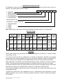
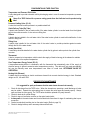
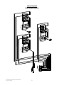
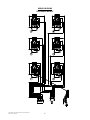
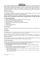
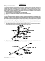
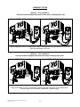
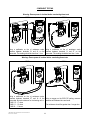
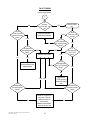
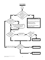
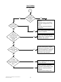
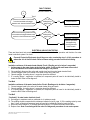
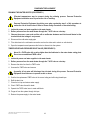
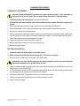
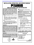
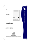
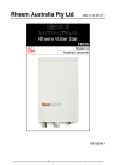
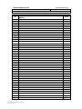
Rheem Australia Pty Ltd
Title: - Service Instructions for Rheem Heavy Duty Electric Water Heaters
Document control header
Document Number: - TM014
Revision
Details of change
D.O.I.
A
Service Instructions issued for Rheem Heavy Duty Electric
Models
07/02
Rheem Heavy Duty Electric Service Instructions REV: A
Date of Issue: 10/7/2002
ELECTRIC
RHEEM AUSTRALIA PTY LTD
SERVICE INSTRUCTIONS
TM014
HEAVY DUTY
ELECTRIC WATER HEATERS
MODELS
613050
613315
616315
610340 – Storage Tank
Rheem Australia Pty Ltd
Revision: A
TM014 Rheem Heavy Duty Electric Service Instructions REV: A
Date of Issue: 10/7/2002
ABN 21 098 823 511
Published: July 2002
1
SAFETY WARNING
The purpose of this Service Manual is to provide sufficient information to allow a person with the skills as
required by the controlling Regulatory Authorities to carry out effective repairs to a Rheem Heavy Duty Electric
Water Heater in the minimum of time.
Safety precautions or areas where extra care should be observed when conducting tests outlined in this
manual are indicated by print in bold italics and/or a warning symbol. Take care to observe the recommended
procedure.
Certain diagnostic procedures outlined in these service instructions require “live” testing to
be conducted. Personal Protective Equipment (PPE) should be worn when conducting these
tests to prevent the risk of electric shock.
WARNING: Voltages up to 415 volts AC may be present (Refer to the Rheem Safety
Procedure on electrical testing)
INTRODUCTION
The information provided in these instructions is based on the water heater being installed in accordance with
the Installation Instructions provided with each water heater.
Should you require further technical advice on a Rheem Heavy Duty Electric Water Heater, contact your
nearest Rheem Service Department where all genuine replacement parts are also available.
CONTENTS
Page
2
3
3
3
4
4
5-6
7-8
8-9
10 - 18
13 - 14
18
19 - 21
22
23
24
25
26
Safety Warning
Model Identification
Specifications
Operation
Components And Their Function
Preventative Maintenance
Wiring Diagrams
Common Faults
Manifolding
Fault Finding
Component Tests
Electrical Insulation Tests
Component Replacement Procedures
Exploded View - Three Element
Exploded View - Six Element
Exploded View – Storage Tank
Replacement Parts List
Warranty Statement
TM014 Rheem Heavy Duty Electric Service Instructions REV: A
Date of Issue: 10/7/2002
2
HEATER MODEL IDENTIFICATION
All identification numbers are designed to convey detailed information about the water heater to which it is
attached. The model number consists of 8 digits.
6
1
6
315
0
8
6 – Heavy Duty
1 – MEPS Compliant
0 – No Heating Units
3 – Three Heating Units
6 – Six Heating Units
Rated Capacity in Litres
No Reference – System Requirement
0 – Element Not fitted
7 – 3600w
8 – 4800w
9 – 6000w
Note: Model number, serial number and date of manufacture should be quoted in all correspondence.
SPECIFICATIONS
T & PR Maximum Inlet
Pressure (kPa) T/stat
Valve
Setting
Rating
Without
(ºC)
With ECV
(kPa)
ECV
Water Connections
Series
Capacity
Rated
Capacity
(Litres)
613
060
50
1000
680
800
75
RP1¼/32 RP¾/20
613
616
340
315
1000
680
800
75
RP1¼/32 RP¾/20
Tradesperson
Adjustable
HEAVY DUTY
Model
1400
610
340
340
1000
680
800
N/A
RP1¼/32 RP¾/20
N/A
1400
Inlet
Outlet
T&PR
T/stat
Type
Anode
Length
(mm)
485
OPERATION
The 613 and 616 series heavy duty electric water heaters are designed for connection to a 3 phase AC supply
incorporating a neutral.
On 3 element models the wiring is configured for one element and thermostat combination to be supplied
between each active conductor (phase) and neutral. On six element models the wiring is configured for two
element and thermostat combinations to be supplied between each active conductor (phase) and neutral.
Water temperature is maintained via the thermostat switching the active conductor to an electric immersion
element. The thermostat and corresponding element are mounted at intervals up the side of the cylinder.
As the water temperature within the cylinder falls the thermostat contacts close suppling power to the element.
Each element is switched on sequentially from the bottom up, as cold water enters the cylinder.
Once the water temperature reaches the set point of the thermostat, the contacts open cutting power to the
corresponding element.
A double pole “manual reset” over temperature cut out is incorporated into each thermostat to provide
additional protection in the event the controlling thermostat contacts fail. The ECO contacts open between
87ºC and 93ºC.
TM014 Rheem Heavy Duty Electric Service Instructions REV: A
Date of Issue: 10/7/2002
3
COMPONENTS AND THEIR FUNCTION
Temperature and Pressure Relief Valve
A valve designed to provide automatic relief by discharging water in case of excessive temperature, pressure
or both.
Never fit a T&PR Valve with a pressure rating greater than that indicated on the product-rating
label.
Pressure Limiting Valve (P.L.V.)
A valve that controls its outlet pressure to a predetermined limit.
Outlet Delivery Tube (Dip Tube)
A plastic tube installed in the hot water outlet of the water heater cylinder to conduct water from the highest
point to the outlet connection. It also acts as a fitting liner.
Diffuser
A plastic device installed in the cold water inlet of the water heater cylinder to assist with stratification. It also
acts as a fitting liner.
Fitting Liner
A plastic tube installed in the cold-water inlet of the water heater to provide protection against corrosion
through the life of the water heater.
Anode (Sacrificial)
A metal alloy electrode installed in the water heater cylinder that by galvanic action protects the cylinder from
corrosion.
Thermostat
A device, responsive to temperature, which controls the supply of electrical energy to the element to maintain
the stored water at the required temperature.
Over Temperature Energy Cutout (E.C.O.)
A temperature-sensing device in combination with the thermostat that automatically cuts off the supply of
electrical energy to prevent excessive water temperature occurring. This device will not reset automatically
but may be manually reset once temperatures have fallen to a safe level. DETERMINE CAUSE OF
OPERATION.
Heating Unit (Element)
A tubular device containing an electric resistance element that converts electrical energy to heat. Standard
ratings are 3.6, 4.8 and 6.0kW
PREVENTATIVE MAINTENANCE
It is suggested for peak performance that the water heater be serviced annually.
1. Check for discharge from the T&PR valve. When the elements are operating a small discharge of water
2.
3.
4.
5.
6.
may be evident. Operate the valve-easing lever to ensure the valve opens and resets properly. Always
open and close the valve gently. The T& PR valve should be replaced at 5 yearly intervals.
Check for leaks at all cylinder fittings.
Check for signs of excessive corrosion on the water heater jacket.
Isolate power to the water heater and check all electrical connections for signs of overheating due to poor
connection.
Conduct an electrical insulation test on the water heater. (Refer to page 18)
Check for sludge build up and if necessary drain and flush tank.
TM014 Rheem Heavy Duty Electric Service Instructions REV: A
Date of Issue: 10/7/2002
4
WIRING DIAGRAMS
THREE ELEMENT MODELS
TM014 Rheem Heavy Duty Electric Service Instructions REV: A
Date of Issue: 10/7/2002
5
WIRING DIAGRAMS
SIX ELEMENT MODELS
TM014 Rheem Heavy Duty Electric Service Instructions REV: A
Date of Issue: 10/7/2002
6
COMMON FAULTS
When a complaint is lodged about the performance of a hot water system there are a number of causes that
should be checked and eliminated. In an attempt to pinpoint the most likely cause it is important to discuss
with the customer their reasons for the complaint, the duration of the problem, any change in circumstances or
usage and recent weather conditions. This information in conjunction with the following listed common
complaints will assist you in locating the most likely cause. All procedures assume there is water flowing
through the water heater.
Excessive hot water usage
The complaints of insufficient hot water and no hot water can on many occasions be attributed to hot water
usage exceeding the capacity of the water heater to provide hot water.
When first attending a call of this nature it is essential to establish the probable hot water usage by querying
the usage habits of the household and compare this with the potential delivery of the model water heater
installed. It can then be established if the usage is within or outside the capacity of the model. The areas to
look at for excessive usage are:
1. Automatic washing machines.
2. Showers exceeding 12 litres/minute for mixed water and 5 minutes in duration.
3. Two or more showers operating at the same time.
4. Change of occupancy or number of persons increased.
5. High water pressure area. (Excessive pressure relief valve discharge)
6. Plumbing leaks
7. Thermostat temperature setting
8. Crossed connection
Discoloured water
This may be the result of discoloured water entering from the cold water mains. Check if the cold water is also
discoloured.
Water hammer
A water heater will not cause water hammer, however valves associated with the water heater may be the
source of the problem i.e. cold -water stopcock, non-return valve or relief valve.
Most water hammer problems are associated with plumbing, hot and cold or appliances i.e. solenoid valves,
ballcocks, loose pipes, sharp angles in pipe work, faulty or worn valve parts, loose tap washers or
neighbouring equipment.
High water pressure areas will have more complaints of this nature and the use of a pressure-limiting valve
(PLV) to reduce the household cold -water pressure will usually solve most problems.
Hot water plumbing leaks
If hot water has not been used for a period of time, feeling the temperature of the hot water line may give an
indication of water flow if the pipe is warm. The method of checking for plumbing leaks is:
1. Turn off the stopcock on the cold water supply to the water heater.
2. Open a hot tap to ensure the flow of water stops. This will confirm the stopcock is operating correctly.
3. Turn off the hot tap.
4. Turn on the stopcock to make up the water pressure in the cylinder, and then turn the stopcock off again.
5. Wait approximately 5 minutes then do either of the following:
a. With your ear close to the stopcock turn it on slightly and listen for any water passing. If there are no
leaks, water should not pass.
b. Open a hot tap while listening for any pressure release. If there is a pressure release there will be no
leaks in the plumbing system.
TM014 Rheem Heavy Duty Electric Service Instructions REV: A
Date of Issue: 10/7/2002
7
COMMON FAULTS
Mixing or crossed connections
If an automatic dishwasher, washing machine, flick mixer tap, tempering valve or thermostatic mixing valve is
installed there is always the possibility that the cold water could mix with the hot water through a faulty or
incorrectly installed valve. This is referred to as a cross connection. The complaints of insufficient hot water,
water too cold or excessive discharge from the pressure relief valve may be attributed to a cross connection.
The method of checking for a cross connection is:
1. Turn off the stopcock on the cold water supply to the water heater.
2. Open a hot tap. If water flow is persistent and cold a cross connection exists.
Manifolding
Very often complaints surrounding insufficient hot water in commercial installations can be attributed to poor
manifolding. In order for the water heaters to operate simultaneously the water flow through all the tanks must
be the same to ensure the temperature drop is equal across the tanks. In a worst-case scenario it is possible
for 2 or 3 of the water heaters in a bank to almost never operate. This results in an overall loss of heat input to
the water moving through the building and can be confused as the installation being undersized or a
malfunction of the water heaters. The principle of Equa-Flow is to ensure the demand on each water heater in
the bank is the same as any other. To achieve this, the following are necessary:
1. The cold water manifold must be designed to balance the flow to each unit i.e. each branch line must be
the same diameter and length and be fitted with identical ball or gate valves.
2. The hot water manifold must be designed to balance the flow from each unit i.e. each branch line must
be the same diameter and length and be fitted with identical ball or gate valves.
TM014 Rheem Heavy Duty Electric Service Instructions REV: A
Date of Issue: 10/7/2002
8
COMMON FAULTS
Manifolding
3. All the water heaters must be of the same size and capacity.
4. The first heater supplied from the cold (inlet) manifold must be the last heater supplying the hot (outlet)
manifold (see examples below).
In Line Manifold
Back to Back Manifold
TM014 Rheem Heavy Duty Electric Service Instructions REV: A
Date of Issue: 10/7/2002
Angle Manifold
9
FAULT FINDING
Fault Diagnosis
Is
the complaint
for no hot
water?
YES
1
NO
Is
the complaint
for insufficient hot
water?
YES
2
YES
3
YES
4
NO
Is
the complaint
for leaking water
heater?
NO
Is
the complaint
for water too
hot ?
NO
Noisy water heater
TM014 Rheem Heavy Duty Electric Service Instructions REV: A
Date of Issue: 10/7/2002
10
5
FAULT FINDING
No hot water
1
Warning: Terminals may be live,
Personal Protective Equipment
should be worn.
Is
240/415 volts
present at the terminal
NO
block?
Test 1 & Test 2
Restore power and
advise customer
YES
YES
Is
the isolating switch
turned off?
NO
Possible fault in building
electrical wiring, continue
with diagnosis to confirm
water heater is operational
NO
Is the
fuse(s) blown at the
switchboard?
YES
Isolate power and reconnect correctly.
Follow flow chart 2 to diagnose any
damaged components
YES
Test 1
Has
the heater
been connected
incorrectly?
i.e. Active connected to Neutral terminal
NO
Test 3, 4 and 5
Isolate power and
continue with diagnosis
procedure
NO
Using the procedure on
page 18 conduct an
electrical insulation test
Is the
reading below 1
mega-ohm?
YES
2
TM014 Rheem Heavy Duty Electric Service Instructions REV: A
Date of Issue: 10/7/2002
6
11
FAULT FINDING
With multi -element water heaters very often more than one fault may have occurred before the user feels the
effect. When servicing a multi-element water heater each thermostat - element combination should be
checked to ensure correct operation. In manifolded installations a complaint for insufficient hot water may be
due to faults in more than 1 heater or may be a result of poor manifolding.
Insufficient Hot Water
2
Test 6
Are
the thermostat
ECO contacts
closed ?
NO
Is
the element
installed in the correct
orientation?
YES
Test 7
Are
the thermostat
contacts
closed ?
NO
NO
Install the element
correctly and reset the
ECO
YES
Replace thermostat
Is
the temperature
at the T&PR valve at
YES
Replace thermostat
least 6 degrees lower than
the thermostat
Note: Depending on the stratification some
setting?
NO
YES
thermostats may be open and some closed.
Ensure the next step is followed to correctly
diagnose a faulty thermostat.
Slide the thermostat out from under the
retaining clamp and allow base to cool
YES
Test 8
Does
the element
have the correct
resistance?
Test 7
Did
the thermostat
contacts
close?
NO
Replace thermostat
NO
Replace element
Repeat diagnoses
for each water heater
YES
Repeat diagnoses for each
thermostat element
combination
Is
more than
1 water heater
installed?
YES
NO
TM014 Rheem Heavy Duty Electric Service Instructions REV: A
Date of Issue: 10/7/2002
12
2
Water heater
electrically ok.
Refer to manifolding
section
COMPONENT TESTING
Warning – “Live” equipment
Personal Protective Equipment should be worn when conducting these tests.
TEST 1 – 3 Element Models
TEST 1 – 6 Element Models
Using a multimeter on the AC voltage scale, measure between each active and neutral on the terminal
block. Normal voltage is 240 volts
Warning – “Live” equipment
Personal Protective Equipment should be worn when conducting these tests.
TEST 2 – 3 Element Models
TEST 2 – 6 Element Models
Using a multimeter on the AC voltage scale, measure between each active on the terminal block.
Normal voltage is 415 volts when connected to a 3-phase supply.
TM014 Rheem Heavy Duty Electric Service Instructions REV: A
Date of Issue: 10/7/2002
13
COMPONENT TESTING
Warning: Ensure power is isolated before conducting these tests
TEST 6
TEST 7
Using a multimeter on the x1 resistance scale, Using a multimeter on the x1 resistance scale,
measure between terminals 3L and 4L on the measure between terminals 1L and 2T on the
thermostat. The reading should be less than 1 ohm thermostat. The reading should be less than 1 ohm.
Warning: Ensure power is isolated before conducting these tests
TEST 8
TEST 9
Using a multimeter on the x1 resistance scale,
measure between terminals 2T and 4L of the Using a megger on the 500V DC setting, measure
thermostat. Normal resistance for the heating unit is: between each element wire and earth.
3.6kW: 15 - 17 ohms
4.8kW: 11 - 13 ohms
The resistance should be greater than 1 mega ohm
6.0kW: 9 – 11 ohms
TM014 Rheem Heavy Duty Electric Service Instructions REV: A
Date of Issue: 10/7/2002
14
FAULT FINDING
Leaking Water Heater
3
Is
the leak
from or near the
top?
NO
Is the
leak from the
electrical access
cover?
Remove anode and
reseal with thread tape
YES
YES
YES
NO
Is
the leak from
the T & PR
valve?
YES
Replace water heater
NO
Is the
leak from the
anode?
Is
the leak from
the anode cylinder
fitting?
NO
Is
the leak from
the element barrel
fitting?
Remove anode
cap
YES
YES
NO
Remove element and
replace gasket
YES
Is
the leak from
the T & PR cylinder
fitting?
NO
NO
YES YES
Is
the leak from
the inlet cylinder
fitting?
NO
TM014 Rheem Heavy Duty Electric Service Instructions REV: A
Date of Issue: 10/7/2002
Check for hot spots on
the jacket. If any are
detected conduct a
pressure test.
Replace water heater if
pressure will not hold
15
Remove the
T & PR valve and
reseal with thread
tape
NO
Is
the leak from
the outlet cylinder
fitting?
FAULT FINDING
Water too hot
4
Does
the water
temperature at
the T&PR valve correspond
with or near the
thermostat
setting?
NO
Is
the thermostat
in good contact with the
cylinder?
YES
NO
Remove the thermostat and clean
any scale from the cylinder wall.
Re-tension bracket and refit
thermostat
YES
Explain to customer the reasons for
storing water hotter than they may desire
i.e.
(A) When mixed with cold water more hot
water delivery is possible.
(B) Prohibit bacteria growth
Tempering limiting devices should be
suggested as a solution
Test 6
Are
the thermostat
ECO contacts
closed?
NO
Test 7
Are
the thermostat
contacts
closed?
Reset the ECO
YES
Replace thermostat
YES
Repeat test for each thermostat
and element combination
NO
Is
the element
installed in the correct
orientation?
NO
YES
TM014 Rheem Heavy Duty Electric Service Instructions REV: A
Date of Issue: 10/7/2002
16
Refit element correctly
Replace thermostat
FAULT FINDING
Noisy Water Heater
5
NO
Is
the noise
only evident during
the heating
cycle?
Is
the noise water
hammer?
NO
Is the
noise only
evident when water
is flowing through
the water
heater?
YES
Check for:
(A) Mineral build up on the element
(B) Mineral or sludge build up in the
cylinder
(C) Normal noises associated with
heating water
YES
Refer to water hammer causes on page
7, common complaints
NO
Check all other appliances that can
generate noise i.e. washing machine,
dishwasher, ball cocks etc.
YES
Cylinder contracting due to pressure
release when hot tap opened. This can
also be accompanied by a creaking or
cracking sound from the insulation.
This noise is normal operation
NO
Check for a faulty stop cock, non-return
valve or T&PR valve
YES
Check for restrictions in pipe work,
faulty valves, loose plumbing or other
appliances i.e washing machine or
dishwasher.
Fit 600kPa pressure limiting valve
YES
Is
the noise
a metallic popping
sound?
NO
Is
the water
pressure more than 80%
of the T & PR valve
rating?
TM014 Rheem Heavy Duty Electric Service Instructions REV: A
Date of Issue: 10/7/2002
17
FAULT FINDING
Electrical Insulation Test
6
Test 9
Is the
reading below 1
mega-ohm?
Disconnect the leads to the element
from the thermostat and megger
between each element lead and earth
YES
Rewire fuse if necessary
NO
Disconnect remaining leads from the
thermostat and megger between each
terminal on the thermostat and earth
Replace element
Is the
reading below 1
mega-ohm?
YES
Replace thermostat
Rewire fuse if necessary
NO
Check for pinched or
damaged wiring
touching the water
heater chassis
ELECTRICAL INSULATION TESTING
There are three basic test procedures that should be carried out when the operation and function of a water
heater’s electrical system is in doubt.
Personal Protective Equipment should be worn when conducting step 1 of this procedure to
reduce the risk of electric shock. Refer to Rheem safety procedure on electrical testing.
Test No.3
Insulation resistance of the water heater Neutral Circuit. (Reading not to be below 1 mega-ohm).
1. Isolate power to the water heater at the isolation switch. Confirm with multi-meter across each
Active and Neutral at the terminal block that voltage is not present.
2. Once satisfied, disconnect the active and neutral wires from the water heater terminal block.
3. Connect megger leads to the neutral of the water heater wiring and earth.
4. Operate megger. A reading above 1 mega-ohm should be obtained.
5. If a reading below 1 mega-ohm is indicated, all component parts will need to be individually tested to
locate the fault. Refer to flow diagram 6.
Test No.4
Insulation resistance of the water heater Active Circuit. (Reading not to be below 1 mega-ohm).
6. Connect megger leads to the active of the water heater wiring and earth.
7. Operate megger. A reading above 1 mega-ohm should be obtained.
8. If a reading below 1 mega-ohm is indicated, all component parts will need to be individually tested to
locate the fault. Refer to flow diagram 6.
Test No.5
“Continuity” of water heater electrical circuit.
9. Set megger to resistance scale or multimeter to x1 resistance scale.
10. The reading should correspond with resistances indicated in test 8, page 14. If the reading varies by more
than 2 ohms, all electrical component parts will need to be individually tested to locate the fault.
11. Reconnect active cables to ”A” terminal and neutral cable to “N” terminal at heater terminal block.
12. Replace fuse. Note: If continuing with flow chart 2 of diagnostic procedure do not restore power.
TM014 Rheem Heavy Duty Electric Service Instructions REV: A
Date of Issue: 10/7/2002
18
COMPONENT REPLACEMENT
DRAINING THE WATER HEATER (PROCEDURE 1)
Elevated temperatures may be present during the draining process. Personal Protective
Equipment should be worn to prevent the risk of scalding.
Personal Protective Equipment should be worn when conducting step 3 of this procedure to
reduce the risk of electric shock. Refer to Rheem Safety Procedure on electrical testing.
1. Isolate the power and water supplies to the water heater.
2. Relieve pressure from the water heater through the T & PR valve or a hot tap.
3. Remove the access cover and confirm with a multi-meter between each Active and Neutral at the
terminal block that voltage is not present.
4. Disconnect the cold water supply pipe
5. Fit a drain hose to the cold-water connection and run the other end to a drain or safe location.
6. Open the temperature and pressure relief valve to allow air into the system.
TEMPERATURE AND PRESSURE RELIEF VALVE (PROCEDURE 2)
Never fit a T&PR valve with a rating higher than that indicated on the water heater rating plate.
Do not use reconditioned T&PR valves.
1. Isolate the power and water supplies to the water heater.
2. Relieve pressure from the water heater through the T & PR valve or a hot tap.
3. Remove the drain line from the T&PR valve.
4. Unscrew the T&PR valve and remove.
A quantity of hot water will discharge from the tank during this process. Personal Protective
Equipment should be worn to prevent scalds or burns.
5. Confirm the replacement T&PR valve is the correct rating and refit using thread tape.
6. Refit the drain line.
7. Close the hot tap and restore water supply.
8. Check T&PR valve thread for leaks.
9. Operate the T&PR valve lever to reset relief drain.
10. Purge air from the system through hot taps.
11. Restore the power supply to the water heater.
TM014 Rheem Heavy Duty Electric Service Instructions REV: A
Date of Issue: 10/7/2002
19
COMPONENT REPLACEMENT
THERMOSTAT (PROCEDURE 3)
Personal Protective Equipment should be worn when conducting step 2 of this procedure to
reduce the risk of electric shock. Refer to Rheem Safety Procedure on electrical testing.
1. Isolate the power to the water heater and remove access cover.
2. Confirm with multi-meter between each Active and Neutral at the terminal block that voltage is not
present.
3. Remove the thermostat protective cover and disconnect the wiring from the thermostat.
4. Slide the thermostat out from under the retaining clamp. Note the current temperature selected.
5. Remove any scale from the cylinder surface
6. Slide the replacement thermostat under the clamp and set temperature to that noted in step 4. Reconnect
the wiring as per the circuit diagram (3 element models refer to page 5. 6 element models refer to page 6.)
7. Check water heater internal wiring insulation for cracking.
8. Conduct an electrical insulation test. Refer to page 18.
9. Refit the thermostat protective cover and the access cover.
10. Restore the power supply.
DIP TUBE (PROCEDURE 4)
1. Isolate the power and water supplies to the water heater.
2. Relieve pressure from the water heater through the T & PR valve or a hot tap.
3. Disconnect the hot water line from the outlet of the water heater.
A quantity of hot water will discharge from the outlet during this process. Personal Protective
Equipment should be worn to prevent scalds or burns.
4. Using a flat blade screwdriver gently split the outer rim at the top and bottom of the dip tube face and prise
the dip tube out of the cylinder fitting.
5. Fit the replacement dip tube into the cylinder fitting ensuring the flat lines up with the fitting (dip tube facing
up) and gently drive the dip tube into the fitting a short distance.
6. Reconnect the plumbing, this will push the dip tube into the correct location.
7. Restore the water supply and purge air from the system through hot taps.
8. Restore the power supply.
TM014 Rheem Heavy Duty Electric Service Instructions REV: A
Date of Issue: 10/7/2002
20
COMPONENT REPLACEMENT
ANODE (PROCEDURE 5)
Elevated temperatures may be present during anode removal process. Personal Protective
Equipment should be worn to prevent the risk of scalding.
1. Isolate the power and water supplies to the water heater.
2. Relieve pressure from the water heater through the T & PR valve or a hot tap.
3. Remove the anode cap.
4. Using a 27mm tube or socket spanner remove the anode.
5. Apply thread seal tape to replacement anode, refit and tighten. Note: It may be necessary to cut the anode
to length prior to fitting. Refer to page 3 for the correct anode length.
6. Restore water supply and check for leaks.
7. Refit the anode cap.
8. Purge air from the system through hot taps and restore the power supply to the water heater.
ELEMENT (PROCEDURE 6)
Elevated temperatures may be present during element removal process. Personal Protective
Equipment should be worn to prevent the risk of scalding.
Personal Protective Equipment should be worn when conducting step 2 of this procedure to
reduce the risk of electric shock. Refer to Rheem Safety Procedure on electrical testing.
Where a fault or leak is traced to the element, the water heater should be drained to prevent damage to
flooring or floor coverings by accidental flooding.
1. Isolate power and water supplies and remove the access cover.
2. Confirm with a multi-meter between each Active and Neutral at the terminal block that voltage is
not present.
3. Relieve pressure from water heater through the T & PR valve or a hot tap.
4. Drain the water heater. Refer to procedure 1 on page 19.
5. When the water heater is drained, undo the four element screws, removing thermostat clamp first.
6. Withdraw heating unit. Care must be taken to ensure the loop of the heating unit does not catch in the
cylinder opening and open out inside the cylinder.
NOTE: Do not “cut off” the heating unit and leave a portion inside the cylinder
7. Clean around cylinder fitting, fit gasket to new element and slide heating unit into cylinder taking care that
it is in the correct orientation. See heating unit plate for directions.
8. Replace screws and thermostat clamp and tighten.
9. Restore cold water supply and fill the storage tank by gently lifting the easing lever on the T & PR valve
until water runs from the drain.
10. Check for water leaks around the element flange.
11. Conduct an electrical insulation test. (Refer to page 18)
12. Replace access cover securely and restore electrical supply.
TM014 Rheem Heavy Duty Electric Service Instructions REV: A
Date of Issue: 10/7/2002
21
EXPLODED VIEW – THREE ELEMENT MODELS
TM014 Rheem Heavy Duty Electric Service Instructions REV: A
Date of Issue: 10/7/2002
22
EXPLODED VIEW – SIX ELEMENT MODELS
TM014 Rheem Heavy Duty Electric Service Instructions REV: A
Date of Issue: 10/7/2002
23
EXPLODED VIEW – STORAGE CYLINDER
TM014 Rheem Heavy Duty Electric Service Instructions REV: A
Date of Issue: 10/7/2002
24
REPLACEMENT PARTS LIST
Item
1
2
3
4
5
6
Description
Fitting Liner – Inlet
Pipe Seal – Inlet/Outlet
Access Cover
Adaptor Flange and Pipe
Element Screw
Element Blanking Plate
Element (Incoloy)* - 3.6kW
7 Element (Incoloy)* - 4.8kW
Element (Incoloy)* - 6.0kW
8 Thermostat Clamp
9 Element Gasket
10 Thermostat
11 Terminal Block
12 Jacket Bottom
13 T & PR Valve (H.T.E 1000kPa)
14 Fitting Liner – T & PR
15 Pipe Seal – T & PR
16 Jacket Top
Anode – Black
17 Anode – Blue
Anode – Green
18 Anode Cover
19 Name Band
20 Dip Tube (Outlet)
* Mandatory on all heavy duty models
TM014 Rheem Heavy Duty Electric Service Instructions REV: A
Date of Issue: 10/7/2002
613050
229450
221406-1
103411-1
NF
051404
NF
050254
050255
050256
102501
050704
051314
051510
100526-1
220604
229460
221392-1
100622-1
222023
222033
222037
221720-1
120493
220510
25
613315
229455
221406-1
103511-1
NF
051404
NF
050254
050255
050256
102501
050704
051334
051510
100642-1
220604
229460
221404-1
100647-1
222021
222031
222035
221720-1
120492
220511
616315
229455
221406-1
103512-1
NF
051404
NF
050254
050255
050256
102501
050704
051334
051706
100642-1
220604
229460
221404-1
100647-1
222021
222031
222035
221720-1
120492
220511
610340
229455
221406-1
100766-1
299504
051404
051005
NF
NF
NF
NF
050704
NF
NF
100642-1
220604
229460
221404-1
100647-1
221915
221925
222015
221720-1
120491
220511
RHEEM ELECTRIC WATER HEATER WARRANTY - (AUSTRALIA ONLY)
Rheem Australia will:
a) Repair or, if necessary replace any Rheem water heater; or
b) Replace any component (or, if necessary, arrange the installation of a new water heater),
which falls within the Warranty Periods specified below, in accordance with and subject to the following table, conditions and
exclusions.
Installation
Models
Period
Warranty
Component and cylinder warranty (from date of installation)
New component or water heater free of charge,
All installations
All models
12 months
including labour**
Inner cylinder warranty (from date of installation)
Years 2 and 3 New water heater free of charge, including labour**
Rheemglas
New water heater free of charge with installation and
Water heater installed in “a single- family
Years 4 and 5
labour costs being the responsibility of the owner.
domestic premises with a thermostat
Years
2
5
New water heater free of charge, including labour**
setting below 76ºC”
Optima and
New water heater free of charge with installation and
Heavy Duty
Years 6 - 10
labour costs being the responsibility of the owner
Water heater installed in any other than
“a single- family domestic premises with
a thermostat setting below 76ºC”
Rheemglas
Years 2 and 3
Optima and
Heavy Duty
Years 2 - 5
New water heater free of charge with installation and
labour costs being the responsibility of the owner
Notes:
** Refer to item 4 of warranty conditions.
Rheem Australia reserves the right to transfer fully functional components from the defective water heater to the replacement water heater if required.
WARRANTY CONDITIONS
1.
2.
3.
4.
This warranty is applicable only to Rheem water heaters manufactured
from 1st January 2001.
The water heater must be installed in accordance with the Rheem water
heater installation instructions, supplied with the water heater, and in
accordance with all relevant statutory and local requirements of the State in 5.
which the water heater is to be installed.
Where a failed component or water heater is replaced under Warranty, the
balance of the original period will remain effective. The replaced part or
water heater does not carry a new warranty.
Where the water heater is installed outside the boundaries of a 6.
metropolitan area as defined by Southcorp or further than 25 km from a
regional Southcorp Water Heaters Australia branch office, or an
Accredited Service Agent, the cost of transport, insurance and travelling
costs between the nearest Southcorp Water Heaters Australia Accredited
Service Agent’s premises and the installed site shall be the owner’s
responsibility.
The warranty only applies to the water heater and original or genuine
company component replacement parts and therefore does not cover any
plumbing or electrical parts supplied by the installer and not an integral
part of the water heater, e.g. pressure limiting valve; isolation valves; nonreturn valves; electrical switches; pumps or fuse.
The water heater must be sized to supply the hot water demand in
accordance with the guidelines in Rheem water heater literature.
WARRANTY EXCLUSIONS
REPAIR AND REPLACEMENT WORK WILL BE CARRIED OUT AS SET OUT IN THE RHEEM WATER HEATER WARRANTY
ABOVE, BUT THE FOLLOWING EXCLUSIONS MAY CAUSE THE WATER HEATER WARRANTY TO BECOME VOID, AND
MAY INCUR A SERVICE CHARGE AND COST OF PARTS.
1.
a)
b)
2.
Accidental damage to the water heater or component including: Acts of
God; failure due to misuse; incorrect installation; attempts to repair the
water heater other than by a Southcorp Accredited Service Agent or the
Southcorp Water Heaters Australia Service Department.
Where it is found there is nothing wrong with the water heater; where the
complaint is related to excessive discharge from the temperature and
pressure relief valve due to high water pressure; where there is no flow of
hot water due to faulty plumbing; where water leaks are related to
plumbing and not the water heater components; where there is a failure of
gas, electricity or water supplies; where the supply of gas, electricity or
water does not comply with relevant codes or acts.
c)
d)
e)
Where the water heater or water heater component has failed directly or
indirectly as a result of: excessive water pressure, temperature and/or
thermal input or corrosive atmosphere.
Where the water heater is located in a position that does not comply
with the Rheem water heater installation instructions or relevant
statutory requirements, causing the need for major dismantling or
removal of cupboards, doors or walls, or use of special equipment to
bring the water heater to floor level.
Repairs to the water heater due to scale formation in the waterways
when the water heater has been connected to a harmful water supply as
outlined in the Owner’s Guide and Installation Instructions booklet.
SUBJECT TO ANY STATUTORY PROVISIONS TO THE CONTRARY, THIS WARRANTY EXCLUDES ANY AND ALL CLAIMS
FOR DAMAGE TO FURNITURE, WALLS, FOUNDATIONS OR ANY OTHER CONSEQUENTIAL LOSS EITHER DIRECTLY
OR INDIRECTLY DUE TO LEAKAGE FROM THE WATER HEATER.
In addition to this warranty, the Trade Practices Act 1974 and similar laws in each state and territory provide the owner under certain circumstances with certain
minimum statutory rights in relation to your Rheem water heater. This warranty must be read subject to that legislation and nothing in this warranty has the effect of
excluding or restricting those rights.
Rheem Australia Pty Ltd
FOR SERVICE TELEPHONE
131 031 AUSTRALIA
0800 657 335 NEW Zealand
A.B.N 21 098 823 511
or refer local Yellow Pages
NOTE: Every care has been taken to ensure accuracy in preparation of this publication. No liability can be accepted for any consequences, which may arise as a
result of its application.
TM014 Rheem Heavy Duty Electric Service Instructions REV: A
Date of Issue: 10/7/2002
26