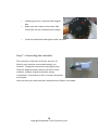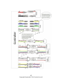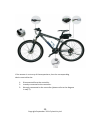
1
eKit User Manual
Cyclotricity Electric Bike Conversion Kit
September 2011 1st edition
1
Copyright September 2011 Cyclotricity Ltd
Preface
The Cyclotricity eKit is supplied as a set of do-it-yourself parts for
the user to install on their bicycle. Because this kit is installed,
maintained and operated by the purchaser, Cyclotricity Ltd
disclaims any responsibility for injury, damage or other
consequences arising from the use of this product. Each installation
will be different and therefore it is the responsibility of the
purchaser to determine the best way to install the kit on their
particular bicycle. The following instructions should be considered
as general guidelines only – your installation will be slightly
different.
If you do not have the mechanical ability to correctly and safely
install this kit, you should obtain the services of a professional
bicycle shop or other qualified technician. Installation and use of
this kit will create a vehicle that has exposed moving parts,
electrical connections and high powered batteries.
Any or all of these components can be dangerous.
2
Copyright September 2011 Cyclotricity Ltd
Contents
Part 1 – Before Installation
-
Page
Disclaimer
Battery care
Charger
Water
Specifications
Warranty
Exceptions to Waranty
4
4
6
6
7
7
8
Part 2 – Installation Guide
-
Step 1 – Opening your eKit box
Step 2 – Charge the battery
Step 3 – Conversion tools
Step 4 – Replacing the front wheel
Step 5 – Throttle and breaks levers
Step 6 – Pedal Assistance System
Step 7 – Controller
Step 8 – Battery Rack
Step 9 – Test
Step 10 – Final touches
10
11
11
11
13
15
17
18
19
21
Part 3 – Troubleshooting
-
Troubleshooting
22
3
Copyright September 2011 Cyclotricity Ltd
Part 1 – Before Installation
Disclaimer
The Cyclotricity eKit is supplied as a set of do-it-yourself parts for
the user to install on their bicycle. Because this kit is installed,
maintained and operated by the purchaser, Cyclotricity Ltd
disclaims any responsibility for injury, damage or any other
consequences arising from the use of this product.
Each installation will be different and therefore it is the
responsibility of the purchaser to determine the best way to
install the kit on their particular bicycle. The provided instructions
should be considered as general guidelines only – every electric
bike conversion will be slightly different. If you do not have the
mechanical ability to correctly and safely install this electric bicycle
conversion kit, you should obtain the services of a professional
bicycle shop or other qualified technician.
Installation and use of this e-bike conversion kit will create an
electric motor vehicle that has exposed moving parts, electrical
connections and high powered batteries. Any or all of these
components can be dangerous!
Battery care
1- The battery is detachable and comes with a key to lock it
in place. Please note that the battery lock is only meant to
prevent it from falling off during cycling and should not be
regarded as a security lock against theft. We recommend
you detach the battery and carry it with you whenever you
4
Copyright September 2011 Cyclotricity Ltd
leave the bike in public places as it is the most expensive
part in your product to replace.
2- Before you use the battery for the first time it is best to
give it a full deep charge for 12 hours. To fully condition
your new battery give it complete deep charge, discharge
cycles for the first three charges. This is achieved by
charging your battery for 12 hours and then using the bike
until the battery is completely drained.
After this “conditioning” process, you can leave the
battery charging as and when you require.
3- If you are going to leave your battery uncharged for more
than eight weeks it is best left half charged. You should
then re charge it every four weeks for two hours to keep it
in top condition.
4- Check the indicators on the actual battery to see how
much power you have left.
Please note that the indicators on the handlebar
dashboard (if purchased) lights do not necessarily show
the amount of power you have left, but the amount of
load the battery is experiencing at any one point. If the
lights go down to “Empty”, then this is a strong indication
that you ought to be pedaling more to take some of the
load off the battery. This will improve the battery life
cycle.
5- Do not expose the bicycle or battery pack to fire, heat
sources, acid or alkaline substances.
6- For best results, always charge the battery at room
temperature.
7- Always make sure the battery is turned off before
detaching/connecting it.
5
Copyright September 2011 Cyclotricity Ltd
8- If your battery is damaged or appears to be overheating
for any reason immediately return it to your retailer for
advice and a safety check.
Charger
1- Red light on the charger means the battery is charging.
When the red light turns green, the battery is fully
charged. Please ignore the green light and carry on
charging for 12 hours for the first 3 charges to condition
your battery.
2- Always disconnect the charger from the mains before
disconnecting the charger from the battery.
3- Do not leave the charger connected to the mains when
not in use.
Water
Your eKit is rain and splash resistant and can be used in all
weathers. The electrical components of the vehicle, such as motor,
battery, and controller, must not be submerged in water.
WARNING: Do not attempt to open the casings of the battery or
motor as it could be dangerous and all warranties will become void.
If you experience problems, refer to the troubleshooting guide in
this manual or ask your local dealer.
6
Copyright September 2011 Cyclotricity Ltd
Specifications
Battery range (based on 36V/7Ah): 20-30km between charges
depending on terrain, weight of cyclists, frequent use of pedals,
frequency of stops/starts, air pressure in tires etc.
Battery type: Lithium-ion
Speed: 25km/h (15.5mph)
Motor type: High speed brushless geared hub motor
Motor power: 250W
Motor voltage: 36V
Warranty
Only use this product in accordance with this user manual. We
offer a 1 year warranty on all items inside your eKit box. The
warranty only covers technical faults which have not been in
anyway caused by the user deliberately or accidentally.
Those parts and/or products which are determined by Cyclotricity
to be defective and to qualify for warranty replacement will be
provided at no charge, only after a valid warranty claim is
processed by Cyclotricity.
Warranty claims must be made by the original purchaser by
contacting the original Cyclotricity dealer within the warranty
period. Shipping & Handling fees will apply to all orders placed for
warranty parts and/or products and will be invoiced to the
7
Copyright September 2011 Cyclotricity Ltd
customer/warranty claimant prior to said parts and/or products are
shipped from Cyclotricity.
Cyclotricity, at its sole discretion, has the option of replacing with a
new part, or factory re-certified part. The Limited Warranty stated
herein is in lieu of and expressly excludes all other warranties not
expressly set forth herein, whether expressed or implied by law or
otherwise, including, but not limited to, any warranties for
merchantability and/or fitness for any particular purpose.
Cyclotricity shall in no event be liable or responsible for incidental
or consequential losses, damages or expenses in connection with
their products. The liability of Cyclotricity hereunder is expressly
limited to the replacement of goods complying with this warranty
or at the sole discretion of Cyclotricity to the repayment of an
amount equivalent to the purchase price of the part in question.
NOTE: Damage caused by water, dropping or any collision is NOT
covered.
Exceptions to limited Warranty
“Spin Out” – Spinning out the axles inside of your dropouts – We
are unable to be there when the kit is installed so it is up to you to
understand the high torque involved at the dropouts and install
them correctly.
If your dropouts are not correctly suited to fit the axle then you
should not install the kit on those forks. Get new forks, file the
forks to the axle fit “flush” or contact your dealership to return the
kit. We will not refund or replace a motor that has been “spun
out”.
8
Copyright September 2011 Cyclotricity Ltd
“Over Voltage” – Connecting a battery larger than 36 volts can
damage the controller, wires and/or connectors. Damaging any kit
component or motor by connecting the wrong battery type will
void the warranty. The Cyclotricity eKit will work with a 36 volt
Lithium-ion battery pack only. We strongly recommend the use of a
Cyclotricity battery for best compatibility and performance.
Water Damage The warranty does not include damage from power surges, use of
improper charger, improper maintenance or other such misuse, or
normal wear. The Cyclotricity eKit parts are water resistant and fine
in the rain but should NEVER be submerged in liquid.
9
Copyright September 2011 Cyclotricity Ltd
Part 2- Installation Guide
Step 1 – Opening your eKit box
Inside your box, you should find the following parts:
123456-
Thumb throttle
Controller
A pair of electric brake levers
Battery, battery holder and a charger (usually in a separate box)
Pedal Assistance Sensor (if you have chosen to upgrade your kit
with this function)
Handlebar dashboard (if you have chosen to upgrade your kit
with this function)
10
Copyright September 2011 Cyclotricity Ltd
Step 2 – Charge the battery
Start by charging the battery for at least 12 hours before first time use (see
Battery Care section in this manual). In subsequent charges, however, you
only need to wait until the red indicator turns green on the charger (which
is usually within 5 hours).
Step 3 – Conversion tools
The following tools are needed to install the eKit:
12345-
10mm wrench
5mm, 3mm and 2.5mm hex keys
Pump
Flat and crossed screw drivers
Crank extractor (this is a bike-specific tool. You only need this if
you decided to upgrade your kit with a Pedal Assistance System)
Step 4 – Replacing the front wheel
Note: The hub motor comes with 6 holes
and bolts that are compatible with the
majority of brake discs. If your bike is
equipped with a front disc brake instead of
a V-brake, then your motor should look as
illustrated to the right before assembly.
Afterwards:
o
o
o
o
Start by turning your bike upside down so it is resting on the
saddle and handlebars.
Unscrew the nuts and remove the front wheel.
Remove the tyre, air-tube and protection stripe. Place them on
the motor wheel instead.
Loosen the nuts on the motor wheel and insert it in place of the
old wheel.
11
Copyright September 2011 Cyclotricity Ltd
IMPORTANT: If your bike is resting upside down, make sure the
motor cable is pointing to the left hand side of the fork as shown
in this picture:
o
o
You will notice that there is an unusual washer with a small
axle sticking out (called torque washer) placed on the motor
spindle.
Make sure that the axle slides inside the fork drop-out like so:
12
Copyright September 2011 Cyclotricity Ltd
IMPORTANT: Make sure that the torque washer fits firmly inside the fork
dropt-outs and is completely stable. If the torque washer doesn’t fit
properly, contact a local bike service shop for assistance on finding a
different washer or replacing the fork altogether. Remember that damage
caused by motor “spin outs” is not covered by the warranty.
o
Make sure a normal washer is inbetween the fork and the nut. Tighten
the nut using an 8-10mm wrench as
tight as you can without damaging the
fork.
WARNING: Be extra careful with alloy
forks.
Step 5 – Installing the throttle and brake levers
o
o
o
o
o
Remove the rubber grips off your bike’s handlebar.
Tip: If this proves a challenge, try mixing washing up liquid in
a bowl of water and soak a towel in it. Use a flat screw
driver to force a small opening from under the grip and
squeeze the soapy liquid in. Be careful not to scratch the
handlebar.
Remove the brake wire from the brake levers.
Remove the brake levers from the handlebar.
Replace them with the electric brake levers supplied with
your kit.
Insert the brake wires in the new electric levers.
13
Copyright September 2011 Cyclotricity Ltd
o
Tighten the levers to the handle bar using a 5mm hex key.
Note: The width of your motor rim might be different from your
original rim. If your bike is fitted with a front V-brake, this would
need to be adjusted. Hold the brake pads against the rim and
tighten using a hex key or a wrench depending on the type of
brake you have. (If there isn’t enough slack, loosen the wire bolt
until there is about 1/8” of play and re-tighten).
14
Copyright September 2011 Cyclotricity Ltd
o
o
Mount the throttle and tighten using a
2.5 hex key.
Note: Before tightening, consider the
positions of the brake levers and any
gear shifters you may have. Determine
the best order in which these three
controls are mounted on the handlebar
for best reach and ease of use.
If you have upgraded your kit with either and LED or LCD
Dashboard, mount this on the handlebar the same way you did
with the other controls.
Step 6 – Installing the Pedal Assistance System (for upgrades
only)
Please skip through to step 7 if you haven’t upgraded your kit to pedal
assist yet. This is the only device where you will need a bike-specific tool,
namely a Crank Extractor. If you do not have access to this tool, you can
ask any local bike shop to perform this step for you.
o
o
o
o
Use a crank extractor to remove the LEFT
crank arm.
You will then find a washer-like lock on the
axle (called bottom bracket lock), remove
this too.
Put the PAS sensor unto the end of the
bottom bracket. Make sure the sensor
device is facing outwards.
Lock the sensor by putting the lock back (see image).
15
Copyright September 2011 Cyclotricity Ltd
o
o
o
Following the lock, insert the PAS magnet
disc.
Make sure the arrows on the outer side
of the disc are anti-clockwise (see image).
Install the pedal back and tighten with a wrench.
Step 7 – Connecting the controller
The controller is the brain of the kit. As such, all
electric parts must be connected through it to
function. Though the connectors may slightly vary
from the diagram below, they are all either colour
coded or uniquely shaped to prevent wrong
connections, all you have to do is to match the colours
and shapes.
Here are how your most essential connections are likely to be coded:
16
Copyright September 2011 Cyclotricity Ltd
17
Copyright September 2011 Cyclotricity Ltd
Step 8 – Installing the Seatpost battery rack
Note: If you have opted for a battery other than the seatpost type, please
ignore this step and obtain the installation instructions relevant to you
from www.cyclotricity.com
This battery has been specifically designed with a rack that suits the vast
majority of bikes as it clamps itself unto any seatpost.
Note: remember that in some cases, this means raising
the seatpost to a higher position than what you are used
to. If this is an issue, please contact your local dealer for
different battery options.
The battery rack is also covered with a plastic box where
you can conveniently place the controller and any other
excess wiring.
o
Use the key to unlock the battery and slide it off the rack.
o
Open the screws on the rack plastic box. You
should be left with only the metal frame of
the rack.
o
You can bend the clamp walls by tightening the
bolts provided until it fits the width of your
seatpost.
18
Copyright September 2011 Cyclotricity Ltd
Note: For thin seatposts, you may need to change the
bolts to shorter ones. Alternatively, you can add a couple
of M6 nuts on either side of these bolts to keep them well
within the space of the plastic box (see image).
o
o
Mount the metal rack on your seatpost (make sure you leave
enough room for the battery to slide in between the saddle and
rack).
Hold the controller and all its connections beneath the metal
rack, and close the plastic box on it (you may need someone to
assist you with this). There is a hole at the bottom of the box for
the main cables to go out from.
Step 9 - Test
Use the battery key to turn the ignition on and verify whether all the parts
have been connected properly. Answering YES to all of the following
questions indicates a correct installation.
12345-
Was the battery charged for at least 12 hours and is showing fullcharge on its indicators?
If fitted with a Dashboard, does it switch on?
Does the motor spin when you apply the throttle?
Do the brake levers cut the power to the motor when applied?
(For the PAS only: does the motor start spinning when you rotate
the pedals a few cycles?)
19
Copyright September 2011 Cyclotricity Ltd
If the answer is no to any of these questions, then the corresponding
device must either be:
123-
Disconnected from the controller.
Loosely connected to the controller.
Wrongly connected to the controller (please refer to the diagram
in step 7).
20
Copyright September 2011 Cyclotricity Ltd
Step 10 – Final touches
o
o
o
Tidy the excess wiring along the bike frame using cable ties in the
shape you find neat.
Make sure the battery is easily detachable and is not blocked by
the saddle.
Note: The battery lock is only meant to prevent it from falling off
during cycling and should not be regarded as a security lock
against theft. We recommend you detach the battery and carry it
with you whenever you leave the bike in public places as it is the
most expensive part in your product.
Congratulations, you now have transformed your bicycle to an
eBike. Enjoy!
21
Copyright September 2011 Cyclotricity Ltd
Part 3 – Troubleshooting
The table below is by no means a comprehensive troubleshooting guide,
but rather a general guide for the most common issues. Each problem
must be looked at on a case-by-case basis.
Problem
Possible reasons
Possible solutions
Speed is too
slow (less than
8MPH)
1-Low battery capacity
2-Battery overloaded.
3-Hall wires loose
4-Damage to motor.
5-Controller stuck on 6MPH
speed setting.
No drive from
motor
1-Battery unplugged
2-Motor unplugged from
controller
3-Throttle damaged or
unplugged from controller
4-Controller damaged
5-Motor damaged
1-Fully charge battery.
2-The battery
performs best with
payload less than
75Kg. Make sure you
combine throttle
power with manual
pedalling.
3-Ensure motor hall
wires are connected
properly to controller.
4-Ask your dealer to fit
another motor and
test the speed.
5-Connect an LED/LCD
dashboard and switch
the 6MPH function off.
1-Check battery
connection.
2-Open controller
plastic box and check
connection.
3-Check if you get
drive using pedal
assist. If there is drive,
check throttle
connection to
controller. Contact
your dealer for
replacement of
22
Copyright September 2011 Cyclotricity Ltd
Driving range is
very low. I.e.
less than 10km
(6 miles).
1-Tyre pressure too low
2-Undercharged battery
3-Hill climbing, frequent
stops, head wind,
overloading.
4-Fault with charger.
5-Battery capacity loss.
throttle if damaged.
4-If none of the above
worked, ask your
dealer to fit a new
controller and check
the difference.
5-As a last resort, ask
your dealer to fit a
new motor to verify
whether your old
motor is damaged.
1-Pump the tyres.
2-Re-condition the
battery by charging it
for 12 hours and using
it until completely
drained. Repeat 3
times.
3-Try to avoid running
on throttle only as the
battery power is
meant to be combined
with manual pedalling
to avoid overloading.
4-Ask your dealer to
charge your battery
with a new charger to
verify if any
difference.
5-If none of the above
works, replace
battery.
23
Copyright September 2011 Cyclotricity Ltd