1
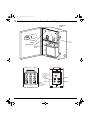
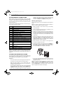
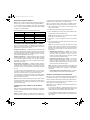
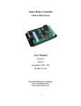
Please read before using this equipment. 49-454.fm Page 1 Wednesday, January 17, 2001 10:37 AM Two-Zone Burglar Alarm System Owner’s Manual 49-454.fm Page 2 Wednesday, January 17, 2001 10:37 AM Features Your RadioShack Two-Zone Burglar Alarm System provides the frame for a sophisticated perimeter alarm system. When properly installed, it warns you of unauthorized entry into your office or home. Its professional features make it compatible with most intrusion sensors and alarms. You can enhance your system by connecting additional security devices, such as sirens, lights, and other accessories. It can even initiate an optional telephone dialer that automatically calls specified phone numbers when the alarm is activated. Your local RadioShack store carries a full line of ULlisted security accessories. SUPPLIED ITEMS • • • • 1 remote keypad 2 keypad mounting screws 1 AC adapter 1 alarm center REQUIRED/OPTIONAL ACCESSORIES Your alarm system requires the following recommended accessories, available at your local RadioShack store. • 1 UL-listed alarm siren and/or strobe light Your alarm system’s features include: • 1 or more UL-listed sensors Delayed and Instant Alarm Zones — let you install sensors (not supplied) to create delayed and instant alarm zones. You can install loops of NO (normally open) and NC (normally closed) sensors in separate groupings within these zones. Panic/Tamper Zones — lets you install sensors, such as panic buttons and tamper switches (not supplied), to form a panic/tamper alarm zone, so you can sound the alarm any time, even if the alarm system is not armed. Battery Backup — lets you connect one rechargeable battery (not supplied) to provide power if AC power fails, to maintain all system settings. Automatic and Manual Battery Test — automatically checks the battery every 3 hours 50 minutes. You can also manually test the battery by pressing a button on the alarm center. WARNING: To reduce the risk of fire or shock hazard, do not expose this product to rain or moisture. ! • 1 or more single-gang electrical boxes and ground wire (14-gauge or larger), available at your local hardware store Any sensors and other items you purchase to enhance your system might require accessories not listed here. Make sure you have everything you need before installing your system. To help avoid false alarms while you install and test the alarm system, we recommend you use a lamp to temporarily connect to the alarm output terminals, so you can see it light instead of sounding the alarm. IMPORTANT NOTES • This product is UL-listed under standard 1023 – Household Burglar Alarm System Units. • This alarm system is not designed for use as a fire alarm. CAUTION: TO REDUCE THE RISK OF ELECTRIC SHOCK, DO NOT REMOVE COVER OR BACK. NO USER-SERVICEABLE PARTS INSIDE. REFER SERVICING TO QUALIFIED PERSONNEL. This symbol is intended to alert you to the presence of uninsulated dangerous voltage within the product’s enclosure that might be of sufficient magnitude to constitute a risk of electric shock. Do not open the product’s case. ! • 4-connector phone wire • Use only UL 1023-listed accessories with this alarm system. CAUTION RISK OF ELECTRIC SHOCK. DO NOT OPEN. • 1 rechargeable 12-volt battery such as RadioShack Cat. No. 960-0460 (available at your local RadioShack store) This symbol is intended to inform you that important operating and maintenance instructions are included in the literature accompanying this product. Some insurance companies give a discount for homes protected by a properly installed security system. Check with your insurance carrier about the requirements for such a discount. Home security systems require a permit in some areas. Check with your local police department before you install your system. This system provides Grade B service, which does not supervise the sensors to check for proper connection. To ensure complete protection, you should test the complete system, including each connected sensor and device, once per week with the supplied AC adapter disconnected from the alarm center. For more information, see “Weekly System Check” on Page 18. © 2001 RadioShack Corporation. All Rights Reserved. RadioShack and RadioShack.com are trademarks used by RadioShack Corporation. 2 Features 49-454.fm Page 3 Wednesday, January 17, 2001 10:37 AM A Quick Look at Your Alarm Center/Keypad PASSWORD RESET AC Indicator SYSTEM RESET BATT Indicator DELAY TIME ADJ BATTERY TEST DIP Switches (see “Setting the Keypad’s Address” on Page 13) DATA1 POWER GND DATA2 ANNC (see “Using Annunciate Mode” on Page 17) A Quick Look at Your Alarm Center/Keypad 3 49-454.fm Page 4 Wednesday, January 17, 2001 10:37 AM Preparation UNDERSTANDING THE SYSTEM homes or offices are alike, this system allows you the flexibility to design your security system to meet your individual needs. Your installed alarm system is designed to: • discourage potential intruders • scare intruders away before they take your property or harm you or others • alert you or others if someone breaks into your home The alarm center is the main control panel for the alarm system. It includes battery and AC power indicators, connections for sensors and other security devices, battery connection wires, entry and exit delay controls, and a battery test button. To use the system, you must install sensors and other security equipment in your home or office and connect them to the alarm center. Then, if a sensor signals the alarm center that its zone has been activated, the alarm center causes an attached alarm device (such as an alarm siren) to sound. Note: A sensor installed in the panic/tamper zone can activate an alarm, even if the alarm system is not armed. UNDERSTANDING ZONES A zone is a single area of coverage, such as a front door, a basement window, an entire room, or an entire home or office. Each zone is protected by one or more sensors (such as a door/window sensor, motion detector, or panic button). You can install as many sensors as you need. Depending on the type of sensor you use and the settings on the alarm center, you can set up the following types of zones: • Delayed zone — When the alarm system is armed and a sensor in a delayed zone is activated, the system waits for a preset period before sounding the alarm. This gives you time to open an entry door, walk to a remote keypad inside your home, and disarm the system before it sounds the alarm. • Instant zone — When the alarm system is armed and a sensor in an instant zone is activated, the system sounds the alarm immediately. • Panic/Tamper zone — When a sensor in a panic/tamper zone is activated (or when you press the panic button), the alarm system sounds the alarm immediately, even if the system is not armed. Proper planning will help you identify your security needs and additional items you must install to meet those needs. • Check your local and state regulations and ordinances with respect to installing and using home security systems. Be sure to secure any required permits before you continue. • Become knowledgeable about the different types of sensors and security devices you can use with your alarm system. Learn how the devices work before you decide to purchase and install them. This manual cannot explain every possible sensing device and application. Carefully read any instructions provided with the devices you purchase. Some devices and products mentioned in this manual are not available from your local RadioShack store. We recommend that you check stores that sell security equipment if you plan to install security devices that are not available from your local RadioShack store. RadioShack is not responsible for defects and errors in other manufacturers’ products, and assumes no liability for damage to other products or to the alarm system if these products are connected to the alarm system. Floor Plan Before you start to install your alarm system, we recommend that you make a security plan for your home. Even if you only plan to install a minimal system, take the time to plan a complete one. This will help you if you later decide to expand your security system. Plan to hide the system’s wiring, not only for cosmetic reasons, but to improve the security and effectiveness of the system. Also, plan to place outside alarm sirens and lights in high locations, out of reach under normal circumstances. This increases the range of the devices and helps prevent tampering. 1. Create a basic floor plan including the following information about each room inside and all areas outside of your home or office: • Room name Note: As you plan your alarm system, determine the locations in your home or office you want to protect, then install sensors to protect the zones you set up (see “Planning Your Security System”). • Interior and exterior walls PLANNING YOUR SECURITY SYSTEM • Planned location of outside alarm sirens and/or lights Your alarm system is designed to be the base on which you build a security system for your home or office. Since no two • Measurements of all rooms and interior/exterior walls 4 Preparation • Location of all openings (doors and windows) • Location of each AC outlet and telephone jack • Where you plan to install the alarm center 49-454.fm Page 5 Wednesday, January 17, 2001 10:37 AM two sensors and ending at the location where you want to install the alarm center. 2. After you complete the basic floor plan, make three copies of it. Label each copy as being the plan for one of the three zone types (instant, delayed, and panic/tamper). 3. Decide what sensors and other parts you want to install and where, and mark them on the appropriate floor plan. Then draw a line connecting the sensors you want to assign to the labeled zone type on each copy. This will show how the sensors will be wired to each other and the alarm center. For example, if you want to install a panic button in the bedroom and a tamper switch on a wall safe, on the Panic/Tamper floor plan, draw a loop connecting those When you finish, these drawings will show the layout of each zone and the location of each sensor assigned to that zone. Note: Since a violation of the panic/tamper zone immediately sounds the alarm (even if the system is not armed), do not assign sensors protecting doors and windows to the panic/ tamper zone. The different illustrations below show possible layouts for a home security system. Your floor plan will probably differ. Instant Zone Delayed Zone Kitchen BR1 Bath Kitchen BR1 Bath Dining BR2 Dining BR2 LR LR Garage Garage BR3 Alarm Siren BR3 Exterior Strobe Alarm Siren Alarm Center Telephone Jack Exterior Strobe Alarm Center Telephone Jack Panic/Tamper Zone AC Outlet AC Outlet Kitchen BR1 Tamper Switches Panic Buttons Bath Dining BR2 LR Garage BR3 Telephone Jack AC Outlet Alarm Siren Exterior Strobe Preparation Alarm Center 5 49-454.fm Page 6 Wednesday, January 17, 2001 10:37 AM System Planning Worksheet • Number and type of doors and/or entrances to area Use the system planning worksheet shown to help you determine what sensors and components you will need to equip your alarm system. Using your floor plans as a guide, fill out the system planning worksheet with the following information. • Number and type of windows in area • Name of room or area Room/Area 6 Door • Type and number of sensors needed to protect each location • Type of alarm siren, sounding device, and lighting device required Window Sensor Preparation Sounder Other 49-454.fm Page 7 Wednesday, January 17, 2001 10:37 AM Making a Shopping List When you complete your floor plan and system planning worksheet, use them to prepare a shopping list of the items you need to complete your system. Notes: • Before you actually purchase any items on your shopping list, read through the rest of this manual. Depending on your installation, later sections might contain additional information you need to select the proper items. • Refer to your floor plans to determine how much hookup wire you need to connect all sensors and security devices to the alarm center. Safeguarding Planning Records After you plan your system and purchase all the items you need, don’t forget to store all drawings, worksheets, receipts, and other documents in a secure place. Don’t throw them in the trash where a potential intruder might find them. OTHER WAYS TO IMPROVE SECURITY Securing Your Home or Office for its value. Once you complete your inventory, keep it in a safe place. You might also want to provide a copy to your insurance company. Label or mark your property. Apply warning decals. You can apply warning decals to the back of TV sets, stereo equipment, your personal computer and its peripherals, and other large, valuable items. Since items you might keep outside your home, such as power tools, air compressors, and lawn equipment, are also targeted by thieves, don’t forget to label those items, too. Note: Many agencies that produce warning decals also print a toll-free telephone number or identification number on them that you can use to find out if stolen property has been recovered. Use an ultraviolet marking pen. Invisibly mark smaller valuables with personal information, such as your driver’s license number or Social Security number. Although you (or a thief) can’t see the ink on the object, it appears brightly under ultraviolet light. Items you should mark include cameras, bicycles, hand tools, firearms, musical instruments, and art objects. Note: For more information about obtaining warning decals and marking pens, contact your local police department or stores that sell security equipment. Although your alarm system can function as a detection device and a deterrent, it does not physically keep intruders out. You should also consider the following ways to help protect your home or office. 1. Install sturdy locks on doors and windows. 2. Make sure that your home or office looks occupied when you are away. Steps you can take to accomplish this include: • connecting lights to cycled timers • keeping your lawn mowed and your property maintained • having mail and newspapers picked up regularly or cancelled while you are away 3. Organize or join a Neighborhood Watch association. 4. Put warning stickers on doors and windows to show potential intruders that your home is protected by a security system. Check your local police department for information on other measures you can take to ensure the security of your home. Protecting Personal Property In addition to protecting the boundaries of your home or office, you should also consider the following ways to help protect its contents. Inventory your property. Make a complete inventory of your personal property. Then, if your property is stolen, your police department and/or insurance company can use the information to help recover the property and/or reimburse you Preparation 7 49-454.fm Page 8 Wednesday, January 17, 2001 10:37 AM Property Inventory List Make as many copies as you need. Number 8 Item Model Serial No. Preparation Value Insured (Y/N) Where/How Marked 49-454.fm Page 9 Wednesday, January 17, 2001 10:37 AM SETTING UP THE SYSTEM Your system comes complete with the alarm center and one remote keypad. You must set up the alarm center before you add sensors and other components to the system. 1. Place the supplied template on the wall at the selected location. Then mark the positions for all four mounting screws. 2. In each marked location, drill a hole slightly smaller than the screw. Choosing a Location for the Alarm Center The supplied alarm center controls your alarm system’s functions and is the main connection point for all sensors, other connected devices, and power. Because no two homes are the same, we can only provide the following guidelines for choosing a mounting location for the alarm center. • Mount the alarm center where it cannot be easily seen by an intruder or casual visitor (for example, in a closet or pantry). Caution: Be careful not to drill into any wiring or objects behind the wall. Be sure to use the proper type of screw (molly bolt or anchors) if you do not mount the panel on wall studs. 3. Insert the screws into the wall, letting each head extend 3 /16 inch from the wall. 4. Use a flat-blade screwdriver to snap off the knock-out plug on the back of the alarm center to expose the tamper switch. Note: To prevent interference with the tamper switch, you must completely remove the knock-out plug. • Mount the alarm keypad where you can quickly access it after you enter your home. • Never mount the alarm center in a garage, basement, attic, or other location where it will be subjected to temperature and humidity extremes. • Mount the alarm center near an AC outlet that is not controlled by a wall switch. • If you plan to connect an automatic telephone dialer to your alarm system, mount the alarm center near a telephone jack. • To make installing hookup wire easier, mount the alarm center in a location central to the doors, windows, and rooms you plan to protect. Using the Tamper Switches There are two tamper switches built into the alarm center. One switch is inside the front of the alarm center above the fuse. This switch is designed to sound the alarm if an intruder attempts to open the front of the alarm center. The other switch is covered by a plastic knock-out plug on the back of the alarm center on the upper right side. This switch is designed to sound the alarm if an intruder attempts to remove the alarm center from its mounting location. Mounting the Alarm Center To install the alarm center, you need four screws (not supplied) with heads that fit into the keyhole slots on the back of the alarm center. Tamper Switch 5. Align the keyhole slots on the back of the alarm center with the screw heads in the wall, then carefully push the alarm center onto the screw heads and slide it down. 6. Use a flat-blade screwdriver to open the alarm center’s door, then use a screwdriver to tighten the mounting screws to secure it. Installing Battery Backup The alarm center’s backup battery powers the alarm system during an AC power failure. When AC power is restored, the alarm center automatically recharges the battery. You need one rechargeable 12-volt 4 AH lead acid battery to power the alarm center during an AC power failure. For the best performance and longest life, we recommend a RadioShack battery. Warning: Do not connect the battery to the alarm center yet. You will connect it while testing the alarm system. Cautions: • Use only the recommended battery in the alarm center. • The recommended battery contains high current when charged. Do not short-circuit its positive (+) and negative (–) terminals with any metal object. Avoid casual handling. • If the AC adapter is connected to the alarm center, unplug it from the AC outlet before installing or replacing the battery. To install the backup battery, simply slide the battery inside the alarm center. Preparation 9 49-454.fm Page 10 Wednesday, January 17, 2001 10:37 AM Normally-Open Sensors — stop electricity from flowing when not activated. When activated, a normally-open sensor completes the electrical path and signals the alarm center to sound the alarm. Normally-Closed Sensors — allow electricity to flow when not activated. When activated, normally-closed sensors break the electrical path and signal the alarm center to sound the alarm. Battery Notes: Choosing a Location for the Remote Keypad The remote keypad supplied with your alarm system lets you arm and disarm the system, change the system’s operation, and see status information about the system. You can also purchase up to three additional keypads to use with your alarm system. • Mount the remote keypads in a location where all family members who will use them can reach them. • For many installations, it is best to mount the remote keypads near the main entry of your home. • The remote keypad supplied with your alarm system is not weatherproof. Do not install it in a location where it will be exposed to excessive moisture. • The remote keypads should not be mounted in a location where they are exposed to temperatures outside the range of 32–122° F. CHOOSING THE COMPONENTS Sensors Sensors are the eyes and ears of your alarm system. When activated, they send a signal to your alarm center that activates the alarm. Your local RadioShack store carries a full line of sensors. Sensors are usually classified into two types: Perimeter Sensors — These sensors protect areas such as doors and windows. Types of perimeter sensors include door and window contacts, window foil, glass-breakage detectors, and infrared photorelays. Area Sensors — Types of area sensors include ultrasonic and infrared motion detectors, vibration detectors, and panic buttons and tamper switches. You can place area sensors such as motion detectors in wide areas such as your living room, or in access areas such as halls. You can place panic buttons just about anywhere. Decide which entrances or areas an intruder would be most likely to use, and place sensors at those entrances or areas first. The sensors you can connect to the alarm system should be either normally-open (NO) or normally-closed (NC) for the Delay Zone and Instant Zone, but only normally-open for the Panic/Tamper Zone. 10 • You cannot mix normally-open and normally-closed sensors within one loop. • Normally-closed sensors are considered more secure than normally-open sensors. • Unless otherwise noted, you need two-conductor hookup wire to connect the sensors to the alarm center. • Refer to your RadioShack catalog for specific types and catalog numbers of each sensor listed here. The most common types of sensors are: Magnet Switches — Magnet switches are available in both normally-open and normally-closed types. When mounted, a magnet switch either opens or closes when the object it is attached to is moved, signaling the alarm center to sound the alarm. You can use magnet switches for doors, windows, or anywhere you want the alarm to sound when something is moved. Plunger (Contact) Switches — Plunger switches are available in both normally-open and normally-closed types. You can install a plunger switch inside a door frame on the side with the hinges. This type of switch cannot be seen when the door is closed. You can use plunger switches for doors, windows, or any where you want the alarm to sound when something is opened or moved. Metallic Foil Tape — Metallic foil tape is a normally-closed type of sensor. Install metallic foil tape on the glass just inside the outer frame of windows that are not movable, such as plate glass or glass inserts in doors. If the glass is broken, the tape also breaks and signals the alarm center to sound the alarm. Mount metallic foil tape around the perimeter of the glass, then connect it to a normally-closed circuit. Vibration Detectors — Vibration detectors are available in both normally-open and normally-closed types. When these sensors detect vibration on any surface, they signal the alarm center to sound the alarm. Glass Breakage Detectors — Glass breakage detectors are a type of vibration detector and are available in both normally-open and normally-closed types. You attach a glass breakage detector near a window. If the window is broken or struck, the glass breakage detector signals the alarm center to sound the alarm. Motion Detectors — The most common types of motion detectors are: • Ultrasonic — Send out an inaudible high-frequency sound, which bounces off objects in the protected area and returns to the sensor. When an object moves in the Preparation 49-454.fm Page 11 Wednesday, January 17, 2001 10:37 AM protected area, the pattern of the sound waves changes, signaling the alarm center to sound the alarm. • Infrared — Work like ultrasonic motion detectors, except that they use invisible infrared light instead of high-frequency sound to detect motion. • Microwave — Work like ultrasonic motion detectors, except that they use radio waves instead of high-frequency sound to detect motion. Some motion detectors have a built-in alarm sounder and can be connected directly to an alarm siren or other sounding device. If the type of motion detector you select has tamper protection, you might need six-conductor hook-up wire to connect it to the alarm center. Otherwise, you need four-conductor hook-up wire to connect motion detectors. Panic Buttons and Tamper Switches — Are normallyopen types of sensors. A panic button lets you sound the alarm at any time, even if the alarm center is not armed. A tamper switch instantly sounds the alarm if someone tries to open the secured object. You can mount these switches on the alarm center, a gun cabinet, or anywhere you want the alarm to instantly sound if you press the switch or someone tampers with it. Sirens and Lights Pre-Alarm Buzzer — When the alarm system is armed and a delayed zone is activated, the alarm center activates a pre-alarm for the amount of time you set (see “Setting the Entry and Exit Delay” on Page 17). After that delay time elapses, the alarm system sounds the alarm siren and other connected security equipment. When the battery is low, the pre-alarm sounds for 5 seconds per minute. To hear the prealarm, you must connect a small sounding device such as a piezo buzzer to the alarm center. Mount the device where you can hear it during the entry delay. Do not mount it on or near the alarm center. The sound might lead an intruder to find the alarm center and possible disable the systems. When deciding where to install a security strobe, choose a location outside your home where the strobe’s light is highly visible. Automatic Telephone Dialer For a higher level of security, you can connect an automatic telephone dialer to your alarm system. We recommend RadioShack Cat. No. 49-434 (available at your local RadioShack store). An automatic telephone dialer connects to your phone line and automatically calls one or more preset phone numbers if the alarm sounds. Note: Many automatic telephone dialers can use the alarm system’s battery power to dial numbers if AC power is disconnected. When deciding where to install an automatic telephone dialer, select a location that is: • Near a phone jack • Near an AC outlet • Not easily accessible to an intruder Cautions: • If you connect an automatic telephone dialer to your system and want to program it to call your local police department, check with them first. Some police departments do not accept calls from automatic telephone dialers. If your police department does not accept calls from automatic dialing equipment, you can program it to call a friend or private security service who can notify the police department, if necessary. • Some automatic telephone dialers deliver a prerecorded voice message to the desired number when activated, while others transmit an electronic signal to a private security service. In most cases, private security services charge a fee to accept calls from automatic dialing equipment. For more information, call the police department and private security services in your area. Alarm Siren — When a sensor is activated and the system is armed (or the panic/tamper zone is violated), the system can activate an alarm siren connected to the alarm center. Mount the siren outside your home where you, your neighbors, and the police can hear it. If you mount it in an area that is not protected by the alarm system (such as an outside eave), mount it inside a siren enclosure to discourage tampering. Security Strobe — When a sensor is activated and the system is armed (or the panic/tamper zone is violated), the system can activate a security strobe or other types of lights connected to the alarm center. Note: You can connect a security strobe to the same outputs on the alarm center as you use for the alarm siren. For more information, see “Connecting a Siren and/or Lights” on Page 14. Preparation 11 49-454.fm Page 12 Wednesday, January 17, 2001 10:37 AM Installation SYSTEM WIRING CONNECTIONS Many sensors come with instructions to help you install them. Follow the instructions (if provided) with each sensor to install it in the location you noted in your floor plan. Then mount the alarm center and connect the sensors and other security devices to it. Use this chart and the following sections to connect the system’s wiring to the alarm center. Terminal Function 1 Delayed Zone Loop — Normally-Open 2 Delayed Zone Loop — Normally-Closed 3 Common (Ground) 4 Instant Zone Loop — Normally-Closed 5 Instant Zone Loop — Normally-Open 6 Panic/Tamper Zone — Normally-Open 7 Remote Keypad — GND 8 Remote Keypad — DATA2 9 Remote Keypad — POWER 10 Remote Keypad — DATA1 11 Alarm Relay contact — +24 VDC 1A Max. 12 Alarm Relay contact — +24 VDC 1A Max. 13 Pre-alarm negative (–) — 8 to 18 VDC 50 mA Max. 14 Pre-alarm positive (+) — 8 to 18 VDC 50 mA max. 15 Alarm Siren/Light negative (–) — 10 to 18 VDC 1A Max. 16 Alarm Siren/Light positive (+) — 10 to 18 VDC 1A Max. 17 Security Dialer 18 AC Adapter — 12 VAC 30VA 19 AC Adapter — 12 VAC 30VA keypad is interrupted when the system is disarmed, the pre-alarm sounds for 5 seconds, the alarm sounds for 4 minutes, and READY and ARMED alternately flash. Mounting the Keypad Follow these steps to mount the supplied remote keypad on a wall. Note: You need 4-connector phone wire (not supplied) to connect remote keypads to the alarm system. 1. Select a location on the wall next to (but not directly over) a wall stud. 2. Using a single-gang electrical box as a template, cut a hole in the wall the size of the box. 3. Route the connection wires for the remote keypad from the alarm center through the hole. Be sure to label each wire to be connected to the remote keypad, and leave enough slack in the wires so you can attach them to the keypad later. 4. Insert the electrical box into the hole, then secure it to the wall by nailing it to the nearby wall stud, or using metal strips designed for mounting an electrical box in wallboard. Make sure the electrical box is recessed slightly below the surface of the wall. 5. Press the button on the bottom of the keypad, then remove the keypad’s front cover. 6. Connect the wires to the keypad. Connect POWER on the keypad to Terminal 9 on the alarm center, GND on the keypad to Terminal 7, DATA1 on the keypad to Terminal 10, and DATA2 on the keypad to Terminal 8. Note: You can power a remote security device by connecting it to Terminals 14 and 15. For more information, see “Connecting and Powering a Remote Security Device” on Page 14. CONNECTING REMOTE KEYPADS You must connect at least the supplied remote keypad to the alarm system to arm and disarm it. You can connect up to three additional remote keypads, in any combination. Important: • You must connect each remote keypad to the alarm center before you connect power to the alarm system. • When the alarm system is on, the alarm center constantly confirms that each keypad is still connected to the system, and vice versa. 7. Use the two supplied keypad mounting screws to secure the keypad inside the electrical box. Then replace the keypad’s front cover. Note: If a keypad is disconnected from the alarm center while the system is armed, ARMED flashes and the alarm sounds. Reconnect the keypad to the alarm center and press SYSTEM RESET on the alarm center. Then you can use the keypad with the alarm center again. • If the connection between the alarm center and keypad is interrupted when the system is armed, READY and ARMED alternately flash and the alarm sounds for 4 minutes. If the connection between the alarm center and 12 Installation 49-454.fm Page 13 Wednesday, January 17, 2001 10:37 AM Setting the Keypad’s Address of each loop’s wire pair with its zone type and if the connected sensors are normally-open or normally-closed. Note: If you connect only the supplied remote keypad to the alarm center, you do not need to set the keypad’s address. After you route the wires for each loop to the alarm center, follow these steps to connect the wires to the alarm center. If you connect remote keypad(s) other than the supplied one, you must set the switches on the back of each keypad to assign it a unique address. 1. Use a screwdriver to knock off one of the plugs on the alarm center’s case. Set the switches for each remote keypad as follows: 2. Route each loop’s wires through the plug’s hole. Keypad Number Address 1 Address 2 1 Off Off 2 On Off 3 Off On 4 On On 3. Use a screwdriver to remove the jumpers between Terminals 2 and 3 and Terminals 3 and 4. Note: Save these jumpers. You might have to re-install them after you connect the loops. 4. Strip about 1/4 inch of insulation from the end of each wire. CONNECTING SENSORS INTO LOOPS 5. Use a screwdriver to connect each loop’s wires to the alarm center as follows. Note: Do not connect more than two wires to a single terminal. If there are more than two wires to connect to a terminal, first connect the wires to an external barrier strip, then connect a single wire from the barrier strip to the terminal. After you install all sensors in the locations you noted in your floor plan, you can connect your alarm system’s sensors together into the three types of loops. Delayed Loop (Zone) — Causes the alarm center to sound the alarm after a preset period of time when a sensor with the loop is activated, if the alarm system is armed. You can have separate groupings of normally-open and normallyclosed sensors within this type of loop. • Delayed Zone (Terminals 1, 2, and 3) — If you connected normally-open sensors to this loop, connect the loop’s wires to Terminals 1 and 3. If you connected normally-closed sensors to this loop, connect the loop’s wires to Terminals 2 and 3. Instant Loop (Zone) — Causes the alarm center to sound the alarm instantly when a sensor within the loop is activated, if the alarm system is armed. You can have separate groupings of normally open and normally-closed sensors within this type of loop. • Instant Zone (Terminals 3, 4, and 5) — If you connected normally-open sensors to this loop, connect the loop’s wires to Terminals 5 and 3. If you connected normally-closed sensors to this loop, connect the loop’s wires to Terminals 4 and 3. Panic/Tamper Loop (Zone) — Causes the alarm center to sound the alarm instantly when a sensor within the loop is activated, even if the alarm system is not armed. You can only have a group of normally-open sensors within this type of loop. Note: Terminal 3 provides grounding for the Instant and Delayed Zone’s loops. One wire of both normally-open and normally-closed loops of sensors is connected to Terminal 3. To make a loop of normally-closed sensors, you must connect them in series. This means you cut one of the conductors and connect the sensor in line with that conductor. To make a loop of normally-open sensors, you must connect them in parallel. This means you connect both conductors to each sensor along the loop. Note: When you connect sensors to the loops, make sure all of the sensors within each group are either normally-open or normally-closed. You cannot mix different types of sensors within the same group. • Panic/Tamper Zone (Terminals 6 and 7) — Connect the panic/tamper loop’s wires to Terminals 6 and 7. Jumpers on Normally-Closed Terminals Both of your alarm center’s normally-closed loops must have a complete circuit (one of the supplied metal jumpers or a loop of normally-closed sensors) before the system will arm. Your alarm center comes with two metal jumpers for your alarm system’s normally-closed loops. Depending on your installation, follow these instructions to install the jumpers. Connecting Loops of Sensors to the Alarm Center After you have connected all sensors noted in your floor plan in loops, route the ends of each loop of sensors to the alarm center’s location. Note: To make it easier to connect the loops of sensors to the alarm center, use tape you can write on to mark the end • If you did not install any normally-closed loops of sensors, install one jumper between Terminals 2 and 3, then install the other jumper between Terminals 3 and 4. • If you installed a normally-closed loop of sensors only in the Delayed Zone, install a jumper only between Terminals 3 and 4. Installation 13 49-454.fm Page 14 Wednesday, January 17, 2001 10:37 AM • If you installed a normally-closed loop of sensors only in the Instant Zone, install a jumper only between Terminals 2 and 3. CONNECTING A SIREN AND/OR LIGHTS • If you installed normally-closed loops of sensors both in the Instant and Delayed Zones, do not connect any jumpers. You can connect an alarm siren and security strobe or other light to Terminals 15 and 16 on the alarm center. When the alarm system sounds the alarm, it activates the alarm siren and light. CONNECTING A PRE-ALARM BUZZER Caution: You must use a pre-alarm buzzer that uses 12 volts and is rated at 50 mA or less. Using a pre-alarm buzzer that does not meet these specifications could damage the alarm center or the pre-alarm buzzer. Connect the pre-alarm buzzer’s negative (–) wire to Terminal 13, then connect the pre-alarm buzzer’s positive (+) wire to Terminal 14. CONNECTING AND POWERING A REMOTE SECURITY DEVICE You can power a remote security device by connecting it to Terminals 14 and 15 on the alarm center. Caution: You must use a remote security device that uses 12 volts and is rated at 750 mA or less. Using a device that does not meet these specifications could damage the alarm center or the device. Note: The voltage supplied from Terminals 14 and 15 varies from 10 to 18V DC, depending on the AC voltage, battery voltage, and the amount of accessory power being used. Connect the device’s negative (–) wire to Terminal 15, then connect the device’s positive (+) wire to Terminal 14. Warning: Do not connect the alarm siren and/or light to the alarm center yet. You will connect them while testing the alarm system. Caution: If you connect both an alarm siren and light to the alarm center, they must be connected in parallel and the combined rating of both devices must be 1A or less. Using a siren and light together that do not meet this specification could damage the alarm center, siren, and light. Note: When you test the system, we recommend you connect a test lamp to the alarm center instead of the alarm siren and/or light. This lamp will let you see if the alarm siren and/or light will work properly during the test without producing a false alarm. We explain this in detail in “Completing and Testing the Installation”. CONNECTING AC POWER Use a screwdriver to attach 14-gauge hookup wire to both terminals on the back of the AC adapter, then connect one wire to Terminal 18 and the other wire to Terminal 19 on the alarm center. It does not matter which wire you connect to Terminal 18 or Terminal 19. Warning: Do not plug the AC adapter into the AC outlet yet. You will plug it in while testing the alarm system. Note: Make sure the AC outlet you use is not controlled by a wall switch. Connecting a Remote Security Device to the Alarm Relay Contact Switch COMPLETING AND TESTING THE INSTALLATION Notes: • Terminals 11 and 12 do not provide power to the device. They simply turn it on or off. • The device you use must have contact switch connections that cause the device to trigger when the alarm center contact switch closes. Connect the device’s switch connections to Terminal 11 and Terminal 12. Now you can finish installing your alarm system and test it to be sure that it works. This will also help you understand its operation. Important: For proper operation, make sure the alarm center’s door is closed before plugging in the AC adapter. Cautions: • Always notify local authorities, your neighbors, and other people in your home or office before you test your alarm system. In some areas, testing any part of your alarm system might be considered a false alarm, which might be illegal in your area. Check the regulations in your area. • If you connected an automatic telephone dialer to the alarm center, notify the people and/or security company whose numbers the device will call and get their prior consent before you test your alarm system. Some security companies charge a fee for test calls. 1. Double-check all steps in “Installation” on Page 12 to make sure you connected everything correctly. 14 Installation 49-454.fm Page 15 Wednesday, January 17, 2001 10:37 AM If READY is still off, check the loops as follows: 2. Connect a test lamp to Terminals 15 and 16 on the alarm center. This lamp lets you see if the alarm siren and/or security strobe will work. • Normally-Open Loops — Disconnect the wires from Terminals 1 and 5. If READY lights, one of the normally open loops (either in the Instant Zone or Delayed Zone) is not wired correctly. Reconnect the wires for each group in each loop separately to determine which loop is not wired correctly. Caution: You must use a lamp that uses 12 volts and is rated at 1A or less. Using a lamp that does not meet these specifications could damage the alarm center or the lamp. • Normally-Closed Loops — Connect a short piece of wire between Terminals 2 and 3, then connect another between Terminals 3 and 4. If READY lights, one of the normally closed loops (either in the Instant Zone or Delayed Zone) is not wired correctly. 3. Plug the AC adapter into a standard AC outlet. Caution: To prevent electric shock or fire hazard, use only the supplied AC adapter to power the alarm center. ARMED on the keypad and AC on the alarm center light, BATT and READY flash to indicate an exit delay (since the alarm system is in the process of arming). If they light or flash, go to Step 4. If the indicators do not light or flash, unplug the AC adapter and make sure: 7. Arm the alarm center by using any connected keypad to enter the password (1234 is the default password) then press ARM once, or simply press ARM twice. Make sure ARMED on the keypad is on. Note: You cannot arm the alarm center if any loops remain activated. If any of the loops were activated when the alarm system was turned on, ARMED will be off, indicating that the alarm center did not arm because of the loop violation. • The fuse inside the alarm center is not blown. If it is, replace it (see “Replacing the Fuse” on Page 19) and repeat this step. • The AC adapter’s wires are connected correctly to Terminals 18 and 19. If they are not, connect them correctly (see “Connecting AC Power” on Page 14) and repeat this step. 8. Check the loops installed in the Delayed Zone. Turn DELAY TIME ADJ to 55, then set off any sensor installed in the Delayed Zone. • The AC outlet has AC power. If it does not, restore AC power and repeat this step. The pre-alarm sounder connected to Terminals 13 and 14 begins to sound and continues sounding for 55 seconds during the entry delay time. ARMED starts blinking. • RESET on the AC adapter is not popped out (indicating an overload). If it is, correct the overload, press RESET completely back inside the AC adapter (see “Resetting the AC Adapter’s Circuit Breaker”), and repeat this step. After the entry delay time expires, the lamp you connected to Terminals 15 and 16 (alarm siren and light) lights for 4 minutes. Disarm the alarm system by entering 1 2 3 4 (the default password) then pressing CANCEL on a keypad until ARMED stops blinking. 4. Unplug the AC adapter. 5. If you installed the backup battery, connect the black battery lead inside the alarm center to the battery’s negative (–) terminal, then connect the red battery lead to the positive (+) terminal. Caution: Make sure the battery is connected correctly inside the alarm center. Improper installation might cause the fuse inside the alarm center to blow, prevent the alarm system from operating during an AC power failure, and damage the battery and the alarm system. Reset the sensor you set off above. READY lights. 9. Press ARM twice so ARMED lights. 10. Check the loops installed in the Instant Zone. Set off any sensor installed in the Instant Zone. READY turns off, ARMED blinks, and the lamp you connected to Terminals 15 and 16 (alarm siren and light) lights for 4 minutes. Important: For proper operation, make sure the alarm center’s door is closed before plugging in the AC adapter. 6. Plug in the AC adapter. AC on the alarm center lights. READY flashes. If READY flashes, go to Step 8. Disarm the alarm system by entering 1 2 3 4, then pressing CANCEL on a keypad until ARMED stops blinking. Reset the sensor you set off. 11. Check the sensors installed in the Panic/Tamper Zone. If READY does not flash, one or more of the loops of sensors is not connected properly, or one or more of the sensors has been activated. Make sure all sensors are in their normal states (either normally open or normally closed) on the same loop. If they are not, connect them correctly (see “Connecting Sensors into Loops” on Page 13 and “Connecting Loops of Sensors to the Alarm Center” on Page 13). Installation Disarm the alarm system by entering 1 2 3 4, then set off any sensor installed in the Panic/Tamper Zone. READY turns off, the alarm center arms, ARMED blinks, and the lamp you connected to Terminals 15 and 16 (alarm siren and light) lights for 4 minutes. Reset the sensor you just set off, then disarm the alarm system by entering the password. 15 49-454.fm Page 16 Wednesday, January 17, 2001 10:37 AM Test the panic function of each installed remote keypad by holding down ENTER and CANCEL. The alarm center arms, ARMED blinks, and the lamp you connected to Terminals 15 and 16 (alarm siren and light) lights for 4 minutes. 12. Disarm the alarm system by entering 1 2 3 4, then hold down SETUP for 2 seconds. ARMED and READY flash slowly. Enter the password. ARMED and READY flash quickly. Press ANNC once. ARMED and READY turn off. To enter announce mode, press ENTER. READY flashes 3 times. To exit announce mode, press CANCEL. READY flashes 3 times. 13. Hold down BATT TEST on the alarm center for 2 seconds. If BATT on the alarm center does not light, the backup battery is OK. • The backup battery might have insufficient power. Check the battery connections. If the connections are OK, the battery will be automatically recharged. If it does not recharge, replace it promptly. 14. Arm the alarm system by entering 1 2 3 4, then pressing ARM. Then disarm by entering the duress code, 1 2 3 5. The security dialer is triggered. 15. Use a flat-blade screwdriver to remove the screw from the center of the AC outlet and discard the screw. Then attach the AC adapter to AC outlet using the attached screw to secure it and discourage tampering. 16. Disconnect the lamp from Terminals 15 and 16, then connect the alarm siren’s and/or light’s negative (–) wire(s) to Terminal 15 and connect the positive (+) wire(s) to Terminal 16. Your security system is ready to use! If BATT flashes: • Check the fuse on the alarm center. If it is blown, see “Replacing the Fuse” on Page 19 and repeat this step. Operation ARMING THE SYSTEM To arm the system, use any connected keypad to enter the password then press ARM once, or simply press ARM twice. If your alarm system was activated while it was armed and the alarm sounded, ARMED on the keypad flashes to show that the alarm had sounded. To stop the alarm, enter the password. To stop ARMED from flashing, press CANCEL. If you enter the correct password and there are no activated or faulted zones, ARMED on the keypad lights, and the alarm system is armed. If you enter the wrong password, the system does not arm. If your alarm system was activated and the alarm sounds, enter the duress code to disarm the system. The alarm stops, but the security dialer still sends the emergency message. To stop the security dialer, enter the password. Notes: If the system is armed, opening the front cabinet or taking the alarm center off the wall triggers the alarm. Make sure to disarm the system before you open the cabinet or remove the alarm center from the wall. • While entering the password, if you enter an incorrect digit before entering the last digit, you can press CANCEL to cancel your previous entries, then enter the password again. • When you use a connected keypad, all other keypads are locked out for 10 seconds after the last key press. DISARMING THE SYSTEM To disarm the system normally, use any connected keypad to enter the password while the system is armed. Note: When the system is in exit delay mode, press CAN- SOUNDING A PANIC ALARM You can activate the alarm system’s panic alarm at any time, even if the system is not armed. To sound a panic alarm, press any installed panic button (if you installed a panic/tamper zone) or press ENTER and CANCEL at the same time on any remote keypad. The alarm sounds and the system automatically arms. CEL to disarm the system. CHANGING THE PASSWORD If you enter the correct password, ARMED on the keypad turns off, and the alarm system is disarmed. If you enter the wrong password, the system remains armed, but gives no indication a wrong code was entered. Arm or disarm the alarm center by using the number keys on the remote keypad to enter a four-digit password you choose. The default password for the alarm center is 1234. Note: If you enter the wrong password three times in a row, the alarm center locks out all connected keypads for 5 minutes. This prevents an intruder from easily determining your password by trying random combinations. 16 Follow these steps to enter a new password. 1. If the alarm center is armed, use the keypad to enter the current password or 1 2 3 4 (the default password). The alarm center is disarmed. Operation 49-454.fm Page 17 Wednesday, January 17, 2001 10:37 AM 2. Hold down SETUP on the keypad until ARMED and READY slowly flash. 3. Within 30 seconds, enter the current password. If you entered the correct password, ARMED and READY flash quickly. 4. Enter a new password. ARMED and READY turn off. Enter the new password again to confirm. If the system accepts the password, READY flashes 3 times and the system returns to standby mode. If you entered an incorrect password, ARMED flashes 3 times and the system returns to standby mode. The duress code will be same as the password + 1 (i.e., if the password is 1579, the duress code is 1570. If the password is 1246, the duress code is 1247). Note: If you do not enter the correct password within 30 seconds in Steps 3 or 4, simply start again from Step 2. To restore the default password (1 2 3 4), press PASSWORD RESET on the alarm center. USING ANNUNCIATE MODE Annunciate mode lets you set the alarm system so it sounds a brief pre-alarm if it detects any change in the assigned zone. 1. If the system is disarmed and no zone is violated, hold down SETUP for about 2 seconds. ARMED and READY flash slowly. 2. Enter the current security code within 30 seconds. ARMED and READY flash rapidly. 3. Press ANNC (annunciate) once. ARMED and READY turn off. 4. To enable annunciate mode, press ENTER. READY flashes 3 times. If the alarm system detects any change in the assigned zone, it sounds a brief pre-alarm. To disable annunciate mode, press CANCEL. READY flashes 3 times. SETTING THE ENTRY AND EXIT DELAY DELAY TIME ADJ lets you adjust how long the alarm system waits before arming. If a sensor is activated in the Delayed Zone, then reset while the pre-alarm is sounding, the alarm will not sound. This gives you time to exit your home or office after arming the system. DELAY TIME ADJ also lets you adjust how long the alarm system waits before sounding the alarm, to give you time to disarm the system. During this period, the pre-alarm sounds. Notes: • The pre-alarm sounds when any sensor is activated in the Delayed Zone. Use the pre-alarm as a reminder to disarm the system. • Be sure to set DELAY TIME ADJ while the alarm center is disarmed. There are six delay options can be selected. Rotate DELAY TIME ADJ (10, 20, 30, 40, 50 or 55) to set the desired number of minutes. Note: The 50/55 second delay setting cannot be used for UL-recognized installation. SYSTEM RESET Press SYSTEM RESET to reset the password, alarm, and keypad. Testing the System TESTING THE BATTERY BATT Indicator Although the alarm center automatically tests the backup battery each time you arm and disarm the system and once every 3 hours and 50 minutes, you can also press BATT TEST on the alarm center to test the battery at any time. Test the backup battery at least once per week. Flashing rapidly BATT Indicator Meaning Lit AC power is low or off. Check the AC adapter and AC power Not lit The battery is fully charged. Flashing slowly The battery is low. The battery has insufficient power due to one or more of the following reasons: • No battery installed. • Faulty battery connection. Note: If you installed a new backup battery in the system, wait 24 hours for the alarm system to charge it before manually testing it. While the battery is charging, BATT flashes. When the battery is charged, BATT goes off. When you press BATT TEST, check BATT for the condition of the backup battery. Meaning • The fuse inside the alarm center is blown (see “Replacing the Fuse” on Page 19). • Battery is defective. Notes: • If the battery is low, defective or disconnected when the unit has AC power, the pre-alarm sounds for 5 seconds every minute. • Enter the password and press CANCEL to stop the prealarm. • After 3 hours 50 minutes, if the battery is still low or disconnected, the pre-alarm sounds again. Testing the System 17 49-454.fm Page 18 Wednesday, January 17, 2001 10:37 AM TESTING THE SIREN AND/OR LIGHTS WEEKLY SYSTEM CHECK Important: Always notify local authorities, your neighbors, and other people in your home or office before you test your alarm system. In some areas, testing any part of your alarm system might be considered a false alarm, which might be illegal in your area. Check your local regulations. Test your alarm system each week to be sure that it works. Hold down ENTER and CANCEL on the keypad at the same time to test the alarm siren and/or lights connected to Terminals 15 and 16. You should test these devices at least once a week. If the test lamp (see “Completing and Testing the Installation” on Page 14) or alarm/light does not work when you press ENTER and CANCEL, check the devices and their wiring. CHECKING THE INDICATORS READY on the remote keypad indicates the condition of the loops of sensors in all zones in the alarm system. READY is: Meaning No sensors are activated. Not lit One or more sensors in one or more loops has been activated. This might indicate that a door or window has been left open. • The entry or exit delay is in progress. • The system is in Setup mode. Note: If READY on the remote keypad is not lit, you must find the activated sensor and reset it before you can arm the alarm system. ARMED on the remote keypad indicates if the alarm center is armed and the arm status. ARMED is: The alarm system is armed. Not lit The alarm system is disarmed. Flashing • One of more sensors in one or more loops has been activated and caused an alarm. This might indicate that a door or window has been left open. • The system is in Setup mode. Note: When a sensor has been activated, ARMED continues to flash, even if the siren or light has stopped sounding, until you press CANCEL. AC on the alarm center indicates the status of the AC power being supplied to the alarm center. AC is: Meaning Lit AC power is normal. Flickering or off AC power is low (less than 95 VAC). 18 • Always notify local authorities, your neighbors, and other people in your home or office before you test your alarm system. In some areas, testing any part of your alarm system (if you do not follow Step 1) might be considered a false alarm, because the alarm will sound. This might be illegal in your area. Check your local regulations. • If you connected an automatic telephone dialer to the alarm center, notify the people and/or security company whose numbers the device will call and get their prior consent before you test your alarm system. Some security companies charge a fee for test calls. 2. Arm the system. ARMED on the keypad lights, and READY flashes. If READY flashes, go to Step 3. If READY does not flash, one or more sensors in the Instant and/or Delayed Zones is activated or faulty. Check each sensor in each zone and reset it until READY lights. 3. Check the sensors installed in the Panic/Tamper Zone. Disarm the system, then set off any sensor installed in the Panic/Tamper Zone. The alarm center arms, ARMED blinks, and the lamp you connected to Terminals 15 and 16 (alarm siren and light) lights for 4 minutes. Reset the sensor you just set off, then disarm the system. Meaning Lit • For proper operation, make sure the alarm center’s door is closed before plugging in the AC adapter. 1. Disarm the system, disconnect any alarm siren or light from Terminals 15 and 16 on the alarm center, then connect the test lamp to the terminals. Lit Flashing Important: Test the panic function of each installed remote keypad by holding down both ENTER and CANCEL on the keypad. The alarm center arms, ARMED blinks, and the lamp you connected to Terminals 15 and 16 (alarm siren and light) lights for 4 minutes. 4. Press BATT TEST on the alarm center. If BATT on the alarm center does not light, the backup battery is OK. If BATT flashes: • Check the fuse on the alarm center. If it is blown, see “Replacing the Fuse” on Page 19 and repeat this step. • The backup battery might have insufficient power. Check the battery connections. If the connections are OK, the battery will be automatically recharged. If it does not recharge, replace it promptly. 5. Disconnect the lamp from Terminals 15 and 16, then connect the alarm siren’s and/or light’s negative (–) wire(s) to Terminal 15 and connect the positive (+) wire(s) to Terminal 16. Testing the System 49-454.fm Page 19 Wednesday, January 17, 2001 10:37 AM Care To enjoy your RadioShack Two-Zone Burglar Alarm System for a long time: • Keep the alarm dry. If it gets wet, wipe it dry immediately. • Use and store the alarm only in normal temperature environments. • Handle the alarm gently and carefully. Do not drop it. RESETTING THE AC ADAPTER’S CIRCUIT BREAKER The AC adapter has a circuit breaker to protect itself from an overload. If an overload occurs, RESET pops out, the AC adapter stops supplying power, and AC POWER on the alarm center turns off. Warning: Before you reset the circuit breaker, unplug the AC adapter and disconnect the backup battery. • Keep the alarm away from dust and dirt. • Wipe the alarm with a damp cloth occasionally to keep it looking new. Modifying or tampering with the alarm’s internal components can cause a malfunction and might invalidate its warranty and void your FCC authorization to operate it. If your alarm is not performing as it should, take it to your local RadioShack store for assistance. Caution: Circuit breakers can trip for many reasons, including short circuits, power surges, and improper installation. Check your installation for a short circuit or improper installation and correct any problems you find. Then reconnect the battery and AC adapter and try to reset the AC adapter’s circuit breaker. If the circuit breaker fails to reset, contact your local RadioShack store. To reset the circuit breaker, press RESET back into the AC adapter until it stops. REPLACING THE FUSE If the alarm center does not operate, you might need to replace the fuse with a 3-amp fast-blow fuse, available at your local RadioShack store. Warning: Before you begin, unplug the AC adapter and disconnect the backup battery. Caution: Fuses can fail for many reasons, including short circuits, power surges, and improper installation. Check your installation for short circuits or improper installation and correct any problems you find. Then, if the spare fuse fails after you install it, contact your local RadioShack store. 1. While using a flat-blade screwdriver to press the slot on the upper right side of the alarm center’s cover and your thumb to press the oval on the lower right side of the cover, pull the cover out to open it. 2. Pull the ribbon inside the cover. The fuse pops out. 3. If the fuse is blown, replace it. Caution: Make sure you replace the fuse only with another fuse of the same type and rating. 4. Wrap the ribbon around the new fuse, then insert the fuse into the fuse holder. 5. Reconnect the battery. 6. Close the alarm center’s cover. 7. Reconnect the AC adapter. Care 19 49-454.fm Page 20 Wednesday, January 17, 2001 10:37 AM Specifications Exit and Entry Delay Control Time .......................................................................................................................... 10–55 seconds, adjustable Multiple Incorrect password Lockout Time ....................................................................................................................................... 5 minutes Program Mode Time-Out ................................................................................................................................................................ 30 seconds Key Press Lock Time ..................................................................................................................................................................... 10 seconds Automatic Alarm Reset Time ............................................................................................................................................................ 4 minutes Trigger Resistance: NC ............................................................................................................................. Loop will trigger alarm if resistance exceeds 500 Ohms NO ................................................................................................................... Loop will trigger alarm if resistance is less than 50,000 Ohms Loop Resistance: NC ........................................................................................................................................................................................... 500 Ohms Max. NO ....................................................................................................................................................................................... 50,000 Ohms Min. Power Consumption (Armed): (One Keypad Installed) ............................................................................................................................................................................. 12 W (One Keypad Installed and 750 mA Accessory Load) .............................................................................................................................. 23 W Backup Battery ...................................................................................................................................................... 12 volt, rechargeable, 4 Ah External Alarm Output (Terminal 16) .............................................................................................................................. 10–18V DC, 1A Max. Auxiliary DC Output (Terminal 14) .......................................................................................................................... 10–18V DC, 750 mA Max. Alarm Relay Contact Capacity ..................................................................................................................................................... 24 V DC 1A Fuse Type ................................................................................................................................................................... 3A, 1 ¼-inch, Fast-Blow Maximum Size of Backup Battery (HWD) ....................................................................................................................41/8 × 23/4 × 39/16 Inches (105 × 70 × 90 mm) Operating Temperature ................................................................................................................................................................ 32 to 122° F (0 to 50° C) Storage Temperature .................................................................................................................................................................. –40 to 149° F (–40 to 65° C) Dimensions (HWD) ........................................................................................................................................................ 41/4 × 82/5 × 94/5 Inches (108 × 212.5 × 250 mm) Specifications are typical; individual units might vary. Specifications are subject to change and improvement without notice. Limited Ninety-Day Warranty This product is warranted by RadioShack against manufacturing defects in material and workmanship under normal use for ninety (90) days from the date of purchase from RadioShack company-owned stores and authorized RadioShack franchisees and dealers. EXCEPT AS PROVIDED HEREIN, RadioShack MAKES NO EXPRESS WARRANTIES AND ANY IMPLIED WARRANTIES, INCLUDING THOSE OF MERCHANTABILITY AND FITNESS FOR A PARTICULAR PURPOSE, ARE LIMITED IN DURATION TO THE DURATION OF THE WRITTEN LIMITED WARRANTIES CONTAINED HEREIN. EXCEPT AS PROVIDED HEREIN, RadioShack SHALL HAVE NO LIABILITY OR RESPONSIBILITY TO CUSTOMER OR ANY OTHER PERSON OR ENTITY WITH RESPECT TO ANY LIABILITY, LOSS OR DAMAGE CAUSED DIRECTLY OR INDIRECTLY BY USE OR PERFORMANCE OF THE PRODUCT OR ARISING OUT OF ANY BREACH OF THIS WARRANTY, INCLUDING, BUT NOT LIMITED TO, ANY DAMAGES RESULTING FROM INCONVENIENCE, LOSS OF TIME, DATA, PROPERTY, REVENUE, OR PROFIT OR ANY INDIRECT, SPECIAL, INCIDENTAL, OR CONSEQUENTIAL DAMAGES, EVEN IF RadioShack HAS BEEN ADVISED OF THE POSSIBILITY OF SUCH DAMAGES. Some states do not allow limitations on how long an implied warranty lasts or the exclusion or limitation of incidental or consequential damages, so the above limitations or exclusions may not apply to you. In the event of a product defect during the warranty period, take the product and the RadioShack sales receipt as proof of purchase date to any RadioShack store. RadioShack will, at its option, unless otherwise provided by law: (a) correct the defect by product repair without charge for parts and labor; (b) replace the product with one of the same or similar design; or (c) refund the purchase price. All replaced parts and products, and products on which a refund is made, become the property of RadioShack. New or reconditioned parts and products may be used in the performance of warranty service. Repaired or replaced parts and products are warranted for the remainder of the original warranty period. You will be charged for repair or replacement of the product made after the expiration of the warranty period. This warranty does not cover: (a) damage or failure caused by or attributable to acts of God, abuse, accident, misuse, improper or abnormal usage, failure to follow instructions, improper installation or maintenance, alteration, lightning or other incidence of excess voltage or current; (b) any repairs other than those provided by a RadioShack Authorized Service Facility; (c) consumables such as fuses or batteries; (d) cosmetic damage; (e) transportation, shipping or insurance costs; or (f) costs of product removal, installation, set-up service adjustment or reinstallation. This warranty gives you specific legal rights, and you may also have other rights which vary from state to state. RadioShack Customer Relations, 200 Taylor Street, 6th Floor, Fort Worth, TX 76102 We Service What We Sell RadioShack Corporation Fort Worth, Texas 76102 12/99 49-454 AO0028ABA1 01A01 Printed in China