1
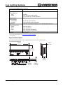
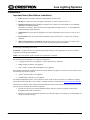
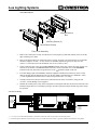
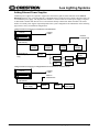
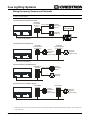
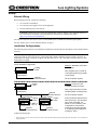
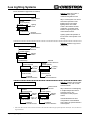
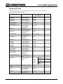
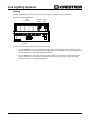
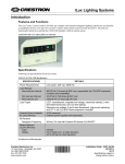
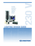
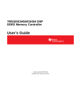
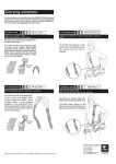
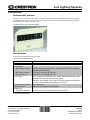
iLux Lighting Systems
Introduction
Features and Functions
The iLux® units, CLS-C6 and CLS-C6M, are complete integrated wall-mounted lighting systems that can function
as standalone devices or be part of a total Crestron® solution. The units are functionally identical except that the
CLS-C6M includes a built-in motion sensor.
CLS-C6M with Cover Open (Shown in Almond)
Specifications
Following are specifications for the iLux units.
CLS-C6 & CLS-C6M Specifications
SPECIFICATION
Power Requirements
1
Load Ratings
Max load per channel
Min load per channel
Max load per unit
Load Types
Cresnet Power Available
for Local Devices
IR Receiver
Reception Frequency
DETAILS
Line Power, 120 Vac, 60 Hz
800 W/VA (6.6 Amps @ 120 Vac), expandable via CLS-EXP expansion
modules (sold separately)
15 W/VA (0.125 Amps @ 120 Vac)
1920 W/VA (16 Amps @ 120 Vac)
2
LED , Incandescent, Magnetic Low-voltage, Neon/Cold Cathode, 2-Wire
Dimmable Fluorescent, DQG Non-Dim Lighting;
Electronic Low-voltage, 3 and 4-Wire Fluorescent, High-Inrush Switching,
3
and 277 V via CLS-EXP Series expansion modules
10 W Maximum
External power supplies sold separately
3
36 kHz, For use with Crestron IR remote CLS-IRHT8
(Continued on following page)
Crestron Electronics, Inc.
15 Volvo Drive Rockleigh, NJ 07647
Tel: 888.CRESTRON
Fax: 201.767.7576
www.crestron.com
Installation Guide – DOC. 6394F
(2013406)
03.13
Specifications subject to
change without notice.
iLux Lighting Systems
CLS-C6 & CLS-C6M Specifications (Continued)
SPECIFICATION
Motion Detector
(CLS-C6M only)
Type
Range
Default Net ID
Environmental
Temperature
Humidity
Enclosure
Overall Dimensions:
Height
Width
Depth
Weight
DETAILS
Infrared
20 to 30 feet at 4-foot elevation
(6 to 9 meters at 1.2 meter elevation)
1F
32° to 104° F (0° to 40° C)
10% to 90% RH (non-condensing)
Mounts in a 4-gang electrical box, 3 1/2" (89 mm) deep minimum
4.48 in (114 mm)
8.89 in (226 mm)
2.47 in (63 mm) for CLS-C6
2.60 in (66 mm) for CLS-C6M
23 oz (649 g)
1. If the unit is fed from an arc fault circuit interrupter, the maximum total load is 1000 W/VA to avoid nuisance tripping.
2. For a list of compatible ballasts, visit www.crestron.com/lightingcompatibility.
3. Sold separately.
Physical Description
The following illustration shows the overall dimensions for the CLS-C6 and CLS-C6M.
CLS-C6M Overall Dimensions
8.89 in
(226 mm)
2.38 in
(60 mm)
4.48 in
(114 mm)
1.88 in
(48 mm)
0.59 in
(15 mm)
CLS-C6
2 • iLux Lighting Systems: CLS-C6 & CLS-C6M
0.72 in
(18 mm)
CLS-C6M
Installation Guide – DOC. 6394F
iLux Lighting Systems
Installation
Important Notes (Read Before Installation)
•
Codes: Install in accordance with all local and national electrical codes.
•
Wiring: Use copper wire only. For supply connections, use wires rated for at least 75° C.
•
Lighting Load Types: LED, incandescent, magnetic low-voltage, neon/cold cathode, 2-wire dimmable
fluorescent, and non-dim lighting.
Electronic low-voltage, 3 and 4-wire fluorescent, high-inrush switching, and 277 V via CLS-EXP Series
expansion modules (sold separately)
•
Temperature: The iLux units are designed for use where temperatures are between 32° to 104° F (0° to
40° C).
•
Electrical Boxes: The iLux units mount in standard 4-gang electrical boxes, 3.5 inches (89 mm) deep,
minimum.
•
Make certain that power is turned off, and ensure that there is at least 4 1/2 inches (115 mm) of open
space above and below the electrical box location to permit adequate heat dissipation.
WARNING: Turn off power at the distribution panel circuit breaker. Installing with power on can result in serious
personal injury and damage to the device.
CAUTION: To reduce the risk of overheating and possible damage to other equipment, do not use to control a
receptacle or a motor-operated appliance.
NOTE: The CLS-C6 units require a neutral wire connection for operation.
The following tools and hardware are required for installation.
•
A 4-gang electrical box (not supplied), 3.5 inches (89 mm) deep, minimum.
•
Phillips torque screwdriver (not supplied)
•
Four 7/8 inch (~22 mm) pan head Phillips screws (supplied)
If the planned configuration includes connection to shade controllers, keypads or a Crestron 2-Series control system,
the following items are also required:
•
Cresnet® network cable(s) (not supplied)
•
Terminal block connector(s) (two supplied)
For detailed configuration options, refer to the latest version of the Crestron CLS-C6 & CLS-C6M iLux Lighting
System Operations Guide (Doc. 6347), which is available from the Crestron Web site (www.crestron.com/manuals).
Check that any required Cresnet wiring has been installed and verified. Then, use the following procedure to install
the iLux unit (CLS-C6M is shown in the illustrations).
1.
Feed the wires (power line from the distribution panel, load wires, plus any required Cresnet cables)
through the holes in the electrical box.
2.
Hold the rear of the CLS-C6M unit and remove the front panel and cover assembly by carefully pulling out
and up from the bottom edge.
Installation Guide – DOC. 6394F
iLux Lighting Systems: CLS-C6 & CLS-C6M • 3
iLux Lighting Systems
CLS-C6M Installation
4-Gang Electrical
Box
Mounting Screws (4)
Control Panel Overlay
Front Cover Assembly
3.
Remove the control panel overlay from the unit (it is held in place by small tabs and lifts off) to reveal the
upper mounting screw holes.
4.
Refer to the diagram below for connection of the ac wiring. All wires to be inserted in the screw terminals
should be stripped 7/16 inch (~11 mm), and screws should be tightened to between 8 and 10 in.-lbs.
(0.90 to 1.13 Newton meters). The maximum wire size is 12 AWG (3 mm2).
5.
Connect each load wire to the corresponding LOAD terminals on the unit, connect the power line hot wire
from the circuit breaker to the HOT terminal on the unit, connect all neutral wires to the NEUTRAL
terminal on the unit, and connect all ground wires to the
(ground) terminal on the unit.
6.
If Cresnet cabling is part of the installation, attach the supplied terminal block connector(s) to the Cresnet
cable(s) and plug into the appropriate port(s) on the unit. Make certain that there is a minimum 1/4 inch
(~6 mm) separation between the Class 2 Cresnet wiring and the Class 1 ac wiring.
7.
Carefully tuck all wires into the electrical box and fasten the unit to the electrical box using the four
7/8-inch (~22 mm) Phillips screws supplied.
8.
Reattach the control panel overlay to the front panel by inserting the four tabs into the slots on the unit, and
install the hinged front cover assembly by lining it up at the top and pressing the bottom edge until it snaps
into position.
CLS-C6M AC Wiring
Distribution
Panel
Hot
Circuit
Breaker1
Load 32
Load 4
Load 22
Load 52
2
Load 62
Load 1
2
Neutral
Standard Cresnet Wiring
24 – Red
Y – White
Z – Blue
G – Black
1. Use a 15 or 20 A circuit breaker depending on installation requirements. Refer to specifications for load rating details.
2. CLS-EXP expansion modules can be used in place of any or all loads shown above. Refer to expansion module documentation for wiring details.
4 • iLux Lighting Systems: CLS-C6 & CLS-C6M
Installation Guide – DOC. 6394F
iLux Lighting Systems
Adding External Power Supplies
Additional power supplies are required to support more than four keypads or shade controllers on the LOCAL
DEVICES network. Also, each C2N-SDC-DC, CSM-QMT50-DCCN and CSC-DCCN shade controller requires its
own additional power supply. The diagram below illustrates a scenario where an external power supply is required
to add a shade controller and other devices to a network that already contains four shade controllers. The actual
number of external power supplies required depends on the system configuration. The illustrations on the following
pages show a variety of installation configurations.
Adding External Power Supply for C2N-SDC-DC Controlled Shades
CLS-C6
Lighting
Loads
Crestron
Certified Wire
Cresnet
(Local Devices)
Shade
Controller
Cresnet Gnd &
Data Lines (Y, Z)
Only
Shade
Controller
Shade
Controller
Power
Supply
Keypad
GLS-SIM
Touch
Screen
Shade
Controller
Shade
Controller
Occupancy
Sensor
Photocell
Adding External Power Supply for CSM-QMT50-DCCN and CSC-DCCN Controlled Shades
CLS-C6
Cresnet
(Local Devices)
CSA-PWS225/450
Power Supply
Installation Guide – DOC. 6394F
Lighting
Loads
Crestron
Certified Wire
Shade
Shade
CSA-PWS40
Power Supply
iLux Lighting Systems: CLS-C6 & CLS-C6M • 5
iLux Lighting Systems
Wiring Occupancy Sensors and Photocells
NOTE: Ensure that all CLS-C6 and CLS-C6M devices contain the latest firmware to take advantage of the most
recently released features.
CLS-C6M with One GLS-SIM and C2N-IO
GLS-SIM
(Cresnet ID
set to C0
or C1)
Input 1 Only
Input 2 Only
GLS-O*
Occupancy
Sensor
RS-232 to
Control System
GLS-LOL
Photocell
Cresnet (Local Devices)
C2N-IO
CLS-C6M with Two GLS-SIM Units
GLS-SIM
(Cresnet ID set
to C0 or C1)
GLS-SIM
(Cresnet ID set
to C0 or C1)
GLS-O*
Occupancy
Sensor
(Input 1 Only)
GLS-LOL
Photocell
(Input 2 Only)
Cresnet (Local Devices)
CLS-C6M with One C2N-CBD-P Keypad
C2N-CBD-P
Input 1 Only
Keypad
Input 2 Only
GLS-O*
Occupancy
Sensor
GLS-LOL
Photocell
Cresnet (Local Devices)
CLS-C6M with Two C2N-CBD-P Keypads
C2N-CBD-P
Keypad
C2N-CBD-P
Keypad
GLS-O*
Occupancy
Sensor
(Input 1 Only)
GLS-LOL
Photocell
(Input 2 Only)
Cresnet (Local Devices)
*
Refer to the latest version of the Crestron CLS/CLSI-C6 & CLS/CLSI-C6M iLux Light System Operations Guide (Doc. 6347) for details on
supported devices.
6 • iLux Lighting Systems: CLS-C6 & CLS-C6M
Installation Guide – DOC. 6394F
iLux Lighting Systems
Setup
Network Wiring
When wiring the network, consider the following:
•
Use Crestron Certified Wire.
•
Use Crestron power supplies for Crestron equipment.
•
Provide sufficient power to the system.
CAUTION: Insufficient power can lead to unpredictable results or damage to the equipment. Please use
the Crestron Power Calculator to help calculate how much power is needed for the system
(http://www.crestron.com/calculators).
For networks with 20 or more devices, use a Cresnet Hub/Repeater (CNXHUB) to maintain signal quality.
For more details, refer to “Check Network Wiring” on page 11.
Installation Configurations
The following figures illustrate five installation configurations and include brief descriptions of the rationale behind
each one.
NOTE: The power usage requirements on the local devices network is different from that described above. The
CLS-C6 provides 24 Vdc power for up to four keypads and/or shade controllers on the local device network. An
additional power supply is required to support more than four devices. Also, each shade controller requires its own
additional power supply.
CLS-C6 Installation Configurations
Method 1: Standalone CLS; Most
common way.
Lighting
Loads
CLS-C6
Cresnet
(Local Devices)
Why? Simplest way to control up
to six lighting loads and six shade
control groups.
Optional
Cresnet Devices*
No control system required.
Lighting
Loads
CLS-C6
Cresnet
(Local Devices)
Cresnet
(Control System)
CLS-C6
Cresnet
(Local Devices)
Lighting
Loads
Up to 8
Optional
Cresnet Devices*
Method 2: Primary CLS with
multiple secondary CLS units.
Optional
Cresnet Devices*
Cresnet
(Control System)
Lighting
CLS-C6
Loads
Cresnet
(Local Devices)
Optional
Cresnet Devices*
Why? Large room with more than
six lighting loads or shade groups.
No control system required.
Scene recall and master dimmers
affect entire room. Can still adjust
each circuit individually. For
details on room combining, refer
to Appendix E in the Crestron
CLS/CLSI-C6 & CLS/CLSI-C6M
iLux Lighting System Operations
Guide (Doc. 6347).
(Continued on following page)
*
Refer to the latest version of the Crestron CLS/CLSI-C6 & CLS/CLSI-C6M iLux Light System Operations Guide (Doc. 6347) for details on
supported devices.
Installation Guide – DOC. 6394F
iLux Lighting Systems: CLS-C6 & CLS-C6M • 7
iLux Lighting Systems
CLS-C6 Installation Configurations (Continued)
Method 3: Same as (1) plus a
2-Series control system
communicating with the CLS.
2-Series Control System
Cresnet
Cresnet
(Control System)
Other Cresnet
Devices
Why? Control system can control
and monitor operation of the
lighting system. Can trigger
lighting scenes from touch
screens, RF wireless remotes,
computers, or real-time clock.
Buttons on lighting system can
control other functions.
Lighting
Loads
CLS-C6
Cresnet
(Local Devices)
Optional
Cresnet Devices*
Lighting system still operates on
its own if the control system is not
running.
Method 4: Variation of (3), but for
a large room.
2-Series Control System
Cresnet
Cresnet
(Control System)
CLS-C6
Other Cresnet
Devices
Lighting
Loads
Cresnet
(Local Devices)
Optional
Cresnet Devices*
Cresnet
(Control System)
Lighting
Loads
CLS-C6
Cresnet
Up to 8
(Local Devices)
Cresnet
(Control System)
Lighting
Loads
CLS-C6
Cresnet
(Local Devices)
Optional
Cresnet Devices*
Optional
Cresnet Devices*
2-Series Control System
Cresnet
Cresnet
(Control System)
Lighting
CLS-C6
Loads
Cresnet
(Local Devices)
Up to 8
Optional
Cresnet Devices*
*
Other Cresnet
Devices
Cresnet
(Control System)
Lighting
Loads
CLS-C6
Cresnet
(Local Devices)
Optional
Cresnet Devices*
Method 5: 2-Series control system
with multiple CLS units on main
Cresnet network.
Why? Monitor and control lighting
in multiple independent rooms.
Combine rooms in any
arrangement under program
control.
Includes all features of other
configurations. Each individual
CLS system can operate without a
control system.
Refer to the latest version of the Crestron CLS/CLSI-C6 & CLS/CLSI-C6M iLux Light System Operations Guide (Doc. 6347) for details on
supported devices.
8 • iLux Lighting Systems: CLS-C6 & CLS-C6M
Installation Guide – DOC. 6394F
iLux Lighting Systems
Supported Devices
The following table lists devices supported by the iLux units and their power requirements.
Supported Devices Power Requirements
NAME
DESCRIPTION
CRESNET POWER
FACTOR (W)
MAX QTY
C2N-DB6
6-Button Keypad
3 watts
16
C2N-DB8
8-Button Keypad
3 watts
16
C2N-DB12
12-Button Keypad
3 watts
16
C2N-CBD/CBF
(All Models)
®
Cameo Keypad
0.5 watts
16
C2NI-CB/ INETI-CB
Cameo Keypad
(International)
0.5 watts
16
C2N-IO
Control Port
Expansion Module
1 watt
1
C2N-SDC
Shade and Drape
Controller
3 watts
16
C2N-SDC-DC
Shade and Drape
Controller, 24V DC
Up to 32 watts
16
C2N-SSC-2
Somfy Shade
Controller
1 watt
16
CNX-B2
2-Button Keypad
3 watts
16
CNX-B4
4-Button Keypad
3 watts
16
CNX-B6
6-Button Keypad
3 watts
16
CNX-B8
8-Button Keypad
3 watts
16
CNX-B12
12-Button Keypad
3 watts
16
CSC-ACCN
Shade Interface
N/A
16
CSC-DCCN
Shade Interface
N/A
16
CSC-DRPCN
Drapery Track
Interface
N/A
16
CSM-QMT50-DCCN
Crestron Shade
Motor
N/A
16
GLS-SIM
Sensor Integration
Module
1 watt
plus
attached
sensor
wattage
Partitions
36
Occupancy
sensing
2
BMS
integration
4
GLS-ODT & GLS-OIR
Series
Occupancy Sensors
1 watt
2
TPS-4L
3.6 in Wall-Mount
Touch Screen
5 watts
2
TPS-6L
5.7 in Wall-Mount
Touch Screen
15 watts
2
Installation Guide – DOC. 6394F
iLux Lighting Systems: CLS-C6 & CLS-C6M • 9
iLux Lighting Systems
Testing
The following illustration shows the front panel of the unit and the controls used during installation.
Front Panel Controls and Indicators
LED
Bar Graphs
1
2
3
4
Two-Digit Lights
Display Button
5
6
M in
S ec
^
^
S cene 1
S cene 2
S cene 3
S cene 4
S cene 5
Ligh ts
S hade s
S ave
C an cel
S cene 6
^
ON
^
OFF
Function
Buttons
Verify the basic installation and wiring connections as follows:
1.
Press the Lights button to enable manual light control, and press the right side and the left side of each of
the function buttons to increase and decrease the lighting level of those loads. Verify that the intended loads
and corresponding LED bar graphs respond appropriately.
2.
Press the OFF button to turn off all loads. The loads ramp down to off while the two-digit display counts
down to off (blank). Two seconds after all lights have turned off, the unit’s master air-gap relay opens
making it safe to service the lighting installations.
10 • iLux Lighting Systems: CLS-C6 & CLS-C6M
Installation Guide – DOC. 6394F
iLux Lighting Systems
Troubleshooting
The following table provides corrective action for possible trouble situations. If further assistance is required, please
contact a Crestron customer service representative.
CLS-C6/C6M Installation Troubleshooting
TROUBLE
Unit does not function.
*
POSSIBLE
CAUSE(S)
CORRECTIVE ACTION
Unit is not
receiving line
power.
Verify that the unit is properly connected to
the power line and that the circuit breaker is
closed.
Loads are not
connected.
Verify that the loads are operational and that
they are connected to the iLux unit.
Loads turn on and off,
but do not dim.
Wrong load type
settings.
Correct load type settings. *
Lights flicker at low
levels
Incorrect low-end
limit setting.
Change low-end limit setting. *
Refer to the latest version of the Crestron CLS-C6 & CLS-C6M iLux Lighting System Operations Guide (Doc. 6347) for details on setting
load types and low-end limits.
Check Network Wiring
Use the Right Wire
To ensure optimum performance over the full range of the installation topology, use Crestron Certified Wire only.
Failure to do so may incur additional charges if support is required to identify performance deficiencies because of
using improper wire.
Calculate Power
CAUTION: Use only Crestron power supplies for Crestron equipment. Failure to do so could cause equipment
damage or void the Crestron warranty.
CAUTION: Provide sufficient power to the system. Insufficient power can lead to unpredictable results or damage
to the equipment. Use the Crestron Power Calculator to help calculate how much power is needed for the system
(www.crestron.com/calculators).
When calculating the length of wire for a particular Cresnet run, the wire gauge and the Cresnet power usage of each
network unit to be connected must be taken into consideration. Use Crestron Certified Wire only. If Cresnet units
are to be daisy chained on the run, the Cresnet power usage of each network unit to be daisy chained must be added
together to determine the Cresnet power usage of the entire chain. If the unit is run from a Crestron system power
supply network port, the Cresnet power usage of that unit is the Cresnet power usage of the entire run. The wire
gauge and the Cresnet power usage of the run should be used in the following equation to calculate the cable length
value on the equation’s left side.
Cable Length Equation
L<
40,000
RxP
Where: L = Length of run (or chain) in feet
R = 6 Ohms (Crestron Certified Wire: 18 AWG (0.75 mm2 ))
or 1.6 Ohms (Cresnet HP: 12 AWG (4 mm2 ))
P = Cresnet power usage of entire run (or chain)
Make sure the cable length value is less than the value calculated on the right side of the equation. For example, a
Cresnet run using 18 AWG Crestron Certified Wire and drawing 20 watts should not have a length of run more than
333 feet (101 meters). If Cresnet HP is used for the same run, its length could extend to 1250 feet (381 meters).
NOTE: All Crestron certified Cresnet wiring must consist of two twisted pairs. One twisted pair is the +24V
conductor and the GND conductor and the other twisted pair is the Y conductor and the Z conductor.
Installation Guide – DOC. 6394F
iLux Lighting Systems: CLS-C6 & CLS-C6M • 11
iLux Lighting Systems
Strip and Tin Wire
When daisy chaining Cresnet units, strip the ends of the wires carefully to avoid nicking the conductors. Twist
together the ends of the wires that share a pin on the network connector and tin the twisted connection. Apply solder
only to the ends of the twisted wires. Avoid tinning too far up the wires or the end becomes brittle. Insert the tinned
connection into the Cresnet connector and tighten the retaining screw. Repeat the procedure for the other three
conductors.
Add Hubs
Use of a Cresnet Hub/Repeater (CNXHUB) is advised whenever the number of Cresnet devices on a network
exceeds 20 or when the combined total length of Cresnet cable exceeds 3000 feet (914 meters).
Further Inquiries
To locate specific information or resolve questions after reviewing this guide, contact Crestron's True Blue Support
at 1-888-CRESTRON [1-888-273-7876] or refer to the listing of Crestron worldwide offices on the Crestron Web
site (www.crestron.com/offices) for assistance within a particular geographic region.
To post a question about Crestron products, log onto the Online Help section of the Crestron Web site
(www.crestron.com/onlinehelp). First-time users must establish a user account to fully benefit from all available
features.
Future Updates
As Crestron improves functions, adds new features and extends the capabilities of the CLS-C6 and CLS-C6M,
additional information may be made available as manual updates. These updates are solely electronic and serve as
intermediary supplements prior to the release of a complete technical documentation revision.
Check the Crestron Web site periodically for manual update availability and its relevance. Updates are identified as
an “Addendum” in the Download column.
12 • iLux Lighting Systems: CLS-C6 & CLS-C6M
Installation Guide – DOC. 6394F
iLux Lighting Systems
Return and Warranty Policies
Merchandise Returns / Repair Service
1.
No merchandise may be returned for credit, exchange or service without prior authorization from Crestron.
To obtain warranty service for Crestron products, contact an authorized Crestron dealer. Only authorized
Crestron dealers may contact the factory and request an RMA (Return Merchandise Authorization) number.
Enclose a note specifying the nature of the problem, name and phone number of contact person, RMA
number and return address.
2.
Products may be returned for credit, exchange or service with a Crestron Return Merchandise
Authorization (RMA) number. Authorized returns must be shipped freight prepaid to Crestron, 6 Volvo
Drive, Rockleigh, N.J. or its authorized subsidiaries, with RMA number clearly marked on the outside of
all cartons. Shipments arriving freight collect or without an RMA number shall be subject to refusal.
Crestron reserves the right in its sole and absolute discretion to charge a 15% restocking fee plus shipping
costs on any products returned with an RMA.
3.
Return freight charges following repair of items under warranty shall be paid by Crestron, shipping by
standard ground carrier. In the event repairs are found to be non-warranty, return freight costs shall be paid
by the purchaser.
Crestron Limited Warranty
Crestron Electronics, Inc. warrants its products to be free from manufacturing defects in materials and workmanship
under normal use for a period of three (3) years from the date of purchase from Crestron, with the following
exceptions: disk drives and any other moving or rotating mechanical parts, pan/tilt heads and power supplies are
covered for a period of one (1) year; touch screen display and overlay components are covered for 90 days; batteries
and incandescent lamps are not covered.
This warranty extends to products purchased directly from Crestron or an authorized Crestron dealer. Purchasers
should inquire of the dealer regarding the nature and extent of the dealer's warranty, if any.
Crestron shall not be liable to honor the terms of this warranty if the product has been used in any application other
than that for which it was intended or if it has been subjected to misuse, accidental damage, modification or
improper installation procedures. Furthermore, this warranty does not cover any product that has had the serial
number altered, defaced or removed.
This warranty shall be the sole and exclusive remedy to the original purchaser. In no event shall Crestron be liable
for incidental or consequential damages of any kind (property or economic damages inclusive) arising from the sale
or use of this equipment. Crestron is not liable for any claim made by a third party or made by the purchaser for a
third party.
Crestron shall, at its option, repair or replace any product found defective, without charge for parts or labor.
Repaired or replaced equipment and parts supplied under this warranty shall be covered only by the unexpired
portion of the warranty.
Except as expressly set forth in this warranty, Crestron makes no other warranties, expressed or implied, nor
authorizes any other party to offer any warranty, including any implied warranties of merchantability or fitness for a
particular purpose. Any implied warranties that may be imposed by law are limited to the terms of this limited
warranty. This warranty statement supersedes all previous warranties.
The specific patents that cover Crestron products are listed at patents.crestron.com.
Crestron, the Crestron logo, Cameo, Cresnet, and iLux are trademarks or registered trademarks of Crestron Electronics, Inc. in the United States
and/or other countries. UL and the UL logo are either trademarks or registered trademarks of Underwriters Laboratories, Inc. in the United States
and/or other countries. Other trademarks, registered trademarks and trade names may be used in this document to refer to either the entities
claiming the marks and names or their products. Crestron disclaims any proprietary interest in the marks and names of others. Crestron is not
responsible for errors in typography or photography.
This document was written by the Technical Publications department at Crestron.
©2013 Crestron Electronics, Inc.
Installation Guide – DOC. 6394F
iLux Lighting Systems: CLS-C6 & CLS-C6M • 13
iLux Lighting Systems
This page is intentionally left blank.
14 • iLux Lighting Systems: CLS-C6 & CLS-C6M
Installation Guide – DOC. 6394F