1
o o o o o o o o o o o o o o o o o o o o o o o o o o o o o o o o o o o o o o o o o o o o o o o o o o o o o o o o o o o o o o o o o o o o o o o o o o o o o o o o o o o o
OWNER’S MANUAL
o o o o o o o o o o o o o o o o o o o o o o o o o o o o o o o o o o o o o o o o o o o o o o o o o o o o o o o o o o o o o o o o o o o o o o o o o o o o o o o o o o o o
Cinema 11v
High-Definition Video Processor
NOTE: Before installing your new component, please read this manual
carefully as it will inform you of the product specifications, proper
installation and correct operating procedures for your unit. Also included
in this manual are guidelines on how to service and care for your new
Cary Audio Design product.
TABLE OF CONTENTS
Important Safety Instructions ........................................................................................................... 3
Welcome
Thank You ......................................................................................................................................... 5
Product Features ................................................................................................................................ 6
Unpacking ......................................................................................................................................... 7
Specifications
Inputs/Outputs .................................................................................................................................. 8
Performance ..................................................................................................................................... 8
Performance of Composite and S-Video ................................................................................................ 9
Digital Audio ...................................................................................................................................... 9
Control .............................................................................................................................................. 9
Power Requirements ........................................................................................................................... 9
Controls and Displays
Front Panel....................................................................................................................................... 10
Rear Panel ....................................................................................................................................... 11
Remote Control Device ...................................................................................................................... 13
Connections
One television or monitor with an HDMI input ..................................................................................... 15
One television or monitor along with one surround sound processor with an HDMI input and output ........ 16
Two televisions or monitors along with one surround sound processor with an HDMI input and output ..... 17
Two televisions or monitors along with two surround sound processors with an HDMI input and output.... 18
Setup Menu
Input Select ..................................................................................................................................... 19
Input Assign
Change Input Names ........................................................................................................................ 19
Assign Video Inputs ......................................................................................................................... 20
Assign Audio Inputs ......................................................................................................................... 21
Picture Control................................................................................................................................. 22
Output 1 Setup
Resolution ..................................................................................................................................... 23
Aspect Ratio .................................................................................................................................. 23
Color Space ................................................................................................................................... 25
Output 2 Setup ................................................................................................................................ 25
Test Patterns ................................................................................................................................... 25
Advanced Settings
Password ...................................................................................................................................... 26
TABLE OF CONTENTS
Bright ........................................................................................................................................... 27
Edit Custom Name ........................................................................................................................... 27
IR Controls .................................................................................................................................... 28
Rear IR Mode ................................................................................................................................. 28
Zoom ........................................................................................................................................... 29
Trigger ......................................................................................................................................... 29
Picture-in-Picture (PIP) & Picture-by-Picture (PBP) ................................................................................... 29
3D Comb Filter ................................................................................................................................ 30
True Life ....................................................................................................................................... 30
MANR ........................................................................................................................................... 31
Information ................................................................................................................................... 31
Update ......................................................................................................................................... 32
EDID Channel ................................................................................................................................ 32
Restore Default ................................................................................................................................ 33
Exit Menu ........................................................................................................................................ 33
Sound Options
Sound through a Television ............................................................................................................... 34
Sound through a Surround Sound Processor ....................................................................................... 34
Restoring Sound to a Television ......................................................................................................... 34
Service and Care
Care and Cleaning ............................................................................................................................ 35
Factory Service................................................................................................................................. 35
Non-Warranty Repairs ........................................................................................................................ 35
Limited Warranty ............................................................................................................................... 36
IMPORTANT SAFETY INSTRUCTIONS
WARNING: The triangle with the lightning flash symbol
displayed on the unit advises the user of dangerous uninsulated voltage inside the product’s enclosure.
CAUTION: To reduce the risk of electric shock, do not remove
the cover. There are no user-serviceable parts inside; it is
recommended that only qualified personnel service this
component.
ALERT: The triangle with the exclamation point symbol on the component suggests that the owner refer to
important operating and maintenance instructions in the owner’s manual.
1.
2.
3.
4.
5.
6.
7.
8.
9.
10.
11.
12.
13.
14.
OWNER’S MANUAL: Before powering up the equipment, read all safety and operating instructions and follow
them as instructed. Retain the safety and operating instructions for future reference.
ATTACHMENTS: Use only those attachments recommended by the unit manufacturer, as others may cause
hazards.
ACCESSORIES: Do not place the unit on an unstable cart, stand, tripod, bracket, or table. The unit may fall,
causing injury to a person or damage to the unit. Mount the unit according to the manufacturer’s instructions with
the suggested mounting accessory.
WALL OR CEILING MOUNTING: Mount the unit to a wall or ceiling only in the manner recommended by the
manufacturer.
WATER AND MOISTURE: Do not use the unit near water (for example, near a swimming pool, bath tub, wash
bowl, kitchen sink, or laundry tub) or in a damp environment (like a basement or outside in the rain).
OBJECT AND LIQUID ENTRY: Do not push objects of any kind into the unit through openings as they could touch
dangerous voltage points and short-out parts, possibly resulting in a fire or electric shock. Avoid spilling liquid of any
kind on the unit. If water or any metal object (such as a paper clip, coin, or staple) accidentally falls inside the unit,
disconnect it from the AC power source immediately and contact Cary Audio Design for further instructions.
HEAT: Position the unit away from heat sources such as radiators, heat registers, stoves, or other units (including
amplifiers) that produce heat.
VENTILATION: Slots and openings in the cabinet create ventilation to protect the component from overheating.
These openings on the top and bottom panels must remain unobstructed. Allow at least six inches (16 cm.) of
clearance above the unit and an opening behind the unit for airflow. Do not place the unit on a bed, sofa, rug, builtin bookcase, or rack without adequate ventilation.
GROUNDING OR POLARIZATION: As a safety feature, the unit may be equipped with a polarized alternating
current line plug in which one blade is wider than the other. This plug will fit into the power outlet only one way. If
you cannot insert the plug fully into the outlet, try reversing the plug. If the plug still will not fit, contact a licensed
electrician to update your obsolete outlet. Do not defeat the safety purpose of the polarized plug.
POWER SOURCES: Operate the unit only from the power source indicated on the marking label. If you are
unsure of the type of power supplied to your home, consult your unit dealer or local power company.
POWER CORD PROTECTION: Arrange power supply cords so that they do not suffer from foot traffic or pinching
by items placed on or against them. Pay close attention to cords where plugs enter the AC outlet and where they exit
from the unit.
LIGHTNING: For added protection during a lightning storm or when the component is idle for long periods of
time, unplug the unit from the wall outlet and disconnect the antenna or cable system. This will help protect the
unit from lightning and power line surge damage.
POWER LINES: Do not locate an outside antenna system in the vicinity of overhead power lines or other electric
light or power circuits. When installing an outside antenna system, take extreme care to avoid touching the power
lines or circuits; contact with them could be fatal.
OVERLOADING: Do not overload wall outlets, extension cords, or integral convenience receptacles as this
increases the risk of fire or electric shock.
3
IMPORTANT SAFETY INSTRUCTIONS
15. REPLACEMENT PARTS: When replacement parts are required, be sure the service technician has used
replacement parts specified by the manufacturer or those having the same characteristics as the original parts.
Unauthorized substitutions may result in fire, electric shock or other hazards.
16. SAFETY CHECK: Upon completion of any service or repairs to the unit, ask the service technician to perform
safety checks to ensure the unit is in proper operating condition.
17. IMPORTANT SAFETY NOTE:
•
Before connecting a new product such as the Cary Audio Design MS-1 to your audio or home theater system,
turn off all other equipment (preferably unplugging them from the AC power source). Many audio components
feature automatic turn-on circuits that may activate during an installation, potentially causing damage to
electronic components or speakers. This type of damage is not covered by product warranties, and Cary Audio
Design specifically disclaims responsibility for any such damage.
•
Power Cord: The removable power cord provided with your player was specifically designed
for use with this product, but other AC cords may be used. Consult your dealer for advice on AC
power cords and high quality wire in your system.
•
AC Fuse: The fuse is located inside the chassis and is not user serviceable. If the unit does not power up,
contact an authorized service representative.
•
Wiring: Cables running inside walls should have the appropriate markings to indicate compliance and listing by
the UL, CSA or other standards required by the UL, CSA, NEC, or your local building code. Questions about
cables inside of walls should be directed to a qualified custom installer, licensed electrician, or low-voltage
contractor.
18. RECORDING COPYRIGHT: Recording of copyrighted material for other than personal use is illegal without
permission of the copyright holder.
19. NOTE TO CATV SYSTEM INSTALLER: This reminder is provided to call the CATV system installer's attention to
article 820-40 of the NEC, ANSI/NFPA 70, which provides guidelines for proper grounding and, in particular, specifies
that the cable ground shall be connected to the grounding system of the building as close to the point of cable entry
as practical.
20. FCC INFORMATION FOR USER:
•
CAUTION: Any changes or modifications not expressly approved by Cary
Audio Design could void the user's authority to operate the equipment.
•
NOTE: This equipment has been tested and found to comply with the limits
for a Class B digital device pursuant to Part 15 of the FCC Rules.
•
These limits are designed to provide reasonable protection against harmful interference in a residential
installation. This equipment generates and can radiate radio frequency energy, and if not installed and used in
accordance with the instructions it may cause harmful interference to radio communications. However, there is
no guarantee that interference will not occur in a particular installation. If this equipment does cause harmful
interference to radio or television reception, which can be determined by turning the equipment off and on, the
user is encouraged to try to correct the interference by one or more of the following measures:
•
Reorient or relocate the receiving antenna.
•
Increase the separation between the equipment and receiver.
•
Connect the equipment into an outlet on a circuit different from where the receiver is
connected.
21. OUTDOOR ANTENNA INSTALLATION/SAFE ANTENNA AND CABLE CONNECTION:
•
If an outside antenna or cable system is connected to the equipment,
be sure the antenna or cable system is grounded in order to provide
protection against built-up static charges and voltage surges. Article
810 of the National Electrical Code, ANSI/NFPA 70 (in Canada, Part 1
of the Canadian Electrical Code) provides information regarding
proper grounding of the mast and supporting structure, grounding of
the lead-in wire to an antenna discharge unit, size of grounding
conductors, location of antenna discharge unit, connection to
grounding electrodes and requirements for the grounding electrode.
• Outside antenna system should be located well away from power lines,
electric light or power circuits and where it will never come into contact
with these power sources if it should happen to fall. When installing an
outside antenna, take extreme care to avoid touching power lines,
circuits and other power sources as this could be fatal. Because of the
hazards involved, antenna installation should be left to a professional.
4
WELCOME
Thank You and Congratulations on Becoming a Cinema 11v Owner!
We at Cary Audio Design would like to thank you for purchasing the new Cinema 11v HD Video
Processor. The Cinema 11v will elevate the quality of your experience with your home audio and
video system by acting as an intelligent central switching hub and video processor. When your
audio/video source devices connect to your high-definition television and audio/video receiver,
switching from one component to another will become smooth and seamless.
Most home audio/video systems consist of many independent components. The task of
connecting, configuring, optimizing and operating the system is left to the user. The Cinema
11v makes that headache a thing of the past.
Quite a unique product, the Cinema 11v helps simplify your system’s interconnections while
delivering both ease of use and world class video processing to your high- definition television.
The more components your system has, the more you benefit from the simplicity and
performance the Cinema 11v delivers.
The Cinema 11v is based on the Genesis FLI30436 video processing chip. The FLI30436 chip
offers highly advanced, dual-channel applications of Picture-in-Picture (PIP) and Picture-by-Picture
(PBP). Two video decoders with 3D comb filters and two channels of DCDi® processing provide
the highest quality picture for a two-channel application.
True 10-bit performance throughout the device, an Advanced Color Management (ACM3D), and a DDR memory with enhanced picture data capacity provide an exceptionally high
level of video quality. The Cinema 11v’s integrated Analog Front End (AFE) includes two Triple
analog to digital converters and two Faroudja® Intellicomb™ 3D comb filters.
The Cinema 11v features dual HDMI output connectors. This configuration delivers optimal
performance and ease of use in a system enjoying both two digital displays and two audio/video
receivers simultaneously. The Cinema 11v communicates with your display to obtain its preferred
format, then automatically adjusts its processing to match the display’s preferred format.
Similarly, it communicates with your audio/video receiver to learn its audio capabilities, then
combines display information and communicates EDID (extended display information data)
capability back to the source components thus providing optimized output. The Cinema 11v can
manage your system automatically, or
if you prefer, you can manually control your system through the Cinema 11v. Either way, the
Cinema 11v makes life easier.
The Cinema 11v was designed to remain viable in a future of rapidly emerging and
changing digital technologies. Its rear panel RS-232 serial port connector allows for home
automation serial control as well as flash memory upgrades.
We at Cary Audio Design firmly believe in high performance products that offer an incredible
value for the money. With its leading edge technology, exceptional picture performance, and ease
of use, the Cinema 11v is without question the highest performing HD video processor available
today.
Thank you for your continued support. Enjoy your music and movies!
5
WELCOME
PRODUCT FEATURES
The Cinema 11v is a versatile high-definition video processor designed to deliver
maximum image quality with powerful digital video processing, maximizing any standard
or high-definition input signal.
The Cinema 11v functions as a central video switching system, as the processor is the ideal location
for video source selection to be made. For instance, if the projector handled the switching, multiple
cables would be required. If the surround-sound processor coordinated the switching, the audio
quality could be compromised by digital video noise.
The Cinema 11v includes twenty-five video inputs–eight composite, eight S-Video, two
component video, one RGBHV, and six HDMI. It offers eleven audio inputs–six HDMI, two
assignable coaxial, two assignable optical digital, and one assignable analog pair.
The processor features aspect ratio presets for 4:3, 5:4, 16:9, 2.35:1 and a user preset. The
processor offers separate display and screen adjustments plus under scan adjustment to
compensate for display over scan where present.
The intuitive on-screen display is easily read on the bright two-line x 20-character front panel
display’s screen. Eight display profiles are provided plus thirty-two output resolution formats,
sync type, color space and gamma output settings. Ten test patterns are built-in.
Operation is via the front panel controls, IR remote or RS232 interface.
The Cinema 11v features a wide range of features designed to deliver the very highest quality
from any input signal. Mosquito noise reduction reduces noise that may appear at the edges of
compressed images, while fine detail enhancement extracts the detail from lower resolution
sources. Edge enhancement sharpens edge transitions in images without adding ringing effects.
The Cinema 11v features six HDMI v1.3a inputs handling up to 1080p-60 and two HDMI
outputs, ISFccc RGB capability on each input for full calibration, and two programmable
triggers to control motorized screens and other equipment..
The Cinema 11v includes flexible digital and analog audio switching and routing with four digital
and one analog audio input, all assignable in addition to audio on the HDMI inputs. There are
optical and coaxial S/PDIF digital outputs as well as audio on the HDMI outputs.
The Cinema 11v offers the following features:
Six HDMI v1.3a inputs and two HDMI v1.3a outputs
Eight composite and eight S-Video inputs
Two component video inputs
One RGB analog video input
Two assignable coaxial digital audio inputs
Two assignable TOSLINK digital audio inputs
One assignable stereo pair analog audio input
6
WELCOME
One coaxial digital audio output for HDMI input signal
One TOSLINK digital audio output for HDMI input signal
Two component video outputs
RS-232 input connector for flash memory software upgrades and configuration
tool downloads
RS-232 output connector for Cinema 11a use
Two 12-volt output trigger connections with 1/8” mini plug connectors
One 12-volt input trigger connection with 1/8” mini plug connectors
One IR input connection with 1/8” mini plug connector
UNPACKING
About the Box
Your Cary Audio Design product was shipped in a carton particularly designed to protect its
contents, and special care has been taken to prevent damage during shipping.
Carefully remove your new component from its packing carton and examine it closely for signs of
shipping damage. If shipping damage is discovered, document the damage with photographs,
contact the transport carrier immediately, and retain the packing as evidence.
We strongly recommend saving all original packing cartons to protect your component for
storage or future shipping.
Included in the Box
When unpacking your Cinema 11v HD Video Processor, make sure the following items are
included:
Cinema 11v HD Video Processor
AC Power Cord
One Remote Control Device (batteries already installed)
Owner’s Manual
Warranty Card
Warranty Card
If you are the original purchaser of this unit and you purchased it in the United States,
complete the enclosed warranty registration card and return it to Cary Audio Design within
fifteen days of your purchase. Warranty restrictions apply. Consult the warranty section of this
manual for details. Please keep a copy of the original sales receipt from your authorized Cary
Audio Design dealer to validate the warranty if necessary.
7
SPECIFICATIONS
The Cinema 11v is designed for long-term stability in virtually any home operating situation.
However, if the unit is operated outside the parameters outlined in this owner's manual, damage
may result. Please read this manual carefully before operating your new Cinema 11v processor.
The following section describes the Cinema 11v’s basic specifications. The specifications are
subject to change without notice or obligation.
INPUTS/OUTPUTS
................................................................................................................................................
Video Inputs
8 composite (RCA)
8 S-Video
2 component
1 RGBHV (BNC)
................................................................................................................................................
Digital Audio Inputs
2 coaxial (RCA) for the two single-ended inputs
2 TOSLINK for the two single-ended inputs
1 analog stereo pair input
................................................................................................................................................
HDMI Inputs
6 HDMI V1.3a inputs
................................................................................................................................................
HDMI Outputs
2 HDMI V1.3a output
................................................................................................................................................
Video Outputs
1 component (RCA)
1 component (BNC)
................................................................................................................................................
Digital Audio Outputs
1 coaxial (RCA) output
1 TOSLINK output
................................................................................................................................................
Control Port
2 DB-9F
................................................................................................................................................
PERFORMANCE
................................................................................................................................................
HDMI Receiver
Silicon image Sil9135A
................................................................................................................................................
HDMI Transmitter
Silicon image Sil9134
................................................................................................................................................
Processor
GENESIS dual 10-bit processor for HDMI 1
Anchor Bay 10-bit processor for HDMI 2
................................................................................................................................................
Component
TI TVP7002 triple 10-bit ADC
................................................................................................................................................
Video Converter
TI THS8200 triple 11-bit video DAC
................................................................................................................................................
8
SPECIFICATIONS
PERFORMANCE OF COMPOSITE AND S-VIDEO
................................................................................................................................................
Color system
NTSC and PAL compatible
................................................................................................................................................
Input level
1.0 volt peak-to-peak
................................................................................................................................................
Impedance
75 ohm
................................................................................................................................................
Input Return Loss
40 dB
................................................................................................................................................
Signal /Noise Ratio
>70 dB
................................................................................................................................................
DIGITAL AUDIO
................................................................................................................................................
Input Receiver
Cirrus CS8416 for coaxial and TOSLINK input
................................................................................................................................................
Sample Rates
44.1, 48, 88.2, 96, 192 kHz
................................................................................................................................................
Accepts
16-24 bits PCM audio, Dolby TrueHD, Dolby Plus, Dolby
Digital EX, dts-HD Master
Audio, dts-HD High-Resolution Audio, dts and dts
ES discrete data formats
................................................................................................................................................
CONTROL
................................................................................................................................................
RS-232 Interface
Connection
DB-9F, straight-wired
Pinout (Statement DI side)
Pin 2: Tx, Pin 3: Rx, Pin 5: Ground
Baud Rate
9600
Configuration
8 data bits, 1 stop bit, no parity bits,
flow control (RTS, CTS, NONE)
................................................................................................................................................
Trigger Outputs
Polarity
3.5 mm mono (tip positive), sleeve negative
150 mA
Maximum Current at 12 VDC
Sequential Delay
100 ms
................................................................................................................................................
POWER REQUIREMENTS
...............................................................................................................................................
Power Requirements
117VAC or 220VAC 50-60Hz
...............................................................................................................................................
Power Consumption
Maximum 95 watts
................................................................................................................................................
9
CONTROLS AND DISPLAYS
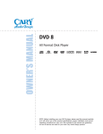
FRONT PANEL
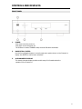
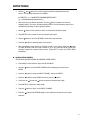
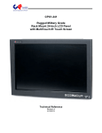
1.
POWER
Press once to turn the power on.
Press again to turn the power off.
The Cinema 11v enters STANDBY mode; the blue LED above illuminates.
2.
NAVIGATION / ENTER
Use the four navigation buttons to move through menu options shown on the Cinema 11v
display. Use ENTER to confirm menu selections.
3.
ALPHANUMERIC DISPLAY
This twenty-character display provides a wide range of information about the
operation of the Cinema 11v.
10
CONTROLS AND DISPLAYS
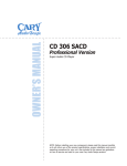
REAR PANEL
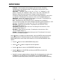
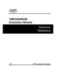
1.
HDMI INPUT CONNECTORS
Connect components with an HDMI output such as cable and satellite boxes as well as DVD
and Blu-ray players.
2.
COMPONENT VIDEO INPUT
Connect devices with component video outputs such as DVD and Blu-ray players.
3.
RGBHV VIDEO INPUT
Connect the devices with RGBHV video outputs such as DVD and Blu-ray players.
4.
HDMI 1 Output Connector
Connect a television or projector with an HDMI input.
5.
HDMI 2 Output Connector
Connect a television or projector with an HDMI input.
6.
Cary Digi–Link Port
This port is for upgrade use only.
7.
COMPONENT VIDEO OUTPUT
Connect devices with component video inputs such as a television or monitor.
8.
RS-232 PORT OUT
Use this port with a Cinema 11a to operate the Cinema 11v.
9.
RS-232 PORT
Use this in conjunction with an external controller to operate the Cinema 11v.
(Custom installation use only)
11
CONTROLS AND DISPLAYS
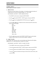
10. AC INLET CONNECTOR
Plug the power cord into this AC inlet, then into the power outlet on the wall.
11. DC TRIGGER OUTPUT TERMINALS
Connect devices (like screen, curtains, and lights) to be triggered by DC + 12V.
12. DC TRIGGER INPUT TERMINALS
Input DC + 12V control by external controller to switch the power on and off.
13. IR INPUT TERMINAL
Connect an infrared sensor to this jack when the front sensor is blocked by
cabinetry.
14. DIGITAL AUDIO OUT (TOSLINK OPTICAL)
Audio from your HDMI input is output here digitally.
15. DIGITAL AUDIO OUT (COAXIAL)
Audio from your HDMI input is output here digitally.
16. DIGITAL INPUTS (RCA COAXIAL)
These digital inputs accept digital audio signals from CD players, DVD players and other
digital source components.
17. DIGITAL INPUTS (TOSLINK OPTICAL)
These digital inputs accept digital audio signals from CD players, DVD players and other
digital source components.
18. ANALOG AUDIO IN (RCA)
Use these jacks for connection to CD, DVD, TV, and VCR input options.
19. COMPOSITE VIDEO INPUT
Use to connect the composite video output of sources.
20. S-VIDEO INPUT
Use to connect the S-Video output of sources.
12
CONTROLS AND DISPLAYS
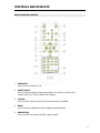
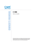
REMOTE CONTROL DEVICE
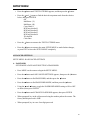
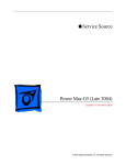
1.
POWER OFF
Press to turn the Cinema 11v off.
2.
ASPECT RATIO
Press to control the picture’s aspect ratio (shape of the screen). It can be 4:3 for
common tube TVs or 16:9 for today’s HDTV displays.
3.
PIP/PBP
Press to control “Picture In Picture” and “Picture By Picture” (PIP/PBP).
4.
MANR
Press to control the MANR level (Motion Adaptive Noise Reduction).
5.
RESOLUTION
Press to control the resolution of HDMI 1 picture output.
13
CONTROLS AND DISPLAYS
6.
NAVIGATION/ENTER
Use the four navigation buttons () to move through the menu options on the
Cinema 11v display. Press ENTER in the center to confirm selections. You can also use the
front panel navigation buttons.
7.
EXIT
Press to leave the SETUP MENU.
8.
MENU
Shows the SETUP MENU on the Cinema 11v display, if active.
9.
INPUT SELECTOR (VIDEO & S-VIDEO)
Use to select the Video or S-Video source.
10. INPUT SELECTOR (HDMI)
Use to select the HDMI source.
11. INPUT SELECTOR (COMPONENT)
Use to select the COMPONENT source.
12. MUTE
Press to mute the main volume.
13. INPUT SELECTOR (RGBHV)
Use to select the RGBHV source.
14. INFO
Press to display the status information of the input.
15. BRIGHT
Press to change the brightness of the display (Off, Low, Medium, or High).
16. COMB FILTER
Press to select the comb filter.
17. TRUE LIFE
Press to select the level of True Life filter with noise coring.
18. NAVIGATION/TEST
Press the TEST button to select the test patterns picture. Use the four navigation
buttons to move through the test patterns.
19. POWER ON
Press to turn the power on.
14
CONNECTIONS
Determine which of the following configurations best describes your system and follow the
corresponding directions.
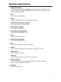
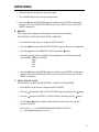
ONE TELEVISION OR MONITOR WITH AN HDMI INPUT
•
•
Using an HDMI cable, connect the television or monitor directly to the HDMI 1 output of
Cinema 11v.
Change the PRE-SET of EDID in Cinema 11v from HDMI 2 to HDMI 1.
If this is not changed, there will be no sound to the television. Read more about this in
the Sound Options section of the manual.
15
CONNECTIONS
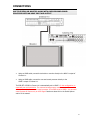
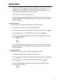
ONE TELEVISION OR MONITOR ALONG WITH ONE SURROUND SOUND
PROCESSOR WITH AN HDMI INPUT AND OUTPUT
•
Using an HDMI cable, connect the television or monitor directly to the HDMI 1 output of
Cinema 11v.
•
Using an HDMI cable, connect the surround sound processor directly to the
HDMI 2 output of Cinema 11v.
The PRE-SET of EDID in Cinema 11v is automatically set to HDMI 2. In this configuration, no
sound will pass to the television. The surround sound processor must be on, and then sound
will be processed by the surround sound processor. If the EDID is set to HDMI 1, the surround
sound process will receive only an LPCM signal. Read more about this in the Sound Options
section of the manual.
16
CONNECTIONS
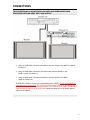
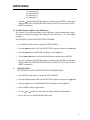
TWO TELEVISIONS OR MONITORS ALONG WITH ONE SURROUND SOUND
PROCESSOR WITH AN HDMI INPUT AND OUTPUT
•
Using an HDMI cable, connect the television or monitor directly to the HDMI 1 output of
Cinema 11v.
•
Using an HDMI cable, connect the surround sound processor directly to the
HDMI 2 output of Cinema 11v.
•
Using an HDMI cable, connect the television or monitor directly to the HDMI
output of Cinema 11a.
The PRE-SET of EDID in Cinema 11v is automatically set to HDMI 2. In this configuration, no
sound will pass to the television. The surround sound processor must be on, and then sound
will be processed by the surround sound processor. If the EDID is set to HDMI 1, the surround
sound process will receive only an LPCM signal. Read more about this in the Sound Options
section of the manual.
17
CONNECTIONS
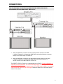
TWO TELEVISIONS OR MONITORS ALONG WITH TWO SURROUND SOUND
PROCESSORS WITH AN HDMI INPUT AND OUTPUT
•
Using an HDMI cable, connect a surround sound processor directly to the HDMI
1 output of Cinema 11v. Using another HDMI cable, connect the television or monitor
directly to the HDMI output of Cinema 11a.
•
Using an HDMI cable, connect the surround sound processor directly to the HDMI
2 output of Cinema 11v. Using another HDMI cable, connect the television or
monitor directly to the HDMI output of Cinema 11a.
The PRE-SET of EDID in Cinema 11v is automatically set to HDMI 2. In this configuration, no
sound will pass to the television. The surround sound processor must be on, and then sound
will be processed by the surround sound processor. If the EDID is set to HDMI 1, the surround
sound process will receive only an LPCM signal. Read more about this in the Sound Options
section of the manual.
18
SETUP MENU
INPUT SELECTION
SETUP MENU INPUT SELECT
To select the input signal of connected video and audio devices, follow these steps:
•
Press MENU on the remote to begin the SETUP MENU.
•
Press the button until INPUT SELECT appears, then press ENTER.
•
Press the button to make a selection, then press ENTER.
•
After selecting the input signal, press the button and select RETURN followed by
ENTER to go to the previous SETUP MENU and continue through the system setup
process. (Press EXIT to leave the SETUP MENU completely.)
INPUT ASSIGNMENT
SETUP MENU INPUT ASSIGN
There are various input sources--HDMI 1, HDMI 2, HDMI 3, HDMI 4, HDMI 5, HDMI
6, COMPONENT 1, CONPONENT 2, RGB, Input 1, Input 2, Input 3, Input 4, Input 5, Input 6,
Input 7, and Input 8. To match the output of connected video and audio devices as well as the
input jacks, use these four functions:
A. CHANGE INPUT NAMES
SETUP MENU INPUT ASSIGN CHANGE INPUT NAMES
The name of a selected input may be customized with up to twelve characters. For
example, INPUT 2 may be modified to read DVD 7 or DVD 8.
•
Press MENU on the remote to begin with the SETUP MENU.
•
Press the button until INPUT ASSIGN appears, then press ENTER.
•
Press the button to select an INPUT CHANNEL, then press ENTER.
•
Press ENTER again to select the input channel, then the INPUT CHANNEL
menu will appear.
•
Scroll to CHANGE INPUT NAMES and press ENTER. The cursor will automatically
appear beneath the first character in the current input name.
19
SETUP MENU
•
Use the and buttons to scroll through the different characters above the
cursor. The following characters are available:
0123456789: ;<=>?@ABCDEFGHIJKLMNOPQRSTUVWXYZ
[\]-_\ abcdefghijklmnopqrstuvwxyz{|}-_
•
After scrolling to the desired character, use the button to advance to the next
character space. The cursor will automatically wrap to the first character space of the
modified title following the last (eighth) character.
•
Use the button on the remote to return to the previous character space.
•
Press ENTER on the remote to save the custom input name.
•
Use the button to scroll to RETURN to view other input channels.
•
Press the button to select another input channel.
•
After changing the input names for all of the inputs in your system, press the button
to select RETURN, and then press ENTER to go to the previous SETUP MENU and
continue through the system setup process. (Press EXIT to leave the SETUP MENU
completely.)
B. ASSIGN VIDEO INPUTS
SETUP MENU INPUT ASSIGN ASSIGNED VIDEO INPUTS
•
Press MENU on the remote to begin the SETUP MENU.
•
Press thebutton until the INPUT ASSIGN menu is displayed, and then press
ENTER.
•
Press the button to select an INPUT CHANNEL, then press ENTER.
•
Press the button to select VIDEO, and then press thebutton.
•
Scroll with the
•
Press ENTER to confirm the video assign.
•
Press thebutton to return to the INPUT CHANNEL .
•
Press the button until RETURN appears, then repeat these steps for other input
channels.
button and button to select the desired video input.
20
SETUP MENU
•
After assigning all of the video inputs, press thebutton to select RETURN, and then
press ENTER to go back to the previous SETUP MENU to continue through the system
setup process. (Press EXIT to leave the SETUP MENU completely.)
C. ASSIGN AUDIO INPUTS
SETUP MENU INPUT ASSIGN ASSIGNED AUDIO INPUTS
•
Press MENU on the remote to use the SETUP MENU.
•
Press thebutton until INPUT ASSIGN appears, then press the ENTER.
•
Press the
•
Press the button to select AUDIO ASSIGN, and then press the
•
Press the button and button to find the desired type of audio input, then press
ENTER.
•
Press the button on the remote to return to INPUT CHANNEL.
•
Press the button until RETURN appears; this will display the other input channel
choices.
•
Press the button until RETURN appears, then repeat these steps for other input
channels.
•
After setting all of the audio inputs, press the button to select RETURN, and then press
ENTER to go back to the previous SETUP MENU to continue through the system setup
process. (Press EXIT to leave the SETUP MENU completely.)
button to select an INPUT CHANNEL, then press ENTER.
D. PICTURE CONTROL
SETUP MENU INPUT ASSIGN
button.
PICTURE CONTROL
•
Press MENU on the remote to begin the SETUP MENU.
•
Press thebutton until the INPUT ASSIGN menu is displayed, then press thebutton.
•
Press the button to select INPUT CHANNELS, and then press ENTER.
•
Press the buttons to select the PICTURE CONTROL menu and press ENTER.
PICTURE CONTROL menu options are as follows:
Brightness – Video brightness controls work by changing the level of the black. The
Brightness control is complimentary to the contrast control. The settings for this control
are –50 to +50. The default setting is 0.
21
SETUP MENU
Contrast – Video Contrast works by adjusting the level of white. Contrast is
complimentary to the Brightness control. The settings for this control are –50 to
+50. The default setting is 0.
Saturation – Saturation refers to the mix of “color” vs. “brightness” in the
picture. Increasing the Saturation makes colors more vivid. Decreasing the
Saturation makes colors look washed out. Changes to either Brightness or
Contrast can change the Saturation. This control can be used to balance the mix of color
vs. brightness. The settings for this control are –50 to +50. The default setting is 0.
Sharpness – Adjusts the “crispness” of the image on the screen. The settings for this
control are –12 to +12. The default setting is 0.
Hue – Adjustment that shifts the shade of color. Sometimes Hue is called tint.
This color control changes color without changing Luminance (picture brightness) or color
saturation. The settings for this control are –50 to +50. The default setting is 0.
Red Gain - Adjusts the red color level. The settings for this control are –50 to
+50. The default setting is 0.
Green Gain - Adjusts the green color level. The settings for this control are –50 to
+50. The default setting is 0.
Blue Gain - Adjusts the blue color level. The settings for this control are –50 to
+50. The default setting is 0.
Gamma – Gamma control adjusts the picture gray level. The settings for this control
are 0 to 5. The default setting is 5.
Use thebutton to navigate to the desired option, then press ENTER; change the settings
to the desired levels. For illustration purposes, these instructions will continue with the
BRIGHTNESS option, but the steps are the same for all of the PICTURE CONTROL menu
options.
•
Press thebutton to find the BRIGHTNESS setting menu.
•
Use the
•
Press the button to return to the BRIGHTNESS setting menu.
•
Press the button to find RETURN, and then press ENTER to go back to the
PICTURE CONTROL menu.
•
Repeat this process to adjust settings as desired. After the adjustments are made, press
the button to find RETURN, then press ENTER to go to the SETUP MENU and
continue the system setup process. (Press EXIT to leave the SETUP MENU completely.)
and buttons to adjust the level of brightness.
22
SETUP MENU
OUTPUT 1 SETUP
SETUP MENU OUTPUT 1 SETUP
A RESOLUTION
Resolution is the pixel density of the display. It is based on the physical number of
columns and rows of pixels creating the display, e.g. 1920 x 1080
SETUP MENU OUTPUT 1 SETUP RESOLUTION
•
Press MENU on the remote to begin the SETUP MENU.
•
Press the button until OUTPUT 1 SETUP appears, then press ENTER.
•
Press the button to highlight RESOLUTION, then press the button.
•
Press the and buttons to find the desired resolution mode from the choices
below, then press ENTER:
Auto
480/576p
720p
1080i
1080p
1080p 24Hz
640 x 480
800 x 600
1024 x 768
1280 x 1024
•
Press the button to return to the OUTPUT 1 SETUP menu to make further
changes, or press EXIT to leave the SETUP MENU completely.
B. ASPECT RATIO
Aspect Ratio is the ratio between the vertical and horizontal dimension of the display.
Standard TV is 4:3, while widescreen is usually 16:9 or larger.
SETUP MENU OUTPUT 1 SETUP ASPECT RATIO
•
Press MENU on the remote to begin the SETUP MENU.
•
Press the button until OUTPUT 1 SETUP appears, then press the ENTER.
•
Press the button to find ASPECT RATIO, and then press the button.
•
Press the button to find the desired aspect ratio from the choices below, then
press ENTER:
23
SETUP MENU
Display
Screen
Shift
•
Press the button again to select DISPLAY ASPECT RATIO
•
Press the and buttons to find the desired display from the choices below,
then press ENTER:
4:3
5:4
16:9
2.35:1
User
•
Press the button to return to the ASPECT RATIO menu.
•
To go back to the ASPECT RATIO menu, press the button until RETURN
appears, then press ENTER. (Press EXIT to leave the SETUP MENU
completely.)
•
Press the button until SCREEN appears, then press the button.
•
Press the and buttons to find the desired screen mode from the choices
below, then press ENTER :
1.25:1
1.33:1
1.78:1
2.35:1
User
•
To go back to the ASPECT RATIO menu, press the button until RETURN
appears, then press ENTER. (Press EXIT to leave the SETUP MENU completely.)
•
Press the button until SHIFT appears, then press the button.
•
Press the button until HOR appears, then press ENTER.
•
Use the and buttons to adjust the horizontal level; press ENTER to confirm
the selection.
•
Press the button to return to the HOR menu.
•
Press the button until VER appears, then press the button.
•
Use the and buttons to adjust the vertical level; press ENTER to confirm the
selection
24
SETUP MENU
•
Press the button to return to the VER menu. (Press EXIT to leave the SETUP
MENU completely.)
C. COLOR SPACE
The color space parameter sets the color space of the output format.
SETUP MENU OUTPUT 1 SETUP COLOR SPACE
•
Press MENU on the remote to begin the SETUP MENU.
•
Press the button until OUTPUT 1 SETUP appears, then press ENTER.
•
Press the button to find COLOR SPACE, and then press the button.
•
Press the and buttons to find the desired color space mode from the choices
below, then press ENTER:
Auto
Y Cb Cr 4: 2: 2
Y Cb Cr 4: 4: 4
RGB (PC) 0-255
•
Press the button to return to the COLOR SPACE menu.
•
Press the button to return to the OUTPUT 1 SETUP menu to make further
changes, or press EXIT to leave the SETUP MENU completely.
OUTPUT 2 SETUP
SETUP MENU OUTPUT 2 SETUP
To adjust the settings of the HDMI 2 output, follow the instructions above for the
OUTPUT 1 SETUP, but select OUTPUT 2 SETUP instead of OUTPUT 1 SETUP where
appropriate.
TEST PATTERNS
SETUP MENU TEST PATTERNS
This menu uses the TEST PATTERNS to test or set the picture of television or monitor.
•
Press MENU on the remote to begin the SETUP MENU.
25
SETUP MENU
•
Press the button until TEST PATTERNS appears, and then press the button.
•
Press the and buttons to find the desired test pattern mode from the choices
below, then press ENTER
Off
Multiburst (V)
Multiburst (H)
Cross Hatch 1
B/W long checked 1
B/W long checked 2
B/W long checked 3
B/W long checked 4
3D checked
Color Bars
•
Press the button to return to the TEST PATTERNS menu.
•
Press the button to return to the main SETUP MENU to make further changes,
or press EXIT to leave the SETUP MENU completely.
ADVANCED SETTINGS
SETUP MENU ADVANCED SETTINGS
A. PASSWORD
SETUP MENU ADVANCED SETTING PASSWORD
•
Press MENU on the remote to begin the SETUP MENU.
•
Press the button until ADVANCED SETTINGS appears, then press the button.
•
Press the button to find PASSWORD, and then press the button.
•
Press the button to find PASSWORD MODE, and then press the button.
•
Using the and buttons, toggle the PASSWORD MODE setting to ON or OFF
as desired, then press ENTER.
•
Press the button until CHANGE PASSWORD appears, then press ENTER.
•
When prompted, key in the old password using the number pad on the remote. The
factory default password is 1111.
•
When prompted, key in a new four-digit password.
26
SETUP MENU
•
When prompted, enter that new password again.
•
The PASSWORD menu will return automatically.
•
Press the button until RETURN appears, and then press ENTER to make more
changes in the ADVANCED SETTING menu. (Press EXIT to leave the SETUP
MENU completely.)
B. BRIGHT
This setting allows changes to the brightness of the front panel display.
SETUP MENU ADVANCED SETTING BRIGHT
•
Press MENU on the remote to begin the SETUP MENU.
•
Press the button until ADVANCED SETTING appears, then press the button.
•
Press the button to find BRIGHT, and then press the button.
•
Press the and buttons to find the desired brightness of the display from the
choices below, then press ENTER:
High
Mid
Low
Off
•
Press the button until RETURN appears, and then press ENTER to make more
changes in the ADVANCED SETTING menu. (Press EXIT to leave the SETUP
MENU completely.)
C. EDIT CUSTOM NAME
SETUP MENU ADVANCED SETTING EDIT CUSTOM NAME
•
Press MENU on the remote to begin the SETUP MENU.
•
Press the button until ADVANCED SETTING appears, then press the button.
•
Press the button to find EDIT CUSTOM NAME, and then press the button.
•
Use the and buttons to find the desired character from the choices below,
then press ENTER:
0123456789: ;<=>?@ABCDEFGHIJKLMNOPQRSTUVWXYZ
[\]-_\ abcdefghijklmnopqrstuvwxyz{|}-_
27
SETUP MENU
•
After the desired character is displayed, use the button to advance to the next
character space. Use the button on the remote to return to the previous
character space. The cursor will automatically wrap to the first character space
when the last (eighteenth) character space is passed.
•
Press ENTER to store the custom input name.
•
Press the button until RETURN appears, and then press ENTER to make more
changes in the ADVANCED SETTING menu. (Press EXIT to leave the SETUP
MENU completely.)
D. IR CONTROLS
SETUP MENU ADVANCED SETTINGS IR CONTROLS
•
Press MENU on the remote to begin the SETUP MENU.
•
Press the button until ADVANCED SETTING appears, then press the button.
•
Press the button to find IR CONTROLS, and then press the button.
•
Press the and buttons to find the desired IR control mode from the choices
below, then press ENTER:
Front
Rear
Both
•
Press the button until RETURN appears, and then press ENTER to make more
changes in the ADVANCED SETTING menu. (Press EXIT to leave the SETUP
MENU completely.)
E. REAR IR MODE
SETUP MENU ADVANCED SETTING REAR IR MODE
•
Press MENU on the remote to begin the SETUP MENU.
•
Press the button until ADVANCED SETTING appears, then press the button.
•
Press the button to find REAR IR MODE, and then press the button.
•
Press the and buttons to find the desired rear IR mode from the choices
below, then press ENTER:
Normal
Invert
28
SETUP MENU
•
Press the button until RETURN appears, and then press ENTER to make more
changes in the ADVANCED SETTING menu. (Press EXIT to leave the SETUP
MENU completely.)
F. ZOOM
The zoom function zooms in on or magnifies the image on your display.
SETUP MENU ADVANCED SETTING ZOOM
•
Press MENU on the remote to begin the SETUP MENU.
•
Press the button until ADVANCED SETTING appears, then press the button.
•
Press the button to find ZOOM, and then press the button.
•
Use the and buttons to select the picture zoom size, and then press ENTER.
•
Press the button until RETURN appears, and then press ENTER to make more
changes in the ADVANCED SETTING menu. (Press EXIT to leave the SETUP
MENU completely.)
G. TRIGGER
SETUP MENU ADVANCED SETTING TRIGGER
•
Press MENU on the remote to begin the SETUP MENU.
•
Press the button until ADVANCED SETTING appears, then press the button.
•
Press the button to find TRIGGER, and then press the button.
•
Press the and buttons to find the desired trigger output port from the choices
below, then press ENTER:
1
2
1&2
•
Press the button until RETURN appears, and then press ENTER to make more
changes in the ADVANCED SETTING menu. (Press EXIT to leave the SETUP
MENU completely.)
H. PICTURE-IN-PICTURE (PIP) & PICTURE-BY-PICTURE (PBP)
SETUP MENU ADVANCED SETTING PIP – PBP
29
SETUP MENU
•
Press MENU on the remote to begin the SETUP MENU.
•
Press the button until ADVANCED SETTING appears, and then press the
button.
•
Press the button to find PIP - PBP, and then press the button.
•
Press the and buttons to find the desired input of sub picture, and then press
ENTER.
•
Press the button until RETURN appears, and then press ENTER to make more
changes in the ADVANCED SETTING menu. (Press EXIT to leave the SETUP
MENU completely.)
•
NOTE: Sub Picture cannot be set to another HDMI input if the main picture
source is also an HDMI input.
I. 3D COMB FILTER
SETUP MENU ADVANCED SETTING 3D COMB FILTER
•
Press MENU on the remote to begin the SETUP MENU.
•
Press the button until ADVANCED SETTING appears, then press the button.
•
Press the button to find 3D COMB FILTER, and then press the button.
•
Using the and buttons, toggle the 3D comb filter setting to ON or OFF as
desired, then press ENTER.
•
Press the button until RETURN appears, and then press ENTER to make more
changes in the ADVANCED SETTING menu. (Press EXIT to leave the SETUP
MENU completely.)
J. TRUE LIFE
SETUP MENU ADVANCED SETTING TRUE LIFE
•
Press MENU on the remote to begin the SETUP MENU.
•
Press the button until ADVANCED SETTING appears, then press the button.
•
Press the button to find TRUE LIFE, and then press the button.
•
Press the and buttons to find the desired true life mode from the choices
below, and then press ENTER:
30
SETUP MENU
No linear thresh 1
No linear thresh 2
No linear gain 1
No linear gain 2
•
Press the button until RETURN appears, and then press ENTER to make more
changes in the ADVANCED SETTING menu. (Press EXIT to leave the SETUP
MENU completely.)
K. MANR (Motion Adaptive Noise Reduction)
The Cinema 11v has motion adaptive noise reduction to reduce random noise along
the edges of compressed images. The settings for this control are 0 – 64. The default
setting is 3.
SETUP MENU ADVANCED SETTING MANR
•
Press MENU on the remote to begin the SETUP MENU.
•
Press the button until ADVANCED SETTING appears, then press the button.
•
Press the button to find MANR, and then press the button.
•
Use the and buttons to select the MANR mode, and then press ENTER.
•
Press the button until RETURN appears, and then press ENTER to make more
changes in the ADVANCED SETTING menu. (Press EXIT to leave the SETUP
MENU completely.)
L.
INFORMATION
SETUP MENU ADVANCED SETTING INFORMATION
•
Press MENU on the remote to begin the SETUP MENU.
•
Press the button until ADVANCED SETTING appears, then press the button.
•
Press the button to find INFORMATION, and then press the button.
•
Press ENTER to display input status.
•
Use the and buttons on the remote to display additional information.
•
Press EXIT to leave the INFORMATION menu.
31
SETUP MENU
M. UPDATE
SETUP MENU ADVANCED SETTING UPDATE
•
Press MENU on the remote to begin the SETUP MENU.
•
Press the button until ADVANCED SETTING appears, then press the button.
•
Press the button to find UPDATE, and then press the button.
•
Use the and buttons to find the desired chipset to use with the FW update
from the choices below, then press ENTER:
ARM
GENS
•
When the FW update is complete, unplug the power cable to turn off the Cinema
11v.
N. EDID CHANNEL
EDID stands for Extended Display Information Data. EDID data exchange is a
standardized means for a display to communicate its capabilities to a source device
( such as the Cinema 11a and Cinema 11v ). The premise of this communication is
for the display to relay its operational characteristics, such as native resolution, to
the attached source, and then allow the source to generate the necessary video
characteristics to match the needs of the display. This maximizes
the functional compatibility between devices without requiring a user to configure
them manually, thus reducing the potential for incorrect settings and adjustments
that could compromise the quality of the displayed images and overall reliability of
the system.
As an example, when a DVD player is powered on, it reads the EDID from an
attached HDTV. The HDTV will have in its EDID contents that it is a Samsung
17" LCD panel that supports a native resolution of 1280x1024 pixels, but can also
support 480p, 720p, and 1080i video modes. The EDID may also say that the TV
is a HDMI device and has two speakers. The DVD player would compare this
information with what it can put out of the HDMI port, then set itself to send
1080i with two channel stereo to the HDTV.
Within the HDMI format, there is a video EDID and an audio EDID. Since the
Cinema 11v has two separate HDMI outputs, the user must choose which HDMI
output will be used as the EDID output. For example, if you connect the Cinema
11v to the Cinema 11a ( or to any audio/video processor ) by HDMI 2, then the
EDID must be set to HDMI 2. This setting will allow the video and audio to pass
the signals. Please also see the CONNECTIONS section of this manual for more
information on connection configurations and the EDID channel.
32
SETUP MENU
See below for instructions on changing the EDID channel. The default setting is HDMI
output 2.
SETUP MENU ADVANCED SETTING EDID CHANNEL
Also refer to the SOUND OPTIONS section of this manual.
•
Press MENU on the remote to begin the SETUP MENU.
•
Press the button until ADVANCED SETTING appears, then press the button.
•
Press the button to find EDID CHANNEL, and then press the button.
•
Use the and buttons to find the desired EDID audio data mode from the
choices below, then press ENTER:
HDMI 1
HDMI 2
•
Press the button until RETURN appears, and then either press ENTER to go
back to the ADVANCE SETTING menu or press EXIT to leave the SETUP
MENU completely.
RESTORE DEFAULT
SETUP MENU RESTORE DEFAULT
•
Press MENU on the remote to begin the SETUP MENU.
•
Press the button until RESTORE DEFAULT appears, then press the button.
•
Press the button to find RESTORE DEFAULT, then press ENTER.
•
Use the and buttons to confirm (yes or no) whether you want to restore the
default settings, and then press ENTER.
•
Press EXIT to leave the SETUP MENU.
EXIT MENU
SETUP MENU EXIT MENU
•
•
Press MENU on the remote to begin the SETUP MENU.
Press the button until EXIT MENU appears, and then press ENTER to leave the
SETUP MENU.
33
SOUND OPTIONS
These options apply only when the HDMI 1 video output of the Cinema 11v is connected
to the main video display while the HDMI 2 video output is connected to the main HDMI
audio input of the surround sound processor as suggested in the CONNECTIONS section
of this manual. Also, please refer to the EDID channel section of Advanced Settings for
more explanation of the EDID function.
SOUND THROUGH A TELEVISION
•
EDID of the Cinema 11v is preset to HDMI 2. Change the EDID to HDMI 1 to
allow sound to pass to the television.
•
Make sure surround sound processor is turned off.
SOUND THROUGH A SURROUND SOUND PROCESSOR
•
Be sure the EDID is set to HDMI 2.
•
Turn on the surround sound processor. In this mode, no sound will pass to the
television.
RESTORING SOUND TO A TELEVISION
•
Mute or turn down the sound on the surround sound processor.
•
Set the EDID back to HDMI 1.
•
Select a new video input on the Cinema 11v, if desired.
•
Turn off the surround sound processor.
Please Note: IF EDID is set to HDMI 1 as required for television sound while the
surround sound processor is turned on, the surround sound processor will receive an
LPCM signal and may cause extraneous noise through the surround sound speakers. To
avoid this, either set the EDID to HDMI 2 prior to turning on the surround sound
processor or set the surround sound processor input to receive an LPCM signal.
34
SERVICE AND CARE
CARE AND CLEANING
Unplug the unit from the wall outlet. Clean the cabinet housing and front panel of the
Cinema 11v with a soft cloth and a glass cleaner. The frequency of cleaning will vary
based on the cleanliness of the environment and the number of hours the Cinema 11v is
operated.
FACTORY SERVICE
Careful consideration has been given to the design of the Cinema 11v to minimize
maintenance issues. Any problems or requests for service should be referred to the
Customer Service Department at 919.355.0010. Do not return the Cinema 11v to the
factory without a return authorization number (RA). Refer to the next section for details
about returning equipment to Cary Audio Design.
Should the unit be lost or damaged in shipment, Cary Audio Design will assume no
responsibility if the shipping company refuses to pay for damage due to improper packing
or lack of insurance. Please use the original carton for shipping the Cinema 11v.
NON-WARRANTY REPAIRS
Cary Audio Design will provide repair service for its products charging on a time and
expense basis. Please call Cary Audio Design at 919.355.0010 for more information
about out-of-warranty service and repair fees
CAUTION:
Never remove or insert the back panel AC plug when the unit is on or
the AC cord is plugged into the wall.
35
LIMITED WARRANTY
Cary Audio Warrants to the original United States purchaser for use in the United
States the Following Cary Audio Products for the Periods Indicated:
1. Power Amplifiers, Integrated Amplifiers, Surround Sound Processors, and Preamplifiers have
a three (3) year parts and labor warranty from the date of the original purchase from Cary
Audio.
2. CD or SACD players, DVD players, or Music Servers have an eighteen (18) month parts and
labor warranty from the date of the original purchase from Cary Audio.
3. Vacuum tubes, if any are used in the component, are offered a 90-day exchange policy
against defects with the exception of the CAVT 300B vacuum tube that has a one (1) year
exchange policy from the date of the original purchase from Cary Audio.
What is Covered and What is Not Covered
Except as specified below, this warranty covers parts and labor to correct all defects in materials
and workmanship. The following are not covered by the warranty:
1. Damage, deterioration, malfunction or failure to meet performance specifications resulting
from:
a. Accident, acts of nature, misuse, abuse, neglect or unauthorized product
modifications
b. Improper installation, removal or maintenance, or failure to follow instructions
supplied with the product.
c. Repair or attempted repair by anyone not authorized by Cary Audio to repair the
product.
d. Any shipment of the product (claims must be presented to the carrier).
e. Any cause other than a product defect.
2. Cleaning, initial set-up, check-ups with no defects found, or charges incurred for installation,
removal or reinstallation of the product.
3. Any product, on which the serial number has been defaced, modified or removed.
4. Batteries.
5. Accessories, including but not limited to, batteries, cables, mounting hardware and brackets,
cleaning accessories, antenna and detachable power cords.
6. Warranty is void if purchase was made from anyone other than an authorized Cary Audio
dealer.
Who May Enforce the Warranty?
This warranty extends to products purchased directly from Cary Audio or an authorized Cary Audio
dealer. Purchasers should inquire of the dealer regarding the nature and extent of the dealer’s
warranty, if any.
To obtain such warranty service, the original purchaser must complete and send in the Warranty
Registration Card within 15 days of purchase.
36
LIMITED WARRANTY
What Will We Pay For?
We will pay for all labor and material expenses for items covered by the warranty. Payment of
shipping charges is discussed in the next section of this warranty.
How You Can Get Service?
In the event that the owner needs to return the unit to Cary Audio for service or repair of a
possible defect, he must follow the following steps:
1. Contact Cary Audio at 919-355-0010 to obtain a Return Merchandise Authorization (RMA)
number prior to shipping; include this number with the package
2. Submit a copy of the original sales receipt; blank receipts will not validate the limited
warranty for service by Cary Audio. The original sales receipt must contain the following
information:
a. The authorized Cary Audio dealer’s name
b. The date of purchase
c. The unit’s sales price
d. The buyer’s name and address
e. Describe in detail the problem.
f. Note the unit’s model number and serial number.
3. Deliver by either of these methods:
a. With all freight and insurance charges prepaid and in its original packing container
or equivalent, ship the component to Cary Audio, 1020 Goodworth Drive Apex, NC
27539.
b. Hand-deliver the product to Cary Audio (address noted above) or the nearest
authorized service facility.
Limitation of Implied Warranties
All implied warranties, including warranties of merchantability and fitness for particular purchase,
are limited in duration to the length of this warranty.
Exclusion of Damages
Cary Audio’s liability for any defective product is limited to repair or replacement of the product at
Cary Audio’s option. Cary Audio shall not be liable for damage to other products caused by any
defects in Cary Audio products, damages based upon inconvenience or loss of use of the product,
or any other damages, whether incidental, consequential, or otherwise.
37
LIMITED WARRANTY
How State Law Relates to the Warranty
Some states do not allow limitations on how long an implied warranty lasts and/or do not allow the
exclusion or limitation of incidental or consequential damages, so the above limitations or
exclusions may not apply to you.
This warranty gives you specific legal rights, and you may also have other rights which vary from
state to state.
International Purchasers (Export Markets)
Cary Audio warrants its merchandise to purchasers within the United States exclusively for use
within the United States. It provides no other warranties, expressed or implied. If you are living
outside of the United States, please consult your local dealer or distributor to determine the details
of your local warranty.
38
1020 Goodworth Drive, Apex, NC 27539
phone 919-355-0010
fax 919-355-0013
www.caryaudio.com
o o o o o o o o o o o o o o o o o o o o o o o o o
CARY AUDIO DESIGN
o o o o o o o o o o o o o o o o o o o o o o o o o o o o o o o o o o o o o o o o o o o o o o o o o o o o o o o o o o o o o o o o o o o o o o o o o o o o o o o o o o o o o