1
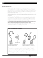
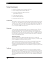
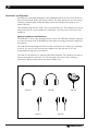
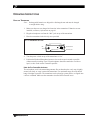
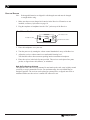
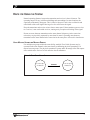
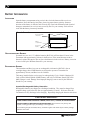
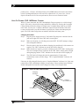
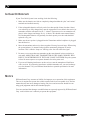
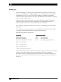
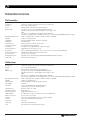
Set Up
Guide & User
Manual
Williams Sound Hearing Helper™
Tour Guide System
Models TGS 173 & TGS 174
Wireless, Portable FM Listening System
Transmitter Models T1-173.400, T1-174.100, T1-174.300, T1-175.500, T1-176.300
Receiver Models R1-173.400, R1-174.100, R1-174.300, R1-175.500, R1-176.300
MAN 106B (ENG)
®
Williams
Sound
Helping People Hear
FM TOUR GUIDE SYSTEM, MODELS TGS 173
INSTALLATION GUIDE & USER MANUAL
Contents
&
TGS 174
Page
SYSTEM OVERVIEW
4
SYSTEM COMPONENTS
5
TRANSMITTER
MICROPHONES
RECEIVER
HEADPHONES & EARPHONES
OPERATING INSTRUCTIONS
7
TRANSMITTER
RECEIVER
HINTS FOR USING THE SYSTEM
BATTERY INFORMATION
10
BATTERY INSTALLATION
RECHARGEABLE & NON-RECHARGEABLE BATTERIES
USING OPTIONAL BATTERY CHARGERS
IN CASE OF DIFFICULTY
12
WARRANTY
13
SYSTEM SPECIFICATIONS
14
Williams
Sound ®
Helping People Hear
3
SYSTEM OVERVIEW
The Hearing Helper® Tour Guide System is a portable, high-performance, wireless system
composed of a transmitter and receivers and designed for use in guided tour applications.
The system allows one-way transmission of a tour guide’s voice to group members using an
FM radio signal. Using the system helps group members overcome background noise and
distance from the person speaking.
The Hearing Helper® System can be used for large or small tour groups and in noisy or quiet
environments.
Your Hearing Helper® Tour Guide System has two principal parts: the transmitter and the
receiver. Much like a miniature radio station, the transmitter and microphone pick up the
sounds you want to hear and broadcast them over an FM radio signal. The receivers and
headphones are used to pick up the broadcast up to 100 meters away.
To avoid difficulties, please read through these instructions as you begin to use the system.
Then save them for questions that arise as you continue to use your system.
If you have problems with the Hearing Helper® Tour Guide System, don’t hesitate to call
your Williams Sound Distributor or our European Sales Office.
FIGURE 1:
HOW THE TOUR GUIDE SYSTEM WORKS
FM Radio Signal
Tour Guide Uses the Body Pack
Transmitter With Microphone
Listeners use Personal Receivers with
Earphones, Headphones, Or Neckloop
The tour guide wears the body-pack transmitter and headset microphone. The guide’s
voice is broadcast as an FM radio signal over a distance of up to 30 meters. Listeners use
the pocket receiver and headphone to hear the speaker’s voice directly, with reduced
background noise. A neckloop telecoil coupler allows the system to be used with telecoil
(T-Switch) equipped hearing aids, at somewhat reduced range.
4
Williams
Sound ®
Helping People Hear
SYSTEM COMPONENTS
Body Pack Transmitter with (2) AA batteries (BAT 001)
Noise-cancelling headset microphone (MIC 044)
(6) Personal FM Receivers w/batteries (BAT 001)
and headphones (HED 021)
(7) Belt clip cases (CCS 001)
Instruction Manual (MAN 106)
System carry case (CCS 030 S)
THE TRANSMITTER
The transmitter is a battery-powered body-pack model used with a microphone to pick up the
tour guide's voice. The transmitter produces an FM radio signal to broadcast the tour guide's
voice to the receiver units. A simple slide switch on top of the transmitter turns the unit on or
off. The transmitter operates on two AA non-rechargeable alkaline batteries (BAT 001), or
two AA rechargeable NiMH batteries (BAT 026).
MICROPHONES
A noise-cancelling, headset microphone (MIC 044) is the standard microphone. The noisecancelling microphone helps to reduce background sounds in noisy environments. The
microphone plugs into the “MIC” jack on top of the Transmitter. The microphone should be
positioned directly in front of the tour guide's mouth for to achieve an optimal signal to noise
ratio and so that head movement does not affect the loudness of the signal. The microphone
cord acts as the transmitting antenna.
Optional Microphones
An optional Hearing Protector Headset Microphone (MIC 036) is also available for
extremely high noise environments. It features ear muffs that completely cover both ears and
provides 24 dB NRR of attenuation for hearing protection.
An optional Lapel Clip Microphone can be used in quieter environments like museums or
galleries. The MIC 050 has an omnidirectional pick-up pattern. The MIC 056 has a
directional (or cardioid) pick-up pattern, which will reduce background noise somewhat.
A small hand-held microphone (MIC 026) is also available for tour guides who prefer to hold
the microphone.
THE RECEIVER
The receiver is a battery-powered body-pack receiver used with a headphone to hear the
signal produced by the transmitter. The receiver is pre-tuned to the transmitter and has a useradjustable volume control. The headphone plugs into the “EAR” jack on top of the Receiver.
The receiver is turned on by rotating the volume control wheel. The receiver operates on two
AA non-rechargeable alkaline batteries (BAT 001), or two AA rechargeable NiMH batteries
(BAT 026).
Williams
Sound ®
Helping People Hear
5
HEADPHONES AND EARPHONES
The HED 021 Lightweight Headphone is the standard headset for the Tour Guide System. It
offers excellent sound quality and wearing comfort. The foam earpads may be removed and
washed in a mild detergent, rinsed thoroughly, and air dried. Replacement pads are part
number HED 013.
The headphone plugs into the “EAR” jack on top of the Receiver. The headphones are wired
with a mono plug. If a stereo headphone is substituted, it will only work on one side of the
headphone.
Optional Headphones and Earphones
The HED 008 is a heavy-duty, hearing-protector headset. The HED 008 earmuffs completely
cover the ears and provide 24 dB NRR noise attenuation for hearing protection in high noise
environments.
The EAR 022 Surround Earphone offers excellent sound quality in a unique style that hangs
on the ear. It is easy to keep clean since the earphone does not enter the ear. It is not
recommended for high noise environments.
The EAR 013 and EAR 014 are single and dual Mini Earphones. The earbud-style features a
foam covering that fits in the outer ear. The foam pads can be removed for cleaning or
replacement. Replacement pads are part number EAR 015-10.
FIG. 2: EARPHONE / HEADPHONE OPTIONS
HED 021
HED 008
EAR 013
6
EAR 022
EAR 014
Williams
Sound ®
Helping People Hear
OPERATING INSTRUCTIONS
USING THE TRANSMITTER
Note:
Rechargeable batteries are shipped in a discharged state and must be charged
overnight before using.
1. Make sure there are two charged AA batteries in the transmitter. If batteries are not
installed, see Battery Information on page 10.
2. Plug the microphone cord into the “Mic” jack on top of the transmitter.
3. Place the transmitter in the belt clip case provided.
FIG. 2: TRANSMITTER TOP VIEW
Off
Mic
Mic
Jack
On
FM
Williams Sound FM
On/Off Switch
ON Indicator
4. Turn the power switch on top of the transmitter to “On.”
5. Position the Headset Microphone boom as close to the wearer's mouth as possible
without actually touching. Lapel Clip microphones should be attached to a collar or
lapel, as close to the wearer's mouth as possible.
Note On The Transmitter Antenna:
The microphone cord is the transmitting antenna. Do not bunch up the cord, wrap it tightly
around your body, or wrap it around the transmitter. For maximum range, the cord should
hang as straight as possible. The transmitter can be placed in a pants pocket, or clipped onto
a belt or waistband. Make sure the transmitter is turned OFF when not in use.
Williams
Sound ®
Helping People Hear
7
USING THE RECEIVER
Note:
Rechargeable batteries are shipped in a discharged state and must be charged
overnight before using.
1. Make sure there are two charged AA batteries in the Receiver. If batteries are not
installed, see Battery Information on page 10.
2. Plug the earphone or headphone into the “Ear” jack on top of the Receiver.
FIG. 3: RECEIVER TOP VIEW
"On" Indicator LED
EAR
Volume
Headphone Jack
1
On/Off Volume Switch
3. Place the headphones over your ears.
4. Turn the power on by rotating the volume control thumbwheel on top of the Receiver.
5. Adjust the receiver volume control to a comfortable listening level.
You should be able to hear someone speaking into the transmitter microphone.
6. Place the receiver in the belt clip case provided. The receiver can be placed in a pants
pocket, or clipped onto a belt, harness, or waistband.
Note On The Receiver Antenna:
The earphone cord is the receiving antenna. Do not bunch up the cord, wrap it tightly around
your body, or wrap it around the receiver. For maximum range, the cord should hang as
straight as possible. The receiver can be placed in a pants pocket, or clipped onto a belt or
waistband. Make sure the receiver is turned OFF when not in use.
8
Williams
Sound ®
Helping People Hear
HINTS FOR USING THE SYSTEM
Normal operating distance between the transmitter and receiver is about 30 meters. The
operating range will vary in different buildings and surroundings. In some locations, the
signal may momentarily disappear. This is called a “drop-out” and is due to reflection and
cancellation of the radio signal. Moving a few feet will restore the signal.
Keep the transmitter and receiver units at least a meter apart. If the transmitter gets too close
to a receiver, it can overload the receiver, causing noisy reception or blocking of the signal.
Do not use more than one transmitter on the same channel (frequency) at the same time
unless they are physically separated by more than 30 meters. Operating more than one
transmitter on the same channel at the same time in the same place will result in interference.
USING MULTIPLE SYSTEMS FOR MULTIPLE GROUPS:
For multiple tour groups within the same facility, multiple Tour Guide Systems may be
operated on the same channel at the same time by maintaining physical separation of 30
meters between groups. The physical separation of groups takes advantage of the FM capture
effect which causes receivers to lock onto the closest transmitter.
FIGURE 4: TOUR GUIDE GROUP SEPARATION
Tour Group 1
Channel A
Williams
Sound ®
Helping People Hear
30 Meters
Tour Group 2
Channel A
9
BATTERY INFORMATION
INSTALLATION
Open the battery compartment using a coin in the slot in the bottom of the receiver or
transmitter. Press the batteries into place, observing proper battery polarity. Incorrect
insertion of the battery is difficult, and if forced, may cause both mechanical and electrical
damage to transmitters or receivers not covered by the five year warranty. Units will not
work with the battery incorrectly installed.
FIGURE 4: BATTERY INSTALLATION
Rear of Transmitter
or Receiver
Battery
Compartment
Note Proper
Polarity
–
+
+
–
Tab
NON-RECHARGEABLE BATTERIES
In normal use, two AA 1.5 V alkaline batteries (BAT 001) will last about 12 hours in the
Transmitter and approximately 30 hours in the Receiver. If the sound becomes weak or
distorted, replace the batteries. Do not leave dead batteries in the receivers. Battery corrosion
is not covered by the Williams Sound five year warranty.
RECHARGEABLE BATTERIES
The transmitter and Receivers can use rechargeable AA batteries (BAT 026). On an
overnight charge, these NiMH batteries are designed to operate a Transmitter for
approximately 8 hours, and Receivers for 20 hours.
The battery installed in the receiver may be recharged only if it is a Nickel Cadmium (NiCad) or Nickel-Metal Hydride (NiMH) battery, and only if a Williams Sound CHG 1600
Multi-Charger is used. Damage from improper charging is not covered by the Williams
Sound five year warranty.
Important Rechargeable Battery Information
Rechargeable batteries are shipped in a discharged condition. They must be charged for a
complete charge cycle before the first use (approximately 15 hours). It’s best to allow NiCad batteries to fully discharge before charging. Repeatedly charging the batteries after short
!! IMPORTANT WARNINGS !!
DO NOT ATTEMPT TO RECHARGE ZINC CARBON (“HEAVY DUTY”), ALKALINE, OR LITHIUM BATTERIES!
DO NOT ATTEMPT TO RECHARGE DISPOSABLE BATTERIES! These batteries may heat up and
explode, causing possible injury and damage to the equipment.
Avoid shorting the plus and minus battery terminals together with metal objects. Battery damage
and burns can result!
10
Williams
Sound ®
Helping People Hear
periods of use, 1-2 hours, will shorten battery life (NiMH batteries do not have this characteristic). Rechargeable batteries will need to be replaced after 1-2 years of use. Do not
dispose of batteries in fire. Do not open batteries, there are toxic chemicals inside.
USING THE OPTIONAL CHG 1600 BATTERY CHARGER
With AC power connected, the CHG 1600 Multiple Charger operates in a “trickle charge”
mode. Units can be left on trickle charge indefinitely without risk. Pressing the Overnight
Charge button switches the charger to a higher-rate, overnight charge mode on a 15 hour
timer. After 15 hours, the “Complete / Maintain” light will come on and the CHG 1600
reverts to trickle mode. Any time the button is pressed, the 15 hour timed charge begins
again. The CHG 1600 Charger does not monitor individual unit battery state.
Charging Instructions
Step 1:
Plug the power supply into an AC wall outlet. Plug the power connector into the
jack on the right side of the CHG 1600’s control panel.
Step 2:
Make sure the units you will charge are turned OFF. DO NOT attempt to charge
non-rechargeable batteries.
Step 3:
Place the units in the slots so that the charging pins and the unit’s side contacts are
coupled. The “CHG” indicator next to the unit will be dimly lit.
Step 4:
When all units are in place, press the red button on the CHG 1600’s control panel.
The red “Overnight Charge” indicator on the CHG 1600’s control panel will light
during charging, and the “CHG” indicators next to each unit will be brightly lit.
Step 5:
The CHG 1600 will charge the units for approximately 15 hours, then
automatically resume a trickle charge. The “Complete/Maintain” indicator will
come on.
Units may be fully charged before the green “Complete/Maintain” indicator is lit. Units may
remain in the CHG 1600 Multiple Charger for more than 15 hours without harm. Williams
Sound rechargeable AA batteries can be charged on a daily or less frequent basis.
FIGURE 5:
USING THE CHG 1600 CHARGER
Charging
Indicators
Charging
Contact Holes
Charging Pins
Williams
Sound ®
Helping People Hear
11
IN CASE OF DIFFICULTY
If your Tour Guide System is not working, check the following:
1. Make sure the batteries are fresh or completely charged and that the “plus” and “minus”
terminals are installed correctly.
2. If the rechargeable batteries will only work for a short period of time (less than 1 hour)
even after they are fully charged, they must be regenerated. Leave them in the receiver or
transmitter with the unit turned on, for 5 - 6 hours. Then turn receiver or transmitter off,
place it in the charger, and charge for 14 - 16 hours. This should restore normal battery
life. Rechargeable batteries will gradually lose their capacity over time and should be
replaced every year.
3. Make sure the microphone is plugged into the Transmitter and the headphone is plugged
into the Receiver.
4. Move the transmitter and receiver closer together. You may be out of range. When using
the system indoors, it’s normal for the signal to momentarily disappear in certain
locations. This is called a “drop-out.” Moving a few feet will restore the signal.
5. Do not try to use more than one transmitter on the same channel in close proximity to
each other. MORE THAN ONE TRANSMITTER ON THE SAME CHANNEL WILL
RESULT IN INTERFERENCE IF THEY ARE CLOSE TOGETHER. Keep the systems
at least 50 meters apart or use separate channels for each system used.
6. If you are still hearing interference on the receivers, turn the transmitter off and listen
with a receiver. If you hear the interference with the transmitter off, you need to change
to a clear channel. Call your Williams Sound dealer or spanish represenative for more
information.
NOTICE
Williams Sound Corp. assumes no liability for improper use or operation of this equipment.
The user is cautioned to operate the volume controls at the lowest acceptable level, and in a
manner that will not cause damage to hearing. Ear pieces and accessories should be worn
using good judgement and for their intended purpose.
Users are cautioned that changes or modifications not expressly approved by Williams Sound
Corp. could void the user’s authority to operate the equipment
12
Williams
Sound ®
Helping People Hear
WARRANTY
The Williams Sound Tour Guide System is engineered and designed to provide you with
many years of reliable service. Williams Sound warrants it against defects in materials and
workmanship for FIVE (5) years EXCEPT FOR earphones, headphones, rechargeable
batteries, chargers, cables, antennas, carry cases, and all other accessory products. Accessory
products carry a 90 day warranty.
If the product fails within the specified warranty period, Williams Sound will determine
whether to repair or replace the defective equipment. This warranty does not apply to
physical damage, abuse, mis-use, or products that have been modified.
If you experience difficulty with your system, call your local Distributor or our European
Sales Office.
If it is necessary to return the system for service, a Williams Sound representative will give
you a Return Authorization Number (RA) and shipping instructions.
Pack the system carefully and send it to:
U.S. Office
European Sales Office
Williams Sound Corp.
10321 West 70th Street
Eden Prairie, MN 55344-3459 USA
TEL:
FAX:
e-mail:
+34 952 819 069
+34 952 819 021
[email protected]
Phone: 952-943-2252
Fax:
952-943-2174
TTY:
952-943-9675
e-mail: [email protected]
Your warranty becomes effective the date you purchase your system. Your returned warranty
card is our way of knowing when your warranty begins. It also gives us important
information about your system including the serial number. This information will help us
serve you better in the future. Please take a moment to complete and mail the attached card.
Thank you.
Williams
Sound ®
Helping People Hear
13
SYSTEM SPECIFICATIONS
FM Transmitter
Models:
Dimensions:
Weight:
Color:
Battery Type:
Operating Frequencies:
Stability:
Modulation:
RF Output:
Freq Response:
Signal–Noise Ratio:
Compressor:
Transmit Antenna:
Microphone:
Controls & Indicators:
Mic Connector:
Charging Contacts:
Approvals:
T1-173.400, T1-174.100, T1-174.300, T1-175.500, T1-176.300
3-5/8" L x 2-3/8" W x 7/8" H (92.1 mm x 60.3 mm x 22.2 mm)
4.4 oz (125 g) with batteries
Neptune blue, shatter-resistant polypropylene
Two (2) AA 1.5 V Non-rechargeable Alkaline batteries
(BAT 001), 100 mA nominal current drain, 12 hours approx. life
(OR)
Two (2) AA 1.5 V NiMH Rechargeable batteries (BAT 026),
8 hours per charge approx., recharges in 14–16 hours, uses CHG 1600 Multiple Battery Charger
Fixed 173.400 (UK only), 174.100, 174.300, 175.500, 176.300 MHz
± .005%, crystal reference
Narrow-band FM, 10 kHz, 100 µS pre-emphasis
1.5 mW typical
100 Hz to 10 kHz, ± 3 dB at 1% max. THD
55 - 60 dB, with R1-173 Receiver
Compressor uses adjustable slope and noise gate
Integral with 39" microphone cord
Noise-cancelling, Headset type, 39 in. cord, 3.5 mm mono phone plug (MIC 044)
On/Off switch, slide-type; “On” Indicator LED
3.5 mm mono phone jack
Designed for use with CHG 1600 and CHG 200 Multiple Battery Chargers
MPT 1345, ETS 300 422, CE
FM Receiver
Models:
Dimensions:
Weight:
Color:
Battery Type:
Operating Frequencies:
Stability:
FM Deviation:
AFC Range:
Sensitivity:
Freq Response:
Signal–Noise Ratio:
Receive Antenna:
Audio Output:
Output Connector:
Squelch:
Controls:
Indicators:
Approvals:
Note:
14
R1-173.400, R1-174.100, R1-174.300, R1-175.500, R1-176.300
3-5/8" L x 2-3/8" W x 7/8" H (92.1 mm x 60.3 mm x 22.2 mm)
4.6 oz (130 g) with batteries
Neptune blue, shatter-resistant polypropylene
Two (2) AA 1.5 V non-rechargeable Alkaline batteries
(BAT 001), 42 mA nom. current drain, 30 hours approx. life
(OR)
Two (2) AA 1.5 V NiMH rechargeable batteries (BAT 026),
20 hours per charge approx., recharges in 14–16 hours, uses CHG 1600 Multiple Battery Charger
Fixed 173.400 (UK only), 174.100, 174.300, 175.500, 176.300 MHz
± .005%, crystal reference
Narrow-band FM, 10 kHz, 100 µS de-emphasis
± 120 kHz
.5 µV at 12 dB Sinad with squelch defeated,
squelches at 8 µV for min. 50 dB S/N ratio
200 Hz to 10 kHz, +2, –4 dB
60 dB at 10 µV
Integral with earphone cord
35 mW, max. at 16 Ω; for use with 8–32 Ω mono headphones
3.5 mm mono phone jack
Set to turn off audio under weak or no signal condition
Volume: thumbwheel/on/off/volume
“On” LED
MPT 1345, ETS 300 422, CE
Specifications are electrical performance
Williams
Sound ®
Helping People Hear
®
Williams
Sound
Helping People Hear
www.williamssound.com
© 2004, Williams Sound Corp. MAN 106B (ENG)