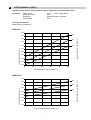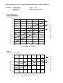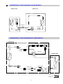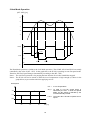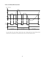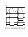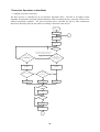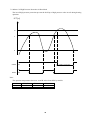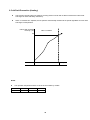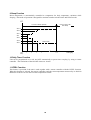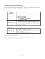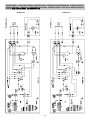
1
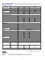
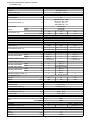
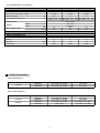
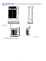
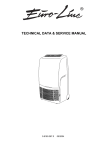
TECHNICAL DATA & SERVICE MANUAL
- AUR101CL
COOLING ONLY VERSION (R407C)
- AUR131CL
- AUR101HL
HEAT PUMP VERSION (R407C)
ROOM AIR CONDITIONER WITH REMOTE CONDENSER
0.8180.237.0
04/2002
Table of Contents
Page
A
SPECIFICATIONS
1) Unit specifications
2) Major Component specifications
3
3
4
B
OPERATING RANGE
5
C
DIMENSIONAL DATA
6
D
PERFORMANCE CHARTS
7
E
REFRIGERANT FLOW DIAGRAM
9
F
FUNCTION
1) Cool Mode Operation
2) Heat Mode Operation
3) Auto Mode Operation
4) Dry Mode Operation
5) Fan Mode Operation
6) Protection Operations in Cool and Dry Modes
7) Protection Operations in Heat Mode
8) Cold Draft Prevention (Heating)
9) Sleep Function
10) Daily Timer Function
11) IFEEL Function
12) Manual Unit Control and Led Indicators
13) Recovery from Power Failure
10
10
11
12
13
13
14
16
19
20
20
20
21
21
G
ELECTRICAL DATA
22
H
TROUBLESHOOTING
24
I
PROCEDURE FOR THE REFRIGERANT CHARGE RESTORING
31
L
CHECKING ELECTRICAL COMPONENTS
33
33
34
34
1) Measurement of Insulation Resistance
2) Checking Continuity of Fuse on PCS Ass'y
3) Checking Motor Capacitor
2
A
SPECIFICATIONS
1) UNIT SPECIFICATIONS
UNIT MODEL
AUR101CL
AUR131CL
Power source
AUR101HL
220 - 240 V ~ 50 Hz
PERFORMANCES
COOLING
BTU / h
Capacity
W
Air circulation (high/med/low)
Moisture removal (high speed)
9045
2650
COOLING
HEATING
12525
9560
10720
3670
2800
3140
m3 / h
370/340/270
450/400/340
370/340/270
l /h
1.2
1.5
1.2
ELECTRICAL RATINGS
220 ÷ 240
Voltage rating
V
Available voltage range
V
Running ampere
A
4.4
6.2
4.2
4.3
Power input
W
980
1300
940
950
Power factor
%
97
91
97
96
W/W
2.70
2.82
2.98
A
23
34
C.O.P.
Compressor locked rotor amperes
198
÷ 264
3.31
23
FEATURES
Controls / temperature control
Microprocessor / I.C. Thermostat
Control unit
Wireless remote control unit
Timer
ON / OFF 24 hours and program
Fan speed indoor / outdoor
3 and auto / 1
Airflow direction
(Indoor)
Horizontal
Manual
Vertical
Manual
Air filter
Washable, easy access
Compressor
Rotary (hermetic)
Refrig./Stand. charge at shipmen
g
910
1220
1030
Tot. refrig. charge with 2 m extension
g
960
1270
1090
Tot. refrig. charge with 4 m extension
1150
Refrigerant control
Capillary tube
Indoor Hi/Me/Lo dB-A
Sound level
Outdoor Hi dB-A
44 / 40 / 39
46 / 42 / 41
44 / 40 / 39
54
51
51
Stand. tubing length
m
~ 2.5
Tubing length with 2 m extension kit
m
~ 4.5
Tubing length with 4 m extension kit
m
~ 6.5
DIMENSIONS AND WEIGHT
Indoor unit
Outdoor unit
Height
UNIT DIMENSIONS
mm
790
Width
mm
580
Depth
mm
245
Height
mm
435
490
490
Width
mm
440
525
525
Depth
mm
Net weight / indoor unit - outdoor unit
kg
230
250
250
44 / 9.5
44 / 15
44 / 15
Data subject to change without notice.
NOTA
Rating conditions:
Cooling:
Heating:
outside air temp.: 35°C DB, indoor unit entering air temp.: 27 °C DB, 19 °C WB
outside air temp.: 7°C DB, 6 °C WB, indoor unit entering air temp.: 20 °C DB
3
2) MAJOR COMPONENT SPECIFICATIONS
a) INDOOR UNIT
MODEL
CONTROLLER P.C.B.
Controls
Control circuit fuse
FAN & FAN MOTOR
Number / Diameter / Lenght
Nominal output
Coil resistance (at 25 °C)
AUR101CL
mm
W
Ω
Safety device
Setting
Open
Close
Run capacitor (C1)
THERMISTOR (COIL SENSOR) TH1
Resistance (at 25 °C)
THERMISTOR (ROOM SENSOR) TH2
Resistance (at 25 °C)
COMPRESSOR (Rotary hermetic)
Nominal output
Compressor oil
Coil resistance (at 20 °C)
°C
°C
µF
VAC
kΩ
kΩ
W
cc
Ω
SAFETY DEVICES
Overload relay (OLR)
Operating temperature
Open
Close
°C
°C
Operating amperes (at 25 °C)
MST20ALU-9201
135 ± 5
69 ± 11
Trip in
6 ÷ 16 s at 19 A
Open
Close
°C
°C
//
//
Open
Close
°C
°C
//
//
Operating amperes (at 25 °C)
Run capacitor (C3)
Capacity
Voltage
CONDENSATE PUMP (PC)
Rating
Nominal output
Coil resistance (at 20 °C)
PUMP RELAY (RP)
Coil rating
Coil resistance (at 20 °C)
Contact rating
FLOAT MICROSWITCH (MS)
Contact rating
Float
SOLENOID VALVE (4 WAY VALVE)
Coil rating
Coil resistance (at 20 °C)
HEAT EXCHANGE COIL
Coil
Rows
Fin pitch
Face area
//
µF
VAC
//
//
22.5
450
25
450
PC 95643
230 V ~ 50 Hz
12 ± 10 %
122 ± 10 %
FINDER 60.62
230 V ~ 50 Hz
7.25 ± 10 %
10 A - 250 V
CROUZET F83161.3
10 (4) A - 250 VAC
Open
Close
//
//
//
//
W
Ω
kΩ
Up
Down
Ω
MST20ALU-9201
135 ± 5
69 ± 11
Trip in
6 ÷ 16 s at 19 A
//
//
CS-7C115
115 ± 4
95 ± 10
MST56ALU-9202
150 ± 5
69 ± 11
Trip in
6 ÷ 16 s at 22.5 A
Overload relay (OLR2)
Operating temperature
AUR101HL
Microprocessor
250 VAC - 3.15 A
Cross flow
1 / ø 100 / L 410
27
GRY-WHT: 545 ÷ 630
WHT-VLT: 92 ÷ 105
VLT-YEL: 62 ÷ 71
GRY-BRN: 78 ÷ 90
Internal type
150 ± 10
Automatic
1.0
1.5
1.0
440
440
440
NTC SENSOR
10 ± 5%
NTC SENSOR
10 ± 5%
80228245B
80235245B
80228245B
950
1290
950
500
550
500
C-R: 3.01 ± 7% C-R: 1.92 ± 7%
C-R: 3.01 ± 7%
C-S: 7.02 ± 7% C-S: 5.29 ± 7%
C-S: 7.02 ± 7%
Overload relay (OLR1)
Operating temperature
AUR131CL
230 V ~ 50 Hz - 6 W
1440 ± 5 %
Aluminium plate fin / Copper tube
2
1.8
0.185
mm
m2
4
22.5
450
b) OUTDOOR UNIT (LITTLE BAG)
MODEL
FAN & FAN MOTOR
Number / Diameter
No of pole / rpm (220 V, high)
Nominal output
Coil resistance (at 25 °C)
Safety device
Open
Close
Setting
Run capacitor (C2)
THERMISTOR (COIL SENSOR) TH3
Resistance (at 25 °C)
HEAT EXCHANGE COIL
Coil
Rows
Fin pitch
Face area
B
AUR101CL
AUR131CL
AUR101HL
Propeller
Propeller
Propeller
mm
1 / ø 320
1 / ø 380
1 / ø 380
4 / 1205
6 / 860
6 / 860
W
58
70
70
BLU-BRN: 249 ÷ 287 BLU-BRN: 218 ÷ 251 BLU-BRN: 218 ÷ 251
Ω
BLU-BLK: 270 ÷ 311 BLU-BLK: 230 ÷ 265 BLU-BLK: 230 ÷ 265
Internal type
°C
150 ± 10
°C
Automatic
µF
2.0
2.5
2.5
VAC
450
450
450
NTC SENSOR
kΩ
10 ± 1%
2
1.6
0.227
mm
m2
Aluminium plate fin / Copper tube
2
1.6
0.290
2
1.6
0.290
OPERATING RANGE
COOLING MODELS
Cooling
Temperature
Maximun
Minimum
Indoor air intake temperature
32 °C DB / 23 °C WB
19 °C DB / 14 °C WB
Outdoor air intake temperature
46 °C DB
19 °C DB
Temperature
Maximun
Minimum
Maximun
Minimum
Indoor air intake temperature
32 °C DB / 23 °C WB
19 °C DB / 14 °C WB
27 °C DB / 19 °C WB
- DB / - WB
Outdoor air intake temperature
46 °C DB
19 °C DB
24 °C DB / 18 °C WB
-8 °C DB / -9 °C WB
HEAT PUMP MODELS
Cooling
Heating
5
C
DIMENSIONAL DATA
Indoor unit
790
835
580
245
245
435 (*
490)
425
Outdoor unit
440
440
(* 490)
230230
(* 250)
DIMENSIONS: mm
* HEAT PUMP MODEL AND AUR131CL
6
PERFORMANCE CHARTS
Operating characteristics versus outdoor ambient temperature and indoor temperature.
Conditions:
Power source
Indoor air velocity
Refrigerant
Tubing length
230 V - 1 - 50Hz - Single phase
High
Amount charged at shipment
2,5 m
Cooling characteristics
Indoor relative humidity 46%
AUR101CL
5.2
32
4.8
27
4.6
OPERATING CURRENT - A
4.4
19
4.2
4.0
3.8
3.6
INDOOR INLET AIR D.B. TEMP. (°C)
5.0
3.4
3.2
20
25
30
35
40
45
OUTDOOR INLET AIR D.B. TEMP. (°C)
AUR131CL
32
6.5
27
6.0
5.5
19
5.0
4.5
4.0
3.5
3.0
20
25
30
35
OUTDOOR INLET AIR D.B. TEMP. (°C)
7
40
45
INDOOR INLET AIR D.B. TEMP. (°C)
7.0
OPERATING CURRENT - A
D
Operating characteristics versus outdoor ambient temperature and indoor temperature.
Conditions:
Power source
Indoor air velocity
Refrigerant
Tubing length
230 V - 1 - 50Hz
High
Amount charged at shipment
2,5 m
HEAT PUMP MODELS
Cooling characteristics
Indoor relative humidity 46%
…
5.0
…
5.2
32
27
4.6
4.4
19
4.0
…
OPERATING CURRENT - A
4.2
3.8
3.6
3.4
INDOOR INLET AIR D.B. TEMP. (°C)
4.8
3.2
3.0
20
25
30
35
40
45
OUTDOOR INLET AIR D.B. TEMP. (°C)
Heating
Outdoor relative humidity 85%
24
5.0
4.5
18
4.0
…
OPERATING CURRENT - A
20
3.5
3.0
-10
-5
0
5
10
15
OUTDOOR INLET AIR D.B. TEMP. (°C)
8
20
25
INDOOR INLET AIR D.B. TEMP. (°C)
…
…
5.5
REFRIGERANT FLOW DIAGRAM COOLING MODELS
Indoor unit
Heat exchanger
Heat exchanger
Mechanical filter
Outdoor unit
CAPILLARY
TUBE
Compressor
Accumulator
QUICK
CONNECTOR
REFRIGERANT FLOW DIAGRAM HEAT PUMP MODELS
Compressor
Indoor unit
Accumulator
Muffler
4-way valve
Heat exchanger
Outdoor unit
Heat exchanger
E
Capillary tube
Capillary tube
(
)
Quick connector
Stainer
Drier
Check
valve
Cooling cycle
Heating cycle
9
F
FUNCTION
1 Cool Mode Operation
(RT - SPT) [ oc]
+3
+2
+1
0
-1
over 3 min
over 5 min
ON
COMP
OFF
ON
OFAN
OFF
over 30 sec
H
IFAN
M
L
ON
RV
OFF
In Cool Mode, the operation of the Compressor (COMP), Outdoor Fan (OFAN) and Indoor Fan (IFAN)
are determined by the difference between the Room Temperature (RT) and the Set Point Temperature
(SPT) as in the graph above.
Notes:
1. In this graph, the IFAN is operating in the “Auto Fan Speed” setting. If the user has selected the low,
medium or high fan speed, the IFAN will run constantly at that speed only.
2. In addition to the value of (RT-SPT), the operations of the relays are also controlled by protection
delays. For example, (a) the minimum On/Off time of the COMP is 5 min and 3 min respectively, and
(b) the IFAN can change speed only after it has operated at the same speed for 30 sec.
10
2 Heat Mode Operation
(RT - SPT) [oc]
+1
0
-1
-2
-3
ON
COMP
OFF
30 sec
H
M
IFAN
L
OFF
Note 1
Note 2
ON
RV
OFF
The Heat Mode operation is similar to the Cool Mode operation. The COMP, OFAN and IFAN are mainly
controlled by the value of (RT – SPT). In the graph above, the IFAN is operating in Auto Fan speed mode.
Therefore, the IFAN speed changes automatically according to the (RT - SPT).
Note 1: The 30s IFAN operation is for purging the heat from the in-coil after COMP has stopped.
Note 2: The IFAN will not be turned on until the in-coil temperature is high enough (as shown in the
graph below) to prevent the unit from supplying cool air.
IFAN Speed
ICT =
In-coil Temperature
Any =
Hi, Med or Low fan speed which is
selected by the user. In Auto Fan Speed
Mode, the fan speed is selected by the
unit automatically instead.
Any
Low
Low = The indoor fan is forced to operate at low
speed
Stop
30
35
40
ICT [oc]
11
3 Auto (Cool/Heat) Mode Operation
(RT - SPT) [oc]
+2
+1
0
-1
-2
ON
COMP
& OFAN
OFF
ON
RV
OFF
Auto Heat Mode
Auto Cool Mode
Auto Heat Mode
In Auto Mode, the unit switches between the Auto Cooling Mode and Auto Heating Mode
automatically to maintain the room temperature (RT) at the set point temperature (SPT).
12
4 Dry Mode Operation
(RT - SPT) [oc]
+2
+1
0
10
20
40
30
50
Time [min]
-1
-2
DRY-ON
DRY
DRY-OFF
LOW
IFAN
OFF
5 minutes COMP
ON time
ON
COMP
& OFAN
OFF
Max 15 minutes
3.5 min
Max 15 minutes
(Note 1)
6 min
(Note 2)
In Dry Mode, the unit operates in a mild cool mode to lower the humidity of the room. In order to
maintain a high efficiency in the drying operation without over lowering the room temperature excessively,
the Dry Mode is different from the Cool Mode in two ways.
1. The IFAN is forced to operate at low speed only. And, the IFAN is turned off with the COMP.
2. The unit operates in either the “Dry-on” state or the “Dry-off” state. If RT = SPT, the unit will operate
in “Dry-off” state. The COMP is forced to operate for 6 min after it has stopped working for 15 min.
If RT > SPT, the unit will operate in “Dry-on” state. The COMP is forced off for 3.5 min after it has
been working for 15 min.
Note 1: COMP is forced off in Dry-on state.
Note 2: COMP is forced to operate in Dry-off state.
5 Fan Mode Operation
In Fan Mode, the indoor fan is turned on to improve the air circulation in the room. COMP and OFAN
remain OFF all the time.
Note: If the user has selected the Auto Fan Speed setting, the IFAN speed would be selected by the unit
automatically according to the difference between RT and SPT, as in Cool Mode.
13
6 Protection Operations in Cool and Dry Modes
1. Indoor Coil Defrost Protection
The in-coil defrost protection can prevent the ice formation at the in-coil when the ambient
temperature is low.
ICT [oc]
+5
+2
+1
0
-1
t1
t2
t3
ON
OFAN
OFF
ON
COMP
OFF
ON
IFAN
OFF
t1 = 5 min minimum for each COMP starting
t2 = OFAN cycling (alternate between ON and OFF every 30 sec) for 20 min maximum
t3 = COMP and OFAN stop for 10 min minimum
14
2. Outdoor Coil High Pressure Protection
The out-coil high pressure protection prevent the build up of high pressure at the out-coil during cooling
operation.
OCT [oc]
64
61
55
52
ANY
COMP
OFF
COMP is forced OFF
OFAN follow operation of COMP
ANY
OFAN
OFAN is forced ON (Note 1)
ON
ANY
IFAN
L
IFAN is forced LOW
ON
OPER
LED
Note 1:
BLINK
In some applications, the outdoor fan and the compressor are controlled together by the COMP
relay output from the controller. In this case, it will take more time for the out-coil to cool down
during the high pressure protection, because the outdoor fan will be turned off with the
compressor instead of working as in the graph above.
15
7 Protection Operations in Heat Mode
7-1 Outdoor Coil Deice Protection
The deice process is controlled by an Ice Detection Algorithm (IDA). The IDA is an unique control
algorithm incorporated to maintain optimal utilization of the heat pump capacity, especially in below-zero
outdoor temperature condition. The out-coil deicing will be activated not only by static temperature
detection as normally done, but also while ice forming is detected on the out-coil.
COMP to ON
DI = 40 (or 10)
DT = 5
1
Activate DDt setting
Routine
Start counting TLD
DTF = 0
OCT < DOC ?
No
Yes
DDT and DTF information from Deicing
Dynamic Threshold setting routine
No
TLD > DI
&
OCT < DST
(during last 3 minutes)
DTF=1
&
OCT < DDT
(during last 3 minutes)
&
ICT < 40 deg
No
Yes
Yes
Deicer activation
(see Notes)
Deicer activation
(see Notes)
LDT > DT + TimeD
LDT < DT-TimeD
or
LDT < DTmin
No
Yes
Yes
DI = TLD - DIT
DI = TLD + DIT
No
No
DI = TLD
DI < DImin
Yes
DI = DImin
No
DI > DImax
Yes
DI = DImax
DT = LDT
1
16
1st COMP start,
OR deice complete
Yes
No
Reset TLD cnt to 0
DTF = 0
IFAN/OFAN
speed change
Yes
No
Reset SCT cnt to 0
DTF = 0
TLD > TST
AND
SCT > SCD
Yes
No
DDT = OCT - TempD
DTF = 1
DDT and DTF information
to main algorithm
Explanation:
The “Ice Forming Detection” will be done by two algorithms –
1. In Dynamic Temp Detection, the ice formation will be detected by
(i) Compare the OCT with a Deicing Dynamic Temperature Threshold, and
(ii) Detect the drop in ICT which accompany the ice formation.
2. The Static Temp Detection will be done by comparing the OCT with a Deicing Static Temperature
Threshold.
The Deicing Data Record is used to determine the time delay between two deicing cycles. In general, the
time delay will be increased if the last deicing cycle can be completed quickly.
17
7-2 Indoor Coil High Pressure Protection in Heat Mode
The in-coil high pressure protection prevent the build up of high pressure at the in-coil during heating
operation.
ICT [oc]
64
A
B
ANY
COMP
OFF
COMP is forced OFF
ANY
OFAN
OFF
Note:
The operation temperatures shown as A and B in the chart differ by models.
A
B
WSA-78
50
42
WSA-98
54
45
WSA-128
58
50
18
8 Cold Draft Prevention (Heating)
•
This function controls indoor fan speed so a strong draft of cold air will not blow out before the indoor heat
exchange coil have sufficiently warmed up.
•
When 10 minutes has elapsed, the fan speed is automatically switched to set speed regardless of indoor heat
exchange coil temperature.
Indoor heat exchange
coil temp. (°C)
Max.10 minutes
Tc
Indoor Fan
OFF
Set Speed
NOTE
•
The operation temperature shown as Tc in the chart differ by models.
Tc
WSA-78
32
WSA-98
32
WSA-128
34
19
9 Sleep Function
Room temperature is automatically controlled to compensate for body temperature variations while
sleeping. This mode of operation is designed for maximal comfort in both COOL and HEAT modes.
RT
Unit is turned to SB
after Sleep
7-12 Hours Sleep operation
SPT+3
Cool, Dry modes
SPT+2
SPT+1
SPT
SPT-1
SPT-2
Heat mode
SPT-3
Start
Sleep
1
2
3
4
7 - 12
Time [Hr]
10 Daily Timer Function
Unit can be programmed to be ON and OFF automatically at preset time everyday, by using a remote
controller. The resolutions of the ON/OFF timers are 10 min.
11 IFEEL Function
This feature is provided if the unit is used together with a remote controller with the I-FEEL function.
When this function is selected, the remote controller sends the room temperature measured by its build-in
thermistor to the air con for more accurate temperature control.
20
12 Manual Unit Control and LED indicators
The push button switch and the LED indicators on the display panel let the user to control the unit
operation without a remote controller. Their operations are provided below.
LED indicators:
STAND BY
INDICATOR
OPERATION
INDICATOR
TIMER INDICATOR
1. Lights up when the Air Conditioner is connected to power and
ready to receive the R/C commands
2. Blinks continuously in case of any thermistor failure.
1. Lights up in operation mode (Note: OFF in standby mode).
2. Blinks for 0.5 sec., to announce that a R/C infrared signal has
been received and stored.
3. Blinks continuously during
? OCT High Pressure Protection Mode
? Deicing in Heating Mode
1. Lights up during Timer and Sleep operation.
2. Active On/Off timer setting will become invalid after a power
failure. When this happens, the unit is forced to restart in STBY
mode, and the Timer Indicator is blinked continuously until (i)
the unit is switched to OPER Mode again, or (ii) any message
from the R/C is received.
Push Button switches:
MODE BUTTON
(Cool, Heat, SB)
Use to cycle the operation mode of the A/C unit among COOL,
HEAT and SB modes, without using the R/C.
Every time this switch is pressed, the next operation mode is
selected, in the order :
SB => Cool Mode => Heat Mode => SB => ...
13 Recovery from Power Failure
Last unit settings (SPT, operation mode, etc) are saved in the EEPROM in the unit. In case
of power failure, these settings are restored automatically.
21
ELECTRIC WIRING - COOLING ONLY VERSION • SCHEMA ELETTRICO - VERSIONE SOLO RAFFREDDAMENTO • SCHÉMA ÉLECTRIQUE VERSION FROID SEUL • SCHALTPLAN - AUSFÜHRUNG: NUR KÜLUNG • ESQUEMA ELECTRICO SCHALTPLAN - MODELOS QUE SOLO
EINFRIAN • HLEKTRIKO DIAGRAMMA - EKDOSH MONO YUXH
AUR101CL
AUR131CL
22
ELECTRIC WIRING - HEAT PUMP VERSION • SCHEMA ELETTRICO - VERSIONE POMPA DI CALORE • SCHÉMA ÉLECTRIQUE - VERSION
POMPE À CHALEUR • SCHALTPLAN - WÄRMEPUMPE-AUSFÜHRUNG • ESQUEMA ELECTRICO SCHALTPLAN - MODELOS BOMBA DE CALOR
• HLEKTRIKO DIAGRAMMA - EKDOSH ME QERMOANTLIA
23
TROUBLESHOOTING
H
CHECK BEFORE AND AFTER «TROUBLESHOOTING»
(A) Check power supply wiring.
● WARNING: If the following troubleshooting must be done with power being supplied, be careful about any
uninsulated live part that can cause ELECTRIC SHOCK.
(B) Check power supply.
●
●
Check that voltage is in specified range (± 10% of the rating).
Check that power is being supplied
SYSTEMATIC CHART OF «TROUBLESHOOTING»
AIR CONDITIONER DOES NOT OPERATE
A
Circuit breaker trips (or fuse blows)
●
When circuit breaker is set to ON, it trips in a few moments. (Resetting is not possible).
Measure insulation resistance there is a possibility of ground fault. If resistance value is 1 MOhm or less, insulation is defective.
●
B
1
Circuit breaker trips in several minutes after turning air conditioner ON.
●
There is a possibility of short circuit.
NO
Check capacity of circuit breaker.
Capacity of circuit breaker is suitable?
Replace it with suitable one.
(Larger capacity)
YES
Measure resistance of compressor
motor winding.
YES
Measure resistance of outdoor fan
motor winding.
2
●
Neither indoor unit nor outdoor unit runs.
Power is not supplied.
Check power supply. Is power
being supplied to wall receptacle?
Circuit breaker is tripped.
Reset the breaker
Power failure.
Wait for recovery or contact
power company.
NO
Check fuse on PCB Ass’y in outdoor unit.
Check fuse on PCB Ass’y in indoor unit
for continuity.
If fuse blows, there is a
possibility of short circuit.
Measure resistance of indoor fan motor
winding.
24
C
Water - level alarm (condensate) is blinking
Malfunctioning of the condensate drainage system to the outdoor unit
NOTE - In case of emergency the air conditioner can work by draining the condensate from the back
little pipe into a rather short container, extract the little pipe and remove the cap.
YES
The condensate drain pipe in the flexible
connection pipe is bended or obstructed
Remove the obstruction
NO
Check electrical components (connections and continuity of internal wiring)
YES
Check limit float switch
(MS)
DEFECTIVE
Replace limit float switch (MS)
YES
Check drain pump motor
(PC)
DEFECTIVE
Replace drain pump
D Only outdoor unit and compressor do not run
Outdoor unit does not run when air conditioner is in following conditions.
●
●
When the room temperature is below the setting temperature.
During freeze prevention.
Check setting temperature
Try to lower setting temperature by temperature setting button
Outdoor unit does
not run
Is room temperature too low?
NO
Check room sensor (thermistor TH2).
OK
25
PCB assy is defective.
E
SOME PART OF AIR CONDITIONER DOES NOT OPERATE
1) ONLY INDOOR FAN DOES NOT RUN
Check fan rotation. Turn fan gently
once or twice by hand.
Check fan motor capacitor.
Fan cannot be
turned
DEFECTIVE
Check fan casing for
foreign matter on inside.
Remove foreign
matter or repair.
Fan motor burnout or
foreing matter in bearing.
Repair or replace.
Replace.
OK
Measure resistance of fan motor
winding.
DEFECTIVE
Replace fan motor.
2) ONLY OUTDOOR FAN DOES NOT RUN
Check fan rotation. Turn fan gently
once or twice by hand.
Check fan motor capacitor.
Fan cannot be
turned
DEFECTIVE
Check fan casing for
foreign matter on inside.
Remove foreign
matter or repair.
Fan motor burnout or
foreing matter in bearing.
Repair or replace.
Replace.
OK
Measure resistance of fan motor
winding.
DEFECTIVE
Replace fan motor.
3) ONLY COMPRESSOR MOTOR DOES NOT RUN
Measure resistance of compressor motor winding.
Check overload relay (OLR). It his
tripped.
YES
OK
Check compressor motor capacitor.
Is temperature of compressor
abnormally high?
YES
OK
YES
Refrigerant gas shortage.
NO
Check compressor. There is a
possibility of locked rotor.
26
Charge refrigerant gas.
YES
Replace the compressor.
F
AIR CONDITIONER OPERATES, BUT ABNORMALITIES ARE OBSERVED (HEAT PUMP MODEL)
1) Operation does not switch from heat to cool (or cool to heat)
Remote control unit may be defective.
Receiver Ass’y may be defective.
Measure resistance of solenoid coil
winding (20 S - 4-way valve)
(2) Check “PUSH BUTTON” in indoor unit on monitor panel
• • Push
the
button
switch
under
the
Push
the
button
switch
under
the
indoor
unit
pannel.
indoor
unit
pannel.
The indoor unit
and outdoor unit
doesn’t runs
Indoor PCB Ass’y
is defective
(3) Check remote control unit.
Try to run using another remote control
unit.
YES
First remote control unit is defective.
NO
Check for residue duildup on transmitter
of remote control unit.
NO
Check for residue buildup on remote
control receiver on front of indoor unit.
27
Clean transmitter.
Clean receiver.
(4) Check fuse on PCB Ass’y in indoor unit.
Check fuse on PCB Ass’y in indoor unit
for continuity.
If fuse blows, there is a
possibility of short circuit.
Measure resistance of indoor fan motor
winding (FMI).
OK
PCB Ass’y in indoor unit is defective.
(5) Check setting temperature.
COOL
HEAT
Is room temperature too low?
Is room temperature too high?
NO
NO
Try to lower setting temperature by
temperature setting button
Try to raise setting temperature by
temperature setting button
Outdoor unit still does
not run
•
Outdoor unit still does
not run
•
Try to use another remote
control unit
OK
•
Try to use another remote
control unit
OK
•
Remote control unit is defective
28
Remote control unit is defective
G POOR COOLING OR POOR HEATING
Check position of remote control
unit.
Cool or warm air from air conditioner
reaches position directly.
Change position of remote control
unit.
NO
Are wide and narrow tubes between
indoor unit and outdoor unit insulated?
Insultate wide and narrow tubes and
then tape together.
SI
Measure temperatures of suction
and discharge air of air conditioner.
Possibility of gas shortage?
Charge refrigerant gas.
Temperature difference between suction and discharge
air is large enough (approx. 10 °C. or more).
Air filter is clogged.
Is fan speed set to LOW?
YES
YES
Review cooling or heating load estimate, if performance of air conditioner is normal.
H
Clean filter
Set fan speed to either high or
medium.
Reduce cooling or heating load or
replace unit with larger capacity.
EXCESSIVE COOLING OR HEATING
Remote control unit is placed where
it can detect room temperature property.
Change position of remote control
unit.
29
I
IF A SENSOR IS DEFECTIVE
ICT (indoor coil sensor) OCT (outdoor coil sensor) RAT (room ambient temperature) are defective.
•
Stand by lamp on front side of indoor
unit is blinking. (*)
•
YES
Thermistor ICT and OCT and RAT are
defective
YES
•
Replace thermistor.
NOTE Allarm signal (*)
Stanby lamp on the front side of the indoor unit will blink when the thermistor is defective.
At the same time the outdoor unit will stop. Indoor operate only for ventilation.
Temperature
sensor
Leads
wires
30
I
PROCEDURE FOR THE REFRIGERANT CHARGE RESTORING
TOTAL REFRIGERANT CHARGE R407C
AUR101CL
AUR131CL
AUR101HL
STANDARD UNIT
910 g
1220 g
1030 g
UNIT WITH EXTENSION KIT OF 2 m
960 g
1270 g
1090 g
UNIT WITH EXTENSION KIT OF 4 m
1010 g
1320 g
1150 g
NOTE: The extension kits are supplied precharged.
In order to ensure quick and safe connection to the vacuum pump, use the connection device
which can be bought near Argo Service Dept.
The service connection kit is supplied with 3/8” male aeroquip and copper tube at the other end.
Plastic protection
Plastic plug
(Aeroqiup quick connection protection).
Connection with the vacuum pump through a throttle valve, 8 mm diameter.
Connection to the vacuum pump through a service valve (plunger) welded to the service connection (quick
connection to the pump pipes).
Hose vacuum pump
Reload of the system after a maintenance intervention or after an uncorrect detach of the connection pipe.
Before disconnecting the unit, pay attention to follow the warning shown hereunder.
CAUTION
Before disassembling the outdoor unit (disjoin the rapid couplings): connect the air
conditioner to a socket and let the compressor work for 5 minutes. In case of refrigerant small leakage during the
disconnecting operation of the outdoor unit, reconnect the rapid and beat lightly with a spaller on the rapid couplings
brass body (exagonal part). Apply anti-freeze oil to the rapid couplings before reconnecting therm.
31
Before starting the bleeding of the system, it is advisable to oil the quick connections with antifreezing oil
(HAB OIL), and then connect and disconnect once the system, in order ensure that seals of the piston.
Indoor unit bleeding
Joint the service connection to the low pressure pipe of the vacuum pump, according to above instructions, the
screw it to the female aeroquip connection of the indoor/outdoor connection pipe.
Make vacuum inside the indoor unit (10 mm Hg. abs.).
Restore the freon charge (see table). Then detach the vacuum pump (check the sealing of the aeroquip quick connections).
WARNING
The full charge of refrigerant must be restored to the indoor unit.
Outdoor unit (little bag) bleeding.
Connect the vacuum pump already equipped with service connection to the female aeroquip connector of outdoor
unit (little bag) then to perform vacuum operation (vacuum 10 mm Hg abs.).
WARNING
Inside the outdoor unit make vacuum only, without freon charge.
Oil both indoor and outdoor unit aeroquip connections with antifreezing oil (HAB OIL), then join the
units (torque 150 ÷ 165 kgcm). Wait 10 minutes to equalize the pressure inside the system and then start the air
conditioner, checking anyway the seal of the connections. Place the cover on the outdoor unit top.
32
L
CHECKING ELECTRICAL COMPONENTS
1) Measurement of Insulation Resistance
EATHER LINE
●
The insulation is in good condition if the resistance exceeds 1MOhm.
CLIP
PROBE
INSULATION
TESTER
a) Power Supply Wires
Clamp the earthed wire of the power supply wires
with the lead clip of the insulation resistance tester
and measure the resistance by placing a probe on
either of the power wires (Fig. 1).
Then measure the resistance between the earthed
wire and the other power wires (Fig. 1).
Fig. 1
TERMINAL PLATE
PROBE
b) Indoor unit
Clamp an aluminium plate fin or copper tube with
the lead clip of the insulation resistance tester and
measure the resistance by placing a probe on N
terminal, and then on L terminal the terminal plate
(Fig. 2).
CLIP
COPPER
TUBE OR
METALLIC PART
Fig. 2
PROBE
c) Measurement of Insulation Resistance for
Electrical Parts
CLIP
Disconnect the lead wires of the disired electric
part from terminal plate, PCB Ass’y, capacitor, etc.
Similarly disconnect the connector. Then measure
the insuration resistance. (Fig. 1 to 4).
Refer to Electric Wiring Diagram
COPPER
TUBE OR
METALLIC PART
INSULATION
TESTER
Fig. 3
NOTE
●
If the probe cannot enter the poles because the
hole is too narrow then use a probe with a thinner
pin.
FROM FAN MOTOR, COMPRESSOR
AND OTHER PARTS
METALLIC
PART
CLIP
PROBE
INSULATION
TESTER
Fig. 4
33
2) Checking Continuity of Fuse on PCB Ass’y
●
Remove PCB Ass’y from electrical component
box. (Fig. 5).
●
FUSE
Then pull out the fuse from PCB Ass’y.
PCB ASS’Y
Fig. 5
●
Check continuity of fuse by the multimeter
(Fig. 6).
FUSE
Fig. 6
3) Checking Motor Capacitor
●
Remove the lead wires from the capacitor terminals, and then place a probe on the capacitor terminals as shown in Fig. 7. Observe the deflection
of the pointer, setting the resistance measuring
range of the multimeter to the maximum value.
The capacitor is “good” if the pointer bounces to a
great extent and the gradually returns to its original position.
The range of deflection and deflection time deffer
according to capacity of the capacitor.
MULTIMETER
COMPRESSOR
MOTOR
CAPACITOR
FAN MOTOR
CAPACITOR
Fig. 7
34
Tel. +39 0331 755111 - Fax +39 0331 776240
www.argoclima.it
Printed in italy
Via Varese, 90 - 21013 Gallarate - Va - Italy