1
Castle Care-Tech Ltd
Euro MERiDIAN ‘G’ Range
"GETTING STARTED" MANUAL
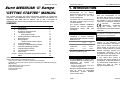
This manual provides the basic information required to install and
program a Euro-MERiDIAN G2/G3 system. Additional information for
upgrading with MSX Card to MSX-44, 134 or 256 is included in
supplementary instructions provided with the MSX Card (see below).
CONTENTS
Contents
1
2
3
4
5
6
7
8
9
10
11
12
13
14
Appendix
Introduction
Specifications
End Station Terminal Layout
Installation Guidance
Wiring Specifications
Installing End Station and Keypads
Wiring Detectors
Wiring Outputs
ATE and Communicator Outputs
The Keypad Display
Powering Up and Addressing Keypads
General Programming Principles
Programming the System
Test & Diagnostic Features
System Logs
Summary of Principal Programming Options
INDEX
Castle Care-Tech Ltd
Euro-MERiDIAN Getting
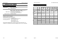
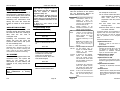
1. INTRODUCTION
The Euro-MERiDIAN is designed and
manufactured
to
our
ISO9001
approved quality system to offer a
choice of options to suit most
security applications.
All systems can be controlled using
PIN Codes, proximity tags or by key(or other) switches.
The system COM9600 DigiModem
provides for Remote Signalling,
Downloading
and/or
SMS
text
messaging.
Page
2
3
4
5
13
16
10
20
23
25
26
27
30
49
53
54
55
EN50131
Euro-MERiDIAN
is
suitable
for
installation in systems complying
with PD6662:2004 specified as follows
(BSIA Form 171):
Product
Security
Grade
Environment
Class
G2 Endstations
1 and 2
1 and 2
G3-MSX cards
1 to 3
1 and 2
G3 Plus
1 to 3
1 and 2
All power supplies conform
EN.50131-6 (BSIA Form 180)
Additional, and more detailed, information is available in the full "Engineering Manual"
Separate Technical Notes are available when using:
Access Control / Guard Tour Systems / External Set Unset Readers
DigiModem (including ARC digicom signalling, Downloading, and SMS text messaging)
iD Technology
Output Modules / STU Output Modules
Expansion with MSX Cards
Wards and Shunt Zones
Zone Expansion
Page 1
to
DD243:2004
The Euro-MERiDIAN ‘G’ range is fully
compliant with the requirements of
DD243:2004.
All
options
are
supported EXCEPT:
Zeroing of 'Confirm Timer' if first zone
to alarm retriggers (A.3.1).
Compliance Statement:
The Euro-MERiDIAN range complies
with the requirements of the
European EMC Directive (89/336/EC),
the Low Voltage Directive (72/23/EC
and 93/68/EC) & from (1/1/2006) the
“Reduction of Hazardous Substances
Directive
(2002/95/EC).
Appropriate
components
also
comply
with
the
requirements of the R&TTE Directive
(1995/5/EC).
It is essential that equipment and wiring
be installed to avoid being affected by
potential sources of interference.
WARRANTY
Castle Care-Tech Ltd will repair or
replace, at our discretion, any
product developing a fault within 2
years, free of charge. Products for
repair should be returned to the
factory, suitably packed to prevent
damage (including damage from
electrostatic discharges), and be
accompanied by full details of the
fault, and the full return address.
If the failure was caused by
operating the system outside of its
specification, by physical damage, or
by unauthorised modifications, we
reserve the right to raise an
appropriate repair charge.
We have a booklet available outlining
how to install to DD243:2004
specifications, request TN-DD243
from our sales office.
Page 2
Software
Started Manual
Castle Care-Tech Ltd
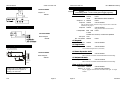
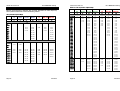
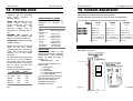
2. SPECIFICATIONS
Castle Care-Tech Ltd
Euro-MERiDIAN Getting
B: SYSTEM SPECIFICATIONS
A: ELECTRICAL SPECIFICATIONS
Mains Supply
Euro- G2 iD
230v AC Max 150mA
Fuse
Power Supplies
Battery Fuse
Supply out Fuses
Standby Battery
250mA slow blow
13·75v DC. Current rating as below.
Please ensure that power supply capacity is
adequate for the proposed system load.
1·5A quick blow (G2 endstation)
3·15A quick blow (G3plus Endstation)
800mA quick blow
17Ah
Ratings for all Power Supplies
Specified battery: 12v 17Ahr Lead-Acid
PSU Electrical Capability: G2 units: 1.5 A
G3 units & intelligent PSU: 2.5 A
Grade 1 Systems: 1.25 A
Grade 2 Systems: 1.0 A
Grade 3 systems: 700 mA
Note: When Intelligent PSU is used for Access Control purposes, it is
suitable for a maximum short-term loading of 2A for up to 15 seconds.
PSU Rating (EN50131-6):
5·00
G2 EoL
Page 3
Inputs (max)
ZEM Inputs
24
16
1x8
1x8
MSX44 iD
MSX44 EoL
G3+
iD
4x8
1 x 30
44
1x8
G3+
EoL
MSX134
iD
7x8
3 x 30
74
MSX134
EoL
MSX256
iD
14 x 8
7 x 30
134
MSX256
EoL
256
29 x 8
Set
points
(max) §
4
8
8
30
30
of which, max
keypads:
4
8
8
16
16
Other Devices
Max:
3
7
7
29
29
Level Sets
4
4
4
8
14
Full Areas
-
4
4
8
14
Wards (max)
-
7
7
29
29
Shunts
-
16
32
64
128
500
User/Managers
12
50
100
230
Duress/Guards
10
20
20
20
20
Logs
750
2000
2000
2000
2500
1
2
4
8
8
Output Mods
§ Includes keypads, tag readers, access control units and TMZs
Page 4
Software
Started Manual
Castle Care-Tech Ltd
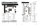
3. END STATION TERMINAL LAYOUT
Started Manual
Euro-G3 PLUS
H1
Slot for DigiModem
P20
B2
B3
TC
TD
TE
B1
B2
B3
B4
B5
F5 F6
C1
C2
C3
C4
C5
STU
Connector
If MSX-134 or 256 card is used
additional 24LC256 NVM is
required in the NVM2 slot.
F2
G1
F4
G2
G3
}
D1
D2
D3
D4
Earth
AC
Input
F3
B4
E1
E2
E3
E4
Terminal Allocations:
AC input:
1
Mains earth
2-3 Transformer
B
1
2
3
4
5
SAB:
O/p 2 –
O/p 1 –
Tamp Ret
HO –
HO +
1
2
3
Outputs:
Speaker –
+12v
O/p 3 –
C
D
1
2
3
4
E
1
2
RS.485
0v
+12v
‘A’
‘B’
iD bus (Euro-G2 iD only)
0v
+12v
Black
Red
(H11 is NOT used)
3
4
J
Line –
Line +
Not used
Blue
Yellow
H
only)
EoL Inputs (Euro-G2 EoL
1
2
3
6
7
8
11
12
13
4,9
5,10
Input 1
Common
Input 2
Input 3
Common
Input 4
Input 5
Common
Input 6
0v
+12v
Earth
AC
Input
{
5·00
F4
P1 P20
G1
G2
G3
H1
H2
H3
H4
H5
H6
H7
H8
H9
H10
H11
H12
H13
TA
TB
TC
TD
TE
J1
J2
J3
Fuse Allocations:
F1 (LED O4): +12v at terminals H
F2 (LED O1): +12v at terminals D
F3 (LED O5): +12v at terminals E
F4 (LED O6): +12v BATTERY
F5 (LED O3): +12v at terminals C
F6 (LED O2): +12v at terminals B
T Telecomms - see info
supplied with DigiModem
800mA
800mA
1.5 Amp
Engineer
Keypad
Connector
RESET
Tamper Switch
Jumper
P18
LED pulsing indicates communications normal
LED flashing at even on/off rate indicates fuse
overload
LED steady indicates fuse blown
F5: +12v at terminals C 800mA
F6: +12v at terminals B 800mA
Page 5
800mA
800mA
800mA
3.15Amp
800mA
800mA
Indications:
Fuse Allocations:
F1: +12v at terminals E or H
F2: +12v at terminals D
F4: +12v BATTERY
NVM
24LC256
B5
G
F1
NVM1
24LC256
F2
F5
F6
24LC256
JP1 (relay)
RESET
NVM2
Socket for
additional NVM
NVM (MSX-134 & 256)
A1
A2
A3
Line ‘A’ in
Line ‘B’ in
Line ‘A’ out
Line ‘B’ out
Telecom Ground
9
10
11
12
13
14
15
16
Euro-MERiDIAN
Slot for DigiModem
Slot for MSX Card/RS232 Card
C1
C2
C3
B1
TB
F1
E4/H13
D1
D2
D3
D4
TA
Slot for MSX Card
P1
H6
H7
H8
E1/H9
E2/H10
H11
E3/H12
STU/DigiCom
Outputs
1
2
3
4
5
6
7
8
Euro-G2 iD and EoL
H2
H3
H4
H5
Castle Care-Tech Ltd
5·00
Terminal Allocations:
A
Relay (see p.21)
1
C Contact
2
NC Contact
3
NO Contact
B
SAB:
1
O/p 2 –
2
O/p 1 –
3
Tamp Ret
4
HO –
5
HO +
C
Outputs:
1
Speaker 2
+12v
3
O/p 3 –
4
0v
5
O/p 4 +
D
RS.485
1
0v
2
+12v
3
‘A’
‘B’
4
E
iD bus
1
0v
black
2
+12v
red
3
Line –
blue
4
Line + yellow
G
AC Input
H
EoL Zones
1
Input 1
2
Common
3
Input 2
6
Input 3
7
Common
8
Input 4
11
Input 5
12
Common
13
Input 6
4,9
0v
5,10
+12v
T
Telecomms - see info
supplied with DigiModem
Page 6
Started Manual
Castle Care-Tech Ltd
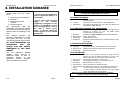
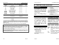
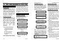
4. INSTALLATION GUIDANCE
An intruder alarm system can be
broken down into four major
parts:
1. Control Panel and Keypads
2. Detectors
3. Sounders and other
outputs
4. Communications
We
recommend
that
the
installation is carried out in these
four steps, and that each stage is
tested before proceeding to the
next.
Castle Care-Tech Ltd
Euro-MERiDIAN Getting
WIRING SPECIFICATION
NOTES:
1. Connections should NOT be
made to equipment whilst it is
powered up!
2. Please ensure that the power
supply
of
the
Control
equipment is adequate for the
system it is intended to power
from it. If appropriate, select a
unit with a larger power
supply, or include additional
power supplies in the system
specification.
This
manual
provides
the
necessary information to install
the system and carry out the
principal programming functions
For most installations, we
recommend
that
you
change only the options
highlighted in this basic
manual.
The following specifications must be observed when
installing Euro-MERiDIAN alarm systems:
A: General Principles:
1
Routing:
NO alarm system cable should be run with other cables carrying
AC or digital signals
2
Insulation:
Protect by the use of grommets, etc. where appropriate.
3
Specifications:
The following specifications for cable types and distances are
important for reliable operation.
B: RS-485 Wiring (Keypad, etc. connections):
1
Cores
4- core minimum. Use of 6-core and doubling up supply cores is
beneficial to minimise volt drop, but NEVER double
communications connections (D3-4).
2
Cable type:
Twisted pair, eg 9502 (screened) or Belden 9744 (unscreened)
3
Wiring format:
Parallel, ‘daisy-chained.’
4
Cable length:
Overall network max 1 Km.
5
Termination:
Extreme end points fitted with 470Ω resistors between D3 / D4 if
exceeds 20m.
C: End of Line Zone Wiring
The
full
Engineer’s
Manual
explains
these
options
in
additional detail, as well as
providing
details
of
the
additional
facilities
available
when the ‘MSX Card’ is fitted.
1
Cores
2
Cable type:
4- core
Standard alarm cable; screened if required by environment.
3
Wiring format:
Detectors wired using EoL resistors, mounted at detector.
4
Cable length:
Max 1 Km per detector.
D: iD PLUS Wiring
1
Cable type:
Screened. 4- core minimum. Doubling up supply cores will
minimise volt drop to detectors. Doubling of iD cores is also
possible. Spare cores should be earthed to prevent AC noise.
2
Wiring format:
Any parallel format, except ‘ring main’ loops.
3
Termination
0.01µF capacitor between iD+/- at end of each cable run.
4
Cable length:
Max 100 metres for any cable run.
5
Biscuit location:
Must be wired directly to detector terminals.
6
Checks:
All commissioning checks must be performed and recorded.
7
Warning:
In some situations, especially take-over sites using existing
wiring, iD technology may not be suitable.
If it is impossible to locate the biscuit in this way, a ‘DP’ junction box must be used.
Castle Care-Tech Ltd cannot be held responsible for problems
arising from failure to follow this specification
5·00
Page 7
Page 8
Software
Started Manual
Castle Care-Tech Ltd.
5. INSTALLING END STATION and KEYPADS
THE END STATION
Mount
the
End
Station
securely using 4 fixing screws.
MAINS
ELECTRICITY IS
DANGEROUS
The mains connection to the
End Station should comply
with BS.7671, and be made by
a competent electrician from
the
consumer
unit
or
unswitched fused spur.
NE L
The
mains
cable
should
be
routed
through
the
inlet
adjacent
to
the
connector block. Do
NOT use an alternative
inlet, or loop the
mains wire within the
housing, to avoid the
EMC
performance
being degraded.
Fuse
250mA
Started Manual
WIRING Keypads and Tag
Readers
These require a minimum 4-core
connection. 6-cores is preferred,
with the supply connections
(D1,2) doubled up to minimise
voltage drop. Twisted pair cable
should be used.
Do
NOT
double
up
the
communications
pair
(D3,4)
under
any
circumstances.
Simply connect terminal D1 to
D1, D2 to D2, etc.
Castle Care-Tech Ltd
Devices should be wired in
sequence (‘daisy-chained’) rather
than starred or spurred.
In the event of a keypad or tag
reader being located more than
100 metres from the End Station,
or if the supply voltage at the
device falls to 11 volts or less, we
recommend that it be powered
from a local power supply.
The supplied 470-ohm resistors
should
be
fitted
between
terminals D3 and D4 at the device
at each end of the RS-485
network, as below:
CAUTION:
Disconnect the mains supply before removing the cover.
Never add equipment to the system with power applied.
KEYPADS and TAG READERS:
Similarly, mount the Keypads and
Tag
Readers
as
required.
NOTE: Keypads and Tag Readers
should NOT be mounted on a
metal surface, or within 0·6
metres of each other, to prevent
degradation of tag response.
Tag Readers, Access Control
Points and TMZs must be
addressed before being powered
up. These must be allocated in the
same number series.
Address 00 is always reserved for
the principal Keypad.
Keypads are addressed in software
(see page 21) in the SAME number
sequence (0-x) as Tag Readers, etc.
Zone Expander Modules and Output
Modules are addressed in the same
3.00
way, but in independent number
sequences (0-x).
Address Switch 1
Switch 2
Switch 4
0
Closed
Closed
Closed
1
OPEN
Closed
Closed
2
Closed
OPEN
Closed
3
OPEN
OPEN
Closed
4
Closed
Closed
OPEN
5
OPEN
Closed
OPEN
6
Closed
OPEN
OPEN
7
OPEN
OPEN
OPEN
470 Ω resistor — connect to last
item at each end of network
Switch 8 should be CLOSED.
The address switches on TMZs
and
ZEMs
work
slightly
differently. Switches should be
pulled towards the numbers
printed on the PCB to add up to
the address required. Example
below shows address 01.
Page 9
Remember to put the 470Ω resistors at each
end of the RS485 data BUS. (If the overall cable
length is less than 20m the resistors should not
be used).
Colour code 470Ω : Brown / Red / Brown
5·00
Page 10
Started Manual
Castle Care-Tech Ltd
6. WIRING DETECTORS
2K2
alarm
4K7
The 2K2 resistor MUST be
located at the furthest point on
the wiring circuit, or the wiring
security it provides will be lost.
To panel zone terminals
Endstation Input Wiring:
1: Wire between H1 & H2
2: Wire between H3 & H2
3: Wire between H6 & H7
4: Wire between H8 & H7
5: Wire between H11 & H12
5·00
6: Wire between H13 & H12
blue
fault
Figure 1
12K
2K2
+ -
Tamper
Alarm
Grade 3 Systems
If “MASKING” terminals not present on detector, link ‘biscuit 2’ yellow
wire direct to line.
Mask
4K7
If “FAULT” terminals not present, link ‘biscuit 2’ blue direct to line
and short ‘biscuit 2’ white to blue.
To panel zone terminals
+ -
tamper
Biscuit 1
6K8
2K2
Please select the correct wiring
configuration from those shown
on this page which match the
terminals in your detector.
Keypad/TMZ Input wiring:
1: Wire between K1 & K3
2: Wire between K1 & K4
alarm
To panel zone terminals
Resistor colour code:
A link must be fitted between
the alarm and fault terminals as
shown right. The 2K2 resistor
MUST be located at the furthest
point on the wiring circuit, or
the wiring security it provides
will be lost.
tamper
yellow
+ -
Grade 3 Systems
2K2 – Red / Red / Red / Gold
4K7 – Yellow / Purple / Red / Gold
6K8 – Blue / Grey / Red / Gold
12K – Brown / Red / Red / Gold
Blue wire (iD negative)
should connect to
endstation terminal E3.
Yellow wire (iD positive)
should connect to
endstation terminal E4.
fault
blue
tamper
white
+ -
Grade 2 systems
yellow
Grade 2 sytems
2K2 – Red / Red / Red / Gold
4K7 – Yellow / Purple / Red / Gold
Euro-MERiDIAN Getting
iD PLUS WIRING
End of Line Wiring
Resistor colour code:
Castle Care-Tech Ltd
alarm
y
fault
4K7
+ -
+ -
Tamper
Alarm
w
Alarm
w
Fault
blue
To panel zone terminals
2K2
Tamper
bl
6K8
12K
Fault
Mask
Biscuit 1
Biscuit 2
To panel zone terminals
bl
y
y
Mask
yellow
Tamper
bl
Biscuit 2
w
w
bl
Alarm
y
Mask
blue
yellow
To panel zone terminals
NORMALLY OPEN DETECTORS should be connected in the same way, with
the ‘Normally Open’ attribute selected when programming the zone.
4K7
To panel zone terminals
Page 11
Page 12
Software
Started Manual
Mount all detectors in the
required locations, and wire
them to the iD bus in any parallel
configuration – parallel, spur or
star – as above.
NORMALLY OPEN DETECTORS
should be connected in the same
way, with the ‘Normally Open’
attribute
selected
when
programming the input.
For input number identification,
refer page 27,28.
iD LINE TERMINATION
Each cable run should be
terminated
with
a
0.01µF
capacitor connected between iD
+ and - (yellow and blue) at the
last biscuit
Reminders for successful
installation of an iD system:
1.
Ensure that all biscuits are
correctly connected
2.
Do not mix iD and iD Plus
biscuits
3.
Ensure
that
safe
wiring
distances are not exceeded and
cable
runs
are
correctly
terminated (0.01µF capacitor).
Castle Care-Tech Ltd
If you are not familiar with iD
wiring, please request Technical
Note “Installing iD Systems” for
additional information.
Note on Programming Biscuits
for Grade 3 systems:
Paired Input?
Yes
[1]
When programming both
biscuit 1 and 2 (see page 12),
set this to yes.
Fault Input?
No
[0]
Castle Care-Tech Ltd
7. WIRING OUTPUTS
When wiring outputs, do not exceed the maximum rating
for individual outputs, or the system power supply.
SAB Connections
OUTPUT RATING
Strobe and Siren Outputs are
rated for 800mA each. Note
that the 'Hold Off' fuse is rated
as 800mA.
Ensure that the system
power
supply
is
not
overloaded.
Current Available:
If programming biscuit 2,
the biscuit connected to the
mask/fault terminals of the
detector, set this to ‘yes’,
otherwise leave at ‘no’.
O/p
1
(siren):
800mA
O/p
2
(strobe):
800mA
Hold
Off:
800mA
Note tamper return
is NEGATIVE.
Paired With?
Enter the input number of
the biscuit you are pairing
with (for each input of the
pair), e.g. if programming
biscuit 2, enter the input
number of biscuit 1.
Euro-MERiDIAN Getting
Other End Station Outputs
Current Available:
Speaker:
500mA
4.
Ensure that all biscuits are
wired directly to the detector
Output 3:
5.
Ensure
that
cabling
specifications are carefully
followed (see page 8).
Output 4:
6.
5·00
100mA
100mA
NOTE: Output 3 may also be
used at relay terminals ‘A’ on
Euro-G3+. Select jumper JP1
at left, linking pins 1 and 2
Ensure that the resistance
measurements are correctly
checked and recorded.
Page 13
Page 14
Software
Started Manual
Castle Care-Tech Ltd
Keypad Outputs
Castle Care-Tech Ltd
Euro-MERiDIAN Getting
OUTPUT
CAPABILITIES
Current
Available
:
Current Available:
Please
note the capabilities of each output, and avoid
100mA
overloading them – or the overall power supply capacity.
Output 1:
Output 1:
100mA
At End Station:
Hold Off
650mA
(cont)
Fused
Max 800mA in alarm condition
Outputs 1 – 2
Output 3
800mA
100mA
Fused
Current limited
Volt free Relay contacts, rated at 3 Amps, may be used on Euro-G3+
endstations, see page 14
Set/Unset Tag Reader Outputs
Output 4
100mA
Current limited
Only present on Euro-G3+ and above
Loudspeaker
Current Available:
‘ATE’ pins
Aux. 12v outlets
Each Output:
100mA
At Keypad:
Output 1
800mA
Fused
100mA
Current limited.
100mA
Current limited
At Tag Reader:
TMZ Outputs
Outputs 1 – 2
O/P 3 on TMZ is loudspeaker drive (16 ohm load)
1 or 2 16ohm Speakers
may be wired in parallel
-Ve
+12v
o/p
2
Max load Fused
8 ohms
Suitable for 1x8 ohm, or 2x16 ohm speakers
1mA
o/p
1
-Ve
-Ve
C1
L1
L2
L3
At Zone Expander Unit:
Current Available:
Outputs 1 – 4
250mA
Current limited
Note: restricted to maximum of 400mA simultaneous total loading.
Each Output:
500mA
At Output Module:
Outputs 1 – 16
End Station
Terminals
250mA
Current Limited
Note: restricted to maximum of 400mA simultaneous total loading.
Plug-on Relay Interface
O/Ps R and S
Relays 1 – 6
NOTE: Output 3 on TMZ units is a
loudspeaker driver capable of
driving a 16 ohm load.
5·00
800mA
2.5 A
Current limited
Volt free relay contacts
May be plugged onto Euro-G3+ End Station ‘STU pins’ or Output
module.
Page 15
Page 16
Software
Started Manual
Castle Care-Tech Ltd
COMMUNICATIONS OUTPUTS
Remote
communication
possible by:
is
(i) The Snsp-In DigiModem
The pin and loom colour
allocation for these outputs is as
follows:
Pin
1
Loom
colour
BROWN
2
Program
o/p No.
Default
$
'Line
input
RED
$
'RedCare
Reset' OR
'Fail to
Communicate
' input
3
ORANGE
-
+12v supply
For full details, refer to Technical
Note “Installation and use of
COM9600 DigiModem.”
4
YELLOW
5
Tamper
(ii) A Hard-wired STU (or
Dual Path Signalling
Device)
This may be used to provide
‘digicom’ signalling to an ‘Alarm
Receiving Centre,’ Downloading
to a PC running Euro-InSite
software
and/or
SMS
text
messages to a mobile ‘phone.
A 14-pin connector is available on
G2 endstations, which can be
used with a plug-on loom (cat
no. EUR-114) to connect to a STU
or communicator.
To activate the ATE pins, an
MSX-44, -134 or -256 card must
be fitted.
NOTE:
This loom must be plugged on with
the BLACK wire towards the BOTTOM
of the printed Circuit Board.
Please ensure that the ATE is
correctly programmed.
Fault'
5
GREEN
1
Fire
6
BLUE
6
Confirmed
Any
7
MAUVE
3
Unconfirmed
Any
8
GREY
2
HU
Any
Device
9
WHITE
-
0v supply
10
BLACK
4
Set Any
11
WHITE
7
Omit Rearm
12
BLACK
9
Fault
13
MAUVE
10
Test ATS
14
GREY
8
Mains Fail
Outputs provide +5v dropping to 0v
when
triggered
and
have
insufficient drive current available
for any other application.
An option “Output Invert” is
available to invert these outputs for
‘positive applied’ signalling. See
page 44
Page 17
Euro-MERiDIAN Getting
(iii) A Plug-on STU (or
Dual Path Signalling
Device)
Any communicating device with
the industry standard footprint
may be plugged onto the G3-plus
End Station ‘ATE’ pins. The pin
allocation for this device is
shown below.
Inputs are configured to accept
+v triggers (5v). These inputs
must be enabled as shown on
page 44 (ATE-Reply).
Please ensure that the ATE is
correctly programmed.
NOTES:
The channels triggered on a STU
(except Versus GSM STU) are NOT
identical to those on a Digicom.
Programming a Digi/Dualcom or Versus GSM STU
Digi
Channel
1
2
3
4
5
6
7
10
Default Output Type
Fire (0001)
Zone PA Any (0009)
Unconfirmed (0018)
Set All † (0004)
Tamper Any (0007)
Confirm Any (0006)
Zone Omit at Rearm (0017)
ATE Not Used (0066) *
ATE Not Used (0066) *
Test ATS (0064)
Panel Programmable PCB Pin
Output No.
No.
ATE OP 1
1
ATE OP 2
2
ATE OP 3
3
ATE OP 4
4
ATE OP 5
5
ATE OP 6
13
ATE OP 7
14
ATE OP 8 §
16
ATE OP 9
8
ATE OP 10
11
Inputs
Channel set-up for Hard-wired ATE
$ - These input configurations must
be enabled in 'Site Options' - see
page 44. Inputs are configured to
accept +v triggers (5-12v).
5·00
Castle Care-Tech Ltd
RedCare Reset (STU only)
See page 48
Fail to Communicate
See page 48
7
Line Fault
See page 48
15
6
Supply
+12v supply
-
9
0v supply
-
10
+5v supply
-
12
NOTES:
Outputs provide positive removed signalling (ie +5v switching to 0 volts when
active) An “output invert” option for ‘+ve applied’ signalling is available.
Insufficient current is available for other uses. See page 44.
* - If positive applied signalling us used, these outputs must be changed to type
0000 (unused), except if required by §
† - If you are using the panel in level setting mode, this must be changed to Set ANY
(type 0022). Alternatively, it should be changed to “Misoperation” (0005) if set /
unset monitoring is not required.
§ - If 18
ATE requires digi reset output, programme ATE OP 8 as Reset Digi 0060.
Page
Software
Started Manual
Castle Care-Tech Ltd
Castle Care-Tech Ltd
Euro-MERiDIAN Getting
Programming a STU (Excluding VERSUS GSM STU)
STU
Channel
1
2
3
4
5 or 7
6
Not Used
Not Used
Not Used
Not Used
Default Output Type
Test ATS (0064)
Panel Programmable
Output No.
ATE OP 1
ATE OP 2
ATE OP 3
ATE OP 4
ATE OP 5
ATE OP 7
ATE OP 8
ATE OP 9
ATE OP 6
ATE OP 10
RedCare Reset Input
See page 48
6
Line Fault Input
See page 48
15
Fire (0001)
Zone PA Any (0009)
Unconfirmed (0018)
Set All † (0004)
Tamper (0007)
Zone Omit at Rearm (0017)
ATE Not Used (0066)*
ATE Not Used (0066)*
Confirm Any (0006)
PCB Pin
No.
1
2
3
4
5
14
16
8
13
11
Inputs
Supply
+12v supply
9
0v supply
10
+5v supply
12
As outputs 8 and 9 are not connected on ATE, additional inputs are
available on ATE terminals which may be wired from Endstation
outputs 3 and 4.
Note: output will require a 1k resistor to 12v for correct operation.
NOTES:
Outputs provide positive removed signalling (ie +5v switching to 0 volts when
active) An “output invert” option for ‘+ve applied’ signalling is available.
Insufficient current is available for other uses. See page 44.
* - If positive applied signalling us used, these outputs must be changed to type
0000 (unused), except if required by §
† - If you are using the panel in level setting mode, this must be changed to Set ANY
(type 0022). Alternatively, it should be changed to “Misoperation” (0005) if set /
unset monitoring is not required.
8. THE KEYPAD DISPLAY
Note: A ‘force backlight’ option is
available via each individual keypad
menu.
1 = End Station
2 = Keypad
3 = Tag Reader
4 = Zone Expansion Module
5 = Output Module
The remaining digit(s) identify
the individual device of the type,
eg: Mains Failure 401 =
ZEM addressed as 01
485 Fail 203 =
Keypad addressed as 03
Area LEDs
Display Options
The ABCD keys at Keypads
contain LEDs, which illuminate at
all relevant times to indicate the
security patterns being set/unset
or
programmed.
This
is
functional
for
appropriate
security
patterns
on
LEVEL
setting systems, and for first
four (principal) areas on area
setting systems.
(i) Customise Text Strings
Backlighting
LCDs and Keypad keys are backlit.
The backlighting will illuminate
at the start of entry and exit
times, and at key entry, and will
remain lit for 30 seconds after
the last key entry, or termination
of the function.
Fault Indications
Fault indications shown on the
Liquid Crystal Display will include
a numeric identification of the
individual device at which the
fault is present, eg
Mains Failure 401
485 Fail 203 etc.
The first digit identifies the
device type:
5·00
Page 19
Page 20
The ‘Area setting’ text strings
can be programmed to make the
display meaningful to the user.
Additionally,
the
‘Sign-on
message’ can be customised.
(ii) Display characteristics
The system can be tailored to
display
certain
information
without requiring a code entry:
Display
when
set
Enables the system to
display the status of the
areas whilst set, AND alarm
events
Not compliant with PD6662:2004
Site
Name
Identification name for
site (used for SMS messages
and up/downloading).
Software
Started Manual
Castle Care-Tech Ltd
9. POWERING UP and ADDRESSING
the KEYPADS
Pre Power-Up Checks
Prior to powering up the system,
a final check should be made of:
1.
POWER SUPPLIES – adequate
for the load to be applied.
2.
WIRING
–
conforms
to
specifications in this manual.
3.
CONNECTIONS
–
correctly
made,
with
no
loose
‘whiskers,’ etc.
When you are satisfied that all is
correct:
Powering Up
Power up the End Station on
MAINS ONLY.
Go to the first keypad, which will
be showing
ADDRESS
[- -]
Key 00 and A
Euro-MERiDIAN
Time:
00:03
The system will be generating a
tamper alarm, use default code
(1234) to silence. When
‘Battery Fault’ is indicated (NOT
BEFORE), the back-up battery
should be connected.
If you have more than one
keypad on the system, they must
all be addressed in the same way,
ensuring
that
no
address
duplicates another Keypad, Tag
Reader or Access Control Point.
When this has been done, any
additional power supplies may
be powered up – noting the
same need to await a ‘Battery
Fault’
indication
before
connecting the back-up battery.
NOTES:
A blank keypad display may mean
that it has previously been coded to
an address other than 00 (eg for test
purposes). Press the D key for 10
seconds to access the menu to
enter the correct address as above.
When prompted to enter a code,
this is ‘2000.’
Additional keypads, and any tag
readers on the system will NOT
work unless they are correctly
addressed, AND enabled in the
engineer menu, as shown on page
37.
Castle Care-Tech Ltd
Euro-MERiDIAN Getting
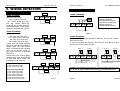
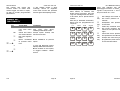
10. GENERAL PROGRAMMING PRINCIPLES
The
various
functions
are
selected and manipulated as
follows. For simplicity, where
menu content and data entry are
straightforward and obvious, no
detail will be provided in this
basic manual.
INHIBIT FIRE/HU?
ENTERING ENGINEER MENU
The system is now in the
Engineer ‘Main’ menu. This gives
access to a number of ‘sub’
menus, each of which enables a
system function, or group of
associated functions, to be
programmed.
On a new system, only Keypad
00 is enabled by default, and it
‘Main’
menu
items
are
distinguished by using CAPITALS.
is therefore necessary to use this
keypad until the remainder are
enabled from the Engineer
Programming Menu.
NOTE: The system MUST be fully
unset before the Engineer or
Manager menus can be accessed.
EXIT FROM ENGINEER MENU
On completion of programming
or
use
of
test/diagnostic
functions, the system can be
returned to normal mode by:
EXIT ENGINEER
MENU?
Euro-MERiDIAN
Time:
17:24
Press YES or A
Enter engineer code
(default 1111)
Please Wait
Saving NVM data
SET/UNSET SYSTEM?
Please Wait
Checking System
Press NO
Euro-MERiDIAN
Time:
17:24
FORCE ARM ON 1st
ZONE?
OR:
Press NO
With the display showing any
MAIN menu item (ie shown in
CAPITALS), press A. The sequence
followed will then be as above.
A tamper alarm is
generated
Enter Code
[
]
Enter engineer code again
Alarm silences
5·00
Page 21
Page 22
Software
Started Manual
Castle Care-Tech Ltd
The system will check the
current status of zones that
would trigger an alarm if open,
as well as certain programmed
parameters.
If the display shows a fault
message, return to engineer
menu and correct the problem
before again attempting to exit.
GENERAL KEY
FUNCTIONALITY
Key
NO
YES
A
B
B=Í
D=Î
5·00
Euro-MERiDIAN Getting
TEXT PROGRAMMING
Text may be programmed for
Zone names, to identify the
area(s) being set/unset, and the
‘Sign-on’ message and site name.
In all cases, this is performed as
follows:
Each key is allocated characters,
which may be programmed as
required:
In main menu
In sub menu
Moves forwards to
next main menu
item
Selects and enters
sub menu indicated
Exit from Engineer
menu
Moves backwards
to previous menu
item
Answers questions, also exits to
next
menu
level
above,
retaining all alterations made
Accepts option offered, and
moves to next item
-
C
D
Castle Care-Tech Ltd
-
Page 23
abc2
def3
1
2
3
ghi4
jkl5
mno6
4
pqrs7
7
Moves backwards to previous
option
In Logs and Diagnostic menus,
displays additional information
Moves forward to next option,
or toggles between ‘YES/NO’
choices.
,/+.1
5
tuv8
8
0
A
6
B
wxyz9
clear
9
_0
NO
capital
YES
C
D
Press the relevant key the
appropriate number of times –
eg the 5 key once for ‘J’ the 7
key four times for ‘S’ etc.
A
key
will change the letter at
the cursor position to a
CAPITAL.
B
key
backspaces one position
to the LEFT.
C
key
clears any character from
the cursor position, and
moves it one space to the
right.
D
key
moves the cursor position
one position to the RIGHT.
YES
key
accepts the text string as
programmed, and returns
to the relevant menu.
s
Page 24
Software
Started Manual
Castle Care-Tech Ltd
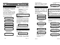
11. PROGRAMMING THE SYSTEM
CLEAN START
It is essential that a ‘clean start’
be performed at initial power up
of a new system, to ensure that
the initialisation is correct to
true factory defaults.
If the Non-Volatile Memory (NVM)
chip is ever removed from the
End Station, it MUST be replaced
before starting programming.
To perform a ‘clean start’:
With the display showing
CLEAN START?
Press YES
Clean Start?
[
]
Enter 2000
Clean Start?
Please Wait
Panel has been
clean started!
Press YES
Clear Codes?
If you wish to keep the
existing codes on the
system press NO,
otherwise press ‘Yes’
Initialise Logs?
Press ‘Yes’ to clear logs
4·00
The system memory will now be
restored to factory defaults,
EXCEPT:
Keypad 00 remains enabled
at all times
Keypad in use remains
enabled.
Current Keypad areas are
NOT changed
Note: If a new NVM chip is to be
used, Logs must be cleared (see
page 49)
INHIBIT FIRE/HU?
It is possible to prevent the panel
from alarming from fire or Hold
Up zones whilst in engineering
menu through this option. Please
be aware of the potential liability
and hazard of inhibiting these
zone types.
INHIBIT FIRE/HU?
When
you
come
out
of
engineering, the inhibited zones
will be re-instated automatically.
Castle Care-Tech Ltd
Euro-MERiDIAN Getting
number and product, and should
always
be
checked
before
contacting Technical Support.
MODE SELECTION
The G3+ panel defaults to accept
‘End of Line’ wiring, but may be
programmed
to
use
‘iD’
technology by changing the
setting in the ‘Mode’ menu. The
G2-EoL endstation is EoL only and
G2-iD is iD only.
With display showing
CHANGE MODE?
Press YES
Detection Mode
EoL
[ 1]
Use D to select between
iD [0] and EOL [1]
(on Euro G3+ & above only)
Press YES
EOL Mode
DR
[ 1]
Do not adjust this setting
unless single-resistor
wiring is to be used.
Press YES
Zone Response
400 mS
[08]
SOFTWARE REVISION
Selecting this option will display
the software version fitted to
the system, eg
Rev 5.00 UK
12345678 G3+74
This identifies the software
version number, software serial
Page
Press YES
CHOOSE MODE?
Press NO
Moves to next menu item
NOTES:
On systems with Zone Expander
Modules fitted, the zones will be
arranged as shown in the table on
page 27,28.
Zones wired from Keypads / Tag
Readers will ALWAYS be ‘End of
Line,’ regardless of mode selected.
ENABLE ZEMS
Before a ZEM can be used, it
must be correctly addressed (see
page 9) AND enabled in software
as follows:
With display showing
ENABLE ZEMs?
Press YES
ZEM Address
[ 0]
Select ZEM to be enabled,
eg press 1 and YES
Do not adjust this setting
Press YES
ZEM Installed
No
[0]
Zone XDF
Off
[0]
DO NOT CHANGE THIS
SETTING, unless specifically
advised to do so by Castle
Care-Tech Ltd Technical
Support staff.
Use D to select ‘Yes [1]’
and press YES
ZEM Address
[ 1]
Repeat for additional
ZEMs or Press NO
25
Page 26
Software
Castle Care-Tech Ltd
Euro-MERiDIAN Getting
Castle Care-Tech Ltd
Euro-MERiDIAN Getting
INPUT PROGRAMMING
End of Line Systems Input Map
Before programming, identify the number allocated to each input by
the system software from the following tables.
Euro-
iD Systems Input Map
EuroZones
G2
iD
24
MSX-G3iD-44
44
MSX-G3iD-256
256
G3 PLUS
74
74
G3 PLUS
MSX-134
134
G3 PLUS
MSX-256
256
End
Station
1 -10
1-30
1 –30
1-30
1-30
1-30
1-30
ZEM 0
ZEM 1
ZEM 2
ZEM 3
ZEM 4
ZEM 5
ZEM 6
-
-
31-60
61-90
91-120
-
31-60
61-90
91-120
121-150
151-180
181-210
211-240
31-60
-
31-60
61-90
91-120
-
31-60
61-90
91-120
121-150
151-180
181-210
211-240
End Station
-
-
-
-
61-66
121-126
241-246
ZEM 0
ZEM 1
11-18
31-38
-
-
-
-
-
K’PAD 00
K’PAD 01
K’PAD 02
K’PAD 03
K’PAD 04
K’PAD 05
K’PAD 06
K’PAD 07
19-20
21-22
23-24
-
127-128
129-130
131-132
133-134
-
247-248
249-250
251-252
253-254
255-256
-
EoL Inputs
Page 27
MSX-G3EoL-44
44
MSX-G3EoL-134
134
1-6
7-14
15-16
-
1-6
7-14
15-22
23-30
31-38
39-40
41-42
43-44
-
1-6
7-14
15-22
23-30
31-38
39-46
47-54
55-62
63-70
71-78
79-86
87-94
95-102
103-110
111-118
119-120
121-122
123-124
125-126
127-128
129-130
131-132
133-134
-
MSX-G3EoL-256
256
G3 PLUS
74
74
G3 PLUS
MSX-134
134
G3 PLUS
MSX-256
256
1-6
7-14
15-22
23-30
31-38
39-46
47-54
55-62
63-70
71-78
79-86
87-94
95-102
103-110
111-118
119-120
121-122
123-124
125-126
127-128
129-130
131-132
133-134
-
1-6
7-14
15-22
23-30
31-38
39-46
47-54
55-62
63-70
71-78
79-86
87-94
95-102
103-110
111-118
119-126
127-134
135-142
143-150
151-158
159-166
167-174
175-182
183-190
191-198
199-206
207-214
215-222
223-230
231-238
239-240
241-242
243-244
245-246
247-248
249-250
251-252
253-254
255-256
EoL Inputs
MSX-G3iD-134
134
iD Inputs
39-40
41-42
43-44
-
Zones
G2
EoL
16
121-122
123-124
125-126
127-128
129-130
131-132
133-134
-
241-242
243-244
245-246
247-248
249-250
251-252
253-254
255-256
67-68
69-70
71-72
73-74
-
Software
End Station
ZEM 0
ZEM 1
ZEM 2
ZEM 3
ZEM 4
ZEM 5
ZEM 6
ZEM 7
ZEM 8
ZEM 9
ZEM 10
ZEM 11
ZEM 12
ZEM 13
ZEM 14
ZEM 15
ZEM 16
ZEM 17
ZEM 18
ZEM 19
ZEM 20
ZEM 21
ZEM 22
ZEM 23
ZEM 24
ZEM 25
ZEM 26
ZEM 27
ZEM 28
K’PAD 00
K’PAD 01
K’PAD 02
K’PAD 03
K’PAD 04
K’PAD 05
K’PAD 06
K’PAD 07
Page 28
1-6
7-14
15-22
23-30
31-38
39-46
47-54
55-62
63-70
71-78
79-86
87-94
95-102
103-110
111-118
119-126
127-134
135-142
143-150
151-158
159-166
167-174
175-182
183-190
191-198
199-206
207-214
215-222
223-230
231-238
239-240
241-242
243-244
245-246
247-248
249-250
251-252
253-254
255-256
6
7-14
15-22
23-30
31-38
39-46
47-54
55-62
63-64
65-66
67-68
69-70
71-72
73-74
-
Software
Started Manual
INPUT TYPES
00
01
02
03
04
05
06
07
08
Type
Unsed
Operation
Factory default
Zone is out of operation
Fire
Active at all times
Audible response: Full
(differentiated)
Communicator: ‘Fire’ signal
Gas
Active at all times
Audible response: Full
(differentiated)
Communicator: ‘Gas’ signal
PA
Active at all times
Audible response: Full
(differentiated)
Communicator: ‘Hold Up’
and ‘HU Input’ signals
Silent
Active at all times
PA
Audible response: None
Communicator: ‘Hold Up’
and ‘Zone PA’ signals
Tamper When unset:
Audible response: Internal
Communicator: ‘Tamper’
signal
When set:
Audible response: Full
Communicator: ‘Tamper’ +
‘Intruder’ signals.
Intruder Active when set
Audible response: Full
Communicator: ‘Intruder’
signal
Final
Active when set – initiates
Exit
Entry time
If system not unset before
(FX)
entry time expires:
Audible response: Full
Communicator: ‘Intruder’
signal
Entry
Active when set, except
Route
during entry time
Audible response: Full
(ER)
Communicator: ‘Intruder’
signal
Page 29
Castle Care-Tech Ltd
09
Type
ER
/Area
FX
10
FX
/Area
ER
Operation
When Fully set, acts as ER
zone, as above
When ‘Part’ set, acts as FX
zone, as above
When Fully set, acts as FX
zone, as above
When ‘Part’ set, acts as ER
zone, as above
Active during exit time to
complete setting procedure.
No audible or
communicator response.
11
PTS
12
Switcher Active at all times.
No audible or
communicator response.
Triggers associated output
for switching other
equipment.
13
Day Alarm
15
Ward Control
Additional types
available for
advanced
applications – see full
Engineering Manual
16
Fault
17
Closure
Supervision
18
Shunt
19
Unset
Active when set. Accepts
input from Keyswitch (or
equivalent) to UNSET the
area(s) assigned to it
20
Keyswitch
Accepts input from
Keyswitch (or equivalent) to
set / unset the area(s)
assigned to it. Setting
includes normal exit time,
etc.
(Latch)
21
Entry
Shock
22
Keyswitch
Active when system set.
Works in conjunction with
"FX" zone type for
detection of forced entry.
See next page for details.
As type 20, but accepts a
pulsed input such as a radio
(Pulsed) pendant to set/unset
system
Software
Castle Care-Tech Ltd
NOTES:
‘Part’ set refers to levels B, C or D on a
‘Level Setting’ system, or to any
combination other than all available areas
on an ‘Area Setting’ system.
By default, all inputs are pre-set as ‘unused’
and must be programmed before the
system can be used. The input will NOT be
live, and therefore cannot be Walk tested,
until after exiting Engineer mode.
A trigger from an ‘Entry Route’ input will be
stored for 2 seconds before an alarm is
activated. If a Final Exit input is triggered
within this time, the system will select entry
time, rather than an immediate alarm.
Entry Shock Input Type*
This input type is always used in
conjunction with a 'Final Exit' input.
The 'FX' input is a door contact on the
initial entry door, the 'Entry Shock'
input is a non-latching shock sensor
fitted to the door frame in the vicinity
of the lock.
If the initial entry door is subject to
gross attack and forced open, an
alarm will be triggered and at the
expiry of entry time only one further
intruder detector needs to be tripped
to signal a sequentially confirmed
alarm - the 'Entry Shock' input counts
as the first to alarm.
The Final Exit door contact must be
opened within 10 seconds of the
shock detector triggering for the
Entry Shock response to apply.
Triggering the Entry Shock input in
isolation will NOT generate an alarm of
any kind.
* Entry Shock input type is only used if
the system is installed to comply with
DD243:2004 using unsetting in accord
with section 6·4·5.
Software
Euro-MERiDIAN Getting
SECURITY PATTERNS
G2 panels use LEVEL setting, G3+ and MSX
panels may use LEVEL or AREA setting.
LEVEL SETTING
The user has a choice of setting A or B
or C or D. Each ‘set’ level will provide a
different pattern of security coverage.
Each input therefore will need to be
allocated to the required levels.
For example, the front door may need
to be active in all setting scenarios, and
would therefore be programmed as
[ABCD]. On the other hand, the master
bedroom may only need to be active if
ALL the system is set, and would
therefore be assigned to [A
]. The
kitchen may need to be active at all
times, except when the dog is left at
home (‘D’ set) and at night (‘B’ set) and
would be programmed [A C ].
AREA SETTING
The user has the option of setting any
combination of the areas, and of
‘adding to’ or ‘subtracting from’ the list
of areas set.
NOTE: When partially set, the default will be
to ADD additional areas up to the validity of
the code, unless entry time has started, in
which case relevant areas will be Unset.
Normally inputs will be allocated to a
single area. Alternatively, they may be
programmed to more than one area, in
which case the choice is available of
‘ANY’ (inputs live if any of programmed
areas is set) or ‘ALL’ (inputs live only if
all of programmed areas are set).
Page 30
Started Manual
Castle Care-Tech Ltd
ZONE ATTRIBUTES
Attribute
Response modification
System
loudspeaker(s)
will
Chime
‘chime’ when detector triggered
whilst relevant area is unset.
Note: zone concerned will NOT
indicate on display.
Single System chimes once when
detector triggered
Follow System chimes until detector is
cleared.
Applicable to ‘Intruder’ ‘FX’ ‘EN’ and
‘Switcher’ zones.
Omittable Enables input to be manually
omitted during the setting
procedure
Normally Enables the system to respond
correctly when detectors of
Open
‘normally open’ configuration
are wired to the system.
Alternatively converts input
types which default to ‘normally
open’ (eg PTS) to operate with
normally closed devices.
The control will only generate an
Double
alarm if this input is triggered
knock
twice within a pre-set period, or
if the input remains open for
that period.
Dual Trip The Control will only generate an
alarm if this input, and another
like-programmed input with
adjacent number, are in active
condition at the same time.
Either
detector
in
fault
condition will prevent the
system from setting. Both
detectors must be wired
using the same technology (iD
or EoL) from the same device.
Forces a log entry when the
Special
input is opened or closed, even
Logged
when an alarm does not result.
May be selected to apply when
system is set, when unset, or
always.
5·00
Castle Care-Tech Ltd
PROGRAMMING STEPS
Attribute
Paired
Input
Fault
Input
Paired
With
Confirm
Group
Response modification
This attribute MUST be selected
for switcher inputs required to
activate SMS text messages.
For use in Grade 3 iD systems.
Select to ‘YES’ for each of the
two biscuits acting as the input.
(see page 12 & 13)
For use in Grade 3 iD systems.
Select to ‘YES’ for the biscuit
acting as the ‘anti-mask’ (biscuit
2 in figure 3 page 12)
For both biscuits enter the input
number with which each is
paired (see page 13).
Input will not 'confirm' an alarm
triggered by another input from
the same group. Groups 01 to 99
available. Default '00' denotes
NOT part of a group.
Inputs allocated to ‘Group 99’
will generate an alarm that
results in an intruder
(unconfirmed) signal to ARC.
They will NOT under ANY
circumstances generate a
confirmed signal, regardless of
which group the input that
triggered the ‘unconfirmed’
alarm is allocated to.
See full Engineering Manual for
further details.
Any input may be programmed with
any combination of these attributes,
except where shown.
NOTE: Control of inputs on SOAK TEST
is located in the 'Engineer Tests' menu page 46.
With the display showing
CHANGE INPUTS?
Chime
No
Input Number
[01]
Press YES
Input Type
Isolated
[00]
EITHER use D to scroll to
required setting OR key in
input type number from
table above – eg 07
Input Type
Final Exit [07]
Press YES
Input Areas
[ABCD]
Use keys to select the
security patterns required,
eg press AB
Input Areas
[AB
]
Whilst programming this
step, the keypad Area
(A,B,C,D) keys will illuminate
when that pattern is
selected.
Press YES
Input
Attributes?
Software
[0]
Use D to select No [0],
Single [1] or Follow [2]
Press YES
Press YES
Press YES
Page 31
Euro-MERiDIAN Getting
Omittable
No
[0]
Continue to select input
attribute options as
required, until
Input Name?
Press YES
Enter Input Name
Input 01
Enter text to identify
input, as described on
page 23.
Press YES
Input Number
[01]
EITHER key in next input
number to programme, or
NO to exit function
CHANGE INPUTS?
Press NO
Moves
item
to
next
menu
NOTE:
After programming the input, it is
necessary to exit engineering for
this to take effect, before the input
can be walk tested, etc.
Page 32
Started Manual
ASSIGNING KEYPADS and
TAG READERS
Ensure that all Keypads and Tag
Readers are correctly addressed
BEFORE enabling them in this
menu.
Each Keypad / Tag Reader can be
assigned to SET and/or UNSET
specified
security
patterns,
EXCEPT for a G3+ used in LEVEL
setting mode.
In the case of area setting
systems, it is necessary also to
select the Area(s) IN – i.e. the
area(s) in which the set point is
located, to determine which exit
route and mode applies when it
is used to set the system.
See separate instructions for
using Tag Readers as Ward
Controllers, and for setting up
Access Control Points.
TMZ MODULES:
These are addressed and
programmed as Tag Readers.
AREA SETTING SYSTEMS:
Note that the areas that the TMZ unit
is programmed to be “IN” controls
the areas for which the loudspeaker
output will generate tones – thus an
‘area sounder’ output is possible.
Castle Care-Tech Ltd
CHANGING SYSTEM
DISPLAYS
ASSIGN KEYPADS/
READERS?
The display information referred
to on page 25 may be tailored to
suit the installation:
Press YES
Address
[0]
Use number keys (or D) to
select address
With the display showing
SYSTEM DISPLAYS?
Press YES
Type
Keypad
Press YES
[0]
Use D to select Keypad [0] or
Reader [1].
Press YES
OR Default Level?
Set Point Sets Areas?
Select the system level /
areas that will be set when
code/tag is used at this point.
Set Point Name?
Permits location identification to
be programmed for Set Point.
Press YES
Set Point Name
Reader 0
Enter text, as described on
page 25.
Press YES
Area A Text
Area A
Enter text, as described on
page 28 and press YES
Repeat for each text string
Display When Set?
No
[0]
Selects whether system
status information (ie
which areas are set) is
displayed, and alarm
events, whilst system is
set.
Permitted only Grade 1&2
systems using a means of
unsetting that does not use
an entry route.
Use D to select as required
and press YES
Repeat for each option
Address
[0]
Key in address of next
Keypad to be programmed,
or NO to exit.
Page 33
Castle Care-Tech Ltd
Software
SYSTEM DISPLAYS
Press NO to move to next
menu
Page 34
Euro-MERiDIAN Getting
CHANGING TIMERS
The various timers on the system
are:
Timer Function
Range Default
Entry Entry time for 0 –
30
Time
each Level or 255
Area
secs
Exit
Exit time for 5 –
30
Time
each Level or 255
Area
secs
Siren
Cut off time for 2 – 99
15
Time
external
mins
sounder
Con30
Sets
time 0-99
firm
period during mins
Time
which a second
Note: DD243
activation must
specifies
occur to qualify
between
as 'sequentially
30 and 60
confirmed'
minutes.
alarm.
Siren
Delay
after 0 – 20
00
Delay intruder alarm mins
before siren live
NOT valid within three minutes of final
set, or if entry time started.
Strobe Time
Strobe 0 – 99
00
Time
output
stays mins
live after end of
Siren time
ReArm
Num
ber
‘99’ represents endless
3
Number of
0–9
times system
re-arms after
end of
Confirmation
time
Note: rearm number applies to each
Level or Area, and does not affect
emergency alarms.
’9’ represents always rearm
Software
Started Manual
Castle Care-Tech Ltd
Timer Function
Range Default
AC
Time
delay 0 – 250 60
signal
before
Mains mins
Delay failure
or
Technical alarm
generated
Note: setting ‘250’ = never alarms.
System change-over to battery
supply, and associated visual ‘Mains
Fail’ indication is always immediate.
Spea- Time
0
Speaker 0 – 99
ker
and
Keypad mins
Time
Bleeper outputs
stay live after
end of Siren
time
Settle
Double
Knock
‘99’ represents endless
Time after exit
procedure
is
complete
before system
is active (to
permit
exit
route detectors
to settle).
0 – 255
secs
Length of filter
period applied
‘double
to
knock’ zones
0 – 75
secs
05
Function
Range Default
Time
after 5 – 255 00
which ‘Set Fail’ secs
operation will
be invoked if
exit procedure
not completed.
Starts
coincident with
exit sequence.
Guard Minimum time 0 – 10 03
Code
an alarm must mins
Alarm
have
existed
before system
permits
a
‘Guard code’ to
unset.
Fire
Cut off time for 0 – 99
99
Siren
Fire alarm
mins
‘99’ represents endless
Soak Test timer is located in
'Engineer Tests' - see page 45.
PROGRAMMING PROCEDURE:
10
Delays
0 – 255 030
‘intruder’
secs
output signal if
entry time has
started
30 secs is minimum required for
PD6662 systems
Line
Duration of ATS 0 – 250 20
Fault
Path
Fault secs
Note: Timer
before triggers
setting 250 is
‘Line
Fault’
Endless
alarm
PreAlarm
Timer
Set
Fail
With the display showing
CHANGE TIMERS?
Press YES
A Entry Time
[030]
Adjust time as required, with
numeric keys and press YES
A Exit Time
[030]
Repeat for each timer . . .
Press NO
CHANGE TIMERS?
Press NO
Moves to next menu item
5·00
Page 35
Castle Care-Tech Ltd
Euro-MERiDIAN Getting
EXIT MODES
‘Intelligent Setting’
The exit mode can be set
individually for each Security
pattern or Area. The modes
available are
See page 43 for details.
‘Timed’ mode: sets the system
when the programmed exit time
has
expired,
provided
all
detectors on the exit route are
clear. Any ‘PTS’ button fitted will
be live also in this mode.
‘Final Door’ mode: the setting
procedure will be completed
when an input programmed as
‘Final Exit’ (FX) is closed. This
mode may also be used for ‘lock
set’ operation: securing the lock
completes setting procedure,
unlocking starts entry time.
‘Timed/Final’ mode: sets in the
same way as ‘Timed’ mode,
except that the timer will be
overridden if a ‘final exit’ (FX)
input is opened and closed
before it expires.
‘PTS’ mode: will ignore the
programmed exit time for the
area in question, and will be
endless.
Note: The PTS signal is NOT stored.
If pressed before the exit route is
clear, it will be ignored.
SILENT SETTING
There is no 'silent set' option as
such. However, this function can
be achieved by careful use of the
'volume
control'
options,
especially volume level 1 (see
page 39).
Page 36
DD243:2004
The Euro-MERiDIAN range is fully
compliant with the requirements
of DD243:2004, having a full
range of setting and unsetting
modes
available
for
any
requirement.
See full Engineering Manual for
additional information.
PROGRAMMING STEPS:
With the display showing
EXIT MODES?
Press YES
A Exit mode
Timed
[0]
Use D to select between
‘Timed [0]’ ‘Final Door [1]’
‘PTS [2]’ and ‘Door/Timed [3]
for level/area A.
Press YES
B Exit mode
Timed
[0]
Repeat for area B, etc.
Press YES
EXIT MODES?
Press NO
Moves to next menu item
Software
Started Manual
Castle Care-Tech Ltd
PROGRAMMING CODES and
TAGS
Codes may be 4-, 5- or 6-digit (It is
preferable to avoid mixing
different length codes on the
same system), or proximity Tags.
There is an option to only allow
5-digit codes for Grade 3
purposes. The security patterns
valid
for
each
may
be
programmed.
CODE TYPES and NUMBERS
Product:
Euro-G2
User/Manager Duress/Guard
Codes
Codes
12
10
MSX-44
50
20
Euro-G3+
100
20
MSX-134
230
20
MSX-256
500
20
Plus Master Manager and Engineer
codes
IMPORTANT NOTE:
The Engineer can programme
ONLY
Engineer,
Master
Manager, Duress and Guard
Codes.
Manager and User codes must
be programmed through the
MANAGER menu.
Engineer and Master Manager
Codes cannot be deleted.
Tags programmed as Manager
will not enter Manager Menu
from a Tag reader.
5·00
CODE CAPABILITIES
Type
USER
Default
Functions
Set and Unset System
only
Also for Access
Control and Ward
Control functions
Program
by
MANAGER
Program
by
Manager
OR
Engineer
ENGINEER Access to all
Default Engineering
functions, also
1111
set/unset system for
test purposes.
GUARD
Unset System,
generating silent
‘Duress’ or ‘Hold Up’
signal
Unset system, but
only after an alarm,
provided alarm has
been active for a
minimum time
(programmable).
With the display showing
CHANGE CODES?
Press YES
Press YES
5 digit PINS?
No
[0]
Also access to
Manager menu
functions
DURESS
Euro-MERiDIAN Getting
User and Manager codes can be
programmed only from the
Manager menu.
PROGRAMMING STEPS:
MANAGER Set and Unset System
MASTER Access to Manager
MANAGER menu functions only.
Default
2222
Castle Care-Tech Ltd
Use B and D keys to select
whether you need to restrict all
Pin-codes to 5 digits (required
for grade 3 installations)
Change Duress
Codes?
Press YES
User Number
[01]
Use number keys to select code
to be changed
Press YES
Program
by
ENGINEER
only.
Also Set System
An output type is
available to signal
whenever this code
is used.
Enter User Code
[
]
Use number keys to enter new
code, or present Tag to reader to
programme this.
Display shows [******] if a code
or tag is already allocated: enter
replacement code/tag, or press
C to delete.
Engineer and Master Manager
Codes cannot be deleted.
Press YES
A site option “Restrict PIN use” is
available so that only TAGs may
be used during entry time.
Page 37
Code Type
Duress
[2]
Use D to select between Duress
[2] and Guard Code [3]
Page 38
UserAreas (Parts)
[ABCD]
Use keys to select Security
Patterns the code is to be valid
for. Whilst this is being done, the
‘ABCD’ keys will be illuminated to
reflect the choice made.
Press YES
User Set Options
Unset/Set [0]
Use D to select between
Unset/Set [0], Unset only [1], Set
only [2] and None [3]
Press YES
Flexiset
No
[0]
Select as required
Press YES
User Name
_
Enter text, as described on
page 23.
Press YES
User Number
[01]
Repeat this procedure for
additional codes, and for
Change Master
Manager Code?
Change Engineer
Code?
Software
Started Manual
Castle Care-Tech Ltd
VOLUME LEVELS
This applies to the system
‘loudspeaker’ output – levels
generated
at
Keypads
are
programmed individually.
Each
system tone
may be
programmed to a pre-set volume
level, on a scale of 0 to 7.
The default levels are:
Intelligent set
Chime tone
Exit tones
Entry tones
Alert tone (tamper)
Alarm tones
2
3
3
4
6
7
NOTE: Level 1 is SILENT with an audible
chime (at volume level set for chime) at the
end of settle time. Chime present at all
volume levels except 0. This may be used in
conjunction with Site Option “E/E Keypads
Only” when ‘Silent Set’ is required.
ALARM RESPONSES
Silent 1st Alarm
This prevents all system sounders from
becoming live until an alarm has been
'confirmed' - eg to prevent noise
interfering with audio confirmation
equipment. Only applies after panel
has been set for 3 minutes.
Disable Confirmation on entry
Used with a suitable FX, Unset or
Keyswitch input to disable all
sequential confirmation operation to
satisfy relevant options in DD243:2004.
Inputs to confirm after entry
Accepts 1 or 2 inputs to trigger after
expiration of entry time to qualify as
'sequentially confirmed' alarm.
NOTE: ONLY THE "2" SETTING
COMPLIES WITH DD243:2004.
Each area alarm response may be
programmed
with
the
option
of
5·00
‘graduated’ functions, as can ‘Day Alarm,’
‘Fire,’ ‘Gas’ and ‘HU’ alarms. Graduation can
be between 'Keypads,' 'Internal Sounders,'
'Sirens only,' 'Digi' and 'Confirm.'
The following options are available for each:
Starts at _ _ _ _
Insert initial alarm level
Stops at _ _ _ _
Insert final alarm level
The response may thus be set to
graduate from keypad sounders to
internal sounders to sirens to digi
(remote signalling) to confirmed,
with 15 seconds at each level before
the next step.
NOTE: An additional upgrade level is
available if using Area setting.
To comply with EN50131, ‘Day
Alarm’ must be set to ‘Stop’ no
higher than Sirens Only.
PROGRAMMING STEPS:
Castle Care-Tech Ltd
Euro-MERiDIAN Getting
PROGRAMMING OUTPUTS
Any output type may
programmed to any of
system outputs.
be
the
The most frequently used output
types are summarised below.
Additional output types are
available for advanced use – see
full Engineering Manual.
Please
note
particularly
the
differences between Hold Up, PA
and Duress. For general use the
default ‘HOLD UP’ should be used.
NOTE: To identify the STU output
numbers that correspond to the
communicator output pins/loom
colours, refer to table on pages 17,
18 & 19.
Outputs MUST be used within
their rated capacity.
Type
Default
Active
Restore
0000
Not Used
0001
Fire
0002
Hold Up Any
-
At any HU/Duress alarm
When valid code entered
0003
Intruder
ANY
-
At alarm, while system
set
At first valid code entry
0004
Final Set ALL
ATE 4 When system is FULLY
set
0005
Misoperation
ANY
When system silenced
after any ‘intruder’
output triggered
0006
Confirmed
ANY
0007
0009
With the display showing
ALARM RESPONSE?
Default setting except where shown
ATE 1 At Alarm
When valid code entered
At code entry to unset
After 2 minutes
(Abort)
Press YES
Area A Starts at
Keypads
[1]
Use D to select from ‘Keypads [0],’
‘Int Sounders [1],’ ‘Siren only [2]’ and
‘Digi [3]’ and press YES,
Area A stops at
Confirm
[4]
Use D to select from ‘Keypads
[0],’ ‘Int Sounders [1],’ ‘Siren only
[2]’ ‘Digi [3]’ or 'Confirm [4] and
press YES
Tamper Any
ATE 5 Any tamper alarm
At code entry to silence
HU Device ANY
ATE 2 At Alarm on a HU device
(NOT Duress)
When valid code entered
NOTE: This output type responds ONLY to devices
wired into HU Inputs, NOT Duress Codes or 2-key PA
0010
Gas
At Alarm
When valid code entered
Siren
ANY
ES 1
When alarm live
When alarm silenced, or when
Siren timer expires
0016
Strobe
ANY
ES 2
When alarm live
When alarm silenced, or when
Strobe timer expires
0017
Omit
Any
0018
Unconfirmed
Press NO to move to next menu
item
Page 39
At next code entry
0014
Repeat for other areas, etc.
ALARM RESPONSE?
ATE 6 When alarm is
sequentially confirmed
– see page 42
Page 40
-
Rearm ATE 7 At rearm at end of
When system unset
confirm time, if zone in
fault isolated
ATE3 Any tamper or intruder At code entry to silence OR at
alarm when system set. rearm (re-instatement) at end
of 'confirm' time.
Software
Started Manual
Type
0022
0036
Castle Care-Tech Ltd
Default
Final Set ANY
Shunt Fault
-
Active
When FIRST area is set
Restore
At code entry to unset LAST
area
For use with shunt input – see Technical Note “Use of
Wards and Shunts.”
Output type 0035/0036 cannot be fired by ATE pins.
0037
Reset 1
(Viper Reset)
-
At code entry to set
After 3 seconds
0038
Reset 2
(Viper
Set/Unset)
-
At code entry to set
When unset
0039
Re-triggers whenever an additional area is set.
PIR Latch 1
When set (and in Walk
Test)
On alarm, or when unset
NOTE: restores and re-applied at 'Reinstatement' after unconfirmed alarm.
This is the inverse polarity to PIR Latch 1
0040
PIR Latch 2
0052
Mains Fail
ES 4
0055
Global Fault 1
G2 During any fault if the
ATE9 system is set.
At code to unset AND if fault
clear
0056
Global Fault 2
G3 During any fault at any
ATE9 time
At code to silence AND if fault
clear
0060
Reset Digi
ATE 8 At power up
Live for 5 seconds only.
0064
Test ATS
ATE 10 When output switched in When test completed
engineer menu
0066
ATE Not Used
ATE 8 Constant +5v, does not switch or restore
ATE 9
-
After pre-set time without On restore of mains
mains power
This configuration MUST always be programmed to STU output 8 if a
plug-on DIGICOM is in use (not required for STU).
Principal types from the above list are also available on a 'per Area' basis - see full Engineering
Manual.
The following types are available for all systems (see also type 035 for G3+ and MSX panels).
1001
1256
Follow
zone 1
to
Follow
zone 256
-
-
When input 1 is
activated
When zone clears
When input 256 is
activated
When zone clears
ie add 1000 to the input number to select the output type required.
5·00
Page 41
Castle Care-Tech Ltd
SEQUENTIALLY CONFIRMED OUTPUTS
The first detector to alarm will cause
an ‘intruder’ signal to be sent to the
ARC, as an “UNCONFIRMED” alarm. If a
second detector goes into alarm
prior to the end of ‘confirm' time,
the “CONFIRMED” signal will be sent
to ARC for notification to the police.
A repeat trigger of the first detector
will be ignored.
Two inputs within the same "Confirm
Group" cannot provide confirmation
(see page 31).
If the ‘CONFIRMED’ signal has NOT
been sent by the end of confirm
time, the system will reset and
(subject to setting of ‘rearm count’)
rearm. The ‘intruder’ signal WILL
restore. In the event of a further
trigger before the system is unset,
the full cycle of alarm events is
available, as above.
For additional information,
including operation on entry
route
and
other
special
features, see full ‘Engineering
Manual.’
AREA SOUNDER OUTPUTS
There are no programmable ‘area
sounder’ configurations available.
However, the third output on a TMZ
module
is
configured
as
a
loudspeaker driver, and suitable
programming of the options for the
TMZ provides area sounder outputs
(see page 33).
Page 42
Euro-MERiDIAN Getting
PROGRAMMING STEPS:
With the display showing
CHANGE OUTPUTS?
Press YES
End Station
Outputs?
Press NO to move to next set
of outputs, or Press YES
Output 1
Siren Any
[014]
Use number keys to select
output type from table on
page 44, or D or B to scroll
through available options
Press YES
Output 2
Strobe Any
[016]
Repeat for Outputs 2, 3 and 4
Press YES
ATE OP 1
Fire
[001]
Repeat for ATE OP 1 to 9
Press YES
End Station
Outputs?
Etc. to
CHANGE OUTPUTS?
Press NO
Moves to next menu item
NOTE: In some cases there will be
a delay of up to 10 seconds before
the display updates after selecting
an output type that ‘jumps’ an
unused type number.
Software
Started Manual
INTELLIGENT SETTING
LEVEL SETTING SYSTEMS
Setting the system in pattern ‘A’
will commence ‘intelligent setting’
of the whole system, with the exit
tone at ‘intelligent’ volume level.
Activating the nominated zone
during exit time will cause the
system to switch to & set pattern
‘B.’
Castle Care-Tech Ltd
If 'intelligent set' is in use, the exit
route must be designed so that an
‘FX’ detector can only be triggered
when the system is definitely
required to ‘fully’ set.
The 'intelligent' detector must be
sited to ensure that ALL potential
system users are correctly detected.
Some 'pet-immune' detectors are not
suitable.
Programming Steps
Setting the system with any code
including area B will initiate setting
the areas for which the code/tag is
valid, with the exit tone at
‘intelligent’ level.
With the display showing
In order to unset successfully, it is
essential that a detector be sited to
start entry time before entering the
code. If this is not done, additional
areas will set, instead of unsetting.
ALL SYSTEMS
If an FX zone is triggered before the
nominated zone, the system will
switch to full setting (or as
determined by code validity) and
continue to set, using normal exit
mode.
NOTES:
It is NOT possible to ‘Intelligent set’
other combinations of security
patterns.
5·00
INTELLIGENT SET?
ENGINEER RESTORES
A range of options is available to
tailor the operation of the system.
See full Engineering Manual for
details. Please note especially:
Engineer Resets may be performed by:
Rearm
Isolates
Permits Euro-44+ to be
selected to function in ‘Level
setting’ mode. See page 34.
ATE
Reply
Permits selection of inputs on
‘plug-on’ or loom connector
to suit ‘STU’ (inc. Red Care
Reset), ‘Digicom’ (inc. Fail to
‘Relay
Communicate),
Interface monitoring’ or ‘not
used.’
NOTE: This option MUST be set to
'STU' or 'Digi' in order for Line
Fault (and other) Monitoring to
function.
Intelligent
No
[0]
Use D to choose No [0] or Yes
[1]
Intelligent
[--]
Insert input number required
to switch to ‘Part’ set and
press ‘Yes’. To remove an
input from the list, key in the
zone number again,
Use of Engineer code on site
Use of ‘remote restore anticode’ (if
option enabled) to generate a
reset
code
from
a
PC
programme that will perform
the Reset
Red Care Reset from
Receiving Centre
If Engineer Restores are programmed, an
engineer must reset the system before it
can be used again. This will not interfere
with the generation of an emergency
alarm.
Options are available as follows:
Engineer Restore of HU
Following a Hold Up (HU Device or
Duress) alarm.
Engineer Restore of Intruder
Changes outputs at ATE pins
(on End station only), to
trigger as “POSITIVE APPLIED”
instead
of
the
default
“Positive Removed.”
Common
Lobby
If selected as ‘YES’ (default),
system will automatically
select the highest priority
exit mode from all the areas
that are capable of being set
from that set point.
Engineer Restore of Tamper
If selected as ‘NO’, system will
select the highest priority
exit mode from these areas
actually being set at the time.
Engineer Restore of Confirm
INTELLIGENT SET?
Press NO
Moves to next menu item
Restrict
PIN
Codes
Page 44
If set to ‘YES’ then PIN codes
can still be programmed but
will not work during entry
time.
Alarm
Download Reset from PC running
‘Euro-InSite’ software
Invert
ATE O/Ps
Press YES
Page 43
Forces the zone triggering an
'unconfirmed' alarm to be
isolated
at
rearm
(reinstatement) at the end of
'confirm' time, whether the
zone be in fault or not.
Use
Level set
Press YES
Press YES
Euro-MERiDIAN Getting
SITE OPTIONS
Do NOT use a door contact as the
‘intelligent’ zone.
AREA SETTING SYSTEMS
Activating the nominated zone
during exit time will cause the
system to OMIT area B, and ‘quickset’ the remaining areas.
Castle Care-Tech Ltd
Following an intruder alarm. This may
be selected to operate either on
generation of standard ‘Intruder’
signal, or ‘Secure Intruder’ signal.
Following a Tamper alarm.
Engineer Restore of Soak
In the event of a zone with the ‘soak’
attribute triggering whilst the system
is set.
Following an sequentially confirmed
alarm.
Anticode restore
Enables system to display an anticode
whilst awaiting Engineer Reset, which
can be used to generate a special
reset code.
Software
Started Manual
Castle Care-Tech Ltd
12. TEST AND DIAGNOSTIC FACILITIES
AUTOMATIC TESTS
BATTERY TEST
The system performs a check of
the battery operation every 10
seconds, by dipping the power
supply voltage momentarily, and
measuring the system voltage. If
the battery voltage measured is
below 12·0v, or the battery fuse
has failed, a ‘BATTERY FAULT’
warning will be generated.
BATTERY LOAD TEST
Euro-MERiDIAN systems may be
set up to perform an automatic
‘Battery Load Test’ at every
power supply at 7:00 am each
day. This will drop the power
supply voltage below battery
voltage, and (G3+ and above)
switch a dummy resistive load
onto
the
system
whilst
monitoring
the
system
diagnostics.
This test will NOT take place if:
the End Station Siren and
Strobe outputs are live
the system is in engineer
mode
any battery fault exists
any mains fault exists
the ‘site option’ is not
selected
If the test has already started, it
will be aborted if any of these
5·00
conditions apply, other
entry into Engineer menu.
than
If the test is aborted, it will NOT
be performed until the next day.
This is selected in ‘SITE OPTIONS.’
The test may also be performed
as required, under engineer
control.
OTHER TEST FACILTIES
Castle Care-Tech Ltd
ENGINEER FORCE SET
KEYPAD DISPLAY TEST
This permits the engineer code
to set and unset the system,
forcing it to set despite zones in
fault condition, and nominate
which zone must be triggered to
generate an alarm condition.
Each Keypad display may be
tested individually. Press B for 5
seconds. All LEDs will light, and
the LCD will scroll the display to
test every pixel, reverting to the
normal display after 10 seconds.
With display showing
ENGINEER TEST FACILITIES
Euro-MERiDIAN
Time
13:45
Enter Engineer code
SET/UNSET SYSTEM?
ENGINEER SYSTEM SET
This permits the engineer code
to set and unset the system.
With display showing
Euro-MERiDIAN
Time
13:45
Enter Engineer code (default
1111)
SET/UNSET SYSTEM?
Press YES
Set Areas
[ABCD]
Select security pattern to be
set, noting that the ABCD keys
will illuminate to reflect the
selection.
Press YES
Setting
[30]
A
The system will commence
setting, in ‘Timed’ mode. Exit
time will count down, and
system set.
Page 45
Euro-MERiDIAN Getting
Press NO
FORCE ARM ON 1st
ZONE
[01]
Nominate number of zone to
generate alarm once set, eg
Press 05 and YES
FORCE ARM ON 2nd
ZONE
[01]
Nominate number of
additional zone to generate
alarm once set, eg Press 13
and YES
Set Areas
[ABCD]
etc.
The system will QUICK-SET.
Note: In both cases, the system will
give correct ATS response to the
setting, and any resulting alarm
(including sequential confirmation if
the zones selected provide a valid
combination). On unsetting, the
system will revert to normal mode.
Note: If the system has been set by
any other code, the Engineer code
will NOT unset it.
Page 46
Walk Test
Permits the detectors on the system
to be tested, for the entire system or
for selected area(s).
The display scrolls through all
programmed zones. As test is
conducted, system chimes, and zone
tested is removed from scrolling
display, until the last zone has been
triggered, or the test aborted.
Note: Exit from Engineer menu to
‘set’ programming before walk
test.
Soak Control
Any zone (except 'FX' types) may be
placed on 'soak test' to prevent it
from generating an alarm. Should it
trigger whilst the area to which is
allocated is set, the system will log
and indicate activation (at unset).
An option is also available to force
the system into 'Engineer Reset'
mode in the event of an activation.
Batt Load Test
Power supply voltage is reduced,
placing system and simulated alarm
load on battery.
Outputs Tests
Sirens (and strobes) can be tested
direct from menu.
Other output types can be selected
(NOT by individual output) using the
output type numbers - see page 44
ALL outputs programmed to that
configuration (inc. slot-in DigiModem
and plug-on ATE) will be tested.
Software
Started Manual
Castle Care-Tech Ltd
SYSTEM DIAGNOSTIC
FACILITIES
The system diagnostics are
available for all parts of the
system, including any remote
power supplies fitted.
The diagnostic resolution is:
VOLTS:
0·1
CURRENT:
0·01A
System voltage and current –
at End Station and at each
individual power supply.
System voltage –
Keypad / Tag Reader
at
each
Battery condition and charge
current – at End Station or any
remote power supply (under
development).
Display inputs – current status
of all inputs connected to a
single
system
component,
displayed in real time
iD Diagnostics – Slow scan, line
current, biscuit diagnostic current
– at End Station and each ZEM.
Calibration – permits calibration
of End Station PSU and iD output
voltages, using a calibrated
meter.
With display showing
DIAGNOSTICS?
Press YES
View PSUs?
Press YES
5·00
Castle Care-Tech Ltd
End Station PSU
13.75v 0.22A
Display
shows
diagnostic
readings for End Station
power supply in quiescent
state
Press A to display alarm
current, 0 to return.
Readings for iD biscuit 1 show
‘diagnostic’
current,
and
‘switch’ current respectively
for that biscuit.
On completion, press YES
Readings for EoL input 1 show
the circuit resistance and
circuit status
CC: Closed Circuit
OC: Open Circuit
DF: Detector Fault
ZEM PSU [0]
13.65v 0.150A
Use YES / NO keys to select
other power supplies, etc.
Press NO
OR:
Input status [01]
2K2
DM
Euro-MERiDIAN Getting
Press NO
ZEM Inputs?
Repeat above diagnostic steps
for zones wired to each input
Expander, Keypad or Tag
Reader
Press YES
DIAGNOSTICS?
Press NO
Moves to next menu item
DM: Detector Mask
DT: Detector Tamper
View Inputs?
Press YES
Press YES
EndStation Inputs?
Slow Scan?
(Systems with iD in use only)
Press YES
cccOOccOccOccOc
OOcccFFFFFFFFFF
Display shows status of End
Station iD inputs (1 – 30) in real
time, displaying the following
codes:
c: input in normal * state
0: input in active state
F: input in Tamper state
T: iD input in ‘Twin Device’
state
* - ‘normal’ state of PTS and
SHUNT inputs is OPEN, ‘active’
state is closed.
Press YES
Slow scan
Is in progress . .
System switches to iD slow
scan mode, so that actual
‘mid’ scanning voltages on the
End Station iD line can be
measured (ideally, should be
6.50v).
Press YES
EndStation Inputs?
Note a corresponding display
is provided for EoL inputs.
Press YES
Zone status [01]
14mA
14mA
Page 47
Page 48
Software
Started Manual
Castle Care-Tech Ltd
13. SYSTEM LOGS
Logs are fully date and time
stamped, and are accessible
from
either
Engineer
or
Manager menus.
PANEL LOG includes all ‘set,’
‘unset’, ‘alarm’ events and
system faults etc. The code
holder
performing
the
operation logged may be
identified by pressing the C
key.
ENGINEER LOG includes all
system faults, together with
details of engineer access, etc.
ACCESS LOG includes all ACCESS
CONTROL events.
Within each log, the D key will
move to the next event,
starting with the most recent
event. The B key will move
similarly, but in the reverse
direction.
Number of log events available:
Log: Panel
Access
G2 panel
G3+ Panel
625
1500
125
500
MSX-44
MSX-134
MSX-245
1500
1500
1750
500
500
750
5·00
Euro-MERiDIAN Getting
14. System Expansion
Expansion of the system is by means of ‘MSX’ Cards that slot into the
End Station to provide enhanced specifications.
Identification of Codes:
The user, etc. codes used are
identified
by
number,
as
follows:
Code
Engineer Code
Identity
Engineer Code
Master
Manager Code
Master Manager Code
User (or
Manager)
01 – XX
Codes 01 to XX
programmed in
Manager menu
Duress (or
Guard)
01 – XX
Codes 01 to XX
programmed in
Engineer menu
Keyswitch (ie
zone input)
Log identifies as
"Zone Switched"
Fault Codes
Fault codes shown in the
system logs include a numeric
identification of the individual
device at which the fault is
present, eg
'No Comms 203'
etc.
The first digit identifies the
device type:
1 = End Station
2 = Keypad
3 = Tag Reader
4 = Zone Expansion Module
5 = Output Module
The remaining digit(s) identify
the individual device of the
type, eg ‘No Comms 203’
identifies the Keypad
addressed as 03, etc.
Page 49
All MSX expansion cards fulfil the requirements of PD6662:2004.
The cards are compatible with the following panels as follows:
Endstation:
G2 iD
G2 EoL
G3 Plus
24 inputs
16 inputs
74 inputs
Expand to 44 Inputs
MSX-44-iD card
MSX-44-EoL card
N/A
Expand to 134 inputs
MSX-134-iD card
MSX-134-EoL card
MSX-G3plus-134 card
Expand to 256 Inputs
MSX-256-iD card
MSX-256-EoL card
MSX-G3plus-256 card
MSX-iD cards will also fit
into Euro-MERiDIAN 28
panels fitted with endstation
software 4.X.
MSX-EoL cards will also fit
into Euro-MERiDIAN 22
panels fitted with endstation
software 4.X.
MSX-G3plus cards will also
fit into Euro-MERiDIAN 44
panels fitted with endstation
software 4.X.
INSERTING THE MSX CARD
The MSX card must be slotted into the correct socket labelled P1 on the
End Station, as shown.
Slot for MSX card
TEST
PASS
To view additional detail, press
the C key. If none is available,
the display will move directly
to the next entry. Press the A
key to return to the main
screen for that entry.
Castle Care-Tech Ltd
Page 50
Software
Castle Care-Tech Ltd
Euro-MERiDIAN Getting
APPENDIX: Summary of Principal Programming
10
FX /Area ER
11
PTS
12
Switcher
13
Day Alarm
15
Ward Control
All disabled
16
Fault
Change Inputs
All isolated
17
Closure Supervision
Assign Keypads/
Readers
Keypad 00=
enabled
18
Shunt Input
19
System Displays
Default text
20
Change Timers
See page 34
Exit Modes
Timed
Change Codes
User=1234
M/Manager=2222
Engineer=1111
Menu
UK Default
Clean Start
-
Change Mode
EoL
Enable ZEMs
Volume Levels
See page 39
Alarm
Responses
All ‘digi’
Change outputs
See page 40
Intelligent Set
Off
Engineer Resets
All Off
Site options
-
Addressing
9, 21
Guard Code
37
Alarm responses
39
Hold Up
40
Area Setting
30
iD Wiring
12, 13
Area Sounders
33, 42
Indications
Battery Test
45, 46
34
7, 8
9
Installation
Cable Routes
8, 13
Intelligent Set
43
Checking System
27
Unset
Clean Start
22
Keypads: Addressing
Display
21, 33
20, 34, 46
Keyswitch Latched
Codes
37, 49
Output
37, 51
Program
33
Common Lobby
44
Wiring
10, 15
21
Entry Shock
23
Keyswitch Pulsed
Defaults
B: OUTPUTS
0000
Not Used
0001
Fire
0002
Hold Up ANY
(ie Zones AND Keypads)
0003
Intruder ANY
0004
Final Set ALL
endstation)
0005
Misoperation ANY
0006
Confirmed ANY
0007
Tamper
Communications Outputs
17, 18, 19
Level Setting
30, 44
2
Line fault Monitor
35, 17-19
Confirmation
17, 18, 19, 35
Logs
49
DD243:2004
2, 36, 39
Low Voltage Directive
2
Detection – EOL
11
Mains Electricity
9
Detection – iD
(Not
G2
12, 13
Manager Code
37
Mode
26
Diagnostics
47
Mode:
Detection
26
Digi Modem
17
Displays
20, 34
Options
-
0008
Duress (ie Keypads only)
-
0009
PA ANY (ie Zones only)
Program
Digimodem
Disabled
0010
Gas
0014
Siren ANY
View Logs
-
0016
Strobe ANY
0017
Omit Rearm ANY
0018
Trouble
EN.50131
End Station
Programming
20
34
Duress Code
37
Duress Output
40
EMC
8, 9
Directive
2
2
00
Unused
0022
Final Set Any
01
Fire
0036
Shunt Fault
02
Gas
0037
Viper Reset
03
HU
0038
Viper Set/Unset
04
Silent HU
Force Set
46
0039
PIR Latch 1
05
Tamper
0040
PIR Latch 2
Menu
25
06
Intruder
0060
Digi Reset
Reset/Restore
44
07
Final Exit (FX)
0204
Final Set A
08
Entry Route (ER)
10XX
Follow Input XX
09
ER /Area FX
Outputs
Engineer - Code
Page 51
15
Compliance Statement
Engineer Tests
Software
20
Options
BS.7671
Diagnostics
INPUT TYPES
Euro-MERiDIAN Getting
INDEX
Options
MENUS SUMMARY
Castle Care-Tech Ltd
5, 6
14, 15, 16
37
Entry Shock Zone
29, 30
EOL
11
Exit Modes
36
Fault Codes
49
Page 52
Exit
36
MSX Card
1
Output Module
41
Outputs:
Communications
Defaults
23,24
40
Programming
40
Specifications
16
Tests
46
Wiring
14, 15
Part Set
30
PD6662
2
Personal Attack
40
Powering Up
21
Power Supply
Diagnostics
Programming
Alarm Responses
Codes
Detection Mode
2, 3
47
22, 23, 24
39
37
26
Software
Started Manual
Displays
Exit modes
Inputs
Intelligent Set
Keypads
Outputs
Security Patterns
Site Options
Tag Readers
Tags
Text
Timers
Volume Levels
ZEMs
Zones
Castle Care-Tech Ltd
34
36
32
43
33
40
30
44
33
37
29
34
39
26
32
Push to Set
36
Quickset
36
RedCare Reset
18, 19, 44
Resets
44
RS-485
8, 10
SAB
14
Screened Cable
8
Security Patterns
30
Sequential Confirmation
Setting: Area
Engineer, Force
Intelligent
Level
17, 18, 19,
39, 42
30
43, 44
43
30, 44
Sign-on Message
25, 34
Silent Setting
36, 39
Site Options
43, 44
SMS text messages
1
Soak Testing
46
Software Version
25
Specifications
Electrical
Outputs
System
Wiring
3
16
4
8
STU: hard-wired
Plug-on
17
18, 19
RedCare Reset
9
15
33
Terminal Layouts
5, 6, 14, 15
Test facilities
45, 47
Battery
Force Test
Keypad Indications
Outputs
Soak Test
System setting
Walk Test
45, 46
46
46
46
46
45
46
Text programming
29
Timers
Defaults
34
34
Volume Levels
39
Walk test
46
Ward Control
1
Wiring
EOL
iD
Outputs
RS-485
SAB
Specifications
Zone
Expander
(ZEM)
Zones
Any / All
Attributes
Diagnostics
Entry Shock
Location
Programming
Soak Testing
Types
11
12, 13
14, 15
8, 10
14
8
Unit
9,26, 27, 41
30
31
47
29, 30
27
32
46
29
18, 19, 44
System Architecture
4, 27, 28
Tags / Readers
37
5·00
Addressing
Outputs
Programming
Page 53