1
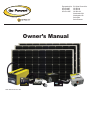
Expansion Kits:
GP-RV-80E
GP-RV-95E
GP-RV-155E
powered by
Owner’s Manual
Solar Extreme shown here
RV Solar Power Kits:
GP-RV-80
GP-RV-95
GP-RV-155
Weekender SW
Weekender HD
Solar Elite
Solar Extreme
Weekender SW
Weekender HD
Solar Elite
Solar Extreme
Table of Contents
RV Installation Parts and Checklist
3
1.0 Installation Overview
4
1.1 How Does the Go Power! RV Solar Kit Work
4
1.2 Warnings
4
1.3 Tools Required (Additional tools may be required)
4
1.4 Weekender SW / Weekender HD / Solar Elite / Solar Extreme Installation
5
2.0 Wiring the Solar Module and Power Cable
5
3.0 Wiring Modules with MC4 Cables
5
3.1 GP RV-80/95/155/Weekender HD/Weekender SW Single Module System/MC4 Junction Box
5
3.2 Solar Elite - Multimodule System/MC4 Junction Box
5
3.3 Solar Extreme - Multimodule System/MC4 Junction Box
2
3.4 GP RV-80E/95E/155E - Expanding to a Multimodule System/MC4 Junction Box
5
3.5 Modules with MC4 Connectors Wired to a Non-Potted Junction Box
5
4.0 Routing Power Cable through the Fridge Vent
6
4.1 Method 1 – Hole in Side of Vent
6
4.2 Method 2 – Through Screen Grid
6
5.0 Mounting the Solar Module
6
5.1 Using the Mounting Feet
6
6.0 Installing The GP-PWM Controller
6
6.1 Mounting The GP-PWM Controller
7
7.0 Connecting to the Battery & Solar Array
7
7.1 Typical Battery Connection
7
8.0 Limited Warranty
7
8.1 General Warranty Issues
8
8.2 Warranty Return Procedure
8
8.3 Additional Information
8
8.4 Out of Warranty Items
9
9.0 System Glossary
9
10.0 Diagrams
11
www.gpelectric.com
GP-RV-80
GP-RV-80E
GP-RV-95
GP-RV-95E
GP-RV-155E GP-RV-155
Weekender SW
Weekender HD
Solar Elite
Solar Extreme
Standard Kits
PART
01. Ring Terminal Battery Connector
02. Power Cable (7 m)
03. Tie Wrap
04. Positive MC4 Parallel Connector
05. Negative MC4 Parallel Connector
06. #10/32 Well Nut
07. #10/32 Well Nut Bolt
08. #10/32 Well Nut Flat Washer
09. #10/32 Well Nut Lock Washer
10. #6 Self-tapping screws
11. Cable clamp
12. ¼” Bolt
13. ¼” Flat Washer
14. ¼” Lock Washer
15. ¼” Nut
16. Mounting Feet
17. Solar module
18. GP-PWM Controller
19. ARM-UNI Mount (Optional) 2
1
6
0
0
4
4
4
4
6
6
4
4
4
4
4
1
1
0
GP-RV-80
GP-RV-80E
GP-RV-95
GP-RV-95E
GP-RV-155E GP-RV-155
Expansion Kits
GP-RV-80/95/155
*Weekender HD or SW
*Solar
Elite
GP-RV-80E/95E/
155E
2
1
6
0
0
6
6
6
6
6
6
6
6
6
6
6
1
1
0
2
1
6
1
1
12
12
12
12
0
0
12
12
12
12
12
2
1
0
0
0
0
1
1
6
6
6
6
0
0
6
6
6
6
6
1
0
0
* The Solar Elite includes: GP-SW2000-12, GP-SWR-B-12, GP-DC Kit4, GPC-45-MAX and GP-TS.
* The Weekender SW includes: GP-SW1500-12, GP-SW-Remote, GP-DC Kit3 and GP-TS.
* The Solar Extreme includes: GP-SW3000-12, GP-SWR-B, GP-DC Kit 5, GPC-75-MAX and GP-TS
Parts Checklist
01
06
11
12
02
Solar Module
17
07
13
03
18
GP-PWM
Controller
08
14
04
09
15
Battery
(not included)
05
19
10
16
(Optional)
www.gpelectric.com
3
Weekender SW
Weekender HD
Solar Elite
Solar Extreme
1.0 Installation Overview
Congratulations on your purchase of a Go Power!TM RV Solar Power Kit. You have chosen a clean, quiet and
sustainable way to provide power to your recreational vehicle. A Go Power!TM RV Solar Power Kit gives you
the ability to dry camp while ensuring your batteries remain fully charged. The Go Power!TMRV Solar Power
Kit allows you to enjoy the luxuries that electricity provides, without a campsite hookup. For simple battery
maintenance or full-time live-aboard power, Go Power!TM RV Solar Power Kits are available in a variety of
sizes and can be installed on RVs, campers, trailers, fifth wheels and motor homes.
1.1 How Does the Go Power!TM RV Solar Power Kit Work
The solar module converts the sun’s energy into DC electricity and this electricity charges the battery. The
battery stores the electricity, similar to a water tank storing water. The battery power may be used at any
time to operate devices connected to the battery. To stop the battery from being overcharged by the solar
module, a solar controller is connected between the two. The GP-PWM-30 controller will disconnect power
from the solar module when the battery is fully charged.
Please read and understand all instructions before installing your new product for the easiest and safest
installation. Before installing the kit, please review the installation diagram included in this Installation
Manual. If you have any doubts as to this kit’s compatibility with your RV, please contact your authorized
Go Power!TM RV Dealer. It is advisable to retain this manual for future reference.
1.2 Warnings
Electrical Safety. Disconnect all power sources before attempting installation. Electricity can be very
dangerous. Installation should be performed only by a licensed electrician or qualified personnel.
Solar Module Safety. Photovoltaic modules generate DC electricity when exposed to sunlight or other light
sources. Contact with the electrically active parts of the module, such as terminals, can result in burns,
sparks and lethal shock whether the module is connected or disconnected.
When modules are connected in parallel, amperages are additive. Consequently, a system assembled from
photovoltaic modules can produce high amperages, which constitute an increased hazard.
Do not touch terminals while module is exposed to light. Cover the module face completely with opaque
material to halt the production of electricity when installing or working with modules or wiring.
Battery Safety. Observe all safety precautions of the battery manufacturer when handling or working around
batteries. When charging, batteries may produce explosive hydrogen gas. Work in a well ventilated area
and use caution when making or removing electrical connections. Ensure wires are disconnected from
their power sources when wiring. Do not expose battery to open flame, cigarettes or sparks. Shield skin
and eyes from battery acid.
Wiring Safety Ensure all connections are tight and secure. Loose connections may generate sparks.
Work safely. Wear protective eyewear and appropriate clothing during installation. Use extreme caution when
working with electricity and when handling and working around batteries. Use properly insulated tools only.
Observe correct polarity at all times. Any contact in reverse polarity, however brief, will cause the regulator
and/or inverter fuse to blow and may damage the unit.
Do not exceed the voltage and current ratings of the regulator. The total current of the solar system is
the sum of the short circuit current of the solar modules in parallel, multiplied by a safety factor of 1.25. The
resulting system current is not to exceed the amperage rating of the regulator. The voltage of the array is
the rated open circuit voltage of the solar modules and is not to exceed 26 volts for a 12 volt system. The
current rating of the solar system is the sum of the Maximum Power Current (lmp) of the solar PV strings in
parallel. The resulting system lmp current is not to exceed 30 A. The voltage of the array is the rated open
circuit voltage (Voc) of the PV array and is not to exceed 56 V. If your solar system exceeds these ratings,
contact your dealer for a suitable regulator alternative.
1.3 Tools Required (Additional tools may be required)
a. Slot Screwdriver
b. # 2 Robertson Square Head Screwdriver
c. Keyhole saw
d. Punch or Awl
e.Pliers
f. Wire Strippers
4
g.
h.
i.
j.
k.
Wire crimpers
Electric hand drill
1/16 and 3/8 inch drill bit
5/16 and 7/16 inch wrench
Sealant www.gpelectric.com
GP-RV-80
GP-RV-80E
GP-RV-95
GP-RV-95E
GP-RV-155E GP-RV-155
Weekender SW
Weekender HD
Solar Elite
Solar Extreme
GP-RV-80
GP-RV-80E
GP-RV-95
GP-RV-95E
GP-RV-155E GP-RV-155
1.4 Weekender SW / Weekender HD / Solar Elite/ Solar Extreme Installation
Refer to specific product manuals included in kits for correct product installation (ex. inverters, chargers and remotes).
2.0 Wiring the Solar Module and Power Cable
Please follow the directions in the appropriate section, depending on which kit you are about to install.
Kit Model
GP-RV-80/95/155/Weekender HD/Weekender SW
Solar Elite
Solar Extreme
GP-RV-80E/95E/155E
Wiring Diagrams (located at the end of the manual)
MC4 Power Cables for RV Kits
Wiring Parallel Modules with MC4 Parallel Connectors
Parallel Wiring Between Standard and MC Junction Boxes
RV System Electrical Layout - RV/Off Grid
RV System Electrical Layout - Manual Power Switching
RV System Electrical Layout - Automatic Power Switching
Manual Section
Section 3.1
Section 3.2
Section 3.3
Section 3.4
Diagram-1
Diagram-2
Diagram-3
Diagram-4
Diagram-5
Diagram-6
3.0 Wiring Modules with MC4 Cables
Note:
This installation guide
does not list all possible
variations of available
solar modules. This
installation guide will
address the assembly of
standard Go Power! RV
Solar Power Kits, which
contain one, two or three
solar modules connected
in parallel for a 12 volt
system. Expander Kits
are available to add solar
modules to an existing
system.
RV Kits with MC4 cables contain a potted or sealed junction box with a positive and negative MC4 connector. This is
referred to as an MC4 junction box. MC4 connectors are either positive or negative and each connector has its
polarity symbol embossed close to the connection point. To extend a cable from an MC4 junction box, a polarity
opposite connector must be used. E.G. a negative connector must plug into a positive connector in order to extend
it. Please remember, the polarity of an MC4 cable wire run is the polarity symbol on the connector closest to the MC4
junction box. It is advisable to attach a polarity sticker to the positive extension cable in order to avoid confusion.
3.1 GP-RV-80/95/155/Weekender HD/Weekender SW
Single Module System/MC Junction Box
RV Kits containing a single module with MC4 cables will be equipped with a single MC4 power cable that has both a male
and female MC4 connection. This cable is meant to be cut in half leaving you with a 25’ cable with a male MC4 and a 25’
cable with a female MC4 connection. Refer to Diagram-1, “MC4 Power Cables for RV Kits.”
3.2 Solar Elite
Multi Module System/MC4 Junction Box
RV Kits containing two modules with MC4 cables via an expansion kit will be equipped with a 50’ MC4 power cable, a
negative MC4 parallel connector and a positive MC4 parallel connector. Refer to Diagram-2, “Wiring Parallel Modules
with MC4 Cables.”
3.3 Solar Extreme
Multi Module System/MC4 Junction Box
RV Kits containing three modules with MC4 cables via two expansion kit will be equipped with a 50’ MC4 power cable, two
negative MC4 connectors and two positive MC4 connectors. Refer to Diagram-2, “Wiring Parallel Modules with MC Cables.”
3.4 GP-RV-80E/95E/155E
Expanding to a Multi Module System/MC4 Junction Box
RV Kits containing two modules with MC4 cables via an expansion kit will be equipped with a 50’ MC4 power cable, a
negative MC4 parallel connector and a positive MC4 parallel connector. Refer to Diagram-2, “Wiring Parallel Modules
with MC4 Cables.”
3.5 Modules with MC4 Connectors Wired to a Non-Potted Junction Box
Please be aware that some modules are equipped with MC4 cables and a fully functioning non-potted Junction Box. In
this case, it is recommended that the MC4 cables be used as described in Section 3. Do not connect the positive and
negative MC4 cables from the same junction box together; this will short circuit the module.
www.gpelectric.com
5
Weekender SW
Weekender HD
Solar Elite
Solar Extreme
GP-RV-80
GP-RV-80E
GP-RV-95
GP-RV-95E
GP-RV-155E GP-RV-155
Refrigerator
Vent Cover
4.0 Routing Power Cable through the Fridge Vent
Solar
Module
Locate the refrigerator vent on the roof of the RV. Remove vent cover to gain access to the duct opening.
Refer to Figure 1. Retain vent-fastening hardware.
4.1 Method 1 – Hole in Side of Vent
Drill a hole through the side of the vent (5/8” hole). Insert a rubber grommet (not included) into the hole.
Insert the power cable (already wired to the solar module) through the hole and carefully route it to the
battery. Be certain to leave enough slack to allow cable routing from module to vent along desired path.
4.2 Method 2 – Through Screen Grid
1. Thread power cable (already wired to solar module) carefully through the screen and into opening.
Enlarge screen grid hole if necessary.
2. Avoid strapping the power cable to existing wire between the module and the battery. Allowing a few
inches of space between the power cable and existing wire will lessen the chance of voltage loss
through thermal conduction. Use cable clamps with the # 6 self-tapping screw and/or tie wraps every
few feet along RV roof and interior route to battery.
3. Ensure all penetrations into the RV roof are watertight. Use an appropriate sealant as recommended
by your RV Dealer to seal holes wherever necessary.
4. Replace vent cover.
Method 2
Cable
Clamps
Method 1
Vent
Screen
Figure 1
Caution:
The screen may have sharp edges or
burrs.
5.0 Mounting the Solar Module
The solar modules may be horizontally mounted to the roof using the included mounting feet. An optional
adjustable roof mount (ARM-UNI) is also available from Go Power!.
5.1 Using the Mounting Feet
1. Assemble the mounting feet onto the ends of the solar module using the 1/4” bolts, washers and nuts
as shown in Figure 2.
2. Tighten nuts securely using a 7/16” wrench.
3. Place the module in a location that follows the criteria listed here:
•
Select a location where the mounting surface is at least 1/2” thick and strong enough to support mounting hardware, the solar module and wind loads
•
Minimize distance between the location of the solar module and the location where the power cable will enter the vehicle to connect to the battery
•
Place the module lengthwise along the roof to reduce wind loading on vehicles (if applicable)
•
Avoid internal wiring when selecting the spots for drilling the four mounting holes
•
Ensure obstacles, such as air conditioners, will not shade the solar module
1/4’ Bracket
Bolt
Mounting
Foot
8.
If you are installing on a rubber roof with plywood underneath, it is acceptable to use wood screws
instead of the well-nuts that are provided.
6.0 Installing The GP-PWM-30 Solar Controller
6
The GP-PWM -30 is included in all Go Power! RV Kits mentioned in this manual except for the
Expansion Kits.
www.gpelectric.com
1/4’ Lock
Washer
1/4” Nut
Figure 2
Solar
Module
5. Use the appropriate sealant as recommended by your RV Dealer to ensure a watertight installation.
7. Insert screws with lock washers and tighten. Do not overtighten.
1/4” Flat
Washer
RV
Roof
Note: Place module so that you have room to expand the current system if needed.
4. Mark the mounting hole locations by using a pencil to trace through the holes in the mounting feet.
Drill mounting holes only one inch deep with a 3/8” drill bit.
6. Gently insert the well-nuts into the drill holes so that only the topmost flange part remains above the
roofline. Be careful not to push well-nuts through the holes.
Solar
Module
RV
Roof
Mounting
Foot
Figure 3
Weekender SW
Weekender HD
Solar Elite
Solar Extreme
Solar
Controller
GP-RV-80
GP-RV-80E
GP-RV-95
GP-RV-95E
GP-RV-155E GP-RV-155
The GP-PWM-30 provides the necessary protection for the RV battery system. A condensed version
of the installation instructions appear below. However, please read the full installation manual included
with the GP-PWM-30 Solar Controller.
1. Disconnect or cover the solar modules and disconnect the batteries before commencing the GPPWM-30 wiring.
Positive
Connection
Negative
Connection
Single 12 Volt Battery
12 Volt Configuration
Figure 5
2. Run the solar module power cable to the location of The GP-PWM-30. Do not connect the wires
to the controller or the batteries. Identify the polarity of the wires located on the battery and
solar module (positive and negative). Use coloured tape or mark wire ends with tags. Contacting
the leads of the controller in reverse polarity, however brief, will cause the controller to go into lock
out mode and the solar controller will need to be reset.
3. Wire the controller according to the terminal identification on the back of controller starting with the
battery connections. Tighten the connections and then set the battery type on the controller (see
controller manual for instruction). Then connect the solar module and tighten the connections.
4. Read The GP-PWM-30 Manual prior to installing.
6.1 Mounting The GP-PWM-30 Controller
The GP-PWM-30 should be mounted in a location relatively close to the battery, but easily seen for
monitoring system operation. Wires must be run from the solar module to the controller and then to the
battery. The GP-PWM-30 is designed to be flush mounted on the side of a cabinet or wall where the
wiring can be accessed from the back. Allow two to three inches behind the unit. The controller should
be mounted indoors, in a dry location.
Solar
Controller
1. Select a suitable location for the installation of the controller. Run the power cable from the solar
module to the location selected.
Negative
Connection
Positive
Connection
2. Use the template included in the GP-PWM-30 Manual to mark the four mounting holes and the “cutting
line for flush mounting”. Drill the mounting holes. Use a keyhole or jig saw to cut along the rectangular
outline you marked.
3. Wire the controller as shown in the GP-PWM-30 Manual. Use the leftover power cable to connect the
controller to the batteries.
4. Mount the controller to the wall using the four wood screws provided. Ensure the back of the controller
is protected from damage by any object.
Two 12 Volt Batteries
12 Volt Parallel Configuation
Figure 6
7.0 Connecting to the Battery & Solar Array
It is recommended to connect directly to the battery wherever possible. You can also connect to the
converter charger where the battery positive and negative wires connect to the converter.
1. Clean all corrosion from battery terminals before proceeding. Crimp ring terminals onto the negative
and positive wires of the power cable to be attached to the battery.
Solar
Controller
2. Attach the negative (black) wire’s 3/8” ring terminal to the RV battery. Check all electrical connections
and apply a protective coating to battery terminals.
7.1 Typical Battery Connection
Negative
Connection
Positive
Connection
1. Single 12 Volt battery connection (See Figure 5)
2. Parallel 12 Volt battery connection (See Figure 6)
3. 6 Volt series battery connection (See Figure 7)
8.0 Limited Warranty
Two 6 Volt Batteries
12 Volt Series Configuation
Figure 7
1. Go Power! warrants the Go Power!TM RV Solar Power Kit for a period of one (1) year from the date
of shipment from its factory. This warranty is valid against defects in materials and workmanship for
the one (1) year warranty period. It is not valid against defects resulting from, but not limited to:
•
Misuse and/or abuse, neglect, or accident
•
Exceeding the unit’s design limits
•
Improper installation, including, but not limited to, improper environmental protection and improper hook-up
www.gpelectric.com
7
Weekender SW
Weekender HD
Solar Elite
Solar Extreme
•
•
Acts of God, including lightning, floods, earthquakes, fire, and high winds
Damage in handling, including damage encountered during shipment
2. This warranty shall be considered void if the warranted product is in any way opened or altered. The
warranty will be void if any eyelet, rivets, or other fasteners used to seal the unit are removed or
altered, or if the unit’s serial number is in any way removed, altered, replaced, defaced or rendered
illegible.
3. The one (1) year term of this warranty does not apply to equipment where another limited warranty is
available. This may include but is not limited to, the solar controller five (5) years, the solar modules
twenty-five (25) years and the inverter: modified sine wave inverter one (1) year, pure sine wave
inverter two (2) years.
8.1 General Warranty Issues
1. Go Power!TM cannot assume responsibility for any damages to any system components used in
conjunction with Go Power!TM products, nor for claims of personal injury or property damage resulting
from the use of Go Power!TM products or the improper operation thereof or consequential damages
arising from the products or use of the products.
2. Go Power!TM cannot guarantee compatibility of its products with other components used in conjunction
with Go Power!TM products, including, but not limited to, solar modules, batteries, and system
interconnects and such loads as inverters, transmitters and other loads which produce “noise” or
electromagnetic interference, in excess of the levels to which Go Power! products are compatible.
3. The purchaser’s exclusive remedy for any and all losses or damages resulting from the date of sale
of this product including, but not limited to, any allegations of breach of warranty, breach of contract,
negligence or strict liability, shall be limited, at the option of Go Power!TM, to either the return of the
purchase price or the replacement of the particular product for which claim is made and proved. In
no event shall Go Power!TM be liable to purchaser or purchaser’s customers or to anyone else for any
punitive, special, consequential, incidental or indirect losses or damages resulting from the sale of
the product, whether based upon loss of goodwill, lost profits, work stoppages, impairments of other
goods, breach of contract, or otherwise.
4. This warranty supersedes all other warranties and may only be modified by statement in writing,
signed by Go Power!TM.
5. Warranty terms effective as of July 4, 2005.
8.2 Warranty Return Procedure
Visit www.gpelectric.com to read the “frequently asked questions” section of our website to troubleshoot
the problem. If trouble persists:
1. Call your Go Power!™ Technical Support team (1-866-247-6527).
2. Return defective product to place of purchase.
8.2.1 End Users
Contact your sales representative or Dealer and discuss the problem. Often the sales representative can
troubleshoot common scenarios. If applicable, warranty will be handled between the End User and the
Dealer. Go Power!TM will only accept returned items from an End User as a last resort. If you are unable
to contact the Dealer, or the Dealer refuses to provide service, please contact Go Power!TM directly.
8.2.2 Dealers
Dealers will handle warranty either through their supplier or Go Power!TM, depending on where the product
was purchased from.
8.2.3 Units bought directly from Go Power!
The customer will return the product, freight prepaid, to Go Power! You must obtain a Return Material
Authorization (RMA) number from Go Power!TM before returning a product. The RMA number MUST be
clearly indicated on the outside of the box. Items received without an RMA number will be refused.
8.3 Additional Information
Unless approved by Go Power! management, all product shipped collect to Go Power! will be refused.
Test items or items that are not under warranty, or units that are not defective, will be charged a minimum
bench charge of ($50.00 US) plus taxes and shipping. A 15% restocking charge will be applied on goods
returned and accepted as “new” stock.
8
www.gpelectric.com
GP-RV-80
GP-RV-80E
GP-RV-95
GP-RV-95E
GP-RV-155E GP-RV-155
Weekender SW
Weekender HD
Solar Elite
Solar Extreme
GP-RV-80
GP-RV-80E
GP-RV-95
GP-RV-95E
GP-RV-155E GP-RV-155
8.4 Out of Warranty Items
Go Power! electronic products are non-repairable, Go Power!TM does not perform repairs on its
products nor does it contract out those repairs to a third party. Go Power!TM does not supply schematics
or replacement parts for any of its electronic products.
9.0 System Glossary
Ampere A unit of electrical current. Designates the number of electrons flowing per second through a
conductive material.
Ampere-Hour (Ahr or amp hour): A unit of energy, typically referring to battery capacity. One ampere
of current flowing for one hour.
Azimuth of the Sun: The angular measure between due south and the point on the horizon directly
below the sun.
Array: A number of photovoltaic modules electrically connected to produce a single electrical output.
Angle of Incidence: The angle between a ray of sunlight striking a surface and a line perpendicular to
that surface. Rays perpendicular to a surface have a zero angle of incidence.
Battery: Two or more electrochemical cells connected to provide energy storage. May be used to designate
one cell. PV system batteries may be “sealed” or “flooded”.
Blocking Diode: A diode application that prevents a battery from discharging through the array at night
or if the array becomes shaded. Most charge controllers are equipped with a blocking diode.
Charge Controller (regulator): The PV system component that controls the battery’s state of charge. It
may also provide other system control functions. Also known as a regulator.
Charge Rate: The current applied to a battery to restore its energy capacity. The battery manufacturer
will usually have a recommended charge rate for their product. The rate is typically 10 – 20 percent of the
amp hour capacity at the 20-hour rate.
Current: DC or Direct Current is the type of electron flow provided by a battery or solar cell, which flows
in one direction. The unit for current is ampere or amp for short and designated by the letter A.
Cycle: One battery cycle equals one discharge and one charge.
Deep Cycle Battery: Batteries that are designed to discharge as much as 80% of their capacity as
opposed to engine-starting or shallow cycle batteries which are designed for heavy cranking but will not
stand up to repeated deep discharges.
Depth of Discharge: A measure of how much energy has been withdrawn from a battery, expressed as
a percentage of full capacity. A 100 Ahr battery from which 30 Ahr has been withdrawn has undergone a
30% depth of discharge (DOD). This term is the inverse of state of charge (SOC); the example battery
would be at 70% SOC.
Diode: A semi-conductor device that allows current to flow in one direction only. “Blocking diodes” and
“isolation diodes” are standard diodes that have specific applications.
Electrolyte: Battery acid.
Equalization: The process that equalizes the specific gravity of all the cells in a battery by means of a
controlled overcharge that breaks down sulfation on the battery plates. Most inverter/chargers and some
charge controllers are equipped with this feature. Usually performed only on flooded batteries.
Flooded or Wet Cell Batteries: The most common type of PV battery. Battery caps may be removed
to expose the electrolyte inside the battery. Need proper ventilation due to gassing and may need to be
topped up with distilled water at regular intervals.
Grid-Connected: A power system interconnected with the grid (or mains) of the local electric utility. Also
referred to as utility-interactive or grid-tie.
www.gpelectric.com
9
Weekender SW
Weekender HD
Solar Elite
Solar Extreme
Hybrid System: A power system consisting of two or more energy sources (e.g., a PV array and a wind
generator).
Hydrometer: A device used to measure the specific gravity (SG) of the electrolyte in a flooded battery.
A very accurate way to see the true charge of a battery.
Insolation: The solar energy received at a place over a given period. May be expressed as sunhours
per day, watts per square meter per hour, or any number of other units.
Inverter: A device that converts DC electricity to AC.
Isolation Diode: A diode application that prevents one segment of an array from interacting with another
array segment. Usually used in situations where two parts of an array are facing in different directions
therefore one part of an array may experience shading while the other does not. Prevents array energy from
flowing backwards through a low voltage string of the array. May also serve the function of blocking diode.
Maximum Power (peak power): The point of a solar array, panel or module output where the product
of Imp and Vmp (Pmax, measured in watts) is maximized. The points used to calculate Pmax are Imp
(current @ max power) and Vmp (voltage @ max power).
Module: A number of solar cells electrically connected, and protected from the environment usually by an
aluminum frame covered with a pane of glass. A module is self-contained and not sub dividable, therefore
providing a single electrical output.
NOCT (Nominal Operating Cell Temperature): the temperature at which PV cells in a module operate
under Standard Operating Conditions (SOC), which are: irradiance of 0.8 kW/m2, 20ºC ambient
temperature, and average wind speed of 1 m/s, with the wind oriented parallel to the plane of the array,
and all sides of the array fully exposed to the wind.
Open-Circuit Voltage (Voc): Refers to a photovoltaic device’s voltage potential when it is disconnected
from the rest of the PV system.
Panel: A group of photovoltaic modules (or single module) mechanically mounted on a single frame.
Parallel Connection: Electrical connection where the positive terminals of a number of devices are
connected together, as are their negative terminals. The output voltage is usually limited to the device
with the lowest voltage and the total current is the sum of the current of all the devices.
Photovoltaic (PV): Capable of producing a voltage when exposed to radiant energy, especially light.
Regulator: See “Charge Controller” definition.
Sealed Batteries: Electrolyte will not spill out and gassing is kept to a minimum. A sealed battery is
maintenance free and may be installed in several orientations.
Series Connection: Electrical connection where the positive terminal of one device is attached to the
negative terminal of the next in a series string; in this connection, the string voltage is the sum of the
device voltages and the string current is limited to the current of the least productive device in the string.
Short-Circuit Current (Isc): Refers to a PV device’s current output when the positive terminal is directly
connected to the negative terminal.
Specific Gravity: In relation to a flooded battery, it is the density of the “electrolyte” compared with the
density of water thereby measuring the battery state of charge.
Standard Operating Conditions (SOC): A set of reference PV device measurement conditions consisting
of irradiance of 0.8 kW/m2, 20ºC ambient temperature, and average wind speed of 1m/s, with the wind
oriented parallel to the plane of the array and all sides of the array fully exposed to the wind.
Standard Test Conditions (STC): A set of reference PV device measurement conditions consisting of
irradiance of 1 kW/m2, AM 1.5 and 25ºC cell temperature.
10
www.gpelectric.com
GP-RV-80
GP-RV-80E
GP-RV-95
GP-RV-95E
GP-RV-155E GP-RV-155
Weekender SW
Weekender HD
Solar Elite
Solar Extreme
GP-RV-80
GP-RV-80E
GP-RV-95
GP-RV-95E
GP-RV-155E GP-RV-155
Standalone System: A power system not connected to the utility grid (mains.) Sometimes referred to
as an autonomous system.
State of Charge: The percentage of energy in a battery referenced to its nominal full capacity.
Sulfation: The formation of lead sulfate crystals on the plates of a lead-acid battery. Normally used to
refer to large sulfate crystals, rather than small crystals formed in normal battery operation. The sulfate
on the plates of a battery will harden if left in a partially charged state, causing reduced battery capacity
and shortening the life of the battery. If caught in time, “equalization” will remove the buildup of sulfation.
Voltage: The electrical potential between two points. Voltage is analogous to water pressure in that it
pushes the electrons or current through a conductor. The unit for voltage is volt and designated by the
10.0 Diagrams
MC4 Power Cables for RV Kits
Wiring Parallel Modules with MC4 Parallel Connectors
Parallel Wiring Between Standard and MC4 Junction Boxes
RV System Electrical Layout - RV/Off Grid
RV System Electrical Layout - Manual Power Switching
RV System Electrical Layout - Automatic Power Switching
www.gpelectric.com
Diagram-1
Diagram-2
Diagram-3
Diagram-4
Diagram-5
Diagram-6
11
Weekender SW
Weekender HD
Solar Elite
Solar Extreme
GP-RV-80
GP-RV-80E
GP-RV-95
GP-RV-95E
GP-RV-155E GP-RV-155
Diagram 1
MC4 Power Cabels For RV Kits
Positive MC4
Junction Box
Connection - Male
Negative MC4 Junction
Box Connection - Female
The MC4 power cable is usually the final connection
between the solar array and the solar controller. If it has
not already been done, cut the MC power cable into two
pieces so that there is a positive conductor cable and
negative conductor cable.
1. Cover the solar module(s) with an opaque material.
Attach the appropriate MC4 power cable conductor to the
positive and negative connectors of the MC4 junction box.
If you have more than one module, refer to the specific
diagram for wiring a parallel MC4 connection.
Positive MC4
Cable Conductor
Negative MC4
Cable Conductor
Positive Polarity Label
2. Run the positive and negative MC4 cable conductors
from the solar array to the solar controller. Attach a positive
polarity label to the end of the positive conductor. If the
positive conductor needs to be shortened and the polarity
label is removed, remember to re-label it as both positive
and negative conductors look exactly the same. Leave a
few feet of cable at the solar controller in case of future
adjustment.
Note: solar module junction box and MC4 cables many not
be exactly as shown.
Cut 50’ wire in
half to make
two 25’ cables
12
www.gpelectric.com
Weekender SW
Weekender HD
Solar Elite
Solar Extreme
GP-RV-80
GP-RV-80E
GP-RV-95
GP-RV-95E
GP-RV-155E GP-RV-155
Diagram 2
Wiring Parallel (2) Modules with MC4 Parallel Connectors
Negative MC4 Parallel Connector - Female
MC4 Extension Cable to Solar Controller or Combiner Box
Positive MC4 Parallel Connector - Male
MC4 Cable Connections for 2 Parallel Modules
E.G. Two 12V modules at 12V
Note: solar module junction box and MC4 cables many not
be exactly as shown.
MC4 Parallel - Male
MC4 Parallel - Female
www.gpelectric.com
13
Weekender SW
Weekender HD
Solar Elite
Solar Extreme
GP-RV-80
GP-RV-80E
GP-RV-95
GP-RV-95E
GP-RV-155E GP-RV-155
Diagram 3
Parallel Wiring Between a Standard Junction Box and an MC4 Cable Junction Box
Negative MC4 Parallel Connector - Female
Existing MC Power Cable
to Solar Controller
MC4 Extension Cable
(MC4 Output 10)
Positive MC4 Parallel Connector - Male
Parallel Wiring Between a Standard Junction Box and an Existing MC4 Cable Junction Box
Note: solar module junction box and MC4 cables many not
be exactly as shown.
Existing Power
Cable to Solar
Controller
14
MC4 Extension Cable (MC4 Output 10)
MC4 Parallel - Male
www.gpelectric.com
MC4 Parallel - Female
Weekender SW
Weekender HD
Solar Elite
Solar Extreme
GP-RV-80
GP-RV-80E
GP-RV-95
GP-RV-95E
GP-RV-155E GP-RV-155
Diagram 4
RV Electrical Layout - RV / Off Grid
Charge
Controller
Solar
Module
All positive conductors connected to the battery
should be equipped with the circuit protection rated
to the wire size used.
Loads
Battery
AC
Panel
Converter
If the inverter supplies power to the AC panel which provides
power to a converter, the resulting battery loop will quickly drain
the batteries.
Disconnect the converter entirely from the system via a breaker or
physically disconnecting the wires.
Inverter
Shore Power Cable
Usually the converter with circuit protection is rewired to connect to
the utility power side of the system, if utility power is available.
Diagram is recommended wiring only. Compliance
with governing electrical code is assumed.
In no event will Carmanah be liable to any party or
for any direct, indirect, special or other consequential
damages resulting from use of this diagram.
www.gpelectric.com
15
Weekender SW
Weekender HD
Solar Elite
Solar Extreme
GP-RV-80
GP-RV-80E
GP-RV-95
GP-RV-95E
GP-RV-155E GP-RV-155
Diagram 5
RV Electrical Layout - Two AC Power Sources
No Transfer Switch - Manual Switching
Solar
Module
Charge
Controller
Disconnect the converter entirely from the system via a
breaker or physically disconnecting the wires.
Usually the converter with circuit protection is rewired to
connect to the utility power side of the system, if utility power
is available.
Converter/
Battery
Charger
All positive conductors connected to
the battery should be equipped with
the circuit protection rated to the
wire size used.
Battery
If the inverter supplies power to the AC panel which provides
power to a converter, the resulting battery loop will quickly
drain the batteries.
Loads
AC
Panel
Shore Power Cable
Inverter
In no event will Carmanah be liable to any party or
for any direct, indirect, special or other consequential
damages resulting from use of this diagram.
16
In the absence of a transfer switch, the AC panel
connection is physically unplugged from inverter
and plugged into utility power and vice versa.
www.gpelectric.com
Utility Power or
Generator
Diagram is recommended wiring only. Compliance
with governing electrical code is assumed.
Weekender SW
Weekender HD
Solar Elite
Solar Extreme
GP-RV-80
GP-RV-80E
GP-RV-95
GP-RV-95E
GP-RV-155E GP-RV-155
Diagram 6
RV Electrical Layout - Two AC Power Sources
with Automatic Transfer Switch
Charge
Controller
Solar
Module
All positive conductors connected
to the battery should be equipped
with the circuit protection rated to
the wire size used.
Inverter
In no event will Carmanah be liable to any party or
for any direct, indirect, special or other consequential
damages resulting from use of this diagram.
Disconnect the converter entirely from the system via a breaker
or physically disconnecting the wires.
Usually the converter with circuit protection is rewired to connect
to the utility power side of the system, if utility power is available.
Converter/
Battery
Charger
Battery
If the inverter supplies power to the AC panel which provides
power to a converter, the resulting battery loop will quickly drain
the batteries.
Loads
AC
Panel
Transfer
Switch
Utility Power or
Generator
Diagram is recommended wiring only. Compliance
with governing electrical code is assumed.
www.gpelectric.com
17
Weekender SW
Weekender HD
Solar Elite
Solar Extreme
powered by
© 2012 GO POWER!™ By Carmanah Technologies
MOBI_MAN_GP-RV Install Kit and Systems_vA1.indd
18
www.gpelectric.com
GP-RV-80
GP-RV-80E
GP-RV-95
GP-RV-95E
GP-RV-155E GP-RV-155