1
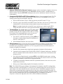
EchoStar Technologies Corporation PRODUCT LAUNCH BULLETIN: ViP622 DVR™ Introduction ViP622 DVR is the first dual-tuner, two-TV DISH Network receiver compatible with the MPEG-4 compression standard. ViP622 DVR supports high definition (HD) for TV1, provides DVR functionality for both TV1 and TV2 and includes one digital off-air tuner. Refer to Quick Facts: ViP622 DVR for additional information. Considerations TV1 video is provided by two HD video outputs (HDTV digital audio/video for connection to HDMI HDTVs and Component - YPbPr) and two standard definition (SD) video outputs (S-Video and RCA). TV1 audio is provided by either RCA left/right or Digital Audio output. The user has the option to select which TV1 video output (HD or SD) to synchronize with the TV1 audio (see Installation Instructions on page 3 for more information). An off-air tuner is included which receives only digital off-air channels, not analog off-air channels. To watch analog off-air channels, the TV’s tuner must be used. The Agile Modulated output supports a modulated channel carrying TV1 programming in addition to the modulated channel which carries TV2 programming. This feature provides the option to view TV1 or TV2 programming on any connected remote TV. When the system is locked, a password must be entered to enable the TV1 Out. Refer to Connecting to the Remote TVs (TV1 or TV2) in Chapter 12 of the User’s Guide or Quick Facts: TV1/TV2 Agile Output for additional information. ViP622 DVR has two USB 2.0 ports, one on the front panel and one on the back panel. These ports can be used for Multimedia features similar to those of a DISH Player-DVR 942, including transferring of recorded events to the PocketDISH Portable Media Player and Recorder. DISH on Demand features are supported and are accessed by pressing the DVR button and selecting “Movies & More”. One Ethernet port is included on the back panel and is reserved for future use. Initial Installation Tips Software for the ViP622 DVR is not available from the 110° satellite location. To download software for the ViP622 DVR, you must have signal from one of the following satellite locations: 119°, 61.5°, 148°, 121°, or 105°. Use Remote Control 1 (IR) to perform the initial receiver installation. Similar to the DISH Player-DVR 942, Remote Control 2 (UHF Pro) is preset at the factory to a random remote address between 1 and 16, and is set up to control the receiver in a later step of the installation. See Installation Instructions on page 3. Remote Control 2, indicated with the blue TV2 key, has a small A/B switch under the battery cover that changes the remote to a different UHF frequency. The default setting for this switch is the “A” position, and should only be changed to avoid UHF interference from other devices. Changing the frequency between A or B requires re-synchronizing the receiver to the remote on the System Information screen. Default output resolution for the HD outputs is 480p. During installation, change the resolution to 720p or 1080i as appropriate for the connected HDTV. Do not connect a phone line to the Ethernet port. All phones in the household will stop functioning if a phone line is accidentally plugged into this port. The default mode of the ViP622 DVR is dual mode, supporting independent viewing on two TVs. The default mode for TV1 audio synchronization is to synchronize with the HD video outputs. 143884 1 EchoStar Technologies Corporation Installation Instructions for ViP622 DVR Follow the steps below to install a ViP622 DVR. Detailed instructions for some steps below are found in the receiver User’s Guide. Note: All current LNBF and switch configurations are supported by the ViP622 DVR in factory software. A DISH Pro Plus Separator can be used if the receiver is directly connected to a DISH Pro Plus LNBF or switch. Note: Do not use Remote Control 2 to operate the ViP622 DVR until after the software download. Install batteries in Remote Control 1. 1. Connect ViP622 DVR to HDTV (TV1): Connect the receiver to the nearby HDTV using the TV1 audio/video connections. Attach the UHF remote antenna and an active phone line to the ViP622 DVR. Power on the HDTV and satellite receiver using the front panel power buttons, and confirm you can see a picture from the receiver. a. If you cannot see a picture, ensure the HDTV is on the correct input and capable of displaying 480p, which is the default resolution of the ViP622 DVR through the HD outputs. See the user’s guide that came with the HDTV for instructions. b. If you still cannot see a picture, temporarily connect the RCA-type TV1 outputs to the nearby HDTV, and change the HDTV to the appropriate input to see a picture. 2. Mount dish: Assemble and mount the satellite dish(es) using standard dish installation methods and instructions. 3. Peak dish (peaking meter): If you plan to use a peaking meter to peak the dish(es): a. Peak each dish for maximum signal strength. b. Connect all LNBFs and switches together using the instructions for these devices, and connect both of the ViP622 DVR’s Satellite In ports to the same switch, LNBF, or DISH Pro Plus Separator. Attach the two blue Satellite In stickers from the receiver User’s Guide to the two Satellite In cables near the receiver. 4. Peak dish (using ViP622 DVR): If you plan to use the receiver’s Point Dish/Signal screen to peak the LNBF(s): a. Connect each LNBF to be peaked directly to the Satellite In connections. If needed, you can temporarily use a DISH Pro compliant splitter (for peaking only) to connect one satellite signal cable to both tuners. Run a Check Switch test on each LNBF used for peaking. Peak each LNBF using the Point Dish screen. b. Connect all LNBFs and switches together using the instructions for these devices, and connect both of the ViP622 DVR’s Satellite In ports to the same switch, LNBF, or DISH Pro Plus Separator. Attach the two blue Satellite In stickers from the receiver User’s Guide to the two Satellite In cables near the receiver. 5. Check Switch: Run a Check Switch test. Make sure that the results show the correct LNBF(s), switch(es), and satellite locations, and that the results match for satellite tuner 1 and 2. 6. Software download: Take a software download by selecting Cancel or Done from the Point Dish/Signal screen and selecting Yes on the next screen. The software download takes between 15 and 30 minutes to complete. 143884 2 EchoStar Technologies Corporation 7. Address ViP622 DVR to Remote Control 2: After the software download is complete, the receiver displays a pop-up message asking you to press RECORD on Remote Control 2. Install batteries in Remote Control 2 and press RECORD, which places the receiver and Remote Control 2 on the same remote address. 8. Customize ViP622 DVR’s HDTV Picture Settings: Refer to Connecting to the Nearby TV (TV1) in Chapter 12 of the User’s Guide. Go to the HDTV Setup menu by pressing MENU on the remote, selecting System Setup (6), then HDTV Setup (8). a. Select an HD resolution (720p or 1080i) supported by the HDTV under TV Type. b. Select the correct Aspect Ratio for the HDTV, then select Done. See the user’s guide that came with the HDTV if you do not know what resolution or aspect ratio setting to use. Note: If you had to temporarily connect RCA-type outputs to get a picture on the HDTV, change the HDTV back to the correct input and resolution for the receiver’s HD output. 9. TV1 Audio Sync: The default setting is for TV1 audio outputs to be synchronized with the HD video outputs. If the customer primarily uses the SD video outputs (S-Video, RCA or coaxial) for viewing of TV1 programming, the receiver can be set to synchronize the TV1 audio to the SD video outputs. a. Go to the TV1 Audio Sync menu by pressing MENU on the remote, selecting System Setup (6), Installation (1), then TV1 Audio Sync (7). b. Select Standard Definition, then select Done. 10. Off-Air Antenna: Refer to Connecting Off-Air Antenna/Cable TV in Chapter 12 of the User’s Guide. Live digital off-air broadcasts can only be viewed at the TV1 location. Recorded digital off-air broadcasts can be played back at either TV1 or TV2. If you plan to connect an off-air antenna for reception of digital off-air channels: a. Peak the off-air antenna using a signal meter appropriate for digital off-air broadcasts. b. Connect the off-air antenna to the ViP622 DVR’s 8VSB TV Antenna/Cable In port. Attach the black TV Antenna/Cable In sticker from the receiver User’s Guide to the off-air antenna cable near the receiver. c. Go to the Local Channels menu by pressing MENU on the DISH Network remote, selecting System Setup (6), then Local Channels (9). You can select Scan Locals to let the receiver find digital off-air channels or Add Locals to add them manually. d. To display Local Satellite Channels in the EPG by broadcast number, select Sat Locals, select Enable, then select Done. e. When you are finished adding digital off-air channels, select Done. Note: The ViP622 DVR supports display of only digital off-air channels in the EPG. Analog off-air channels can still be viewed using the TV’s tuner. For TVs connected using Ch 21-69 Out (TV1/TV2 Agile Output), the off-air antenna needs to be connected to the TV distribution equipment. The FCC requires that you install appropriate equipment between the off-air antenna/cable and the satellite TV receiver to prevent you from accidentally retransmitting DISH Network programming. The Super Home Node is the only EchoStar-approved device supporting this type of installation. See the FCC Compliance section in the Appendix of the User’s Guide for additional information. 143884 3 EchoStar Technologies Corporation 11. ViP622 DVR to TV2(s): a. Connect the remote TV(s) to an existing wall cable outlet and power on the TV(s). b. Find three side-by-side channels on the remote TV(s) that show no video (they show snow, static, etc. instead). These three channels must be in the 21-69 range if your TV(s) will be set in Air Mode or in the 73-125 range if using Cable Mode. c. Tune the remote TV(s) to the middle channel of the side-by-side channels you found, and note the mode the TV is in. d. Connect the cable from the CH 21-69 Out port to the existing wall cable outlet. Attach the yellow CH 21-69 Out sticker to this cable near the receiver. e. Back at the nearby HDTV, go to the Modulator Setup menu by pressing MENU, selecting System Setup (6), Installation (1), then Modulator Setup (5) using Remote Control 1. Set the TV2 OUT mode and channel the same as you set the remote TV(s), then select Done. f. Verify that you have a good picture on the remote TV(s). If not, you may need to change the cable connections on the splitter that sends the TV signal throughout the house. Make sure that the CH 21-69 Out port is connected to the input of the splitter, and that the remote TV(s) is connected to an output of the splitter. Attach the TV2 sticker on or close to the remote TV(s), and write on the sticker which channel the TV needs to be on to view satellite programming. g. In the How to Watch TV on TV2 section of the included TV2 Quick Reference Guide, write down the TV2 Out channel, and if applicable, the VCR channel and whether the VCR needs to be on or off. Note: To display TV1 programming on the “Ch 21-69” output, follow the steps above and enable TV1 Out using the Modulator Setup screen, setting TV1 Out to the same mode and at least two channels away from TV2 Out. If TV1 has locks set, you will need to enter the password to enable TV1 Out. Set the remote TV(s) to the same mode and channel as TV1 Out. Refer to Connecting to the Remote TVs (TV1 or TV2) in Chapter 12 of the User’s Guide for additional information. 12. Program TV mode and Limited Mode as needed: Program each remote control to the TV. If you want to program the TV in Limited Mode to send only power and volume commands, use the steps listed in Controlling Other Components in Chapter 10 of the User’s Guide. 13. Recover button: Program the RECOVER button for Remote Control 2 to the same channel as each remote TV, using the steps listed in Controlling Other Components in Chapter 10 of the User’s Guide. Confirm that the RECOVER button works for each remote and TV. 143884 4