1
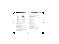
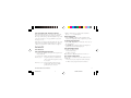
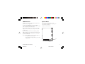
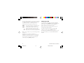
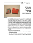
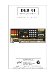
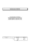
8003
1/8 DIN
Temperature Controller
❒ USER’S MANUAL
Issue Date
April 1994
8003 Cover
0037-75212
1
4/27/06, 2:26 PM
Contents
Model Identification .................................................................................................................................... Page ii
Dimensions and Panel Cutout ............................................................................................................................1
Wiring ...........................................................................................................................................................................2
Hardware Setup .......................................................................................................................................................3
Configuration Mode ...............................................................................................................................................4
Operator Mode .........................................................................................................................................................9
Error Messages ..................................................................................................................................................... 12
Warranty and Return ........................................................................................................................................... 14
Chromalox 8003 User's Manual
8003 TOC
i
1
4/27/06, 2:23 PM
Model Identification
Model
8003
1/8 DIN Temperature Controller
Code
Output 1 - Heat or Cool
1
SPDT Relay, 3 Amps at 250 Vac (Resistive) or
SSR Drive, 14V @ 20mA, Jumper Selectable
Code
Output 2 - Cool or Alarm
1
Relay, 2 Amps at 250 Vac (Resistive) or
SSR Drive, 14V @ 20mA, Jumper Selectable
Code
Options
0
1
None
Alarm #2, 2 Amps at 250 Vac (Resistive load)
Code
Power Supply
3
5
8003 -
1
1
1
ii
8003 TOC
3
100/240 Vac
24 Vac/dc
Code
0
Add to complete model number
0
Typical Model Number
Chromalox 8003 User's Manual
2
4/27/06, 2:23 PM
1.77
(45)
Dimensions in inches (mm in parenthesis)
3.62
(92)
5.1
(125)
Chromalox
2.4
(60)
PV
SP
0.5
(12.8)
3.5
(89)
3.8
(96)
MAIN AL1 AL2 SMRT
COOL HB
FUNC
SMRT
1.9
(48)
Chromalox 8003 User's Manual
8003 Manual
1
1
4/27/06, 2:24 PM
12
1
PWR
Line
Wiring
13
TC+
TC
-
15
+
OUT2
RELAY
AL1/COOL
16 NO
17
C
6
OUT1
SSR
18
-
7
19
+
8
20
C
OUT1
RELAY
21 NO
22 NC
RTD
OUT2
SSR
AL1/COOL
14
3
TC-
4
Warnings:
• When a relay output is used to drive an inductive
load, it is suggested that you connect an external
snubber network (RC) across the terminals in
accordance with the following table (or use
Chromalox snubber P/N 0149-01305):
Load
C
Current (mA) (mF)
5
<40 mA
<150 mA
<0.5 A
0.047
0.1
0.33
R
P.
(Ω) (W)
Operating
Voltage
100 1/2
22
2
47
2
260 Vac
260 Vac
260 Vac
9
C
10
OUT3
AL2
RELAY
NO 11
• Do not run sensor input wires together with power
cables.
• For thermocouple (TC) wiring, use matching
thermocouple extension wire (i.e. for J T/C, use type
“J” thermocouple extension wire).
• When using shielded sensor cable, ground the shield
at one end only.
2
8003 Manual
Chromalox 8003 User's Manual
2
4/27/06, 2:24 PM
J305
PZ22
Hardware Setup
1
To select the output type(s) and the alarm contact settings:
1. Remove the instrument from its case.
2. Move the jumpers to the desired position as shown in
the diagram.
1
PZ21
J304
PZ20
3. Set J304 and J305 as shown in the following figure.
PZ19
PZ18
PZ17
3 2 1
J305
(MAIN output)
1-2 = SSR
2-3 = Relay
PZ16
PZ15
PZ14
3 2 1
J304
(AL1, Cool.)
1-2 = SSR
2-3 = Relay
PZ13
PZ12
Chromalox 8003 User's Manual
8003 Manual
3
3
4/27/06, 2:24 PM
General Operation
PZ1
There are two setup modes for the 8003:
• Configuration Mode
• Operator Mode
In general, the Configuration Mode is the initial setup of
the controller when first installed. Input type and alarm
setup are examples of Configuration Mode settings. The
Operator Mode includes settings that might be adjusted
frequently with daily control operations such as setpoints
and PID parameters.
PZ3
PZ4
PZ6
PZ7
Notes for Configuration Mode:
FUNC = Stores the new value of a selected parameter
and increments to the next parameter.
SMRT = Scrolls parameters back (in reverse order)
without storing the new parameter value.
▲ = Increases the value of the selected parameter.
▼ = Decreases the value of the selected parameter.
Configuration Procedure
1. Remove the instrument from its case.
2. Set the internal switch V2 (see the following
figure) in open position.
4
8003 Manual
PZ10
V2
PZ11
3. Reinsert the instrument in its case.
4. Switch on the instrument. “CNF” should be displayed
in the upper display.
Note: If "CAL" indication is immediately displayed,
press the ▲ pushbutton to return to the
configuration mode (CNF).
5. Push the FUNC pushbutton.
The lower display shows the parameter code while
the upper display shows the actual parameter value.
Chromalox 8003 User's Manual
4
4/27/06, 2:24 PM
P1 = Input Type and Standard Range
P4 = Output Configuration
H = Heating
HC = Heating / cooling
Range
0
1
2
3
4
5
8
9
10
11
12
= TC type
= TC type
= TC type
= TC type
= RTD type
= RTD type
= TC type
= TC type
= TC type
= TC type
= RTD type
L
J
K
N
Pt 100
Pt 100
L
J
K
N
Pt 100
0 / +800 °C
0 / +800 °C
0 / +999 °C
0 / +999 °C
-199 / +500 °C
-19.9 / +99.9 °C
0 / +999 °F
0 / +999 °F
0 / +999 °F
0 / +999 °F
-199 / +999 °F
P2 = Initial Scale Value
Not present when P1 = 5
The initial and full scale values are used by the PID
algorithm to calculate the input span.
P3 = Full Scale Value
Not present when P1 = 5
The initial and full scale values are used by the PID
algorithm to calculate the input span.
Note: the minimum input span (P3 - P2) is 300°C or
600°F for TC input and 100°C or 200°F for RTD input.
P5 = Heating Output Type
rEL = Relay
SSr = SSR
The output type selected here must match hardware
jumper setup (see page 2).
P6 = Cooling Element
Available only when P4 = HC
AIr = Air
OIL = Oil
H2O = Water
P7 = Alarm 1 Type
Available only when P4 = H
0 = None
1 = Process alarm (absolute)
2 = Band alarm (+ and - deviation)
3 = Deviation alarm
P8 = Alarm 1 Operation
Available only when P7 is different from 0
H = High Alarm
L = Low Alarm
(outside if band alarm)
(inside if band alarm)
Chromalox 8003 User's Manual
8003 Manual
5
5
4/27/06, 2:24 PM
P9 = Alarm 1 Inhibit
Available only when P7 is different from 0.
OFF = inhibit disabled
ON = inhibit enabled
P13 = Type of OFFSET Applied to the Measured Value
P13 = 0 = constant OFFSET (P14) all over the range
P13 different from 0 = P13 shows the application point
of the offset value set by P14 parameter.
Note: The Alarm Inhibit disables the alarm action after a
setpoint change. At startup, it automatically enables the
alarm when the process temperature reaches the present
condition.
P14 = OFFSET Value
When P13 = 0, P14 is programmable, in engineering
units, from -20 % to +20 % of the input range.
P10 = Alarm 2 Type
0 = Not provided
2 = Band alarm
1= Process alarm
3 = Deviation alarm
P11 = Alarm 2 Operative Mode
Available only when P10 is different from 0.
H = High Alarm
L = Low Alarm
P12 = Alarm 2 Inhibit
Available only when P10 is different from 0
OFF = Inhibit disabled
ON = Inhibit enabled
Note: The Alarm Inhibit disables the alarm action after a
setpoint change. At startup, it automatically enables the
alarm when the process temperature reaches the present
condition.
6
8003 Manual
When P13 is different from 0, P14 is programmable from
-20 % to + 20 % of P13 value.
-20% to +20%
Readout
Real curve
Readout
Real curve
P14
P14
Adjusted
curve
Adjusted curve
P13
Input
Input
P13 = 0
Chromalox 8003 User's Manual
6
4/27/06, 2:24 PM
P15 = Threshold of the “Soft Start” Function
Enter the threshold value, in °F or °C, for the automatic
start of the "Soft Start" function (output power limit).
The range of this setting is determined by the range of the
sensor selected in P1 (i.e., if type J T/C °F is selected in
P1, range is 0-999).
If the unit powers-up below the threshold value, the "Soft
Start" function is enabled and limits the power output to
"OLH" for "toL" minutes. “OLH” and “toL are setup in
the Operator Mode.
P16 = Not used
P17 = Not used
P18 = User Defined Security Code
0 = Security lock disabled (all Operator Mode parameters
may be adjusted)
1 = Security lock enabled (only setpoints may be adjusted)
From 2 to 499 = SP parameter may be modified and
other Operator Mode parameters may
be accessed.
From 500 to 999 = SP, A1 and A2 parameters may be
modified and other Operator Mode
parameters may be accessed.
• When configuration is completed, the instrument
shows " -.-.-. " on both displays.
End of Configuration
• Push the FUNC pushbutton. The instrument will
return to the beginning of the configuration procedure.
For Advanced Configuration
• Push the ▲ or ▼ pushbutton and set the “217” code on
the upper display.
• Push FUNC. The following advanced configuration
parameters, P19-P29 will be displayed.
P19 = Main Output Action
Available only when P4 = H
r = Reverse (heating)
d = Direct (cooling)
Note: when P4 = HC, this parameter is forced to "r"
P21 = Alarm 1 Relay Action
This parameter is available only if P7 is different from 0
and P4 = H.
r = Reverse (relay de-energized in alarm condition)
d = Direct (relay energized in alarm condition)
Chromalox 8003 User's Manual
8003 Manual
7
7
4/27/06, 2:24 PM
P22 = Alarm 2 Relay Action
This parameter is available only if P10 is different from 0
and P16 is different from OFF.
r = Reverse (relay de-energized in alarm condition)
d = Direct (relay energized in alarm condition)
P23 = Automatic Adjustment of "Relative Cooling Gain"
OFF = the SMART function does not adjust the
"relative cooling gain" parameter
ON = the SMART function adjusts the "relative
cooling gain" parameter
P24 = Output Maximum Rate of Change
This parameter allows you to set the output maximum
rate of change. P24 is programmable from 1 to 10% per
second change of the control output. If blank display, no
rate is applied and output changes in steps.
P26 = SMART enabled/disabled
0 = SMART function is disabled
1 = SMART function enabling/disabling is NOT
protected by the security code
2 = SMART function enabling/disabling is protected
by the security code
P27 = Proportional Band Maximum Limit is Adjustable
SMART function—This parameter may be programmed
from P28 or P29 value to 99.9.
P28 = Proportional Band Minimum Limit is Adjustable
SMART function in heating control only—This
parameter may be programmed from 1.0% to P27 value.
P29 = Proportional Band Minimum Value is Adjustable
SMART function in heating/cooling only—This
parameter may be programmed from 1.5% to P27 value.
P25 = Protected Parameter Viewing
This parameter is available only if P18 is different from 0.
OFF = all protected parameters are not displayed
ON = the parameter values are displayed
8
8003 Manual
Chromalox 8003 User's Manual
8
4/27/06, 2:24 PM
SMART Function
Operator Mode
SMART automatically determines the best PID control
parameters for your application.
1. Remove the instrument from its case
2. Set the internal switch V2 in closed position
3. Re-insert the instrument
4. Switch on the instrument
To enable the SMART function, push the SMRT
pushbutton. The SMRT LED will light or flash according
to the algorithm automatically selected.
When the SMART function is enabled, it is possible to
display, but not to modify, the control parameters (PB,
TI, TD and rC).
When the traditional PID control is desired, push the
SMRT pushbutton again. The instrument maintains the
last set of SMART PID control parameters and enables
parameter modification.
Notes: 1. When ON/OFF control is programmed (PB = 0),
the SMART function is disabled.
2. The SMART enabling/disabling is protected by
security code.
PZ1
PZ3
PZ4
PZ6
PZ7
PZ10
V2
PZ11
Chromalox 8003 User's Manual
8003 Manual
9
9
4/27/06, 2:24 PM
The upper display will show the measured value while the
lower display will show the programmed setpoint value
(we define this status as “normal display mode”).
Pushbutton functionality during operating mode :
FUNC = Stores the new value of a selected parameter
and increments to the next parameter.
SMRT = Scrolls parameters back (in reverse order)
without storing the new parameter value.
▲ = Increases the value of the selected parameter.
▼ = Decreases the value of the selected parameter.
Note: A 10 second timeout is operative during parameter
modification.
Output Power Off
To turn OFF the output signal, push and hold the ▲
pushbutton, then push FUNC. Pressing both pushbuttons
for more than 3 seconds will cause the instrument to
display "OFF" instead of the setpoint value.
In the output power off condition, the parameters can
always be reviewed and modified.
To return to normal control, press and hold the ▲
pushbutton and then push the FUNC pushbutton.
Press and hold both pushbuttons for more than 3 seconds.
The instrument then goes to the NORMAL DISPLAY
MODE.
If, during operator parameter modification, no
pushbuttons are pressed for more than 10 seconds, the
instrument goes automatically to the “normal display
mode” and it stores only the new settings that were
followed by pressing FUNC pushbutton.
10
8003 Manual
Chromalox 8003 User's Manual
10
4/27/06, 2:24 PM
td
8003 Operator Parameters
Push the FUNC pushbutton. The lower display shows the cue,
the upper display shows the value of the selected parameter.
Cue
Description
SP
Control Setpoint, range from "rL" to "rH".
nnn
Software key for parameter protection set in
Conf mode P18.
A1
Alarm 1 Setpoint, range from Conf mode P2 to P3.
A2
Alarm 2 Setpoint, range from Conf mode P2 to P3.
H1
Alarm 1 hysteresis (deadband) 0.1 to 10.0% of
alarm span.
H2
Alarm 2 hysteresis (deadband) 0.1 to 10.0% of
alarm span.
Pb
Proportional Band, range from 1.0 to 99.9% of
span for heating output, 1.5 to 99.9% of span
for heating/cooling output. If Pb = 0, ON/OFF
control is enabled and ti, td, C, C2, rC, OLP,
OLH and IOL are not displayed.
HS
Hysteresis (deadband) for ON/OFF control
(active if Pb = 0), range 0.1 to 10.0% of span.
ti
Integral time (automatic reset), range 1 minute
and 20 seconds to 20 minutes and 00 seconds,
or if blank integral is disabled.
C
C2
rC
OLP
rL
rH
rP
OLH
tOL
Derivative (rate), range 1 second to 9 minutes
and 59 seconds. If 0, derivative is disabled.
Heating cycle time, range 1 to 200 seconds (30
seconds or greater recommended for relay outputs).
Cycle Time for Output 2 (heat/cool control
selected), range 1 to 200 seconds (30 seconds
or greater recommended for relay outputs).
Relative cooling gain (for heat/cool) control
range 0.20 to 1.00.
Overlap/Deadzone (for heat/cool) Positive value
is amount of overlap; negative value separation
between heat and cool Pbs, range -20 to 50% of Pb.
SP minimum value (low limit)
SP maximum value (high limit)
Ramp on setpoint changes, range 1 to 100
degrees/minute or blank (step change).
Output power max. value, range 0 to 100%
heating, -100 to 100% heat/cool, limits power
continuously (tOL = blank) or on startup per
tOL settings.
Time interval for OLH power output limit, range
1 to 100 minutes or if blank infinite. The timer
starts if the actual temperature is less than P15
(threshold value).
Chromalox 8003 User's Manual
8003 Manual
11
11
4/27/06, 2:24 PM
Error Messages
Overrange or Underrange Indications
The instrument shows the OVERRANGE conditions
with the following indication on the upper display:
Burn-out conditions are shown as well as overrange
condition.
For TC input it is possible to specify optional underrange
indication when ordering the controller. Contact the
factory for information.
Note: When an overrange condition is detected, the
instrument forces the control output to the minimum
possible value.
When an underrange condition is detected, the
instrument forces the control output to the maximum
possible value.
The instrument shows the UNDERRANGE conditions
with the following indication on the upper display:
12
8003 Manual
Chromalox 8003 User's Manual
12
4/27/06, 2:24 PM
Error Messages
The instrument has a self-diagnostic algorithm. When an
error is detected, the instrument shows “Err” indication
on the lower display while the upper display shows the
code of the detected error.
Note:
Error List
100
150
200
201-2xx
301
305
307
310
400
500
502
510
Write EEPROM error.
CPU error.
Write on protected memory.
Configuration parameter error. The two least
significant digit’s show the number of the
wrong parameter (ex. 209 Err shows an Error
on P9 parameter)
RTD input calibration error
TC input calibration error
RJ input calibration error
CT input calibration error
Control parameters error
Auto-zero error
RJ error
General error during calibration
procedure
1. When a configuration parameter error is
parameter only.
2. If an error 400 is detected, simultaneously push
the ▲ and ▼ pushbuttons for loading the
default parameters, then repeat control
parameter setting.
3. For all the other errors, contact your supplier.
Chromalox 8003 User's Manual
8003 Manual
13
13
4/27/06, 2:24 PM
Warranty And Limitation Of Remedy
And Reliability
Chromalox warrants only that the Products and parts
manufactured by Chromalox, when shipped, and the work
performed by Chromalox when performed, will meet all
applicable specification and other specific product and
work requirements (including those of performance), if
any, and will be free from defects in material and
workmanship under normal conditions of use. All claims
for defective or nonconforming (both hereinafter called
defective) Products, parts or work under this warranty
must be made in writing immediately upon discovery, and
in any event, within three (3) years from delivery,
provided, however all claims for defective Products and
parts must be made in writing no later than eighteen (18)
months after shipment by Chromalox. Defective and
nonconforming items must be held by Chromalox’s
inspections and returned to the original f.o.b. point upon
request. THE FOREGOING IS EXPRESSLY IN LIEU OF
ALL OTHER WARRANTIES WHATSOEVER,
EXPRESS, IMPLIED AND STATUTORY,
INCLUDING, WITHOUT LIMITATION, THE
IMPLIED WARRANTIES OF MERCHANTABILITY
AND FITNESS FOR A PARTICULAR PURPOSE.
14
8003 Manual
Notwithstanding the provisions of this WARRANTY
AND LIMITATIONS Clause, it is specifically understood
that Products and parts not manufactured and work not
performed by Chromalox are warranted only to the extent
and in the manner that the same are warranted to
Chromalox by Chromalox’s vendors, and then only to the
extent that Chromalox is reasonably able to enforce such
a warranty, it being understood Chromalox shall have no
obligation to initiate litigation unless buyer undertakes to
pay all cost and expenses therefore including but not
limited to attorney’s fees, and indemnifies Chromalox
against any liability to Chromalox’s vendors arising out of
such litigation.
Upon buyer’s submission of a claim as provided above and
in its substantiation, Chromalox shall at its option either
(i) repair or replace its Products, parts or work at the
original f.o.b. point of delivery or (ii) refund an equitable
portion of the purchase price.
The foregoing is Chromalox’s only obligation and buyer’s
exclusive remedy for breach of warranty, and is buyer’s
exclusive remedy against Chromalox for all claims arising
hereunder or relating hereto whether such claims are
based on breach of contract, tort (including negligence
and strict liability) or other theories, buyer’s failure to
Chromalox 8003 User's Manual
14
4/27/06, 2:24 PM
submit a claim as provided above shall specifically waive
all claims for damages or other relief, including but not
limited to claims based on latent defects. In no event
shall buyer be entitled to incidental or consequential
damages and buyer should hold Chromalox harmless
therefrom. Any action by buyer arising hereunder or
relating hereto, whether based on breach of contract, tort
(including negligence and strict liability) or other
theories, must be commenced within three (3) years after
the date of shipment or it shall be barred.
Returns
Items returned to Chromalox Instruments and Controls
must be accompanied by a Return Authorization Number.
This number may be obtained from Chromalox
Instruments and Controls, Customer Service Department,
Telephone Number (615) 793-3900. It should appear on
the exterior of the shipping carton and on the shipping
documents. Defective items will be repaired or replaced at
our option, at no charge.
Return the defective part or product, freight prepaid, to:
Chromalox Instruments and Controls
1382 Heil-Quaker Blvd.
LaVergne, TN 37086-3536
Chromalox 8003 User's Manual
8003 Manual
15
15
4/27/06, 2:24 PM
Chromalox
®
INSTRUMENTS AND CONTROLS
1382 HEIL QUAKER BOULEVARD
LAVERGNE, TN 37086-3536
PHONE (615) 793-3900
FAX (615) 793-3563
8003 Back Cover
1
4/27/06, 2:25 PM