1
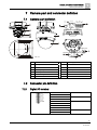
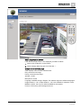
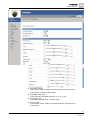
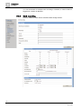
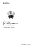
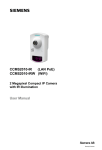
CFMS2015
1/3'' IP Fix Dome Camera, 2 MP,
D/N
Configuration
A6V10334028
20.12.2011
Building Technologies
1
Copyright
1 Copyright
Data and design subject to change without notice. Supply subject to availability.
© 2011 Copyright by Siemens AG
We reserve all rights in this document and in the subject thereof. By acceptance of
the document the recipient acknowledges these rights and undertakes not to
publish the document nor the subject thereof in full or in part, nor to make them
available to any third party without our prior express written authorization, nor to
use it for any purpose other than for which it was provided.
Edition: 20.12.2011
Document ID: A6V10334028
2
Siemens AG
A6V10334028
20.12.2011
Table of Contents
1
Copyright ............................................................................................................2
2
About this document .........................................................................................5
2.1
Content of document ............................................................................................5
2.2
Meaning of symbols .............................................................................................5
2.3
Contact .................................................................................................................6
2.4
Target group.........................................................................................................6
3
Safety...................................................................................................................7
3.1
General safety percautions ..................................................................................7
3.2
Transport ..............................................................................................................7
3.3
Installation ............................................................................................................7
3.4
Maintenance.........................................................................................................7
3.5
Sensor characteristics ..........................................................................................7
4
EU-directives ......................................................................................................9
5
Technical data ..................................................................................................10
6
Details for ordering ..........................................................................................12
6.1
Package contents...............................................................................................12
7
Camera part and connector defintion ............................................................13
7.1
Camera part defintion.........................................................................................13
7.2
Connector pin definition......................................................................................13
7.2.1
Digital I/O terminal ..............................................................................13
7.2.2
Power terminal ....................................................................................14
7.2.3
Video out connector ............................................................................14
7.2.4
Default/Reset buttons .........................................................................14
7.2.5
SD card ...............................................................................................14
8
Installing the camera........................................................................................15
8.1
Precautions ........................................................................................................15
8.1.1
SD memory card .................................................................................15
8.1.2
Power supply ......................................................................................15
8.2
Concept of the network camera .........................................................................16
8.3
Setting network camera environment.................................................................16
8.4
Connecting the camera and personal computer via network.............................16
8.5
Using the camera search application "Webcam IP Manager" ...........................18
8.6
Login dialog ........................................................................................................20
8.7
Viewing and listening..........................................................................................21
8.8
Resolution ..........................................................................................................24
9
Configuration....................................................................................................25
9.1
Compression ......................................................................................................25
9.2
Network settings.................................................................................................28
9.2.1
Basic ...................................................................................................29
9.2.2
DDNS Settings....................................................................................30
9.2.3
FTP Server..........................................................................................31
3
Siemens AG
A6V10334028
20.12.2011
9.3
9.4
9.5
9.2.4
RTSP...................................................................................................31
9.2.5
HTTPS ................................................................................................32
9.2.6
IEEE802.1X.........................................................................................32
9.2.7
3GPP...................................................................................................33
Image parameter ................................................................................................34
9.3.1
Basic camera settings.........................................................................34
9.3.2
Camera mask zone settings ...............................................................37
9.3.3
Camera cropping settings ...................................................................38
9.3.4
Camera OSD settings .........................................................................40
Alarm ..................................................................................................................40
9.4.1
Alarm...................................................................................................40
9.4.2
Audio event upload .............................................................................43
9.4.3
Alarm server........................................................................................43
Recording ...........................................................................................................44
9.5.1
FTP Recording ....................................................................................44
9.5.2
SD recording .......................................................................................47
9.5.3
Email recording ...................................................................................49
9.5.4
NAS recording.....................................................................................52
9.6
Audio ..................................................................................................................54
9.7
Date / Time .........................................................................................................55
9.8
Access protection ...............................................................................................56
9.9
9.10
9.8.1
Administrator .......................................................................................56
9.8.2
User list ...............................................................................................56
Firewall ...............................................................................................................57
9.9.1
IP Address filter...................................................................................57
9.9.2
Forbidden ports ...................................................................................57
9.9.3
Forbidden protocols ............................................................................58
System................................................................................................................59
9.10.1
Settings ...............................................................................................59
9.10.2
Update.................................................................................................59
9.10.3
Configuration.......................................................................................60
9.10.4
Temperature........................................................................................61
9.10.5
Test .....................................................................................................61
9.11
Log......................................................................................................................62
9.12
Notice .................................................................................................................63
10
Utility program application..............................................................................64
10.1
NAS player setup................................................................................................64
10.2
Audio recording setup.........................................................................................64
10.3
Firmware update setup.......................................................................................64
11
Maintenance......................................................................................................66
12
Disposal.............................................................................................................67
Index
68
4
Siemens AG
A6V10334028
20.12.2011
About this document
Content of document
2
2 About this document
2.1
Content of document
This document contains information on the configuration of the product.
2.2
Meaning of symbols
Orientation guide
[-> 3]
Cross-reference
Save
Button
<Ctrl>
Key
Tips and information
5
Siemens AG
A6V10334028
20.12.2011
2
About this document
Contact
2.3
Contact
Contact information
If you have questions or suggestions regarding the product or this documentation,
please contact our Technical Competence Center.
Intranet: http://
Email
Phone/Fax/Mobile
International
[email protected]
Tel.: +49 89 9221 8000
Fax: +49 89 6367 2000
Germany,
Switzerland,
Austria
[email protected]
Tel.: +49 89 9221 8000
Fax: +49 89 6367 2000
France
[email protected]
Tel.: +33 89 9708 324
United Kingdom
[email protected]
Tel.: +44 12 9143 7920
Sweden
[email protected]
Tel.: +46 8 6290 300
Norway
Tel.: +47 22 6336 25
Tel.: +47 22 6321 70
Mobile: +47 9826 7140
Mobile: +47 9287 3010
Denmark
Tel.: +45 46 33 82 14
Finland
Tel.: +35 85 0361 3909
Siemens AG provides training courses for all products.
2.4
Commissioning personnel
Target group
z
z
z
Operating personnel
z
Configure the product at the
z
place of installation according to
customer-specific requirements. z
Check the product operability
and release the product for use
by the operator.
Searches for and corrects
malfunctions.
Performs the procedures for
proper operation of the
product.
z
z
Has obtained suitable specialist training for the
function and for the products.
Has attended the training courses for
commissioning personnel.
No particular qualification required.
Has received instruction from the operational
startup personnel.
6
Siemens AG
A6V10334028
20.12.2011
Safety
General safety percautions
3
3 Safety
3.1
General safety percautions
z
Read the general safety precautions before installing/configuring/operating the
device.
z
Follow all warnings and instructions marked on the device.
z
Keep this document for reference purposes.
z
This document must always accompany the product.
Liability claim
z
3.2
3.3
Use only spare parts and accessories that have been approved by the
manufacturer.
Transport
z
Keep the packaging material for future transportation.
z
Do not expose the device to mechanical vibrations or shocks.
Installation
z
It is recommended that all preparatory work (e.g. fitting of accessories) be
carried out in a workshop prior to final installation.
z
The environmental conditions recommended by the manufacturer must be
observed. See section 'technical data'.
z
Do not operate the device close to sources of powerful electromagnetic
radiation.
z
The device should only be used for indoor applications.
z
The mounting surface must be solid and non-combustible.
Danger of electrical shock/fire hazard/damage to the device due to
incorrect connection
z
3.4
3.5
Connect the device only to a power source that complies with SELV
requirements and with the Limited Power Source requirements to EN 60950-1.
Maintenance
z
Do not attempt to service or modify this device yourself. Refer this work to
qualified service personnel.
z
Do not use liquid cleaners or sprays that contain alcohol, spirit or ammonia.
Sensor characteristics
The following conditions may be observed when using a CMOS camera. These are
inherent in the design and do not stem from any fault in the camera itself.
7
Siemens AG
A6V10334028
20.12.2011
3
Safety
Sensor characteristics
z
Vertical smear:
This phenomenon occurs when viewing a very bright object.
z
Patterned noise:
This is a fixed pattern, which may appear over the entire monitor screen when
the camera is operated at a high temperature or in a low luminance
environment.
z
Jagged picture:
When viewing stripes, straight lines, or similar patterns, the image on the
screen may appear jagged.
8
Siemens AG
A6V10334028
20.12.2011
EU-directives
4
4 EU-directives
This product complies with the requirements of the following European directives.
The EU declaration of conformity is available to the responsible agencies at:
Siemens AG
Industry Sector
Building Technologies
76181 Karlsruhe
Germany
European Directive 2004/108/EC „Electromagnetic Compatibility”
Compliance with the European Directive 2004/108/EC has been proven by testing
according to the following standards:
Emitted interference:
EN 61000-6-3
Interference resistance:
EN 50130-4
9
Siemens AG
A6V10334028
20.12.2011
5
Technical data
5 Technical data
Model
CFMS2025
Type
2 Megapixel, Day/Night IP Fix Dome
Image sensor
1/3” 1080p HD CMOS image sensor OV2715
Effective pixels
1920 (H) X 1080 (V)
Image compression method
H.264 / MPEG4 / MJPEG (Triple streaming)
Image frame rate
H.264 1080p @12 fps
720P, SXGA, VGA 25 fps
Service monitor
CVBS @ 25 fps for PAL
Electrical
Synchronisation
Internal
Signal/noise ratio
> 50 db
Lens type
Varifocal 3 mm (W) - 9mm (T)
Horizontal viewing angle
93.0 - 31.7°
IR cut filter
Yes
Sensitivity
Colour: 0.5 lux (F1.2) 50 IRE
B/W: 0.3 lux (F1.2) 50 IRE
White balance
ATW/Manual
Electric shutter
AES 1/25-1/10000 sec
Back-light compensation (BLC)
6 zones
Automatic gain control (AGC)
Yes
Audio codec
G.711
Audio feature
Two-way mono audio; full duplex
Alarm
Yes; 3x Alarm In & 1x Alarm Out
Motion detection
Yes; 1 MD window & 3 sensitivity levels
Privacy zone
8
Image enhancement
2 DNR
Power supply
Power requirement
DC 12 V / AC 24 / PoE
Power consumption
5.5 W
Power connector
Terminal block
Environment
Enfironmental operating temperature
0 – 50ºC
Operating humidity
0 – 80% RH
Storage temperature
-20 to +60ºC
Network
Web broswer
IE 6.0 above/ Firefox, Safari with VLC plug-in
(VLC version 0.9.6 or above)
Security
Firewall / forbidden protocol / 802.1x
Ethernet
1 x 10/100 base-T Ethernet connection for LAN
Internet protocol
TCP/IP, UDP, HTTP, HTTPs, SMTP, SNMP,
DNS, DHCP, NTP, ARP, ICMP, FTPc, FTPs,
DDNS, RTSP (RTP, RTCP), IGMP v3, UpnP,
CIFS, NFS, IEC802.1x, ONVIF
10
Siemens AG
A6V10334028
20.12.2011
Technical data
5
Network
Connections
RJ-45 for Ethernet 10BaseT/100BaseTX (PoE)
Power connector (terminal block type)
Terminal block for 3 alarm inputs, 1 output
I/O Connector
Network port
RJ45 with LED’s
Audio IN/OUT
Spring type
Video output
2-pin connector
Mechanical
Protection rating
NA
Resistance to shock
NA
Dimensions (DxH)
126 mm x 115 mm
Weight
480 g
11
Siemens AG
A6V10334028
20.12.2011
6
Details for ordering
Package contents
6 Details for ordering
Type
Order No.
Designation
CFMS2025
S54561-C93-A5
1/3'' IP Fix Dome, 2 MP, Day / Night
Further products and accessories can be found in the internet:
www.siemens.com/securityproducts
6.1
Package contents
z
IP camera
z
Video cable
z
2 anchors
z
2 screws
z
Template
z
2 GB SD card (in box)
z
Installation instruction
z
Utilities CD (including software and documentation)
12
Siemens AG
A6V10334028
20.12.2011
Camera part and connector defintion
Camera part defintion
7
7 Camera part and connector defintion
Au. IN
GND
Au. OUT
GND
Al. IN 3
Al. IN 2
Al. IN 1
GND
COM
Al. OUT
Camera part defintion
Ethernet
DC12V
AC24V
+ -~ ~
Ethernet
DEFAULT
RESET
VIDEO OUT
126.0
87.0
105.7
Logo
PC
DC12V
AC24V
+ -~ ~
Au. IN
GND
Aú. OUT
GND
Al. IN 3
Al. IN 2
Al. IN 1
GND
COM
Al. OUT
7.1
VIDEO OUT
5 x 10
SD CARD
RESET
DEFAULT
Unit: mm
7.2
7.2.1
SD CARD
1
Camera base
8
Power supply port
2
Adjusting mechanism
9
Ethernet connector
3
Lens
10
I/O terminal
4
Focal length ring
11
Video output
5
Focus ring
12
Reset button
6
Camera housing
13
SD card
7
Dome cover
14
Default button
Connector pin definition
Digital I/O terminal
Au. IN
GND
Au. OUT
GND
Al. IN 3
Al. IN 2
Al. IN 1
GND
Al. COM
Al. OUT
Au.IN
Audio in
GND
Au.OUT
Audio out
GND
AI.IN3
Alarm in
AI.IN2
AI.IN1
GND
AI.COM
Alarm out
AI.OUT
13
Siemens AG
A6V10334028
20.12.2011
7
Camera part and connector defintion
Connector pin definition
7.2.2
Power terminal
White: Power Black: Power +
7.2.3
Video out connector
Video Signal Output
7.2.4
Composite video output
Default/Reset buttons
DEFAULT
7.2.5
DC 12 V / AC 24 V power
terminal
RESET
DEFAULT
Return to factory default by
pressing button (after 5 Sec)
RESET
System restart
SD CARD
To record images when alarm
events happen.
SD card
SD CARD
14
Siemens AG
A6V10334028
20.12.2011
Installing the camera
Precautions
8
8 Installing the camera
8.1
8.1.1
Precautions
SD memory card
NOTICE
Please install the SD memory card before switching on the camera.
The system cannot detect an SD card that is inserted during operation.
8.1.2
z
The camera supports SD and SDHC cards.
z
Physical interface: Part 1. Physical Layer Specification; Version 1.01.
z
Images may not be recorded or read correctly if an unsupported SD card is
used with the camera.
z
A SD card can be used for loop recording of images. The life-span (number of
re-writes possible) of a SD card depends on its capacity. For loop recording, it
is rec-ommended to use a large-capacity SD card.
z
Do not use a card containing the data recorded by another device with the
camera as this may result in the camera not functioning correctly.
z
Do not modify or overwrite the data, or change the folder name of a SD card.
This may result in the camera not functioning correctly.
z
Data recorded with the camera does not comply with the image file format Exif
and the DCF standard. If the SD card is to be removed to play images, use a
personal com-puter for this purpose. Other devices may not be capable of
displaying the images.
z
Use only new SD cards that were delivered by the manufacturer.
Power supply
Be sure to use only a suitable power adapter. Using the wrong type of power
adapter may cause the camera to malfunction, heat up, or catch fire. Before using
the power adapter, carefully read and observe the Work safety information and the
notes below.
z
Do not allow the connectors on the power adapter to come into contact with
any other metal objects as this may result in short-circuit.
z
To connect the power adapter, firmly insert the plug end of the cable into the
power terminal. Do not insert the plug into other jacks as this may cause
malfunctioning.
z
When removing the connection cable, disconnect it by pulling the plug. Do not
pull on the cable.
z
Do not drop the power adapter or subject it to strong impact.
z
Do not use the power adapter in hot and humid places.
z
Temperature increase on the surface of the adapter is normal. Before moving
the adapter to another location, unplug it from the wall outlet, and wait until its
temperature decreases.
z
Buzzing noises may come from inside. This does not indicate malfunction.
z
Using the power adapter near a radio, TV, or cell phone may cause
interference. Use the adapter at sufficient distances from these devices.
15
Siemens AG
A6V10334028
20.12.2011
8
Installing the camera
Concept of the network camera
8.2
Concept of the network camera
The network camera can deliver video images and audio in real time using the
Internet or an intranet. The camera is equipped with Ethernet (RJ-45) 10BASET/100BASE-TX network interfaces.
It can be used in various indoor environments.
Ethernet
Switch
8.3
PC
Setting network camera environment
Items needed for network camera monitoring system
z
Administrator's personal computer
The personal computer that is given all authorities for setting, operating,
monitoring and other functions with the network cameras is called the
"administrator's personal computer" in this manual.
z
PC requirements
–
Windows Vista or XP as OS
–
Internet Explorer Version 6.0 (or higher) or Safari or Mozilla FireFox
–
CPU: Intel Pentium 4,2 GHz or higher
–
Memory: 1 GB or more
z
Network camera
Please purchase the appropriate number of cameras required for your
application.
z
Connection equipment such as a hub and router suiting the network system
environment, as well as a LAN cable ( Cat 5e cable is recommended).
z
Camera search application "Webcam IP-Finder"
Install this application from the CD-ROM supplied as an accessory.
1. Double-click "ipfinder_Setup.exe" in the CD-ROM
2. install the application following the instructions on the screen
8.4
Connecting the camera and personal computer via
network
IP address
To connect to the network, the administrator needs to set the network camera IP
address.
There are two options to set the IP address.
z
Entering an IP address manually (factory default)
16
Siemens AG
A6V10334028
20.12.2011
Installing the camera
Connecting the camera and personal computer via network
z
8
Obtaining an IP address automatically from the DHCP server
Entering the IP address manually.
Your camera is set to this mode at the factory with IP address 192.168.0.10, so you
need to enter this IP address manually to access the camera for the first time.
Obtaining an IP address automatically from the DHCP server
If your network uses a DHCP server, you do not need to change the IP address of
the camera. To activate this function, the option DHCP must be selected in the
"Network/Basic Settings".
The IP address of the network camera can be changed from time to time when
the DHCP server is used. For this reason, it may not be possible to connect a
network camera due to an IP address change if the network camera is accessed
using the previously set IP address.
To enable accessing the network camera in this case, a fixed IP address needs to
be assigned manually to the network camera. Make sure to read the instruction
manuals for the network equipment, as well as the manuals for the router, hub
and modem.
To manually select the basic network settings, "Manual" must be selected and the
IP address, subnet mask, default gateway, primary DNS and secondary DNS
have to be entered.
Connection configuration
There are two configuration options for connecting network cameras:
z
Crossover connection
z
Connection via a hub, switch, or router
You do not need to assign an IP address to a hub.
The default IP address of your camera is 192.168.0.10. Set the IP address of your
personal computer in the same subnet. (The network segment must be the same
segment when directly connecting using a cross-over cable or connecting via the
hub). When connecting more than one camera, connect the cameras one by one
and assign an unused IP address to each one.
You can also use the LAN port of your broadband router. However, when using
the broadband router while the DHCP server function is enabled, turn on the
power after connecting the camera to the router. The camera gets the IP address
from the router's DHCP server. The IP address will not be 192.168.0.10.
For more information, refer to the user documentation for your computer.
Connecting camera and personal computer
1. Connecting the LAN cable
Connect the LAN cable (straight cable) to the camera and to the hub.
Alternatively, connect the camera to a personal computer using the LAN cable
(cross-over cable).
2. Turning Power on
Connect AC 24 V to the power terminal.
Setting the IP address of the personal computer.
z
Use a free IP address (other than 192.168.0.10, which is the camera's IP
address).
z
For example., set the IP address to 192.168.0.20 (and the subnet mask to
255.255.255.0).
17
Siemens AG
A6V10334028
20.12.2011
8
Installing the camera
Using the camera search application "Webcam IP Manager"
z
For details on the procedure, refer to the user guide for the personal computer.
Testing the camera connection using ping.
z
Start a command prompt. Type "ping 192.168.0.10" and press "Enter".
D If the "Reply from..." message appears, the connection is correctly established.
Search for the camera using the "Webcam IP Manager" and view a camera image.
See Section 6.5.
1. Start "Webcam IP Manager" and click "Search".
2. Check whether the camera name "nwcam05" is displayed in the camera list.
3. Click "nwcam05" to select the camera.
D The camera name, IP address and HTTP port number are displayed in the
"Network Camera Lists" field.
4. Double-click the camera you wish to log in to in the camera list.
D The screen for entering the user name and password will appear.
5. Enter the administrator log-in ID and password. See "Login dialog".
D A camera image screen of the network camera will appear.
To view images without using "Webcam IP Manager," launch the Internet
browser, enter URL http://192.168.0.10/ in the address box and press "ENTER."
It takes about 10 seconds to activate the camera.
If a port number other than "80" is set, enter the port number after ":" as in
http://192.168.0.10:88.
8.5
Using the camera search application "Webcam IP
Manager"
The "Webcam IP Manager" is an application for searching for network cameras
that can currently be viewed from the administrator's personal computer or a user's
personal computer.
Setting up "Webcam IP Manager"
1. Insert the CD in the CD-ROM drive of the personal computer.
2. Double-click the "ipfinder_Setup" file in the CD-ROM and install "Webcam IP
Manager" in accordance with the instructions on the screen.
IMPORTANT
"Webcam IP Manager " is compatible only with Windows Vista and Windows XP.
Glitches may occur on your personal computer if it is run with another operating
system. Do not install "Webcam IP Manager " with other operating systems.
Using "Webcam IP Manager " to search for a camera
Set the personal computer to “Administrator authorization“ when using “Webcam
IP Manager”.
1. Select "Start" > "Programs" > "Webcam IP-Finder".
18
Siemens AG
A6V10334028
20.12.2011
Installing the camera
Using the camera search application "Webcam IP Manager"
8
2. Start "Webcam IP Manager" and click "Search".
D All the cameras currently connected to the network will be displayed. To
exit the program, click "Exit".
3. Select the camera you want to log in to in the list of cameras and double-click
it.
D The selected camera name and IP address are displayed in the network
camera login fields.
4. Log in to the selected camera as an administrator. (See "Login dialog")
To exit without logging in, click "Exit".
SSDP (Simple Service Discovery Protocol / network protocol)
Z
Prerequisite:
The Web-Cam IP Manager and all devices are located in the same network
segment. If a device and the Web-Cam IP Manager are not located in the same
network segment, you must ensure that the associated gateway (router)
passes the SSDP multicast messages sent by the Web-Cam IP Manager on to
the network segment where the device is located.
1. Start the Web-Cam IP Manager by loading IP Manager.exe. This application is
found on the CD included with delivery.
D The Web-Cam IP Manager program window will open:
19
Siemens AG
A6V10334028
20.12.2011
8
Installing the camera
Login dialog
2. Click "Start".
D The Web-Cam IP Manager program window will now display a list of all the
devices available for communication along with their IP and MAC
addresses. Each device's IP address or MAC address is unique.
3. Select the camera whose home page you want to access.
4. Click "Home page of selected device".
D The home page of the selected camera will appear. See Section 6.8
Components of the unit home page.
8.6
Login dialog
The content of the following chapters is based on the assumption that Microsoft
Internet Explorer IE 6.0 or higher has been installed.
A person who has logged in as an administrator can perform all functions.
Administrator login
1. Search for the camera using the "Webcam IP-Finder", double-click the camera
you wish to log in to.
D The login dialog will appear.
20
Siemens AG
A6V10334028
20.12.2011
Installing the camera
Viewing and listening
8
2. Enter the administrator login ID and password in the "Name" and "Password"
fields, respectively and click "Login".
The administrator login ID and password are "admin" and "admin" by default.
D The camera image screen will appear.
IMPORTANT
The administrator login allows rewriting of all settings. Make sure to change the
de-fault administrator login ID and password to ensure camera security. Keep the
new administrator login ID and password handy for future use. Information on
how to change the administrator login ID and password can be found in Section
"Access protection”.
8.7
Viewing and listening
Images of the network camera can be viewed using the Internet browser of your
personal computer.
Z Preparations before displaying
Enable cookies
Set "Browser setting when proxy server is used".
Change "Security" in the Internet options as follows.
1. Click “Tools” on Toolbar
2. Click "Internet Options"
3. Select the "Security" tab.
4. Click on "Intranet" if the camera to be operated is inside the intranet, click on
"Internet" if the camera is on the Internet.
5. Click "Level customize."
6. Activate the following radio buttons in the list displayed:
-
"Enable" for "ActiveX control and plug in execute"
-
"Enable" for "Execution of script of ActiveX control marked safe even when
script is executed"
-
"Enable" for "Download of signed ActiveX control "
7. Click "OK."
8. Login to the camera.
D Your browser will be launched and the camera login screen will appear.
See Section "Login dialog" for the login method.
When the security warning screen (VeriSign) appears on the first use of the
system, click "Yes."
Administrator authorization is needed to install "Active-X control." Install "Active-X
control" after changing the personal computer setting to "Administrator
authorization."
Browser settings when proxy server is used
If a proxy server is used, setting the browser to bypass the proxy server during
communication with the network camera is recommended.
21
Siemens AG
A6V10334028
20.12.2011
8
Installing the camera
Viewing and listening
1. Launch the browser.
2. Click “Tools” on Toolbar
3. Select "Internet options".
4. Select the "Connect" tab.
5. Click "LAN Setting."
D The screen for setting a local area network (LAN) will appear.
Z If the checkbox “Will use a proxy server” is not marked:
z
The browser is not set to use a proxy server. Click "Cancel" and quit setting.
Z If the checkbox “Will use a proxy server” is marked:
1. Click "Detail setting."
D A proxy setup screen will appear.
2. Enter the IP addresses of the network cameras in the fields marked "Do not
use the proxy server with addresses started with the following”.
3. Click "OK."
When Windows XP SP2 is used: Click "Install" for "Active-X control."
All browsers except the IE can only be used for image viewing and compression
setting.
A proxy server protected by a firewall sometimes cannot be connected to the
network camera. Consult the network administrator to avoid impacts on network
camera operations.
Communication with the network cameras via a proxy server may cause problems. Install the network cameras after consulting with the network administrator.
If the network cameras are used in conjunction with a proxy server, it may take
some time for the images to be displayed after a login, or the frame rate of the delivered images may be reduced.
All browsers except the IE only support image viewing and compression setting.
22
Siemens AG
A6V10334028
20.12.2011
Installing the camera
Viewing and listening
8
When using Windows XP SP2
If the camera image screen is not displayed, proceed as follows.
1. Select "Pop-up Blocker" on the toolbar.
2. Select "Always Allow Pop-ups from This Site...".
Components of unit home page
OSD: displays camera name, date and time.
Play: shows the live image
Pause: pauses the live image
Speaker: On/Off
Microphone: On/Off
Language: standard setting is English. The website supports 5 different languages.
Image streams 1, 2 & 3: Triple streams 1, 2 & 3 are available for selection. H.264,
MPEG4 & JPEG , but only one JPEG available for the streams.
E-zoom: PTZ control, preset setings and more.
23
Siemens AG
A6V10334028
20.12.2011
8
Installing the camera
Resolution
8.8
Resolution
There are different kinds of resolution depending on the function selected for the
network camera.
Item
No.
Limitation
Resolution
1
If you choose VGA for stream 1, you have to choose between SVGA , VGA
and QVGA for the other streams. The resolution of the streams should be in
the same group.
2
Cropping
E-zoom
OSD &
Mask zone
Group 1 (VGA)
SVGA
VGA
QVGA
Group 2 (D1)
D1
CIF
2CIF
Group 3 (1080p)
1080p
Group 4 (SXGA)
SXGA
VGA
QVGA
Group 5 (720p)
720p
D1
4CIF
The resolution of stream 3 follows stream 1 or stream 2
1
Cropping and E-zoom are mutually exclusive.
2
Cropping stream source is based on the largest resolution of normal
streams.
3
Total stream count with cropping is limited. Ex: If resolution is in group 1,
total maximum number of normal and cropping stream is 8.
Group 1 (VGA) (except
SVGA)
8
Group 2 (D1)
6
1
Cropping and E-zoom are mutually exclusive.
2
Only resolution in group 1 (except SVGA) and normal stream number less
than 2 (including number 2) can own E-zoom feature.
1
Regular features of normal streams
24
Siemens AG
A6V10334028
20.12.2011
Configuration
Compression
9
9 Configuration
9.1
Compression
Image mode
z
3 streams can be selected. Stream 1, stream 2 and stream 3 can be set to
H.264, JPEG and MPEG4. No codec can be selected twice.
z
All resolutions H.264, JPEG and MPEG4 are possible.
25
Siemens AG
A6V10334028
20.12.2011
9
Configuration
Compression
z
Quality Value: When variable bit rate is selected as the rate control mode and
customized mode in Compression Ratio, the quality value can be selected
between 1 and 31.
–
Low: default is 31
–
Mid-low: default is 24
–
Standard: default is 16
–
Mid-high: default is 9
–
High: default is 1
H.264- The following settings are enabled when "Image Mode" is set to H.264
z
Resolution
Configure the resolution. The higher the resolution the larger the image file.
Possible settings: SVGA, VGA, QVGA (when PC/VGA Resolution is selected)
D1, 2CIF, CIF, QCIF, 4CIF (when Video Resolution is selected).
z
Frame rate: 7 frame rates can be selected (1, 2, 3, 5, 10, 12, 25)
z
Rate control mode: you can choose between variable bit rate and constant bit
rate.
z
Compression Ratio
Set the quality of the delivered images. The size of the image files (H.264 files)
depends on the compression ratio.
–
z
z
–
Mid-low: 24
–
Standard: 16
–
Mid-high: 9
–
High: This setting produces lowest image quality. The file size decreases.
Quality value is set to 1.
Compression Ratio
Set the quality of the delivered images. The size of the image files (H.264 files)
depends on the compression ratio.
–
Low compression: This setting produces the highest image quality. The file
size increases.
–
Mid compression: Standard setting.
–
High compression: This setting produces the lowest image quality. The file
size decreases. Only aktiv at “variable bitrate”.
Quality Value: When variable bit rate is selected as the rate control mode and
customized mode in Compression Ratio, the quality value can be selected
between 1 and 31.
–
z
z
Quality value default: 31
When picture resolution is ≥ 720p, the file size could be more than 4 MB.
GOP: default is 25 (1 I frame plus 24 P frames). GOP can be selected between
1 and 64.
–
25fps:GOP 1~64
–
12fps: GOP 1~36
–
10fps: GOP 1~30
–
5fps: GOP 1~15
–
3fps: GOP 1~9
–
2fps: GOP 1~6
–
1fps: GOP 1~3
Profile: You can choose between Baseline, Main profile and High profile.
JPEG - The following settings are enabled when "Image Mode" is set to "JPEG".
26
Siemens AG
A6V10334028
20.12.2011
Configuration
Compression
9
z
Resolution
Configure the resolution. The higher the resolution the larger the image file.
Possible settings:SVGA, VGA, QVGA (when PC/VGA Resolution is selected)
D1, 2CIF, 4 CIF, CIF, QCIF (when Video Resolution is selected)
z
Frame Rate: 7 frame rates can be selected (1, 2, 3, 5, 10, 12, 25)
z
Compression Ratio
Set the quality of the delivered images. The size of the image files (JPEG files)
depends on the compression ratio.
z
z
–
Low: This setting produces highest image quality. The file size increases.
Quality value is set to 90.
–
Mid-low: 70
–
Standard: 50
–
Mid-high: 30
–
High: This setting produces lowest image quality. The file size decreases.
Quality value is set to 10.
–
Customized mode: Ratio, Quality value can be adjusted between 3 and 90.
Compression ratio
Set the quality of the delivered images. The size of the image files (JPEG files)
depends on the compression ratio.
–
Low compression: This setting produces the highest image quality. The file
size increases.
–
Mid compression: Standard setting.
–
High compression: This setting produces the lowest image quality. The file
size decreases.
Quality Value: when Customized mode is selected in Compression Ratio, the
quality value can be selected between 3 and 90.
–
Low: default is 31
–
Mid-low: default is 24
–
Standard: default is 16
–
Mid-high: default is 9
–
High: default is 1
MPEG4 - The following settings are enabled when "Image Mode " is set to
"MPEG4".
z
Resolution
Configure then resolution. The higher the resolution the larger the image file.
Possible settings:SVGA, VGA, QVGA (if PC/VGA Resolution is selected)
D1, 2CIF, 4CIF, CIF, QCIF (if Video Resolution is selected)
z
Frame Rate: 7 frame rates can be selected (1, 2, 3, 5, 10, 12, 25)
z
Rate control mode: You can choose between variable bit rate and constant bit
rate.
z
Compression Ratio
Set the quality of the delivered images. The size of the image files (JPEG files)
depends on the compression ratio.
–
Low: This setting produces highest image quality. The file size increases.
Quality value is set to 31.
–
Mid-low: 24
–
Standard: 16
–
Mid-high: 9
–
High: This setting produces lowest image quality. The file size decreases.
Quality value is set to 1.
27
Siemens AG
A6V10334028
20.12.2011
9
Configuration
Network settings
z
z
Compression ratio
Set the quality of the delivered images. The size of the image files (JPEG files)
depends on the compression ratio.
–
Low compression: This setting produces the highest image quality. The file
size increases.
–
Mid compression: Standard setting.
–
High compression: This setting produces the lowest image quality. The file
size decreases.
Quality Value: When variable bit rate is selected as the rate control mode and
customized mode in Compression Ratio, the quality value can be selected
between 1 and 31.
–
Low: default is 31
–
Mid-low: default is 24
–
Standard: default is 16
–
Mid-high: default is 9
–
High: default is 1
z
Bit Rate: 6 modes including 256 kb, 512 kb, 1M, 2M, 3M, 4M.
z
GOP: default is 25 (1 I frame plus 24 P frames). GOP can be selected between
1 and 64.
–
25fps:GOP 1~64
–
12fps: GOP 1~36
–
10fps: GOP 1~30
–
5fps: GOP 1~15
–
3fps: GOP 1~9
–
2fps: GOP 1~6
–
1fps: GOP 1~3
Cropping 1-5
The frame rate value for each cropping can be set between 1 and 5 fps.
9.2
Network settings
You can configure your basic camera settings, DDNS, FTP server, RTSP, HTTPS,
IEEE802.1X, SNMP & 3GPP by selecting "network setting" in the "Configuration"
menu.
28
Siemens AG
A6V10334028
20.12.2011
Configuration
Network settings
9.2.1
9
Basic
BASIC
Camera Name: Enter the name of your camera here. The default name is
“nwcam05”.
Camera Name Enable: Select "ON" to enable this function or "OFF" to disable it.
NETWORK
Mode:
z
DHCP: The IP address is obtained automatically;
z
PPPoE: The IP address is obtained automatically;
z
Manual: Enter the IP address as shown in the screenshot above.
IP Address: If you have selected the option "Manual", enter your IP address here.
Subnet Mask: Please use default number: 255.255.255.0
Default Gateway: Leave blank. It is not necessary to enter a Default Gateway if it is
not used. Ask your Network Administrator for information on the default gateway.
Primary DNS: (same as above)
Secondary DNS: (same as above)
29
Siemens AG
A6V10334028
20.12.2011
9
Configuration
Network settings
Ipv6 address configuration
Ipv6: Select "ON" to use the new internet protocol or "OFF" to disable it.
Port
Stream 1 to Stream 3, cropping 1-5:
We recommend using the default settings. In case these need to be changed,
contact your system administrator.
UPnP Use:
When “ON” is selected, the camera can be detected automatically by the PC. It is
not necessary to have the Web cam IP manager installed.
Bonjour Use
When “ON” is selected, the camera can be detected automatically by the Internet
Explorer browser. It is not necessary to have the Web cam IP manager installed.
AUDIO output
When “ON” is selected, a voice message indicating camera’s IP address can be
delivered to a headphone.
9.2.2
DDNS Settings
Z This function is available when you have registered with a DDNS provider.
Select "ON" to enable the DDNS function.
1. Select your DDNS server from the list box, enter your user ID and password
and confirm your password.
2. Click "Save" to save your settings.
30
Siemens AG
A6V10334028
20.12.2011
Configuration
Network settings
9.2.3
9
FTP Server
1. Select "ON" to activate the FTP function. Enter your login ID and password and
confirm your password.
2. Select the number of maximum connections from the "Max Simultaneous
Connections" list box. Click “Save” to save your settings.
This function is used to download directories/files to or to delete them from the SD
memory card.
9.2.4
RTSP
Authentication: Select "ON" to enable the RTSP function. Enter your login ID and
password and confirm your password.
Multicast Address: The default address is 231.0.0.222.
31
Siemens AG
A6V10334028
20.12.2011
9
Configuration
Network settings
Stream1-3: Select the transfer type and enter the RTSP port, video port and audio
port.
Cropping 1-5: Select the transfer type and enter the RTSP port, video port and
audio port.
9.2.5
HTTPS
Here you can upload a certificate. Click “Browse”. A window will pop up. Select the
file you want to upload. Click upload to upload the file.
9.2.6
IEEE802.1X
Certificate:
1. Click” Browse”
D A window will open.
2. Select the desired certificate
3. Click “Upload” to upload the certificate..
32
Siemens AG
A6V10334028
20.12.2011
Configuration
Network settings
9
Setting:
z
EAPOL version: Select 1 or 2.
z
EAP identity: Enter the EAP identity.
z
Private key password: Enter your private key password.
z
Enable IEEE 802.1X: Select "ON" to enable it or "OFF" to disable it.
Select "ON" to enable SNMP V1, SNMP V2C and SNMP V3, respectively, or select
"OFF" to disable them.
9.2.7
3GPP
3GPP is the third generation technical standard which refers to GSM core network
as the basis and UTRA as the wireless interface.
33
Siemens AG
A6V10334028
20.12.2011
9
Configuration
Image parameter
9.3
9.3.1
Image parameter
Basic camera settings
Here you can configure the basic settings of the camera such as image size and
quality.
1. Select "Image Parameters" in the "Configuration" menu.
–
A sub menu for camera function setting will appear.
2. Select "Basic" in the sub menu.
–
The "Camera - Basic Settings" dialog will appear.
3. Configure the individual settings.
–
Click "Save" to save your settings.
The settings will not be applied unless "Save" is clicked.
34
Siemens AG
A6V10334028
20.12.2011
Configuration
Image parameter
z
9
Day-Night Settings:
Select “Auto”, “Day” or “Night” mode according to the environment.
Only active if not linked to alarm input.
z
Day-Night Delay Time:
Choose the day-night delay time from 0, 5, 10, 15, 30.
z
Day-Night Level:
Choose the day/night level: Low, Mid, High.
z
Preset image:
Choose OFF, Indoor, Outdoor, Tunnel and Casino, according to the
environment.
35
Siemens AG
A6V10334028
20.12.2011
9
Configuration
Image parameter
z
Automatic Exposure:
Controls the light intensity of the image. 2 types of specific application
conditions can be selected: Manual or AES (Automatic Electronic Shutter) by
the camera depending on your application environment. When use the Manual,
the Shutter speed is enabled to adjust
z
Brightness:
Adjust the brightness between 0 and 255.
z
Contrast:
Set the contrast level between 0 and 255.
z
Saturation:
Adjust the saturation between 0 and 255.
z
Shutter Speed:
Set the desired shutter speed between 1/25 and 1/10000 s. The shutter speed
can be set to 1/25, 1/50, 1/100, 1/120, 1/150, 1/200, 1/300, 1/500, 1/750,
1/1500, 1/5000 and 1/10000 s. The network camera will adjust the aperture to
the ambient light level.
z
Manual Gain:
Adjust the manual gain level between 0 and 24 dB. This function is available for
manual lenses only.
z
AWB:
Set the white balance values to meet the environment condition for best color
rendition.
“ON”: the color of camera is automatically adjusted according to external
lighting condition.
“OFF”: Adjustable by user manually, this is useful for some specific condition
which AWB may be unaffordable to perform correctly. You can set the current
R/B color temperature manually.
z
R Gain, GR Gain, GB Gain, B Gain, D Gain:
Adjust manual gain value of R Gain, B Gain between 0 and 255. This function
is available for manual lenses only.
z
Noise Reduction:
Select either “ON” or “OFF”.
z
Sharpness:
Increasing the sharpness value enhances the edges and small features in your
camera images. You can adjust the sharpness between 0 and 255. .
z
Backlight Compensation:
Set this option to “ON” or to “OFF”
z
Picture Flip:
When mounted upside down select “ON” to activate the flip function. With this
function you can flip an image upside down. Select "ON" to activate or "OFF" to
deactivate the flip function.
z
Picture Mirror:
The selected image will be side-inverted. Select "ON" to activate or "OFF" to
deactivate the mirror function.
36
Siemens AG
A6V10334028
20.12.2011
Configuration
Image parameter
9.3.2
9
Camera mask zone settings
z
Choose the desired color for the masks.
37
Siemens AG
A6V10334028
20.12.2011
9
Configuration
Image parameter
z
Select “ON”, then click “Set Mask Zone” to start mask setting.
z
Drag a mask rectangle on the screen. Click “OK” to complete the selection.
z
Click “Save” to enable the mask setting.
Up to 8 masks can be set on the screen.
9.3.3
z
EZOOM is not supported when cropping function is on.
z
Privacy zone is not supported when cropping function is on.
z
The cropping size of width and height must be multiple of 32. Ex: 320*160.
z
The smallest cropping size will be 128*128.
z
At least a resolution that should be set in VGA or D1.
Camera cropping settings
38
Siemens AG
A6V10334028
20.12.2011
Configuration
Image parameter
9
1. Mark the appropriate "Enable" checkbox and enter a name, then click “Set
Cropping Area” to start cropping setting.
2. A cropping setting screen will pop up as shown. Select one of the cropping
options (QVGA, CIF, QCIF, Free Size) at the bottom of the screen. A red-mesh
rectangle will appear on the screen.
3. Select one of the predefined sizes.
D The zone appears at the screen.
4. Move the zone by clicking the left mouse button in the center of the target
position.
D The red mesh will jump to that position.
5. Click “OK” to save and finish the settings.
6. Click “Save” to save your settings.
Select free size
1. Click on one corner of the window and drag it to the desired size
2. Click “OK” to save and finish the settings.
39
Siemens AG
A6V10334028
20.12.2011
9
Configuration
Alarm
NOTICE
Max. 5 cropping areas can be set on the screen.
E-zoom is not supported when cropping function is on.
Privacy zone is not supported when cropping function is on.
The cropping size (width and height) must be a multiple of 32. Example: 320*160.
The smallest cropping size will be 128*128.
The minimum resolution should be set to VGA or D1.
9.3.4
Camera OSD settings
This function setups the text position and colour of camera name, Alarm text or
DATE/TIME on the screen. Of course, the corresponding ENABLE flag for each
item shall be ”ON” to activate this function, such as camera name Enable in
Network setup, Text enable in Alarm setting and Display in DATE/TIME setting.
9.4
9.4.1
Alarm
Alarm
If a sensor or another device is connected to the alarm input, an alarm will be
triggered when an event is detected by the sensor or the other device. For
example, if a sensor is attached to a door, an alarm will be triggered each time the
door is opened. An enabled motion sensor will trigger an alarm a change on a
screen is detected.
On the rear panel, there are 3 digital alarm inputs (AL1, AL2, AL3). Before using
the alarm function, you need to define some parameters.
40
Siemens AG
A6V10334028
20.12.2011
Configuration
Alarm
9
External digital input 1
1. Alarm Input
When “ON” is selected: external alarm will be detected.
The following functions will be enabled when the option “Alarm Input” is
selected.
B/W mode: The camera is switched to monochrome mode when a trigger
signal is received.
2. Input Type
Normally Open (NO): open if nothing occurs but closed in case of an alarm.
Normally Closed (NC): closed if nothing occurs but open in case of an alarm.
3. Text Enable
When "ON" is selected, an alarm message will be displayed on the screen.
4. Text
Enter a text for the alarm message.
Max. 22 characters can be entered.
5. Audio Output
When "ON" is selected, an audio alarm message will be sent to an external
speaker.
A speaker with integrated amplifier inside has to be connected to the AUDIO out
jack.
6. Event
Select an event.
Pre-recorded voice files with the extension .wav that have been uploaded to
the SD memory card can be selected as alarm messages. Up to 10 audio
sources can be selected.
7. Actions
Default is OFF, preset can be selected 1~16.
41
Siemens AG
A6V10334028
20.12.2011
9
Configuration
Alarm
The settings are similar to those for alarm inputs, with some additional functions:
z
Motion Detection
–
Select "ON" to enable the motion detection function.
–
Select “Track”, to track the moving object.
–
Default setting: “OFF”
External digital inputs 2, 3
External digital inputs 2, 3: All configurations are the same as those made for
external digital input 1, except that input mode B/W is not available.
Motion detection settings
The settings are similar to those for alarm inputs, with some additional functions:
1. Motion Detection
Select "ON" to enable the motion detection function.
Default setting: “OFF”.
2. Area
Click “Set Motion Area”.
An image screen will pop up.
Select the target area by dragging the mouse.
3. Sensitivity
Select the desired sensitivity.
High: Even small changes in brightness or motion are detected.
Mid: Intermediate between High and Low.
Low: Only large changes in brightness or motion are detected.
4. Event
Select an event.
Pre-recorded voice files with the extension .wav that have been uploaded to
the SD memory card can be selected as alarm messages. Up to 10 audio
sources can be selected .
Alarm output
1. Alarm mode:
The alarm output can be activated when any of the following events occurs:
–
B/W: when the image changes to monochrome.
–
Event: When alarm input 1, alarm input 2 or alarm input 3 or motion is
triggered, the alarm output will reflect this immediately as well.
2. Output hold time:
Set a time to hold the alarm output. You can select 0, 5, 10, 15, or 30 seconds.
This function is used when a siren, buzzer or emergency light is connected.
42
Siemens AG
A6V10334028
20.12.2011
Configuration
Alarm
9.4.2
9
Audio event upload
Select an audio event. Upload the *.wav file as a voice alarm message to the SD
card or a PC. Up to 10 audio events can be selected. Alarm input 1 and motion
setting will show different effects depending on which audio event you selected.
9.4.3
Alarm server
Configure the alarm server as follows:
1. Conditions:
Select either "Alarm" or "Motion".
2. Alarm Server IP Address:
Enter the IP address of the alarm server.
3. Alarm Server Port Number:
Enter the alarm server port number.
4. Alarm Input Message:
Enter a message text. This text must not be longer than 64 characters. When
an alarm event occurs, the alarm server will receive this message text.
5. Motion Alarm Message:
Enter a message text. This text must not be longer than 64 characters. When a
motion event occurs, the alarm server will receive this message text.
43
Siemens AG
A6V10334028
20.12.2011
9
Configuration
Recording
9.5
9.5.1
Recording
FTP Recording
44
Siemens AG
A6V10334028
20.12.2011
Configuration
Recording
9
You can save image files via FTP. Set the FTP recording conditions first. Choose
between FTP server 1 and 2.
z
FTP Recording Conditions
You can save your image files generated by scheduled recording, alarm
recording, or motion-triggered recording.
z
Scheduled Recording
Select the recording condition in the recording schedule table for all days from
Monday to Sunday: Stop, All Day, Schedule 1 or Schedule 2.
z
Recording by Alarm
45
Siemens AG
A6V10334028
20.12.2011
9
Configuration
Recording
Z Prerequisite: The alarm inputs have been configured.
Then proceed as follows:
1. Record Source
Select either JPEG or MPEG4 format
2. Pre-Recording Frame
Select the number of images to be recorded before an alarm occurs. Images of
the moment when the alarm occurs are not included.
D With JPEG format, 0, 1, 3, 5, or 10 frames can be selected.
Not required with MPEG4 format.
3. Pre-Recording Cycle
Set a time interval for pre-alarm recording. With JPEG format, 1, 2, 5, 10, 30s
can be selected.
D Not required with MPEG4 format.
4. Recording Frame
Select the number of images to be recorded immediately after an alarm has
occurred. Images of the moment when an alarm occurs are not included.
D With JPEG format, 1, 2, 5, 10, 30, or 60 frames can be selected.
Not required with MPEG4 format.
5. Recording Cycle
Set a time interval for alarm recording. With JPEG format, 1, 2, 5, 10,
30,60,90,120s can be selected.
D Not required with MPEG4 format.
6. Recording Time
When MPEG4 is selected, the recording time can be set to 2, 5, or 10s.
z
Recording by Motion
Z Prerequisite: Motion detection has been configured.
z
All other settings are the same as for recording by alarm (see above).
FTP Server Settings - Server 1 and 2
Enter the FTP server name, Login ID, Password, FTP port number, FTP mode, and
FTP connecting method.
z
FTP Server Name: Enter a server name or address.
z
Login ID: Only for users who are authorized to access the server.
z
Password: Enter the registered password associated with the login ID.
z
Password (Confirm): Re-enter the password
z
FTP Port Number: Set “21” as default
z
FTP Mode: PORT - This mode is for most FTP applications; PASV - This mode
is used when the camera is operated in a network environment that is behind a
firewall.
z
FTP Connecting Method: Reconnect - The network camera logs in/out for each
file transfer; Continuous Connection - The network camera is always
connected.
Connecting method
You can choose to save your image files to either FTP server 1 or FTP server 2, or
automatically switch between servers.
46
Siemens AG
A6V10334028
20.12.2011
Configuration
Recording
9
SD card backup in case of FTP failure
You can make a SD card backup even in case of an FTP failure.
The network camera automatically stores images on the SD card if they cannot be
stored on the server due to a network failure, or other error condition. The stored
images can be manually transferred to the FTP server when the problem has been
resolved.
Function ON/OFF: Select "ON" to activate the SD card backup in case of FTP
failure.
Accumulation Cycle: Set a time interval in seconds (1, 2, 5, 10, 15, 30, 60 or 120
seconds) for recorded images to be stored.
Overwrite: When set to "ON", the images stored on the SD card will be overwritten
when the capacity of the SD card has been reached, starting with the oldest files.
9.5.2
SD recording
47
Siemens AG
A6V10334028
20.12.2011
9
Configuration
Recording
Images captured according to a schedule, during alarm situations (motion, network
cable removed, etc.), can be stored on a SD memory card that is inserted in the
network camera.
Configure the individual settings.
z
Recording by Alarm
Z Prerequisite: The alarm inputs have been configured.
Then proceed as follows:
1. Record Source
Select either JPEG or MPEG4 format
2. Pre-Recording Frame
Select the number of images to be recorded before an alarm occurs. Images of
the moment when an alarm occurs are not included.
0,1,3,5,10 frames can be selected if JPEG format selected. No need for
MPEG4 format.
3. Pre-recording cycle
Set a time interval for pre-alarm recording 1, 2, 5, 10, 30s can be selected for
JPEG format, no need for MPEG4 format
4. Record frame
Set the number of images to be recorded immediately after an alarm occurs.
Images of the moment when an alarm occurs are not included.
1,2,5,10,30,60 frames can be selected if JPEG format selected. No need for
MPEG4 format.
5. Recording cycle
Set a time interval for alarm recording 1, 2, 5, 10, 30,60,90,120s can be
selected for JPEG format, no need for MPEG4 format
6. Recording time
If MPEG4 selected, please set the recording from 2,5,10s.
z
Recording by Motion
Z Prerequisite: Motion detection has been configured.
z
All other settings are the same as for recording by alarm (see above).
48
Siemens AG
A6V10334028
20.12.2011
Configuration
Recording
9
z
Scheduled Recording
z
Select the recording condition in the recording schedule table for all days from
Monday to Sunday: STOP, All Day, Schedule 1 or Schedule 2.
z
Recording by Network loss
1. Select network recording. During a network loss, the network camera
automatically stores images to the SD card based on your settings.
2. Recording Cycle
Set a time interval for network recording: 1, 2, 5, 10, 30, 60, 90 or 120 s
z
Overwrite
ON: Data stored on the SD card will be overwritten when the capacity of the SD
card has been reached, starting with the oldest file.
OFF: Recording will be stopped if the capacity of the SD memory card is reached
during recording.
z
Click "Save".
D The changes will be saved.
When the overwrite mode is set to “ON”, files will be deleted starting with the
oldest files. If important data needs to be saved, set the overwrite mode to “OFF”.
9.5.3
Email recording
You can receive images if you have set up your email account.
49
Siemens AG
A6V10334028
20.12.2011
9
Configuration
Recording
Set the conditions for sending email according to a schedule
Z If "Schedule" is selected
1. Subject – Enter a subject title for the email to be sent.
50
Siemens AG
A6V10334028
20.12.2011
Configuration
Recording
9
2. Message – Enter a text for the alarm message.
3. Attach Image – When "ON" is selected, you can attach image files to your
email.
4. Recording Schedule – Select the days to be included in the recording schedule.
5. Recording Cycle - Set a time interval for scheduled recording: 30, 60, 120, 240,
600, 1200, 1800 or 3600 s.
Set the conditions for sending email in the event of an alarm
Z If "Alarm" is selected:
1. Subject – Enter a subject title for the email to be sent
2. Message – Enter a text for the alarm message.
3. Attach Image – When "ON" is selected, you can attach image files to your
email.
Set the conditions for sending email when a motion is detected
Z If "Motion" is selected:
1. Subject – Enter a subject title for the email to be sent
2. Message – Enter a text for the alarm message.
3. Attach Image – When "ON" is selected, you can attach image files to your
email.
Authentication settings
No Authentication - no restrictions
SMTP - Simple Mail Transfer Protocol (SMTP) is an Internet standard for electronic
mail (email) transmission across Internet Protocol (IP) networks
PLAIN - PLAIN is a registered SASL authentication mechanism, which is supplied
as a parameter to the AUTH command. The PLAIN authentication mechanism is
described in RFC 2595. PLAIN is the least secure of all the SASL authentication
mechanisms, since the password is essentially sent unencrypted across the
network.
LOGIN - The LOGIN mechanism is supported by Microsoft's Outlook Express, as
well as by some other clients.
CRAM-MD5 - In CRAM-MD5 authentication, the server first sends a challenge
string to the client. The client responds with a user name followed by a space
character and then a 16-byte digest in hexadecimal notation. The digest is the
output of HMAC-MD5 with the user's password as the secret key, and the server's
original challenge as the message. The server also calculates its own digest with
its notion of the user's password. If the client's digest and the server's digest match
then authentication was successful.
1. Email Server (SMTP) - Enter your outgoing mail server (SMTP).
D For further information contact your admin.
2. Email User ID – Enter your email account ID.
3. Password – Enter your email account's password.
4. Password (Confirm) – Confirm your email password.
5. Administrator email Address – Enter your email address.
6. Click "Save & Test Email” to save and test your email settings.
Mail to address list
51
Siemens AG
A6V10334028
20.12.2011
9
Configuration
Recording
You can send emails to multiple users according to schedule, or when an alarm is
triggered or a motion is detected.
9.5.4
NAS recording
This is a method to store data on network-based storage devices.
52
Siemens AG
A6V10334028
20.12.2011
Configuration
Recording
9
1. Choose the recording condition:
Select the desired recording condition (Schedule, Alarm or Motion) to trigger
the recording session.
If Schedule mode is selected, the data will be stored on the NAS in JPEG
format only.
D After the “Recording Schedule” condition has been selected, the
corresponding detailed recording field appears.
2. Select the conditions you need.
3. Select the desired NAS mode: NFS or CIFS
NFS is for network storage devices using UNIX systems while CIFS is for
Windows systems.
4. Enter the storage device’s address, user ID, password, and the data path
where the data is to be stored in the Server, User ID, Password and Path text
fields, respectively.
5. Click “Save” to complete the NAS setup procedure.
Make sure all NAS devices are available in network before activating this function.
53
Siemens AG
A6V10334028
20.12.2011
9
Configuration
Audio
9.6
Audio
You can configure your audio settings by enabling the audio input and output.
z
Format
Two audio compression formats are supported: A-law and U-law.
z
Audio input
Audio Input: Select "ON" for receiving audio from a microphone connected to
the camera.
Audio Input Level:
z
–
HIGH - Increases the audio input level.
–
MIDDLE - Adjusts the audio input level to a medium level.
–
LOW - Reduces the audio input level.
Audio output
Audio Output: Select "ON" for delivering audio to a headphone or an active
speaker connected to the camera.
Audio Output Level:
–
HIGH - Increases the audio output level.
–
MIDDLE - Adjusts the audio output level to a medium level.
–
LOW - Reduces the audio output level.
54
Siemens AG
A6V10334028
20.12.2011
Configuration
Date / Time
9.7
9
Date / Time
z
Display
Select “ON” to display the date/time on the screen. The position and color are
set via the camera's on-screen menu.
z
Synchronization Mode
z
–
Manual:
Enter the date and time.
–
NTP: For details contact your system admin.
You can also enable Network Time Protocol (NTP) via the NTP server.
Enter a host name for the NTP server, select a time adjustment period, and
click “Save and Test” to start testing the NTP function.
–
Synchronization from PC:
The system date/time can be synchronized via the PC settings.
Daylight
Select "ON" to activate the daylight-saving function if you are in a daylightsaving time zone (effective for NTP mode only).
55
Siemens AG
A6V10334028
20.12.2011
9
Configuration
Access protection
9.8
9.8.1
9.8.2
Access protection
Administrator
z
Administrator functions
Select “Administrator Functions” in the setting menu. You can set up the
system password, user language and logoff time.
z
Password
The default settings for system admin ID and password are as follows:
Admin ID: admin
Password: admin
You can create your own Admin ID and password in these fields
Language: English
You can select from 5 languages
User list
Besides the administrator, general users can access the camera once they have
been assigned a user ID and password by the system administrator.
You can add users by assigning them individual IDs and passwords in the "User
Settings" field and adding them to the user list.
User level:
56
Siemens AG
A6V10334028
20.12.2011
Configuration
Firewall
9.9
9.9.1
9
z
Advanced users can see the live picture and perform basic functions (e.g. PTZ
control, etc.).
z
Users can only view the live image; they have no authorization to perform any
functions.
Firewall
IP Address filter
1.
Enter the IP address(es) to be processed by the firewall system in the IP
address field(s). Up to 10 addresses can be set.
2. Enable the IP address(es) in the list which are to pass the firewall filter by
selecting "ON".
3. Select either "Allowed" or "Denied" or "OFF".
9.9.2
z
Allowed: The listed IP addresses will pass the firewall.
z
Denied: The listed IP addresses will be rejected by the firewall.
Forbidden ports
All the listed ports that enabled (set to "ON") will be rejected by the firewall.
57
Siemens AG
A6V10334028
20.12.2011
9
Configuration
Firewall
9.9.3
Forbidden protocols
CMP or UDP protocols can be rejected by the firewall if assigned.
58
Siemens AG
A6V10334028
20.12.2011
Configuration
System
9.10
System
9.10.1
Settings
9
CGI-Lock is a system security setting that is used to activate or deactivate the login
data for the CGI-commands. If you select "ON", you always have to enter an ID
and password for the web page. You can change everything using the cgicommands. If "OFF" is selected, you will have no access.
9.10.2
Update
You can update the system firmware once the update file is available. It is the
customer's responsibility to update the firmware. All camera motions will be shut
down during the firmware update. Close all dialogs and screens before starting a
firmware update. Never disconnect the power cable and the LAN cable during the
firmware update process. Rebooting the camera after a firmware update may take
approx. 15 minutes. After you finish a software update, please reboot you computer
at first.
z
Do not disconnect power during a SW update.
Otherwise, it causes SW update failure and you have to send back your
camera to Siemens maintenance.
59
Siemens AG
A6V10334028
20.12.2011
9
Configuration
System
9.10.3
Configuration
Camera configuration information can be exported and saved to a personal
computer. It can also be imported from the personal computer to network cameras.
z
Import - Click on “Import” and select the configuration settings file to be
imported to your network camera.
z
Export - Click on “Export” and select the directory to to save the file on your
computer.
z
Factory Default - Clicking on "Default" in the setup.
Basic IP camera network settings (e.g. IP address and camera name) will not be
reset when a software reset is made. Also the export configuration settings and
the settings for import and factory default.
60
Siemens AG
A6V10334028
20.12.2011
Configuration
System
z
9.10.4
9
Network Camera Reboot - When you click on "Reboot" the following message
will pop up: "This will reboot the camera. Are you sure?". Click "OK" to reboot
the network camera.
Temperature
There are options for displaying the temperature: Celsius and Fahrenheit. The
current internal temperature of the camera is displayed. If the temperature exceeds
the limit value, an e-mail will be sent depending on the temperature notification
interval setting. If “0” is selected, the e-mail will be delivered only once.
When the temperature of the camera is too high, for example above 70°C,a
warning message will pop up.
9.10.5
Test
The status of the system can be displayed here.
61
Siemens AG
A6V10334028
20.12.2011
9
Configuration
Log
9.11
Log
Event log
z
Select the menu sequence Settings > Log.
By clicking the buttons “Display All Logs”, “Display System Logs”, “Display User
Logs”, "Delete logs" the corresponding logs will be displayed and can be
processed.
62
Siemens AG
A6V10334028
20.12.2011
Configuration
Notice
9.12
9
Notice
63
Siemens AG
A6V10334028
20.12.2011
10
Utility program application
NAS player setup
10 Utility program application
10.1
NAS player setup
The application for playing back NAS files can be found on the DVD that is
included in the delivery.
Z Prerequisite: NAS recording has been configured.
1. Click on the green cross button and select the path of the NAS file to be played
back.
2. Click "Play"
3. Click "Stop"
10.2
Audio recording setup
This application is found on the DVD that is included in the delivery. You can
record a new voice file and upload it to the network camera. This application can
generate alarm out events. After you finish audio record, please control alarm
audio setting.
To record audio, proceed in the following manner:
Z Prerequisite: Audio recording has been configured.
1. Click on the green cross button and select the path to which to save the *.wav
file.
2. Make sure a microphone is installed before you start recording your voice.
3. Click on the red button and start recording your voice.
4. Click "Stop".
10.3
Firmware update setup
This application is found on the DVD that is included in the delivery. You can
update multiple network cameras simultaneously.
To update firmware, proceed in the following manner:
64
Siemens AG
A6V10334028
20.12.2011
Utility program application
Firmware update setup
10
Z Prerequisite: The firmware update software has been installed .
1. Select the software version from the "Filter" drop-down list.
2. Select the network camera you want to update. The upgrade tool supports the
simultaneous firmware update of up to 100 network cameras.
3. Click on "Browse…" and select the software version for the network camera.
4. Click on "Upload" to start the firmware update.
Current FW version : X.2.2.984
65
Siemens AG
A6V10334028
20.12.2011
11
Maintenance
11 Maintenance
z
The camera is maintenance-free.
z
There is a limitation of rewrites that is possible with the SD memory card.
Replacing the SD memory card when performing periodic maintenance on the
camera is recommended, at latest after 10,000 writing cycles.
z
Small amounts of dirt or dust can be cleaned from the camera using a clean
soft cloth. Do not touch the lens area.
z
If the surface is touched accidently use a soft cloth moistened with alcohol to
clean it.
z
Defective modules should be sent to the nearest Siemens office to be
forwarded to the service centre.
66
Siemens AG
A6V10334028
20.12.2011
Disposal
12
12 Disposal
All electrical and electronic products should be disposed of
separately from the municipal waste stream via designated
collection facilities appointed by the government or the local
authorities.
This crossed-out wheeled bin symbol on the product means the
product is covered by the European Directive 2002/96/EC.
The correct disposal and separate collection of your old appliance
will help prevent potential negative consequences for the
environment and human health. It is a precondition for reuse and
recycling of used electrical and electronic equipment. For more
detailed information about disposal of your old appliance, please
contact your city office, waste disposal service or the shop where
you purchased the product.
67
Siemens AG
A6V10334028
20.12.2011
Index
Index
A
Administrator, 20, 56
Alarm output, 42
FTP recording, 45
FTP server, 31, 46
G
Audio, 30
GOP, 26
Audio recording setup, 64
H
Authentication, 31
Automatic Exposure, 36
H264, 26
AWB, 36
I
B
Image mode, 25
Bit rate, 28
Bonjour use, 30
Brightness, 36
C
Import, 60
Intenet options, 21
Internet browser, 21, 21
IP address, 22
IP address filter, 57
Camera name, 29
Ipv6 address configuration, 30
Cleaning, 7
J
Compression Ratio, 26
Contrast, 36
Cropping, 28
Cropping settings, 39
D
Daylight, 55
JPEG, 26
L
Login dialog, 20
M
Manual Gain, 36
Day-Night Delay, 35
Motion detection, 42
Day-Night Level, 35
MPEG4, 27
Day-Night settings, 35
Multicast, 31
DDNS settings, 30
Default gateway, 17
DHCP, 29
N
NAS player setup, 64
DHCP server, 17
Noise Reduction, 36
Display, 55
O
E
Overwrite, 49
Email server, 51
P
Export, 60
F
Factory default, 60
Firewall, 57
Firmware update setup, 64
Password, 56, 56
Picture flip, 36
Picture mirror, 36
Power supply, 15
Preset image, 35
Forbidden ports, 57
Primary DNS, 29
Forbidden protocol, 58
R
Frame rate, 26
R Gain, B Gain, 36
68
Siemens AG
A6V10334028
20.12.2011
Index
Reboot, 61
Resolution, 26
RTSP port number, 32
S
Saturation, 36
SD recording, 48
Secundary DNS, 29
Sensor characteristics, 7
Sharpness, 36
Shutter speed, 36
Subnet mask, 29
Synchronization mode, 55
T
Temperature, 61
Transfer type, 32
U
Unit home page, 23
UPnP use, 30
User, 56
W
Webcam IP Manager, 18
69
Siemens AG
A6V10334028
20.12.2011
Issued by
Siemens AG
Infrastructure & Cities Sector
Siemensallee 84
D-76187 Karlsruhe
www.buildingtechnologies.siemens.com
Document ID
A6V10334028
Edition
20.12.2011
© 2011 Copyright Siemens AG
Technical specifications and availability subject to change without notice.