1
DAIKIN OIL HYDRAULIC EQUIPMENT
Safety precautions
! Before using products, please read “Safety precautions for the oil hydraulic equipment and systems”
carefully and use those properly.
! Above caution items are divided into three categories shown below. All the cautions listed below are
important to ensure safety, and must be followed entirely.
DANGER
: Items that may cause imminent and dangerous situationleading to a
death or a serious injury when not followed as instructed.
WARNING
: Items that may lead to serious accident such as a death and an injury
when not followed as instructed.
CAUTION
: Items that may lead to an injury and/or property damage when not
followed as instructed.
Be sure to follow these cautions any time, because these are the important
cautions to use the products safely and to avoid a serious accident or a fatal
accident.
*
*
These “Danger” “Warning” and “Caution” don't cover all things. When you meet to handle the products, read the
manual securely and understand it completely, then start to handle the products or systems.
Be sure to comply with the law or regulation shown below, for the sake of safety use of the products.
" High pressure gas control law
" The OSHA
" The fire service Act
! Caution for working oil
" Improper working oil may cause a malfunction or a trouble.
[
[
[
[
Caution ]
Caution ]
Caution ]
Caution ]
[
[
[
Caution ]
Caution ]
Caution ]
[
Caution ]
[
Caution ]
[
Danger ]
Use the designated oil only.
Prohibit mixing a different kind working oil or mixing the working oil with lubricant.
Use the working oil in a proper range of viscosity indicated in the specifications.
Maintain the contamination level of the working oil cleanliness within a range in specification. A machine may get
trouble and be damaged if the machine will be used continuously in a condition that the working oil is
contaminated.
Working oil deteriorates as being used. Working oil should be replaced in a certain interval.
Supply oil into the unit from an oil supply port not so as to mix up with foreign substance or moisture.
The extreme descend of oil level may cause a trouble or malfunction. Maintain the oil level within a range between
the max. and the min..
Clean the oil attached on your skin away by a soap or so. If oil sticks on a skin, according to a circumstance, a
rough skin may happen. So, be care full not to spread oil out onto somebody.
There will be a fear of getting burnt in case of high oil temperature. Exchange of oil after the oil temperature will
descend.
As many working oil has hazard of catching fire, prohibit welding and using fire around systems and machines. It
may cause a trouble of fire.
i
Caution in use of oil hydraulic machines and systems
! Cautions in use of a pump/motor
" Before using a pump/motor, please read the operation manual carefully and use the product properly.
Use a product the model is properly chosen
[
[
Caution ] Oil hydraulic equipment has many similar products of which appearance is the same or resembles. Make sure if
the pump/motor are the goods which are properly chosen by checking up the name plate or the carved seal when
you need to install the pump/motor.
Danger ] Don't use a product in the atmosphere explosive or dangerous to fire except the product to be sited for the
atmosphere.
Handling products
[
[
[
[
Caution ] When you handle a pump/motor, you will be sometimes injured. Wear protectors depending on the situation.
Caution ] As there are many cases that pump and motor are heavy products, it may cause to catch one's finger in the
products or hurt one's waist according to working posture. So, take care for the working procedure sufficiently.
Caution ] Don't put a external force on the products such as riding on a product, hammering it or dropping it. These may
cause malfunction, destruction and oil leak.
Caution ] Wipe out entirely the oil stuck on the products or floor. It may cause someone to drop products or lead to slip and
be wounded.
Setting, removal, wiring and piping of pump/motor
[
[
[
[
Caution ] Keep clean for a base or set hole of pump/motor. Insufficient tightening of bolts and seal break may cause
destruction and oil leak.
Caution ] When pump/motor are installed, use regular bolts and tighten these with regulated torque. If a irregular method is
applied, it may cause malfunction, destruction and/or oil leak.
Caution ] Specialists should do the works of mounting, dismantling, and piping of pump and motor.
Caution ] The works of pump/motor's mounting, dismantling, piping and wiring should be carried out after the power supply
is cut off and confirm that motor or engine etc. stops securely. Besides, relies the pressure and confirm pressure
is not left in the oil circuit.
Wiring and combining rotational part
[
[
[
Warning ] Wiring should be done by just qualified persons.
Warning ] Wiring should be done after power is cut off, otherwise it is likely that electric shock will happen.
Warning ] The combined part of pump/motor should have a secure fixing method not so as to be out of place or scatter. Be
sure to provide a protection cover in order to prevent winding up of hands or clothes into the pump/motor.
Installation of pump/motor
[
[
[
[
[
Caution ] Have enough rigidity for a base on which pump/motor are mounted.
Caution ] Don't give the shafts of pump/motor a shock by a hammer. It may cause a destruction of product.
Caution ] Confirm if the whirling amplitude and surface amplitude are within the permissible range.
Caution ] Install a pump after confirming the revolution direction of a pump and a motor or an engine to match to each other
through an arrow mark on a name plate or a carved seal.
Caution ] When a pump/motor requires drain piping, make the drain piping so that the internal pressure doesn't exceed the
level regulated. Besides, even if pump/motor stops for a long time, make the drain piping so that working oil in the
casing doesn't drop.
Max. pressure regulation
[
Warning ] When a pump except ones with pressure compensation function (with max. pressure adjustment) is used, be sure
to install a relief valve, regulating the max. pressure on the oil hydraulic circuit, near by the discharge side of the
pump.
ii
In case to operate a pump/motor
[
[
[
[
[
[
[
[
[
[
[
[
[
[
Warning ] Before starting operation of a system which mounts a pomp/motor, confirm if the oil circuit and wiring are properly
done and do not have any part loosen. Check up especially on the combination or connection between a
electrical control circuit and a solenoid valve. Turn on electricity to each solenoid operated valve and verify that
each solenoid works as indicated.
Warning ] System starting must be conducted under the conditions the pressure setting of a pressure control device
including a relief valve descends, and confirm the pressure surely descends through a pressure gauge. After
confirming that this operation condition is properly proceeding, start a normal operation and check up the
operation pressure keeps a normal one.
Warning ] Don't operate a pump/motor as the cover of rotation part is removed.
Warning ] Prohibit touching a rotation part as paying attention to clothes or ornaments not so as to be wound up into the
rotation part.
Warning ] Check up by means of an ammeter if excess load is not onto the unit. Operate the unit after solving a problem of a
malfunction as a improper installation or seizure can be considered for the cause in case of excess load.
Caution ] In several cases, such as starting a pump/motor with a oiling port on the casing for the first time, checking and
amending an oil circuit, or stopping for a long time, supply clean working oil to fill the casing.
Caution ] Repeat an inching operation till a pump surely absorbs oil. Nevertheless it doesn't absorb oil, then do the work of
air purging from the piping (through an air bleed valve or so). As soon as foam or working oil is purged out from
the air purging plug, or pump operating sound changes, close the air purging plug and keep operation about five
minutes without load as it is.
Caution ] Make a motor start in low load condition and make sure the revolution is chosen to the correct direction.
Caution ] Operate a pump within the suction pressure range indicated.
Caution ] Make sure the drain line's pressure of a pump/motor is within the permissible range.
Caution ] In case that the operation sound of a pump is louder than normal one, cavitation possibly happens. Accordingly
check up the tank oil level, clogging of a suction strainer or a filter or loosen suction piping. Make sure especially
that surge pressure arising at ON/OFF or at the procedure of speed transfer is within the permissible range. (If the
operation sound is different from the normal one, malfunction or failure may take place. It is important for you to
find abnormality urgently as you remember the normal operation sound.
Caution ] Operate a pump/motor properly in accordance with the specifications including pressure, flow rate, revolution
speed, kind of oil, oil temperature, and viscosity, which are listed on the operation manual, catalogue, drawing
and specification table.
Caution ] Don't touch a casing of a pump/motor directly by hand, because the casing sometimes leads to high temperature.
Caution ] Stop operation and take necessary measures as soon as abnormal phenomena on a pump/motor, such as
abnormal noise, abnormal heat emission, abnormal vibration, oil leak, arising smoke or abnormal smell, happens.
It is recommended to attach a sensor detecting such abnormalities. Otherwise, it will lead to damage, fire and
injury.
Management of working oil (working fluid)
[
[
Caution ] Operate in a circuit structure so that the contamination level of the working oil can be always kept within the
manufacture's recommended value and check up periodically a filter and a contaminated level. Moreover,
periodically inspect the characteristics of oxidation, deterioration and moisture contents of the working oil, and
replace the working oil when those characteristics exceed the value the manufacture recommends.
Caution ] When working oil used is changed, do it after sufficient flushing, while avoiding mixture with different kinds of oil.
Treatment of maintenance
[
Warning ] Prohibit remodeling, disassembling and reassembling. Otherwise, It can not exhibit the performance expected
and leads to a cause of a failure or an accident.
Treatment of maintenance/custody
[
[
[
Caution ] Contact the manufacturer in case that it is unavoidable to do remodeling, disassembling and reassembling.
Caution ] Maintain a dust-proofing and a rust-proofing characteristics while paying attention to the environment conditions
such as ambient temperature and humidity, when a pump/motor is transferred and preserved.
Caution ] The replacement of the kinds of seal sometimes is required in case that a pump/motor is used after a long time
custody.
iii
! Caution in use of oil hydraulic valve
" Before using a pump/motor, please read the operation manual carefully and use the product properly.
Overall valves
[
[
[
[
[
[
Warning ] Use it within the max. working pressure regulated.
Caution ] Use it in the range regulated of flow rate, temperature, working oil and viscosity.
Warning ] Tighten set bolts of a valve or piping screws with the torque regulated.
Warning ] Connect properly a connection port of valve with indicated piping or so.
Caution ] Maintain working oil in the contamination level recommended.
Caution ] Don't operate a valve manually and quickly.
Solenoid valve
[
[
[
[
[
[
[
[
[
[
Warning ] Prohibit using a valve out of the permissible supply voltage.
Caution ] Don't use a valve at more than the max. switching frequency.
Danger ] Prohibit using a valve in the atmosphere explosive or easy to fire except the products coping with the atmosphere.
Caution ] Use the product to match the environment, if the product is used under the environment necessary for water
proof.
Warning ] Prohibit wiring under conditions that electricity keeps turning on or valve and hydraulic circuit are pressurized.
Caution ] Don't touch a surface of solenoid directly by hand, because the solenoid sometimes leads to high temperature.
Caution ] Use wires of the kinds and diameter which suit the product.
Caution ] Have a proper ground wiring to the terminal where the grounding is indicated.
Caution ] Don't supply power to twin-solenoid at the same time.
Caution ] In case of AC solenoid valve (except a valve with a rectifier), seizure (or snapping of a wire) of solenoid coil may
happen when malfunction such that a foreign subject is blocked in a spool or so takes place. Solenoid coil itself is
molded with fire-proofing plastics and there will not be dangerous to fire normally, but if the mold has been
deteriorated in long time use, risk of catching fire can be expected. The use of DC type solenoid operated valve
is recommended, wishing safer condition, under the circumstance that there are many combustible things around
the site easy to catch fire.
Installation and removal
[
[
[
[
[
[
[
[
[
[
[
[
[
Caution ] Don't remove a cap (protective plug) on a valve port just before using (installation or piping) it. Pay attention so
that dust or so will not enter the inside of the valve during piping work or installation work.
Caution ] Put covers on the valve port, valve setting face and pipes removed not so as to invade foreign subjects into the
valve when the valve is removed. Don't remove these covers before the reassemble.
Caution ] Make sure the kind and cleanliness of the oil before supplying working oil.
Caution ] Concerning a valve with manual handling mechanism, make sure if it can be properly switched by hand or
confirm the manual settings, before starting long term operation or restarting after no use for a long time.
Caution ] Tighten rock nuts of the valve that the setting has been completed. If a cap or a cover is attached, set it on the
port.
Caution ] Don't use a valve for a foot step. Otherwise, it may cause a damage to a valve.
Caution ] External force should not be loaded onto a valve like striking or dropping valve.
Caution ] Treat wires and connectors gently not so as to load unnatural force.
Caution ] Pay attention to pressure remained in a oil circuit when the removal of pipes and valves is needed. Remove those
after making sure that the pressure is entirely purged. If the pressure remains, it may lead to injury by splashing
oil. If you touch high pressure oil and the oil invades into your skin, see a doctor immediately.
Caution ] Do an overhaul of a valve in accordance with the handling manual of the manufacturer. Some valves are
prohibited overhauling. In that case, never overhaul the valve.
Caution ] Use new parts for a gasket or a O ring when installing or reassembling a valve.
Caution ] Do the work of checking, adjusting and overhauling after oil, dust or moisture stuck around a valve or a connector
has been cleaned away not so as to invade foreign subjects into a valve or a connector.
Caution ] Be sure to supply oil up to the regulated level and do the several works such as air purging in the oil circuit,
checking up oil leak and seasoning operation, when the unit starts to operate for the first time after the
installation, or after checking, adjusting, amending, or after no use for a long time.
iv
! Caution in use of oil-con
" Before using a oil-con, please read the operation manual carefully and use the product properly.
General cautions
[
[
[
[
[
Warning ] Be sure to follow the several cautions stated in this chapter and comply with the laws and regulation mentioned
below.
1. The OSHA 2. The Fire Service Act 3. JIS B 8361 hydraulic system general regulation
Caution ] When you handle a product, you will be sometimes injured. Wear protectors depending on the situation.
Caution ] The site work may cause to catch one's finger in the products or hurt one's waist according to the working posture
or the product's weight. So, take care for the working procedure sufficiently.
Caution ] Wipe out entirely the oil stuck on the products or floor. It may cause someone to lead to slip and be wounded.
Caution ] Specialists should do the works of transportation, installation, piping and wiring.
At the transportation
[
[
[
Caution ] Don't incline products more than 30° at the transportation. If a product is inclined more than 30°, it may cause a
compressor trouble.
Caution ] Hang up a product by using surely eye-plate attached or all eye-bolt attached. If a product is hung up by other
methods like only by a single eye-plate or so, it may cause a product to drop down.
Caution ] Don't put a external force on the products such as riding on a product, hammering it or dropping it. These may
cause malfunction, destruction and oil leak.
At the installation
[
[
[
[
Caution ] Install a product on a place with a little vibration, horizontal, and rigidity, and then fix a product securely by bolts.
Warning ] Prohibit splashing water or variety of liquid onto a product directly. Otherwise, it may lead to electric shock or
failure.
Danger ] Prohibit using a product in such dangerous circumstance as explosive or easy to catch fire.
Caution ] Install a product on such place with a few dust, trash, fine particles, moisture and oil mist.
At the piping or wiring work
[
[
[
Caution ] Be sure to provide piping to a oil drain pan.
Warning ] Be sure to begin working after electricity turns off.
Caution ] Be sure to provide breakers, well matching the capacity, on the power source. (refer to the whole model's
specification tables).
At the test operation
[
Caution ] Make sure that the oil piping and electric wiring are properly done and there is no loosening on the part tighten,
and then start operating.
At the operation
[
[
[
[
Danger ] Never remove a cover (external casing) during operation. Otherwise, it may get an electric shock and injure by a
revolution part like a fan system or so.
Warning ] As soon as abnormal situation happens, manage it with necessary remedy.
Caution ] Don't use products by means of other specifications than the ones listed on catalogue, drawing, or specification
table.
Caution ] As exhausting air temperature rises during operation, keep out the exhausting grille or duct. Besides, don't put
something in front of the exhausting grille.
At the maintenance and inspection
[
[
[
[
[
Caution ] Don't disassemble and/or assemble a product without any notice. The product cannot exhibit the expected
performance, resulting in the cause of trouble or accident. Contact the manufacturer in case that it is unavoidable
to do overhauling and reassembling.
Danger ] Never work in a hermetically sealed space. Otherwise, it may lead to suffocation caused by a leak of refrigerant.
Warning ] Be sure to turn off a power supply and make sure that each motor stops operation, and then start the works of
disassembling or assembling.
Danger ] When fire is required to use, take the surrounding atmosphere, the kinds of cooking liquid sufficiently into
consideration and then deal with a necessary remedy. After all, start working.
Caution ] Never do remodeling of products by messieurs customers.
v
! Caution in use of oil hydraulic equipment
" Before using oil hydraulic equipment, please read the operation manual carefully and use the product
properly.
" Please use oil hydraulic equipment within each specification range of structured parts.
Safety device and control circuit
[
[
[
[
[
Caution ] The person in charge should hold keys of switches like safety devices.
Warning ] Don't remodel a safety device or a machine without permission. The remodeling may lead to cause an accident
unexpected, malfunction or a failure.
Warning ] Prohibit removing the safety devices or the cover, or changing the set position.
Warning ] Don't remodel an oil hydraulic system or control circuit without permission.
Warning ] Prohibit changing the set values of pressure or flow rate adjusting equipment.
Operation of oil hydraulic equipment
[
[
[
[
[
[
[
[
Warning ] Make sure that there are no other workers or obstacles before starting operation.
Warning ] Make sure if each control switch is OFF when electric power turns on.
Warning ] Make sure if each stop valve acts open/close properly before starting operation. Especially pay attention to a
suction line and return line.
Warning ] Prohibit operating as a cover on a rotation part is removed or kept open.
Warning ] Operator educated should handle and maintain the system and machine.
Warning ] Prohibit accessing to systems or machines except persons in charge.
Warning ] As soon as oil leak is found on systems or machines, amend it quickly. Moreover, when any abnormality is found,
eliminate the cause after the systems and machines are stopped.
Warning ] When cleaning or inspection for maintenance is needed, do it after turning off the power supply. Moreover, be
sure to turn off the main power supply before opening a door or a cover of a control panel.
Accumulator
[
[
[
Warning ] Prohibit charging gas to a system except nitrogen gas in case an accumulator is used.
Warning ] Begin to work of removing devices for a oil hydraulic system in which an accumulator is built after purging a
pressurized oil and closing a main valve. Follow the same manner in case of removing an accumulator.
Warning ] Prohibit remodeling an accumulator with manners of machine processing, welding or others.
Disassembling and inspection
[
[
[
Warning ] Begin to work of disassembling and inspection of hydraulic systems after purging pressure in the circuit to make
the actuator to be no load condition so that pressure will not arise.
Caution ] Move all actuators several times slowly in order to purge air inside oil circuit out. Do an air purge through an air
vent valve in as low pressure as possible. As oil splashes out in high pressure together with air, it is required to
take into consideration to put a cloth on the valve in advance.
Caution ] There are portions to become hot on a system or a machine (such as on a pump, a relief valve, a motor, a
solenoid). Wear work groves when treating a hot portion. Besides, don't use a piping as a foot step or a ladder.
Pump and motor
[
[
Caution ] Fill a pump/motor with oil through a oil charge port of a pump and then be sure to put a plug on it after filling out.
Caution ] Make sure the revolution direction of a pump at the starting.
Hose
[
[
[
Caution ] Don't bend a hose with less than the recommended min. bending radius.
Caution ] Don't set a hose extremely twisted or bent.
Caution ] The broken hose used is very dangerous and may lead to big accident. Read the hose handling manual first, and
then begin to use.
Filter
[
Caution ] Pay attention to a clogging of a filter at all times and replace or clean up the filter if it becomes dirty.
vi
Piston pumps/Motor pumps
CONTENTS
Rotor pump
Piston pumps/Motor pumps
1
V series piston pump
VZ series piston pump
M series motor pump
Rotor pump
Pressure control valves
9
RP series rotor pump
Vane pumps/Gear pumps
11
Vane pump (DS, DV**)
Gear motor pump (MFP)
Pressure control valves
Modular stack valves
Proportional valves/Servo valves
Cartridge valve
25
27
Oil hydraulic units
Technical service data
Daikin overseas network
40
Inline check valve (HDIN)
Light angle check valve (JCA)
Pilot check valve (JCP(D))
Pre-fill valve (HPF)
Modular stack valves
44
Proportional valves/Servo valves
57
Proportional valve (JRP, LEM*, KSP, MGS)
Servo valve (KSPS, JSES)
Controller (KC, ZH, KF*, ZDN, EP*, EPK*)
Cartridge valve
64
Two-port, Four-port multipurpose valve
Cooling equipment and system
66
LT Cooler
Oil-cooling unit (AKZ, AKS, AKJ)
Positioning motor
70
TM series
Oil hydraulic units
Cooling equipment and system
Positioning motor
Low watt type solenoid operated valve (LS)
Solenoid operated valve (KSO)
Solenoid pilot valve (KSH, JS, MEP)
Seat type solenoid operated valve (JSC)
Manually operated valve (JM)
Directional control valves II
Directional control valves I
14
Flow rate adjusting valve (SF, JF(C))
Throttle valve (TSC, HDFT(C))
Directional control valves I
Flow rate control valves
Directional control valves II
Direct operated type relief valve (JR, SR, HDRIR)
Pilot operated relief valve (HDRI, JRB, JRBS)
Relief valve with solenoid operated valve (JRS, JRSS)
Pressure control valve (JQ(C))
Low pressure reducing valve (SGB)
Pressure reducing valve (JGB (C))
Relief pressure reducing valve (SGR)
Flow rate control valves
Vane pumps/Gear pumps
72
NDR series
NDJ series
Mini-pack/New DAIPACK
sss-α (Three S α) units
sss-Σ (Three S Σ) units
Technical service data
79
Daikin overseas network
84
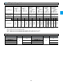
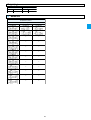
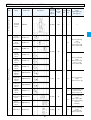
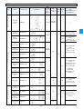
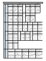
Piston pumps
Whole models
Model No.
V8
VZ series
V series
V15
V23
V38
V50
V70
VZ50
VZ63
VZ80
VZ100
VZ130
Piping
direction
Side port
Side port
Axial port
Side port
Axial port
A
R
R (L)
R (L)
R (L)
R (L)
A-RC
—
R (L)
R (L)
R (L)
R (L)
CH
—
R
—
R
—
Side port
Axial port
Side port
Side port
Side port
Side port
Side port
Side port
Side port
R (L)
R (L)
R (L)
R (L)
R
R
R
R
R
R (L)
R (L)
R (L)
R (L)
R
R
R
R
R
R
—
—
R
R
R
R
R
—
CH-RC
—
R
—
R
—
R
—
—
—
—
—
—
—
—
Control method
CJ
CJ-RC
—
—
R
R
—
—
R
R
—
—
R
R
—
—
—
—
—
R
R
R
R
—
—
—
—
—
—
—
D
—
R
—
R
—
R
—
—
D-RC
—
R
—
R
—
R
—
—
SA
—
R (L)
R (L)
R (L)
R (L)
R (L)
R (L)
R (L)
SAJS
—
—
—
R
—
R (L)
—
R (L)
—
—
—
—
—
—
—
—
—
—
—
—
R (L)
—
—
—
—
—
R
—
—
—
—
—
Note) In the table above, “R” and “L” stand for the direction of the rotation “Clockwise” and “Counterclockwise” with the view point from the shaft
end, respectively.
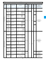
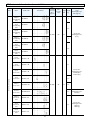
Models applied for incombustible working oil
Model
No.
V8
V15
V23
V38
V50
V70
Working oil
Working oil with water/glycol (W)
Working oil with phosphoric acid ester (F)
Working oil with water/glycol (W)
Working oil with phosphoric acid ester (F)
Working oil with water/glycol (W)
Working oil with phosphoric acid ester (F)
Working oil with water/glycol (W)
Working oil with phosphoric acid ester (F)
Working oil with water/glycol (W)
Working oil with phosphoric acid ester (F)
Working oil with water/glycol (W)
Working oil with phosphoric acid ester (F)
A
—
—
¡
¡
¡
¡
¡
¡
¡
¡
¡
¡
A-RC
—
—
¡
¡
¡
¡
¡
¡
¡
¡
¡
¡
CH
—
—
CH-RC
—
—
¡
¡
¡
¡
¡
¡
¡
¡
¡
¡
¡
¡
—
—
—
—
—
—
¡
¡
Note) There is no models applied for incombustible working oil in the VZ series.
Contact us for the applied conditions.
1
Control method
CJ
CJ-RC
—
—
—
—
¡
¡
¡
¡
¡
¡
¡
¡
¡
¡
¡
¡
—
—
—
—
—
—
—
—
D
—
—
¡
¡
¡
¡
¡
¡
—
—
—
—
D-RC
—
—
¡
¡
¡
¡
¡
¡
—
—
—
—
SA
—
—
¡
¡
¡
¡
¡
¡
¡
¡
¡
¡
SAJS
—
—
—
—
¡
—
¡
—
¡
—
¡
—
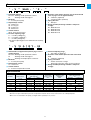
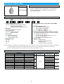
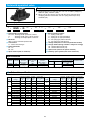
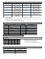
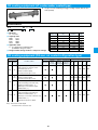
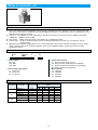
V series piston pump
Features
! Low noise
" Realized low noise operation in overall pressure area on each series.
! High efficiency
" Oil temperature rise can be reduced due to the less power-loss.
Accordingly, it is possible to design the tank in small size.
! High reliability
" High response, high stability, and long life make it possible to increase the reliability of the
main machine.
Nomenclature
! Pressure compensator control
* - V ** A * * * 1
2
3
4
5 12 15
**
**
16
17
! Combination control (Self pressure method)
* - V ** C * * R H X 1
2
3
4
7
8
12
13
15
**
**
16
17
! Combination control(Solenoid operated method)
* - V ** C * * R J * X 1
2
3
4
7
8
**
**
16
17
12 13 14 15
! Dual pressure control
* - V ** D * * R * X 1
2
3
4
9 10 12 14 15
**
**
16
17
! Power-match control
* - V ** SA * * * * 1
2
3
4
6
11
12
15
**
16
(1) Nomenclature of applied fluid (refer to page 1 for the
applied models)
No mark : Working oil with petroleum contents
W
: Working oil with water/glycol
F
: Working oil with phosphoric acid ester
(2) Model No.
V : V series piston pump
(3) Displacement volume
8 : 8.0cm3/rev
15 : 14.8cm3/rev
23 : 23.0cm3/rev
38 : 37.7cm3/rev
50 : 51.6cm3/rev
70 : 69.8cm3/rev
(4) Control method I (refer to page 1 for the applied
models)
A : Pressure compensator control
C : Combination control
D : Dual pressure control
SA : Power match control
(5)(6) Pressure adjusting range
(refer to the pressure adjusting range table)
(7)(9) Low pressure adjusting range
(refer to the pressure adjusting range table)
(8)(10) High pressure adjusting range
(refer to the pressure adjusting table)
(11) FC valve pressure differential
A : 0.7MPa {7kgf/cm2}
B : 1.4MPa {14kgf/cm2}
C : 2.1MPa {21kgf/cm2}
(12)Direction of the rotation from the view of the shaft
end (refer to page 1 for the applied models)
R : Clockwise (rightward)
L : Counterclockwise (leftward)
* Impossible to exchange “clockwise” to “counterclockwise”.
(13)Control method II
H : Self pressure method
J : Solenoid operated method
(14)Voltage for the solenoid operated valve
A : AC100V (50/60Hz), AC110V (60Hz)
B : AC200V (50/60Hz), AC220V (60Hz)
N : DC12V
P : DC24V
(15)Piping direction (refer to page 1 for the applied
models)
No mark : Axial port
X
: Side port
(16)Design number (the design number is subject to
change)
20 : Pump model No. V8, V50
95 : Pump model No. V15, V38
30 : Pump model No. V23
<In case that the control method is A, CH, or SA>
35 : Pump model No. V23
<In case that the control method I is CJ or D>
60 : Pump model No. V70
(17)Control method III
No mark : Without remote control system
RC
: With remote control system
2
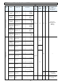
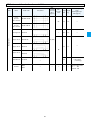
Pressure adjusting range table
! Pressure compensator control
(5) Pressure adjusting range
Mark
1
1
2
Without remote controller system
Pressure adjusting range
MPa {kgf/cm2}
V8
V15
¡
0.8~7 {8~70}
1.5~7 {15~70}
—
¡
¡
V38
¡
V70
V15
V23
V38
V50
V70
—
—
—
—
—
—
—
—
—
—
—
—
—
—
—
—
—
—
—
—
—
—
—
—
—
—
—
—
—
—
¡
—
—
—
—
—
—
—
—
—
—
—
—
—
¡
¡
¡
—
—
—
—
—
—
1.5~14 {15~140}
—
¡
1.5~21 {15~210}
2~21 {20~210}
—
—
—
—
3
3.5~21 {35~210}
1.5~25 {15~250}
—
—
—
3.5~25 {35~250}
—
—
¡
¡
¡
—
¡
¡
With remote controller system
V50
—
3
3
4
4
V23
¡
¡
¡
—
¡
¡
¡
¡
¡
¡
¡
¡
! Combination control
(7) Low pressure adjusting range
Mark
2
MPa {kgf/cm }
1
1
2
1.5~7 {15~70}
2.5~7 {25~70)
1.5~14 {15~140}
2
2.5~14 {25~140}
Solenoid operated valve method
Self pressure method
V23
V38
V70
—
—
—
—
—
Pressure adjusting range
V15
—
¡
—
¡
¡
¡
¡
¡
¡
V15
V23
V38
—
—
—
—
—
—
¡
¡
¡
¡
—
¡
¡
¡
(8) High pressure adjusting range
Mark
1
1
2
2
3
4
Pressure adjusting range
2
MPa {kgf/cm }
1.5~7 {15~70}
2.5~7 {25~70}
1.5~14 {15~140}
2.5~14 {25~140}
3.5~21 {35~210}
3.5~25 {35~250}
V15
—
¡
Self pressure method
V23
V38
—
—
—
¡
¡
—
¡
¡
—
—
¡
¡
¡
¡
¡
¡
Solenoid operated valve method
V15
V23
V38
V70
¡
¡
¡
—
¡
—
—
—
—
—
—
—
—
—
¡
¡
¡
¡
¡
¡
¡
¡
¡
¡
! Dual pressure control
(9) Low pressure adjusting range
Mark
1
2
Pressure adjusting range
MPa {kgf/cm2}
(10) High pressure adjusting range
V15
V23
V38
¡
¡
¡
¡
¡
¡
1.5~7 {15~70}
1.5~14 {15~140}
Mark
1
2
3
4
Note) If both low and high pressure adjusting range are the
pattern 1, the addjusting pressure range becomes
0.8~7MPa {8~70kgf/cm2}.
! Power match control
(6) Pressure adjusting range
Mark
1
1
2
3
4
Pressure adjusting range
MPa {kgf/cm2}
0.8~7 {8~70}
1.5~7 {15~70}
1.5~14 {15~140}
3.5~21 {35~210}
3.5~25 {35~250}
V15
V23
V38
V50
V70
—
—
—
—
¡
¡
¡
—
—
—
¡
¡
—
¡
¡
¡
¡
¡
¡
¡
¡
¡
¡
¡
¡
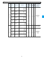
3
Pressure adjusting range
MPa {kgf/cm2}
1.5~7 {15~70}
1.5~14 {15~140}
3.5~21 {35~210}
3.5~25 {35~250}
V15
V23
V38
¡
¡
¡
¡
¡
¡
¡
¡
¡
¡
¡
—
Nomenclature
* - V ** SAJS - * * X 1
2
3
4
5
6
**
8
7
(1) Fluid mark applied
No mark : Working oil with petroleum contents
W
: Working oil with water/glycol
(2) Model No.
V : V series piston pump
(3) Displacement volume
23 : 23.0cm3/rev
38 : 37.7cm3/rev
50 : 51.6cm3/rev
70 : 69.8cm3/rev
(4) Control method
SAJS : Power match control
(5) Pressure adjusting range
A :*~14 MPa {140kgf/cm2}
B :*~17.5 MPa {175kgf/cm2}
C :*~21 MPa {210kgf/cm2}
* The lowest adjusting pressure is different from model by
model.
(6) Direction of the rotation from the view of the shaft end
(refer to page 1 for the applied models)
R : Clockwise (rightward)
L : Counterclockwise (leftward)
(7) Piping direction
X : Side port
(8) Design number (the design number is subject to
change)
30 : Model No. V23
95 : Model No. V38
20 : Model No. V50
60 : Model No. V70
* - V 15 A 1 R Y - 95
1
2
3
4
5
6
7
8
(1) Nomenclature of applied fluid (refer to page 1 for the
models applied)
No mark : Working oil with petroleum contents
W
: Working oil with water/glycol
F
: Working oil with phosphoric acid ester
(2) Model No.
V : V series piston pump
(3) Displacement volume
15 : 14.8cm3/rev
(4) Control method
A : Pressure compensation control
(5) Pressure adjusting range
1 : 0.8~7MPa {8~70kgf/cm2}
(6) Direction of the rotation (from the view of the shaft
end)
R : Clockwise (rightward)
(7) Piping connection
Y : Suction connection : Flange
Discharge connection : Taper screw for tube use
(8) Design number (the design number is subject to
change)
Specifications
Model No.
Theoretical
displacement
cm3/rev
V8
V15
V15 (Y type)
8.0
14.8
14.8
V23
V38
V50
23.0
37.7
51.6
V70
69.8
Operating pressure
MPa {kgf/cm2}
Max.
Rating
7 {70}
7 {70}
21 {210}
14 {140}
7 {70}
25 {250}
25 {250}
7 {70}
17.5 {175}
17.5 {175}
21 {210}
21 {210}
14 {140}
14 {140}
Permissible
rotation speed
min-1
500~1800
500~1800
500~1800
500~1800
500~1800
500~1800
500~1800
Weight
(with control method A)
kg
Displacement
adjusting range
1800min-1
L/min
Axial port
Side port
4~14.4
5.6~26.6
—
12.8
8.9
14.5
13.5
5.6~26.6
11~41.4
28~68
0~93
18.4
24.4
—
21.5
26
50
20~126
—
55
Note) JR-G(T)02 and JRP-G02 are recommended for the relief valve of the remote control system.
When the vent port is blocked, the pressure compensation structure doesn’t work, and it comes to be a fixed pump state.
!Since foot is not attached to the pump, you might order it separately in at your use.
4
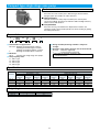
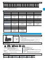
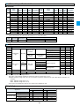
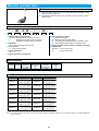
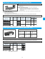
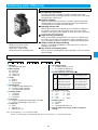
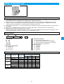
VZ series piston pump
Features
! High density of displacement
The adoption of a cradle swash plate makes it possible to cope with both
compactness and high pressure. Accordingly, the output per an unit
weight has been increased.
! Low operation noise
The increased stiffness of the swash structure and the housing shape,
which has been developed by the latest measurement and analysis
technologies, make the operation noise reduce extremely.
! High efficiency
The spherical valve plate and the suitable oil pressure balance enable it to
keep a steady state under the broad range of the operative conditions,
resulting in high efficiency.
! Long life
The adoption of the spherical valve plate with a superior abrasion resistance makes it possible to strengthen anti-contaminant characteristics.
Nomenclature
! Pressure compensator control
VZ
***
1
2
A * R X - 10
3
4
7
**
11
10
12
! Combination control
VZ
***
1
2
C * * R * * X — 10
3
5
6
7
8
9
11
10
(1) Model No.
VZ : VZ series piston pump
(2) Displacement volume
50 : 50.2cm3/rev
63 : 63.0cm3/rev
80 : 79.6cm3/rev
100 : 104.6cm3/rev
130 : 135.9cm3/rev
(3) Control method I (refer to page 1 for the models
applied )
A : Pressure compensator control
C : Combination control
(4) Pressure adjusting range
1 : 1.5~7MPa {15~70kgf/cm2}
2 : 1.5~14MPa {15~140kgf/cm2}
3 : 3.5~21MPa {35~210kgf/cm2}
4 : 3.5~28MPa {35~280kgf/cm2} ★1
(5) Low pressure adjusting range
1 : 1.5~7MPa {15~70kgf/cm2}
2 : 1.5~14MPa {15~140kgf/cm2}
3 : 3.5~21MPa {35~210kgf/cm2}
4 : 3.5~28MPa {35~280kgf/cm2} ★1
(6) High pressure adjusting range
1 : 1.5~7MPa {15~70kgf/cm2}
2 : 1.5~14MPa {15~140kgf/cm2}
3 : 3.5~21MPa {35~210kgf/cm2}
4 : 3.5~28MPa {35~280kgf/cm2} ★1
(7) Direction of the rotation (from the view of the shaft
end)
R : Clockwise (rightward)
(8) Control method II
H : Self pressure method
J : Solenoid operated valve method
(9) Voltage mark for the solenoid operated valve
< Only be applied for the case that the control method
II is J >
A : AC100V (50/60Hz), AC110V (60Hz)
B : AC200V (50/60Hz), AC220V (60Hz)
P : DC24V
(10)Piping direction
X : Side port
(11)Design number (design number is subject to change)
(12)Control method III
No mark : Without remote control system
RC
: With remote control system ★2
<Only be applied for the case that the control
method I is A>
Note) ★1 The 4th pattern of the pressure adjusting range (3.5~28MPa {35~280kg/cm2}) is only applied for VZ50, 63, 80, 100.
★2 The pressure adjusting range with remote control system is the 4th pattern only (but 3rd pattern for VZ130).
Specifications
Model No.
VZ50
VZ63
VZ80
VZ100
VZ130
Theoretical
displacement
cm3/rev
50.2
63.0
79.6
104.6
135.9
Operating pressure
MPa {kgf/cm2}
Max.
Rated
28 {280}
25 {250}
28 {280}
25 {250}
28 {280}
25 {250}
28 {280}
25 {250}
21 {210}
17.5 {175}
Permissible
rotation speed
min-1
Displacement
adjusting range
1800min-1
L/min
Weight
(control method : A)
kg
500~1800
500~1800
500~1800
500~1800
500~1800
0~90
0~113
0~143
0~188
0~244
40
47
55
75
105
5
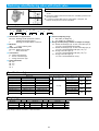
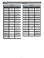
Motor pumps
Whole models
Model
No.
M8
M15
M23
M38
Piping direction
Side port
Side port
Axial port
Side port
Axial port
Side port
Axial port
Control method
A
¡
¡
¡
¡
¡
¡
¡
A-RC
—
CH
—
CH-RC
—
CJ
—
CJ-RC
—
D
—
D-RC
—
—
—
—
—
—
—
—
—
—
—
—
—
—
—
—
—
—
—
¡
¡
¡
¡
¡
¡
D
—
—
D-RC
—
—
SA
—
—
¡
¡
¡
¡
¡
¡
¡
¡
¡
¡
¡
¡
¡
¡
¡
¡
¡
¡
¡
¡
¡
¡
¡
¡
SA
—
Models applied for incombustible working oil
Model
No.
M8
M15
M23
M38
Working oil
Working oil with water/glycol (W)
Working oil with phosphoric acid ester (F)
Working oil with water/glycol (W)
Working oil with phosphoric acid ester (F)
Working oil with water/glycol (W)
Working oil with phosphoric acid ester (F)
Working oil with water/glycol (W)
Working oil with phosphoric acid ester (F)
A
—
—
¡
¡
¡
¡
¡
¡
A-RC
—
—
CH
—
—
¡
¡
¡
¡
¡
¡
¡
¡
¡
¡
¡
¡
Note) Contact us for the applied conditions.
6
Control method
CJ
CJ-RC
—
—
—
—
CH-RC
—
—
¡
¡
¡
¡
¡
¡
¡
¡
¡
¡
¡
¡
¡
¡
¡
¡
¡
¡
¡
¡
¡
¡
¡
¡
¡
¡
¡
¡
¡
¡
¡
¡
¡
¡
¡
¡
M series motor pump
Nomenclature
! Pressure compensator control
* - M ** A * * 1
2
3
4
5
**
-
**
17
15
-
**
12
16
! Combination control (Self pressure method)
* - M ** C * * H X - **
1
2
3
4
7
8
13
15
-
**
17
-
**
12
16
! Combination control (Solenoid operated valve)
* - M ** C * * J * X - **
1
2
3
4
7
8
-
**
17
13 14 15
-
**
12
16
! Dual pressure control
* - M ** D * * * X 1
2
3
4
9
10
14 15
**
-
17
**
12
-
**
16
! Power-match control
* - M **
1
2
3
SA * * * 4
6
11 15
**
-
12
**
16
(1) Nomenclature of applied fluid (refer to page 6 for the
models applied)
No mark : Working oil with petroleum contents
W
: Working oil with water/glycol
F
: Working oil with phosphoric acid ester
(2) Model No.
M : M series motor pump
(3) Displacement volume
8 : V8 (8.0cm3/rev)
15 : V15 (14.8cm3/rev)
23 : V23 (23.0cm3/rev)
38 : V38 (37.7cm3/rev)
(4) Control method I (refer to page 6 for the applied
models)
A : Pressure compensator control
C : Combination control
D : Dual pressure control
SA : Power-match control
(5)(6) Pressure adjusting range
(refer to the pressure adjusting range table)
(7)(9) Low pressure adjusting range
(refer to the pressure adjusting range table)
(8)(10) High pressure adjusting range
(refer to the pressure adjusting range table)
(11)FC valve differential pressure
A : 0.7MPa {7kgf/cm2}
B : 1.4MPa {14kgf/cm2}
C : 2.1MPa {21kgf/cm2}
(12)Power output mark of motor (refer to the specifications of motor)
(13)Control method II
H : Self pressure method
J : Solenoid operated valve method
(14)Voltage mark for solenoid operated valve
A : AC100V (50/60Hz), AC110V (60Hz)
B : AC200V (50/60Hz), AC220V (60Hz)
N : DC12V
P : DC24V
(15)Piping direction (refer to page 6 for the applied
models)
No mark : Axial port
X
: Side port
(16)Design number (the design number is subject to
change)
50 : Motor type M8
90 : Pump type M15
60 : Pump type M23
70 : Pump type M38
(17)Control method III (refer to page 6 for the applied
models)
No mark : Without remote control system
RC
: With remote control system
7
Pressure adjusting range table
! Pressure compensator control
(5) Pressure adjusting range
Mark
Without remote control system
M8
M15
M23
M38
Pressure adjusting range
MPa {kgf/cm2}
1
0.8~7 {8~70}
¡
2
3
1.5~14 {15~140}
1.5~21 {15~210}
—
—
3
3.5~21 {35~210}
—
¡
¡
¡
¡
¡
¡
—
—
—
¡
¡
With remote control system
M15
M23
M38
—
—
—
—
—
—
—
—
—
¡
¡
¡
¡
! Combination control
(7) Low pressure adjusting range
Mark
Pressure adjusting range
MPa {kgf/cm2}
1
1.5~7 {15~70}
1
2
2.5~7 {25~70}
1.5~14 {15~140}
2
2.5~14 {25~140}
Self pressure method
M15
M23
M38
—
—
¡
—
¡
—
¡
—
¡
Solenoid operated valve method
M15
M23
M38
¡
¡
—
—
—
—
—
¡
—
¡
¡
—
¡
¡
¡
(8) High pressure adjusting range
Mark
Pressure adjusting range
MPa {kgf/ cm2}
1
1
1.5~7 {15~70}
2.5~7 {25~70}
2
2
3
1.5~14 {15~140}
2.5~14 {25~140}
3.5~21 {35~210}
Solenoid operated valve method
Self pressure method
M15
M23
M38
—
—
—
¡
¡
¡
—
—
—
¡
¡
¡
¡
M15
M23
M38
—
—
—
—
—
—
¡
¡
¡
¡
¡
¡
¡
¡
¡
¡
¡
! High pressure adjusting range
(9) Low pressure adjusting range
Mark
1
2
Pressure adjusting range
MPa {kgf/cm2}
(10) High pressure adjusting range
M15
M23
M38
¡
¡
¡
¡
¡
¡
1.5~7 {15~70}
1.5~14 {15~140}
Mark
1
2
3
Pressure adjusting range
MPa {kgf/cm2}
1.5~7 {15~70}
1.5~14 {15~140}
3.5~21 {35~210}
M15
M23
M38
¡
¡
¡
¡
¡
¡
¡
¡
¡
Note) If both low and high pressure adjusting range are the pattern 1, the adjusting pressure range becomes 0.8~7MPa {8~70kgf/cm2}.
! Power-match control
(6) Pressure adjusting range
Mark
Pressure adjusting range
MPa {kgf/cm2}
0.8~7 {8~70}
1
2
3
1.5~14 {15~140}
3.5~21 {35~210}
M15
M23
M38
¡
¡
¡
¡
¡
¡
¡
¡
¡
(12) : Motor output and specifications
Mark
Output/Pole number
kW/4P
05
1
2
0.4
0.75
1.5
3
2.2
5
3.7
7
5.5
10
7.5
Motor rated ampere A
Weight
Applied models
200V (50Hz)
2.2
3.8
200V (60Hz)
2.0
3.4
220V (60Hz)
2.0
3.4
6.8
9.3
8.9
15.0
15.0
22.0
28.0
6.2
8.8
8.5
14.0
14.0
20.0
28.0
6.0
8.3
7.9
13.2
13.0
20.0
26.0
3
8
M8
¡
¡
¡
—
—
—
—
—
—
M15
—
¡
¡
¡
—
¡
—
—
—
kg
9
14.5
23.5
M23
—
—
M38
—
—
—
—
—
—
¡
32
—
—
44
45
67
77
¡
¡
¡
¡
¡
¡
¡
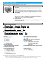
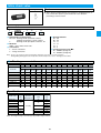
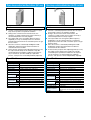
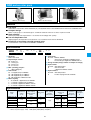
RP series rotor pump
! Variable displacement pump integrated in electric motor.
Features
! Low Noise
The adoption of our own low noise technology realizes to reduce the operation noise so
great as 10~15dB (in comparison with our own products) and improve the sound quality.
! Compactness
The one housing structure enables it to shorten the length so much as 40% in comparison with our existing models. It results in easy handling and compactness of the machine.
! Low pulsation
The pulsation has reduced by 50% in comparison with our existing models.
! High reliability
Because of the hermetic structure such that the shaft is not out of the casing, it doesn’t
need an oil seal and no oil leak will happen. Besides, the temperature rise in the motor
coil is small due to the motor oil cooling structure. Consequently, the structure makes it
possible to operate pumps in a long term overload conditions.
! Coping with CE
Since these models are equipped with the terminal box of IP54 based on the International
Standards (IEC34-1 and others), the models are the best suited for coping with the
Europe safety standards (CE).
Nomenclature
! Pressure compensator control
RP
**
1
2
A * 3
**
9
4
* - 30
**
11
12
10
- *
13
! Combination control (Self pressure method)
RP
1
** C * * H 2
3
5
6
**
9
7
* - 30
11
10
! Combination control (Self operated valve method)
RP
1
** C * * J * 2
3
5
6
7
8
**
9
* - 30
10
(1) Model No.
RP : RP series rotor pumps
(2) Displacement volume
08 : 8.0cm3/rev
15 : 14.8cm3/rev
23 : 24.4cm3/rev
38 : 37.7cm3/rev
(3) Control method I
A : Pressure compensator control
C : Combination control
(4) Pressure adjusting range
(refer to the pressure adjusting range table)
(5) Low pressure adjusting range
1 : 2.5~7MPa {25~70kgf/cm2}
2 : 2.5~14MPa {25~140kgf/cm2}
(6) High pressure adjusting range
1 : 2.5~7MPa {25~70kgf/cm2}
2 : 2.5~14MPa {25~140kgf/cm2}
3 : 3.5~21MPa {35~210kgf/cm2}
(7) Control method II
H : Self pressure method
J : Solenoid operated valve method
11
(8) Voltage for the solenoid operated valve
A : AC100V (50/60Hz), AC110V (60Hz)
B : AC200V (50/60Hz), AC220V (60Hz)
P : DC24V
(9) Motor output (refer to the motor specifications)
(10)Voltage specifications
No mark : AC200V (50/60Hz), AC220V (60Hz)
X
: AC230V (50Hz)
Y
: AC380V (50Hz), AC400V (50/60Hz)
AC415V (50Hz), AC440V (60Hz)
AC460V (60Hz)
(11)Design number (design number is subject to change)
(12)Control method III
No mark : Without remote control system
RC
: With remote control system
(13)Pump installations
No mark : Foot installation
T
: Vertical installation ★1
Note) ★1 The type of the vertical installation is only applied to RP08 or RP15.
★1 Since the vertical installation type doesn’t effectively use antivibration pads, you might let the installation space have a sufficient
stiffness so as to apply the structure absorbing vibration. The insufficient stiffness may cause noise or vibration, etc..
9
(4) : Pressure adjusting range table (pressure compensator control)
Mark
Pressure adjusting range
MPa {kgf/cm2}
Without remote control system
RP08
1
1.5~7 {15~70}
¡
1
2.0~7 {20~70}
—
2
1.5~14 {15~140}
¡
2
3
3
2.0~14 {20~140}
2.0~21 {20~210}
3.5~21 {35~210}
—
—
—
Note) ★1
★2
★3
★4
RP15
¡
RP23
¡
—
—
—
★2
¡
¡
—
¡
With remote control system
RP38
—
—
★3
¡
RP15
RP23
RP38
—
—
—
—
—
—
—
—
—
—
¡
—
¡
RP08
¡
—
—
—
★4
—
—
¡
¡
¡★1
¡★2
¡★2
¡★3
¡
¡★4
—
—
—
Applied only to a electrical motor output 1.5 kW.
Applied only to a electrical motor output 2.2 kW.
Applied only to a electrical motor output 3.7 kW.
Applied only to a electrical motor output 5.5 kW.
(9) : Electrical motor output
Mark
Output/Pole number
07
15
22
kW/4P
0.75
1.5
2.2
37
55
3.7
5.5
Insulation type
RP08
¡
—
E type
—
—
—
Models applied
RP15 RP23 RP38
—
—
—
—
—
¡
¡
—
—
¡
¡
—
—
¡
¡
Specifications
Model code
RP08A*-07-30 (RC)
RP15A*-15-30 (RC)
RP15A*-22-30 (RC)
RP15C**H (J)-15-30
Theoretical
displacement
cm3/rev
8.0
14.8
RP15C**H (J)-22-30
RP23A*-22-30 (RC)
RP23A*-37-30 (RC)
RP23C**H (J)-22-30
24.4
RP23C**H (J)-37-30
RP38A*-37-30 (RC)
RP38A*-55-30 (RC)
RP38C**H (J)-37-30
RP38C**H (J)-55-30
37.7
Pumps
Max. operating
Displacement adjusting range
pressure
60Hz
2
MPa {kgf/cm }
L/min
14 {140} ★1
4.8~14.0
14 {140}
12.0~25.0
21 {210}
Large capacity adjusting range
12.0 ~ 25.0
21 {210}
Small capacity adjusting range
1.0 ~ 10.0
14 {140}
20.0~42.0
21 {210}
A
21 {210}
B
14 {140}
20.0~64.0
21 {210}
Large capacity adjusting range
30.0 ~ 64.0
21 {210}
Small capacity adjusting range
1.0 ~ 25.0
Motor
Rating amperes A
Weight
kg
Out/Pole
number
kW/4P
0.75
1.5
2.2
1.5
200V (50HZ)
3.8
6.8
9.6
6.8
200V (60HZ)
3.4
6.0
8.8
6.0
220V (60HZ)
3.4
5.8
8.4
5.8
2.2
9.6
8.8
8.4
2.2
3.7
2.2
10.0
15.1
10.0
15.1
9.2
14.7
9.2
14.7
8.7
13.4
8.7
13.4
15.1
22.0
14.7
21.2
13.4
19.6
3.7
15.1
14.7
13.4
87
H:76 (J:78)
5.5
22.0
21.2
19.6
H:90 (J:92)
3.7
3.7
5.5
30
45
H:50 (J:52)
67
73
H:70 (J:72)
H:76 (J:78)
73
Note) ★1 There is a restriction of application condition for using in a range of 7~14MPa (70~140kgf/cm2).
"
JR-G (T) 02 and JRP-G02 are recommended for a relief valve of remote control system.
When the vent port is blocked, the pressure compensation structure doesn’t work, and it comes to be a fixed pump state. So, a
relief valve should be connected at the discharge of the pump.
A:
RP23-22 Large capacity adjusting range 20.0~42.0 Small capacity adjusting range 1.0~15.0
B:
RP23-37 Large capacity adjusting range 30.0~42.0 Small capacity adjusting range 1.0~25.0
10
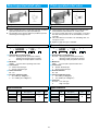
Compact type single stage vane pump
Features
! Low noise
Since the size of the suction port is wide enough, small resistance
through suction port enables to realize low noise.
! High efficiency
The side clearance is always kept constant by the cushion plate
system. Accordingly, the pump can maintain stable and high efficiency
without seizure and abrasion.
! Low pulsation
Since the cam ring can minimize the displacement variation, the
operation sound is quiet and the pulsation is small, resulting in gaining
the stable performance.
Nomenclature
* - DS ** P - 20
1
2
3
2
- *
4
5
(1) Nomenclature of applied fluid
No mark : Working oil with petroleum contents,
Working oil with water/glycol contents
Working oil with W/O emulsion contents
F
: Working oil with phosphoric acid ester
(2) Model No.
DS_P
: Compact type single stage vane pumps
(3) Pump capacity code
11 : DS 11 type
12 : DS 12 type
13 : DS 13 type
14 : DS 14 type
(4) Design number (the design number is subject to
change)
(5) Direction of the rotation from the view of the shaft end
No mark : Clockwise (rightward)
L
: Counterclockwise (leftward)
* Impossible to exchange “clockwise” with
“counterclockwise”.
Specifications
[Conditions] Input revolving speed: 1800min-1
Model No.
0.4MPa
{4kgf/cm2}
3MPa
{30kgf/cm2}
DS 11P
DS 12P
DS 13P
5.0
7.7
12.6
DS 14P
22.1
Shaft power input kW
4.5
7.2
11.8
5MPa
{50kgf/cm2}
4.1
6.7
11.5
7MPa
{70kgf/cm2}
3.9
6.5
11.0
0.4MPa
{4kgf/cm2}
0.15
0.20
0.25
1MPa
{10kgf/cm2}
0.28
0.40
0.50
3MPa
{30kgf/cm2}
0.55
0.75
1.05
5MPa
{50kgf/cm2}
0.82
1.12
1.55
7MPa
{70kgf/cm2}
1.1
1.5
2.1
21.2
20.5
20.0
0.35
0.77
1.65
2.50
3.4
Weight (kg)
Pump's type
DS1*P
Working oil : Equivalent to ISO VG32 Oil temp: 40˚C
Displacement L/min
Flange connection type
3
Foot mounting type
4.4
11
Single stage vane pump
Features
! Low noise and low pulsation
Since the cam ring which enables to minimize the displacement
variation, the operation sound is quiet and the pulsation is small,
resulting in gaining the stable performance.
! High reliability
Good pressure balance can be kept due to the structure which
maintains complete oil equalization. As a result, a long life is promised
because an eccentric load will not be on the shaft and bearing.
Nomenclature
* - DV * * 2
1
3
* V - 20 5
4
6
*
7
(1) Nomenclature of applied fluid
No mark : Working oil with petroleum contents,
Working oil with water/glycol contents
Working oil with W/O emulsion contents
F
: Working oil with phosphoric acid ester
(2) Model No.
DV
: Single stage vane pump
(3) Pump capacity code
S : Small type
M : Middle type
L : Large type
(4) Connection types
F : Flange connection type
B : Foot mounting type
(5) Displacement mark (refer to the specification table)
(6) Design number (the design number is subject to
change)
(7) Direction of the rotation from the view of the shaft end
No mark : Clockwise (rightward)
L
: Counterclockwise (leftward)
Note) DVL*type: Flanges for the connection to suction and to discharge, and O-rings and bolts are attached to pumps.
Specifications
[Conditions] Power input revolving speed: 1200min-1
Model No.
DVS*-1V
DVS*-2V
DVS*-3V
DVS*-4V
DVS*-5V
DVS*-6V
DVM*-1V
DVM*-2V
DVM*-3V
DVM*-4V
DVM*-5V
DVL*-2V
DVL*-3V
DVL*-4V
Working oil : Equivalent to ISO VG32 Oil temp: 40˚C
Displacement L/min
0.4MPa
{4kgf/cm2}
3MPa
{30kgf/cm2}
6.4
9.0
13.5
19.5
33.0
43.0
57.0
72.0
87.0
108.0
140.0
164.0
207.0
226.0
5.9
8.4
12.6
18.8
32.2
42.2
55.5
70.0
85.0
106.0
137.0
157.0
200.0
219.0
5MPa
{50kgf/cm2}
5.4
8.0
12.3
18.4
31.6
41.6
53.8
68.5
83.5
104.5
135.5
152.0
196.0
216.0
Shaft power input kW
7MPa
{70kgf/cm2}
5.0
7.5
12.0
18.0
31.0
41.0
52.0
67.0
82.0
103.0
134.0
148.0
192.0
208.0
Weight (kg)
Pump's type
DVS *
DVM *
Flange connection type
10
26
DVL *
107
Foot mounting type
11
28
110
Note) Weight of DVL* includes piping connection flange and bolts.
12
0.4MPa
{4kgf/cm2}
0.2
0.2
0.22
0.25
0.33
0.45
0.5
0.8
1.2
1.6
2.1
3.2
3.8
4.8
1MPa
{10kgf/cm2}
0.3
0.4
0.5
0.6
1.0
1.3
1.6
2.2
2.7
3.6
4.6
6.2
7.5
8.8
3MPa
{30kgf/cm2}
0.7
0.8
1.1
1.4
2.3
2.9
3.8
4.8
6.2
7.8
9.5
11.6
15.0
16.7
5MPa
{50kgf/cm2}
1.0
1.3
1.7
2.3
3.6
4.5
6.0
7.7
9.6
11.9
14.3
17.3
22.5
24.8
7MPa
{70kgf/cm2}
1.4
1.7
2.4
3.2
4.9
6.2
8.5
10.5
13.0
16.0
19.0
23.0
28.3
31.5
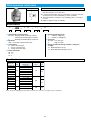
MFP100 series motor pump
! This is a motor pump that TFP type gear pump and electrical
motor are built in one body.
Nomenclature
MFP100 /
**
1
2
- 2 - * 3
10
5
4
(1) Model No.
MFP100 : MFP100 series motor pump
(2) Displacement volume
1.2 : 1.2cm3/rev
1.7 : 1.7cm3/rev
2.2 : 2.2cm3/rev
2.6 : 2.6cm3/rev
3.2 : 3.2cm3/rev
3.8 : 3.8cm3/rev
4.3 : 4.3cm3/rev
7.8 : 7.8cm3/rev
(3) Voltage specifications
2 : AC200V (50/60Hz), AC220V (60Hz)
(4) Motor power output
0.4 : 0.4kW/4P
0.75 : 0.75kW/4P
1.5 : 1.5kW/4P
2.2 : 2.2kW/4P
(5) Design number (the design number is subject to
change)
Specifications
Model code
Gear pump type
MFP 100/1.2-2-*-10
MFP 100/1.7-2-*-10
MFP 100/2.2-2-*-10
MFP 100/2.6-2-*-10
MFP 100/3.2-2-*-10
MFP 100/3.8-2-*-10
MFP 100/4.3-2-*-10
MFP 100/7.8-2-*-10
TFP 100/1.2DCI06
TFP 100/1.7DCI06
TFP 100/2.2DCI06
TFP 100/2.6DCI06
TFP 100/3.2DCI06
TFP 100/3.8DCI06
TFP 100/4.3DCI06
TFP 100/7.8DCI06
0.4
¡
¡
¡
¡
¡
¡
¡
—
Motor
kW/4P
0.75 1.5
¡
¡
¡
¡
¡
¡
¡
¡
¡
¡
¡
¡
¡
¡
¡
¡
2.2
—
—
¡
¡
¡
¡
¡
¡
(4) : Motor power output/Specifications
Mark
0.4
0.75
1.5
2.2
Output/Pole number
kW/4p
0.4
0.75
1.5
2.2
200V (50Hz)
2.4
3.7
6.8
9.6
Motor rated amperes A
200V (60Hz)
220V (60Hz)
2.1
2.1
3.4
6.2
9.0
3.3
6.3
8.4
13
Operating pressure
MPa {kgf/cm2}
Max.
Rated
21{210}
14 {140}
18 {180}
10.5 {105}
Theoretical displacement
cm3/rev
1.2
1.7
2.2
2.6
3.2
3.8
4.3
7.8
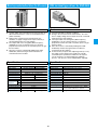
Direct operated relief valve (for remote control)
Direct operated relief valve
JIS symbols
JIS symbols
Features
Features
! This valve is used in remote control mode after connecting
to a vent port of a pilot operated pressure control valve
such as a relief valve, a reducing valve, etc..
! As the override pressure is small, this valve has almost
equivalent performance to a pilot operated type.
! The vibration proof structure makes it possible to prevent
chattering even in high pressure.
! Broad range of adjusting is possible and pressure
adjusting in low pressure area is easy to do.
Nomenclature
Nomenclature
* - JR - * 02 - * - 22 - *
1
2
3
4
5
6
SR - * 03 - 1 -
7
1
(1) Nomenclature of applied fluid
No mark : Working oil with petroleum contents,
Working fluid with water/glycol contents
F
: Working oil with phosphoric acid ester
(2) Model No.
JR : J series direct operating relief valve
(3) Connections
G : Gasket attached type
T : Screw connection type
(4) Nominal diameter
02 : 1/4
(5) Pressure adjusting range
1 : 0.8~7MPa {8~70kgf/cm2}
3 : 3.5~21MPa {35~210kgf/cm2}
(6) Design number (the design number is subject to
change)
(7) Option mark
No mark : Pressure adjusting handle type
T
: Pressure adjusting bolt type ★1
2
3
4
**
5
(1) Model No.
SR : S series direct operating relief valves
(2) Connections
G : Gasket attached type
T : Screw connection type
(3) Nominal diameter
03 : 3/8
(4) Pressure adjusting range
1 : 0.3~7MPa {3~70kgf/cm2}
(5) Design number (design number is subject to change)
12 : Screw connection type (T)
13 : Gasket attached type (G)
Note) ★1 The pressure adjusting type is only applied to the Gasket
attached type (G).
Specifications
Model code
JR-G02-1-22
JR-G02-3-22
JR-T02-1-22
JR-T02-3-22
Nom.
Dia.
1/4
Pressure adjusting range
MPa {kgf/cm2}
0.8~7 {8~70}
3.5~21 {35~210}
0.8~7 {8~70}
3.5~21 {35~210}
Specifications
Max. flow rate Weight
L/min
kg
1.2
1.5
14
Model code
Nom.
Dia.
Pressure adjusting range
MPa {kgf/cm2}
SR-G03-1-13
SR-T03-1-12
3/8
0.3~7 {3~70}
Max. flow rate Weight
L/min
kg
2.5
30
2
Direct operated relief valve
Pilot operated relief valve
JIS symbols
JIS symbols
Features
Features
! As the override pressure is small, this valve has an almost
equivalent performance to a pilot operated type.
! The vibration proof structure makes it possible to prevent
chattering even in high pressure.
! The broad flow rate range enables the steady pressure
control and this valve actuates as a safety valve.
! If a remote control relief valve is connected to a vent port,
the main circuit pressure can be controlled by a remote
controller.
! This valve will have a function of an unloading valve, if a
vent port is used.
! Option for high vent type is available.
Nomenclature
Nomenclature
* - HDRIR - * 02 - *
1
2
3
4
* - HDRI - * 03 - * *
5
1
(1) Nomenclature of applied fluid
No mark : Working oil with petroleum contents,
Working oil with water/glycol contents
F
: Working oil with phosphoric acid ester
(2) Model No.
HDRIR : H series direct operating relief valve
(3) Connections
G : Gasket attached type
T : Screw connection type
(4) Nominal diameter
02 : 1/4
(5) Pressure adjusting range
1 : 0.9~7MPa {9~70kgf/cm2}
3 : 3.5~21MPa {35~210kgf/cm2}
HDRIR-G02-1
HDRIR-G02-3
HDRIR-T02-1
HDRIR-T02-3
Nom.
Dia.
1/4
Pressure adjusting range
MPa {kgf/cm2}
0.9~7 {9~70}
3.5~21 {35~210}
0.9~7 {9~70}
3.5~21 {35~210}
3
4
5
6
(1) Nomenclature of applied fluid
No mark : Working oil with petroleum contents,
Working oil with water/glycol contents
F
: Working oil with phosphoric acid ester
(2) Model No.
HDRI
: H series pilot operated relief valve
(3) Connections
G : Gasket attached type
T : Screw connection type
(4) Nominal diameter
03 : 3/8
(5) Pressure adjusting range
1 : 0.5~7MPa {5~70kgf/cm2}
3 : 3.5~21MPa {35~210kgf/cm2}
(6) Vent mark
No mark : Low vent type
V
: High vent type
Specifications
Model code
2
Specifications
Max. flow rate Weight
L/min
kg
Model code
HDRI-G03-1
HDRI-G03-3
HDRI-T03-1
HDRI-T03-3
2.6
12
1.8
15
Nom.
Dia.
3/8
Pressure adjusting range
MPa {kgf/cm2}
0.5~7 {5~70}
3.5~21 {35~210}
0.5~7 {5~70}
3.5~21 {35~210}
Max. flow rate Weight
L/min
kg
3.5
30
2.9
Pilot operated relief valve
Features
JIS symbols
! The broad flow rate range enables the steady pressure control and
this valve actuates as a safety valve.
! If a remote control relief valve is connected to a vent port, the main
circuit pressure can be controlled by a remote controller.
! This valve will have a function of an unloading valve, if a vent port
is used.
! Option as high vent type is available.
Nomenclature
* - JRB 1
2
* **
3
4
-
* *
5
-
6
**
7
(1) Nomenclature of applied fluid
No mark : Working oil with petroleum contents,
Working oil with water/glycol contents
F
: Working oil with phosphoric acid ester
(2) Model No.
JRB : J series pilot operated relief valve
(3) Connections
G : Gasket attached type
T : Screw connection type
F : Flange connection type
(4) Nominal diameter
06 : 3/4
10 : 11/4
16 : 2
(5) Pressure adjusting range
1 : *~7MPa {*~70kgf/cm2}
3 : *~21MPa {*~210kgf/cm2}
(6) Vent mark
No mark : Low vent type
V
: High vent type
(7) Design number (the design number is subject to
change)
12 : Nominal diameter 16 (2)
13 : Nominal diameter 06 (3/4), 10 (11/4)
Specifications
Model code
JRB-G06-1-13
JRB-G06-3-13
JRB-T06-1-13
JRB-T06-3-13
JRB-F06-1-13
JRB-F06-3-13
JRB-G10-1-13
JRB-G10-3-13
JRB-T10-1-13
JRB-T10-3-13
JRB-F10-1-13
JRB-F10-3-13
JRB-F16-1-12
JRB-F16-3-12
Nom.
Dia.
3/4
1 1 /4
2
Pressure adjusting range ★1 Max. flow rate Weight
L/min
kg
MPa{kgf/cm2}
*~7 {*~70}
6
*~21 {*~210}
*~7 {*~70}
170
*~21 {*~210}
4.6
*~7 {*~70}
*~21 {*~210}
*~7 {*~70}
9
*~21 {*~210}
*~7 {*~70}
380
*~21 {*~210}
8.5
*~7 {*~70}
*~21 {*~210}
*~7 {*~70}
700
20
*~21 {*~210}
Note) ★1 As min. adjusting pressure differs from flow rate to flow rate, you might contact us separately.
16
Pilot operated relief valve
Features
JIS symbols
! Low noise models with high characteristics against noise.
! The broad flow rate range enables the steady pressure control and
this valve actuates as a safety valve.
! If a remote control relief valve is connected to a vent port, the main
circuit pressure can be controlled by a remote controller.
! This valve will have a function of an unloading valve, if a vent port
is used.
! Option as high vent type is available.
Nomenclature
* - JRBS - G **
1
2
3
4
- * * - 30 - *
5
6
7
(1) Nomenclature of applied fluid
No mark : Working oil with petroleum contents,
Working oil with water/glycol contents
F
: Working oil with phosphoric acid ester
(2) Model No.
JRBS
: J series pilot operated relief valve
(3) Connections
G : Gasket attached type
(4) Nominal diameter
03 : 3/8
06 : 3/4
(5) Pressure adjusting range
1 : *~7MPa {*~70kgf/cm2}
2 : *~16MPa {*~160kgf/cm2}
3 : *~25MPa {*~250kgf/cm2}
8
(6) Vent mark
No mark : Low vent type
V
: High vent type
(7) Design number (design number is subject to change)
(8) Option mark
No mark : Pressure adjusting handle type
F
: Screw adjusting type with a cap
T
: Pressure adjusting bolt type
Specifications
Model code
JRBS-G03-1-30
JRBS-G03-2-30
JRBS-G03-3-30
JRBS-G06-1-30
JRBS-G06-2-30
JRBS-G06-3-30
Nom.
Dia.
3/8
3/4
Pressure adjusting range ★1 Max. flow rate Weight
MPa {kgf/cm2}
L/min
kg
*~7 {*~70}
*~16 {*~160}
200
4.7
*~25 {*~250}
*~7 {*~70}
*~16 {*~160}
300
5.8
*~25 {*~250}
Note) ★1 As the min. adjusting pressure differs from flow rate to flow rate, you might contact us separately.
17
Relief valve with solenoid operated valve
JIS symbols
Features
! The broad flow rate range enables the steady pressure control and
this valve actuates as a safety valve.
! As this valve itself has a function as an unloading valve, an
unloading circuit becomes no need.
! Option for high vent type is available.
Nomenclature
* - JRS - * 06 - * * 1
2
3
4
5
6
* * - 40
7
8
(1) Nomenclature of applied fluid
No mark : Working oil with petroleum contents
H
: Working oil with water/glycol
F
: Working oil with phosphoric acid ester
(2) Model No.
JRS : J series relief valve with solenoid operated valve
(3) Connections
G : Gasket attached type
T : Screw connection type
(4) Nominal diameter
06 : 3/4
(5) Pressure adjusting range
1 : *~7MPa {*~70kgf/cm2}
3 : *~21MPa {*~210kgf/cm2}
9
(6) Vent mark
No mark : Low vent type
V
: High vent type
(7) Circuit mark
A : Normal closed type (On-load at demagnetizing)
B : Normal open type (Unload at demagnetizing)
(8) Solenoid operated valve’s voltage mark
A : AC100V (50/60Hz), AC110V (60Hz)
B : AC200V (50/60Hz), AC220V (60Hz)
P : DC24V
(9) Design number (design number is subject to change)
Specifications
Model code
JRS-G06-1-**-40
JRS-G06-3-**-40
JRS-T06-1-**-40
JRS-T06-3-**-40
Nom. Pressure adjusting range ★1 Max. flow rate Weight
Dia.
MPa {kgf/cm2}
L/min
kg
*~7 {*~70}
8.1
*~21 {*~210}
3/4
170
*~7 {*~70}
6.7
*~21 {*~210}
Model Mark
JRS-*06-*
Model name of solenoid operated valve applied
KSO-G02-2A*-30 (*: Voltage mark)
Note) ★1 As the min. adjusting pressure differs from flow rate to flow rate, you might contact us separately.
Refer to KSO-G02 (page 29) for the specification of solenoid operated valve.
18
Relief valves with a solenoid valve
Features
JIS symbols
! Low noise models with high characteristics against noise.
! The switching of the solenoid operated valve enables the circuit
unloading, dual pressure control and triple pressure control.
! The broad flow rate range enables the steady pressure control.
This valve will have a function of an unloading valve, if a vent port
is used.
! Option for high vent type is available.
Refer to next page
Nomenclature
* - JRSS - G **
1
2
3
- * * - * * * * -
4
5
6
7
8
50 - * * 11
9 10
12 13
*
14
(8) Max. adjusting pressureI(MRV valve, adjusting toward
right)
<It is applied when the circuit mark is C, D, E or F>
1 : 7MPa {70kgf/cm2}
2 : 16MPa {160kgf/cm2}
3 : 25MPa {250kgf/cm2}
(9) Max. adjusting pressureII (MRV valve, adjusting
toward left)
<It is applied when the circuit mark is just F>
1 : 7MPa {70kgf/cm2}
2 : 16MPa {160kgf/cm2}
3 : 25MPa {250kgf/cm2}
(10)Solenoid operated valve’s voltage mark
A : AC100V (50/60Hz), AC110V (60Hz)
B : AC200V (50/60Hz), AC220V (60Hz)
P : DC24V
(11)Design number (design number is subject to change)
(12)Option mark
No mark : Pressure adjusting handle type
F
: Screw adjusting type with a cap
T
: Pressure adjusting bolt type
(13)Drain mark
No mark : Internal drain type
X
: Internal drain type ★1
(14)Pilot solenoid operated valve option mark ★1
Refer to the option mark table on page 29.
(1) Nomenclature of applied fluid
No mark : Working oil with petroleum contents
H
: Working oil with water/glycol
F
: Working oil with phosphoric acid ester
(2) Model No.
JRSS : J series relief valve with solenoid operated valve
(Low noise type)
(3) Connections
G : Gasket attached type
(4) Nominal diameter
03 : 3/8
06 : 3/4
(5) Pressure adjusting range
1 : *~7MPa {*~70kgf/cm2}
2 : *~16MPa {*~160kgf/cm2}
3 : *~25MPa {*~250kgf/cm2}
(6) Vent mark
No mark : Low vent type
V
: High vent type
(7) Circuit mark
A : Single pressure control
(On-load at demagnetizing, Normal closed type)
B : Single pressure control
(Unload at demagnetizing, Normal open type)
C : Dual pressure control
(High pressure at demagnetizing)
D : Dual pressure control
(Low pressure at demagnetizing)
E : Dual pressure control (Unload at demagnetizing)
F : Triple pressure control
Note) ★1 The drain mark is “X” when the pilot solenoid operated valve’s option is equipped with earth terminal (mark; E, EN, ENR etc.) in
internal drain type.
Specification
Model code
JRSS-G03-1-****-50
JRSS-G03-2-****-50
JRSS-G03-3-****-50
JRSS-G06-1-****-50
JRSS-G06-2-****-50
JRSS-G06-3-****-50
Nom. Dia.
3/8
3/4
Pressure adjusting range ★2
MPa {kgf/cm2}
*~7 {*~70}
*~16 {*~160}
*~25 {*~250}
*~7 {*~70}
*~16 {*~160}
*~25 {*~250}
Max. flow rate Max. switching frequency
L/min
Cycle/min
200
120
300
Note) ★2 As the min. adjusting pressure differs from flow rate to flow rate, you might contact us separately.
Refer to KSO-G02 (page 29) for the specification of solenoid operated valve.
19
(7) : JIS hydraulic symbols
Circuit mark
A
B
C
D
E
F
KSO-G02-3A *
-30-66H
KSO-G02-3A *
-30-T66
KSO-G02-2A *
-30-H2
KSO-G02-2A *
-30-M
KSO-G02-66C *
-30
KSO-G02-2C *
-30
—
MRV-S2-*-10
OFF
ON
MRV-S2-*-10
OFF
ON
—
—
—
Working state
Unload
Set pressure
(Below)
Set pressure
(Below)
Set pressure
(Right)
—
—
OFF OFF
ON
OFF OFF
Note) “Below”, “Right” and “Left” in above table stand for the handle position of pressure adjusting in the exterior dimension’s drawing.
“Below”: Main valve’s pressure adjusting handle
“Right” : MRV valve’s pressure adjusting handle (applied for dual or triple pressure control)
“Left” : MRV valve’s pressure adjusting handle (applied only for triple pressure conrol)
Weight
Model code
JRSS-G03-**-A
JRSS-G03-**-B
JRSS-G03-**-C
JRSS-G03-**-D
JRSS-G03-**-E
JRSS-G03-**-F
Nom. Dia.
Weight kg
Model code
JRSS-G06-**-A
6.4
3/8
JRSS-G06-**-B
JRSS-G06-**-C
JRSS-G06-**-D
7.9
8.2
8.8
JRSS-G06-**-E
JRSS-G06-**-F
20
Nom. Dia.
Weight kg
7.5
3/4
9
9.3
9.9
ON
Set pressure
(Right)
—
Set pressure
(Left)
—
Set pressure
(Below)
—
Set pressure
(Right)
in excited state SOL.b
MRV-S2-*-10
MRV-W1-**-10
OFF ON OFF OFF ON OFF
Set pressure
(Below)
ON
Unload
OFF
Set pressure
(Below)
ON
Unload
—
OFF
Set pressure
(Below)
Model of solenoid
operated valve
* Voltage mark
Model of MRV valve
Solenoid valve SOL.a
Set pressure
(Right)
JIS
hydraulic symbols
Pressure control valve
Features
JIS symbols
! This is a direct acting type pressure control valve which can be
used for a sequence valve, an unload valve, a counter balance
valve and a relief valve in a combination of either internal or
external pilot and drain.
Refer to next page
Nomenclature
* - JQ * - * **
1
2
3
4
5
- * * 6
**
- *
8
9
7
(6) Function mark (refer to JIS hydraulic symbols) ★1
1, 2, 3, 4
(7) Pressure adjusting range
A : 0.25~0.85MPa {2.5~8.5kgf/cm2}
C : 0.85~3.5MPa {8.5~35kgf/cm2}
E : 3.5~14MPa {35~140kgf/cm2}
D : 1.75~7MPa {17.5~70kgf/cm2} ★2
(8) Design number (design number is subject to change)
12 : Gasket attached type (G), Screw connection type (T)
20 : Flange connection type (F)
<In case of nominal diameter; 06 (3/4), 10 (1 1/4)>
21 : Flange connection type (F)
<In case that nominal diameter; 16 (2)>
(9) Option number
No mark : Single pilot type
(Internal or external pilot type)
W
: Double pilot type
(Internal and external pilot type)
(1) Nomenclature of applied fluid
No mark : Working oil with petroleum contents,
Working oil with water/glycol
F
: Working oil with phosphoric acid ester
(2) Model No.
JQ : JQ type pressure control valve
(3) Check valve mark
No mark : Without check valve
C
: With check valve
(4) Connections
G : Gasket attached type
T : Screw connection type
F : Flange connection type
(5) Nominal diameter
03 : 3/8
06 : 3/4
10 : 1 1/4
16 : 2
Note) ★1 2nd type is supplied as the standard products. If type 1,3, or 4 type is necessary, you might exchange it in accordance with exchange
manual attached in the product. After exchanging, make an correction of the carved seal on the name plate of model code.
★2 Pressure adjusting range: D type is just applied to the case with a nominal diameter 16 (2).
Specification
Model code
Gasket attached type(G)
JQ(C)-G03-*A-12
JQ(C)-G03-*C-12-(W)
JQ(C)-G03-*E-12-(W)
JQ(C)-G06-*A-12
JQ(C)-G06-*C-12-(W)
JQ(C)-G06-*E-12-(W)
JQ(C)-G10-*A-12
JQ(C)-G10-*C-12-(W)
JQ(C)-G10-*E-12-(W)
—
—
Screw connection type(T)
JQ(C)-T03-*A-12
JQ(C)-T03-*C-12-(W)
JQ(C)-T03-*E-12-(W)
JQ(C)-T06-*A-12
JQ(C)-T06-*C-12-(W)
JQ(C)-T06-*E-12-(W)
JQ(C)-T10-*A-12
JQ(C)-T10-*C-12-(W)
JQ(C)-T10-*E-12-(W)
—
—
Flange connection type(F)
—
—
—
JQC-F06-*A-20
JQC-F06-*C-20-(W)
JQC-F06-*E-20-(W)
JQC-F10-*A-20
JQC-F10-*C-20-(W)
JQC-F10-*E-20-(W)
JQC-F16-*D-21
JQC-F16-*E-21
21
Nom. Max. operating pressure
Dia.
MPa {kgf/cm2}
3/8
3/4
21 {210}
1 1/4
2
Pressure adjusting range
MPa {kgf/cm2}
0.25~0.85 {2.5~8.5}
0.85~3.5 {8.5~35}
3.5~14 {35~140}
0.25~0.85 {2.5~8.5}
0.85~3.5 {8.5~35}
3.5~14 {35~140}
0.25~0.85 {2.5~8.5}
0.85~3.5 {8.5~35}
3.5~14 {35~140}
1.75~7 {17.5~70}
3.5~14 {35~140}
Max.flow rate
L/min
50
120
280
500
Weight (kg)
Model No.
JQ(C)-G03
JQ(C)-G06
4.3
7.4
2.9
5
3.1
5.4
3.6
6.3
Model No.
JQC-F06
JQC-F10
3.8
6.5
Model No.
JQ(C)-T03
JQ(C)-T06
3.5
6
6.2
3.5
7.1
15.2
JQ(C)-G10
11.5
12.8
14.5
JQ(C)-T10
9.8
11.1
12.8
JQC-F16
38.8
—
Note) Weight " Single pilot type without check valve
# Single pilot type with check valve
$ Double pilot type with check valve
(6) : JIS hydraulic symbols
Model code
Name
JQ-***-1*
Relief
JQ-***-2*
Sequence valve
JQ-***-3*
Sequence valve
JQ-***-4*
Unload valve
Pilot method
Drain method
Internal pilot type
Internal drain type
Internal pilot type
External drain type
External pilot type
External drain type
External pilot type
Internal drain type
Model code
Name
JQC-***-1*
Counter balance valve
JQC-***-2*
Sequence valve with check valve
JQC-***-3*
Sequence valve with check valve
Pilot method
Drain method
Internal pilot type
Internal drain type
Internal pilot type
External drain type
External pilot type
External drain type
JQC-***-1*-W
Counter balance valve
Internal · External pilot type
JQC-***-2*-W
Counter balance valve
Internal · External pilot type
Internal drain type
External drain type
JIS hydraulic symbols
JQC-***-4*
Counter balance valve
External pilot type
Internal drain type
JIS hydraulic symbols
Model code
Name
Pilot method
Drain method
JIS hydraulic symbols
Low pressure reducing valve
Features
JIS symbols
! Used when pressure in a partial oil circuit is set lower than a main
circuit.
! Even if the primary main circuit varies, the secondary pressure can
be kept constant.
! If a remote control relief valve is connected to a vent port, the
branch circuit pressure can be controlled.
! The structure to prevent surge pressure is available as option.
Nomenclature
* - SGB - G 03 - 1 - 20 - **
1
2
3
4
5
7
6
(4) Nominal diameter 03 : 3/8
(5) Pressure adjusting range
1 : 0.15~0.7MPa {1.5~70kgf/cm2}
(6) Design number (design number is subject to change)
(7) Option mark
No mark : Without surge pressure prevention structure
SP
: With surge pressure prevention structure
(1) Nomenclature of applied fluid
No mark : Working oil with petroleum contents,
Working oil with water/glycol
F
: Working oil with phosphoric acid ester
(2) Model No.
SGB : S series low pressure reducing
valve
(3) Connections
G : Gasket attached type
Specifications
Model code
SGB-G03-1-20
Nom.
Dia.
3/8
Max. operating pressure
MPa {kgf/cm2}
14 {140}
Pressure adjusting range
MPa {kgf/cm2}
0.15~7 {1.5~70}
22
Max. flow rate
L/min
30
Weight
kg
3.5
Reducing valve/Reducing valve with check valve
Features
JIS symbols
JGB
! Used when pressure in a partial oil circuit is set lower than a main
circuit.
! Even if the primary main circuit varies, the secondary pressure can
be kept constant.
! If a remote control relief valve is connected to a vent port, the
branch circuit pressure can be controlled.
JGBC
Nomenclature
* - JGB * - * **
1
2
3
4
- * -
**
6
7
5
(1) Nomenclature of applied fluid
No mark : Working oil with petroleum contents,
Working oil with water/glycol
F
: Working oil with phosphoric acid ester
(2) Model No.
JGB
: J series reducing valve
(3) Check valve mark
No mark : Without check valve
C
: With check valve
(4) Connections
G : Gasket attached type
T : Screw connection type
F : Flange connection type
(5) Nominal diameter
03 : 3/8
06 : 3/4
10 : 11/4
16 : 2
(6) Pressure adjusting range
1 : 0.8~7MPa {8~70kgf/cm2}
3 : 3.5~21MPa {35~210kgf/cm2}
(7) Design number (design number is subject to change)
10 : Gasket attached type (G), Screw connection type (T)
<In case of nominal diameter 03 (3/8)>
11 : Gasket attached type (G), Screw connection type (T)
<In case of nominal diameter 06 (3/4), 10 (11/4)>
20 : Flange connection type (F)
<In case of nominal diameter 06 (3/4), 10 (11/4)>
21 : Flange connection type (F)
<In case of nominal diameter 16 (2)>
Specifications (kg)
Gasket attached type (G)
JGB(C)-G03-1-10
JGB(C)-G03-3-10
JGB(C)-G06-1-11
JGB(C)-G06-3-11
JGB(C)-G10-1-11
JGB(C)-G10-3-11
—
—
Model code
Nom. Max. operating pressure Pressure adjusting range Max.flow rate
L/min
MPa {kgf/cm2}
Screw connection type (T) Flange connection type (F) Dia.
MPa {kgf/cm2}
0.8~7 {8~70}
JGB(C)-T03-1-10
—
50
3/8
3.5~21 {35~210}
JGB(C)-T03-3-10
—
0.8~7 {8~70}
JGB(C)-T06-1-11
JGBC-F06-1-20
120
3/4
3.5~21 {35~210}
21 {210}
JGB(C)-T06-3-11
JGBC-F06-3-20
0.8~7 {8~70}
JGB(C)-T10-1-11
JGBC-F10-1-20
280
1 1/4
3.5~21 {35~210}
JGB(C)-T10-3-11
JGBC-F10-3-20
0.8~7 {8~70}
—
JGBC-F16-1-21
500
2
3.5~21 {35~210}
—
JGBC-F16-3-21
Weight (kg)
Model No.
JGB(C)-G03
JGB(C)-G06
JGB(C)-G10
3.9
6.2
11.8
4.2
6.6
13.1
Model No.
JGB(C)-T03
JGB(C)-T06
JGB(C)-T10
3.3
5.7
10
3.6
6.1
11.3
Note) Weight " without check valve # with check valve
23
Model No.
JGBC-F06
JGBC-F10
JGBC-F16
6.8
13.8
37.7
Drain rate
L/min
0.8~1
0.9~1.1
1.2~1.5
2~2.4
Relief reducing valve (Balancing valve)
JIS symbols
SGR-G02
Features
! The combination circuit with a reducing valve, a relief valve and
check valve controlled a system, but this relief valve gets together
all these three valves into one unit and functions as a balancing
valve.
! As the pressure variation corresponding to a load flow rate
variation is small, the control accuracy increases.
! Pressure can be regulated by the handle.
! As it is a external drain type, the back pressure in the return line
doesn’t influence the performance.
SGR-G03, 06
Nomenclature
* - SGR - G **
1
2
3
4
- * - 10
5
6
SGR - G 02 - 2 - 10 - 46
2
3
4
5
6
7
(1) Nomenclature of applied fluid
No mark : Working oil with petroleum contents,
Working oil with water/glycol
F
: Working oil with phosphoric acid ester
(2) Model No.
SGR
: S series relief reducing valve
(3) Connections
G : Gasket attached type
(4) Nominal diameter
02 : 1/4
03 : 3/8
06 : 3/4
(5) Pressure adjusting range
1 : 0.7~7MPa {7~70kgf/cm2}
2 : 1.2~16MPa {12~160kgf/cm2}
(6) Design number (design number is subject to change)
(7) Management mark
Specifications
Model code
SGR-G02-1-10
SGR-G02-2-10-46
SGR-G03-1-10
SGR-G06-1-10
SGR-G06-2-10
Nom.
Dia.
1/4
3/8
3/4
Max. operating pressure
MPa {kgf/cm2}
10.5 {105}
17.5 {175}
10.5 {105}
17.5 {175}
Pressure adjusting range
MPa {kgf/cm2}
0.7~7 {7~70}
1.2~16 {12~160}
0.7~7 {7~70}
0.7~7 {7~70}
1.2~16 {12~160}
24
Max. flow rate
L/min
20
Drain rate
L/min
0.6~0.7
40
100
Weight
kg
2.2
3.3
0.9~1.3
1.1~1.6
6.5
Flow control valve
(with compensation of
pressure · temperature)
Flow control valves · Flow control valve
with check valve (with compensation
of pressure and temperature)
JIS symbols
JIS symbols
Features
Features
! Since the compensation of pressure and temperature are
equipped, the set flow rate is kept constant, even if load
pressure and oil temperature vary.
! The flow control level is possible to regulate so small
value as 0.01L/min.
! The structure to minimize a jumping phenomena.
! Since the compensation of pressure and temperature are
equipped, the set flow rate is kept constant, even if load
pressure and oil temperature vary.
! Possible to regulate very small to large amount.
! As flow regulating handle can be rotate 4 cycles, small
adjusting and resetting is easily conducted.
! Options like a handle rocking key or a structure to prevent
jumping are available.
Nomenclature
Nomenclature
* - SF - G 02 1
2
3
4
***
- 15
5
* - JF * - G ** -
6
1
(1) Nomenclature of applied fluid
No mark : Working oil with petroleum contents,
Working oil with water/glycol
F
: Working oil with phosphoric acid ester
(2) Model No.
SF : S series flow control valve
(3) Connections
G : Gasket attached type
(4) Nominal diameter
02 : 1/4
(5) Max. regulating flow
002 : 0.2L/min
006 : 0.6L/min
030 : 3 L/min
060 : 6 L/min
150 : 15 L/min
(6) Design number (design number is subject to change)
SF-G02-002-15
SF-G02-006-15
SF-G02-030-15
SF-G02-060-15
SF-G02-150-15
Nom.
Dia.
1/4
3
4
5
***
- ** - * *
6
7
8 9
(1) Nomenclature of applied fluid
No mark : Working oil with petroleum contents,
Working oil with water/glycol
F
: Working oil with phosphoric acid ester
(2) Model No.
JF : J series flow control valve
(3) Check valve mark
No mark : Without check valve
C
: With check valve
(4) Connections
G : Gasket attached type
(5) Nominal diameter
02 : 1/4 03 : 3/8
(6) Max. regulating flow
30 : 30L/min 105 : 105L/min
(7) Design number (design number is subject to change)
15 : Model No. JF-G02, JFC-G02
16 : Model No. JF-G03
17 : Model No. JFC-G03
(8) Option mark I
No mark : Without a flow regulating handle rock key
L
: With a flow regulating handle rock key
(9) Option mark II
No mark : Without a structure to prevent jumping
N
: With a structure to prevent jumping
Specifications
Model code
2
Specifications
Max. operating
pressure
MPa {kgf/cm2}
7 {70}
Flow regulating
range
L/min
0.01~0.2
0.01~0.6
0.01~3
0.01~6
Weight
kg
Model code
Max. operating Flow regulating Free Check valve
Nom.
Weight
flow clacking pressure
pressure range★1
Dia.
kg
2
2
L/min MPa {kgf/cm }
MPa {kgf/cm }
L/min
JF-G02-30-15
1/4
JFC-G02-30-15
JF-G03-105-16
3/8
JFC-G03-105-17
0.8
0.01~15
*~30
30
21 {210}
3.9
0.035 {0.35}
*~105
105
8.3
Note) ★1 The minimal regulating flow rate is differs from the pressure
differentials between the inlet and outlet.
Contact us separately.
25
Small size throttle valves with a
check valve
Throttle valves · Throttle valves
with check valve
JIS symbols
JIS symbols
Features
Features
! As a check valve is built in, one way stream is the
regulating flow and the reverse stream is free flow.
! As a leak from the check valve is little, a very small flow
regulating is possible up to entire close.
! A structure with good balance of pressure makes it
possible to operate a handle easily.
! Compact design enables to reduce a installation space.
! Easy adjusting of small amount flow rate.
Nomenclature
Nomenclature
TSC - * 01 1
2
3
**
* - HDFT * -
4
(1) Model No.
TSC : Small size throttle valve with a check valve.
(2) Connections
G : Gasket attached type
T : Screw connection type
(3) Nominal diameter
01 : 1/8
(4) Design number (design number is subject to change)
No mark : Connections screw connection type (T)
11
: Connections Gasket attached type (G)
TSC-G01-11
TSC-T01
3
* **
4
5
(1) Nomenclature of applied fluid
No mark : Working oil with petroleum contents,
Working oil with water / glycol
F
: Working oil with phosphoric acid ester
(2) Model No.
HDFT
: H series throttle valve
(3) Check valve mark
No mark : Without check valve
C
: With check valve
(4) Connections
G : Gasket attached type
T : Screw connection type
F : Flange connection type
(5) Nominal diameter
03 : 3/8
06 : 3/4
10 : 11/4
16 : 2
Specifications
Model code
2
1
Specifications
Max. operating Max. regulating Check valve
Weight
pressure
clacking pressure
flow rate
kg
2
2
MPa {kgf/cm }
MPa {kgf/cm }
L/min
0.1 {1}
0.2
Refer to the
1/8
7 {70}
performance curve
0.08 {0.8}
0.1
Nom.
Dia.
Model code
Nom.
Dia.
HDFT (C)-G03
3/8
HDFT (C)-T03
HDFT (C)-G06
HDFT (C)-T06 3/4
HDFT (C)-F06
HDFT (C)-G10
HDFT (C)-T10 11/4
HDFT (C)-F10
HDFT (C)-F16
2
Max. operating Max. regulating Check valve
Weight
pressure
flow rate
clacking pressure
kg
2
2
L/min
MPa {kgf/cm }
MPa {kgf/cm }
2.7
30
1.5
4.2
0.2 {2}
3.6
75
9.5
21 {210}
11
9.4
190
0.15 {1.5}
11★1
21★1
470
0.2 {2}
Note) ★1 The weight of a flange connection type includes flange and
bolts.
26
Low watt type solenoid operated valve
Features
! A solenoid valve adopting low watt coil (DC: 5W, AC: 12W).
! Possible to drive directly by means of programable sequence controller
due to the low current characteristics.
Nomenclature
* - LS - G 02 - ** * * - 30 2
1
3
4
5
6
7
***
9
8
(1) Nomenclature of applied fluid
No mark : Working oil with petroleum contents
F
: Working oil with phosphoric acid ester
(2) Model No.
LS : Low watt type solenoid operated valve
(3) Connections
G : Gasket attached type
(4) Nominal diameter
02 : 1/4
(5) Spool symbol (refer to model list)
(6) Spool operating systems
C : Spring center type
A : Spring off-set type (with SOLa)
B : Spring off-set type (with SOLb)
N : No spring type (without detente)
D : No spring type (with detente)
(7) Voltage mark (refer to solenoid specifications table)
(8) Design number (the design number is subject to
change)
(9) Option mark ★1
C : DIN connector type (without lamp)
CL : DIN connector type (with lamp)
CI : DIN connector without plug
N : with surge killer ★2
E : with earth terminal (coping with CE standards) ★3
Note) ★1 When more than two options are doubled, line up in the
alphabetical order.
★2 Surge killer is only applied to a terminal box type.
★3 A product coping with CE standards with an earth
terminals is only the case that the voltage mark is A or P.
(Spool operating systems except A or P don't cope with CE
standards)
Specifications
Model No.
Nom.
Dia.
LS-G02
1/4
Max. operating
pressure
MPa {kgf/cm2}
7 {70}
Max. flow
rate ★4
L/min
30 (15)
Permissible back
pressure
MPa {kgf/cm2}
7 {70}
Max. switching
frequency
cycle/min
240
Note) ★4 Spool method : Max. flow rate at 66C of working method is 15L/min.
(7) : Solenoid specifications
Voltage
mark
A
B
P
Power supply
voltage
AC100V(50Hz)
AC100V(60Hz)
AC110V(60Hz)
AC200V(50Hz)
AC200V(60Hz)
AC220V(60Hz)
DC24V
Starting
current
A
1.13
1.02
1.13
1.13
1.02
1.13
—
Holding
current
A
0.31
0.22
0.26
0.31
0.22
0.26
0.216
Holding
watt
W
12.0
8.5
11.2
12.0
8.5
11.2
5.2
Time rating
Continuous
Permissible
volt variation
%
80~110
90~121
82~110
80~110
90~121
82~110
90~110
Insluation resist.
50 MΩ
Dielectric spec.
AC1500V 1min
Note) "The current and watts are at 20°C.
"The starting current is the value when the moving iron core is at farthest place from the rigid iron core.
27
Insulation level.
B class
Weight (kg)
Double solenoid
AC
1.6
Single solenoid
DC
2.2
AC
1.3
DC
1.6
(5) : Model list
C,N,D type
LS-G02-2C
Model code
JIS hydraulic symbols
Spool operating method
A type
LS-G02-2A
B type
LS-G02-2B
LS-G02-3C
LS-G02-20A
LS-G02-20B
—
—
—
—
—
—
—
—
—
—
—
—
—
—
—
—
—
—
—
—
LS-G02-4C
LS-G02-44C
LS-G02-66C
LS-G02-7C
LS-G02-8C
LS-G02-9C
LS-G02-2N
LS-G02-20N
LS-G02-2D
LS-G02-20D
28
Solenoid operated valve
Features
! Realized high pressure and large flow rate such as 35MPa {350kgf/cm2},
100L/min. (G02), 160L/min. (G03).
! Mostly suits for the structure not only with dust-proof and water-proof
complying with IEC Pub529 IP65, but also coping with Europe safety
standards (CE).
Nomenclature
* -
KSO - G **
2
1
3
-
** * * -
4
5
6
**
7
-
***
-
***
9
8
10
(6) Spool operating systems
C : Spring center type
A : Spring off-set type (with SOLa)
B : Spring off-set type (with SOLb)
N : No spring type (without detente)
D : No spring type (with detente)
(7) Voltage mark (refer to solenoid specifications table)
(8) Design number (design number is subject to change)
20 : Nominal diameter 03 (3/8)
30 : Nominal diameter 02 (1/4)
(9) Option mark (refer to the option mark list)
(10)Auxiliary spool symbol (refer to the model list)
(1) Nomenclature of applied fluid
No mark : Working oil with petroleum contents
H
: Working oil with water / glycol contents
F
: Working oil with phosphoric acid ester
(2) Model No.
KSO : K series solenoid operated valve
(3) Connections
G : Gasket attached type
(4) Nominal diameter
02 : 1/4
03 : 3/8
(5) Spool method (refer to model list)
Specifications
Model No. Nom. Dia.
KSO-G02
KSO-G03
1/4
3/8
Max. operating
Permissible back
Max. flow rate
pressure
pressure
L/min
MPa {kgf/cm2}
MPa {kgf/cm2}
100
35 {350}
17.5 {175}
(25 {250}) ★1 160 (DC), 130 (AC)
16 {160}
Max. switching frequency
Insulation skin
Surge killer built-in DIN
AC, DC With rectifier
connector with lump
100
IEC Pub529 IP65
120
240
60
Note) ★1 Max. operating pressure: Spool symbol/operating method 5C, 66C or 51C is 25MPa {250kgf/cm2}.
(7) : Solenoid specifications
! KSO-G02
Voltage
mark
Supply
voltage
A
AC100V (50Hz)
AC100V (60Hz)
B
AC110V (60Hz)
AC200V (50Hz)
AC200V (60Hz)
AC220V (60Hz)
C
D
J
K
L
AC110V (50Hz)
AC220V (50Hz)
AC240V (50Hz)
AC240V (60Hz)
AC120V (50Hz)
AC120V (60Hz)
AC115V (50Hz)
AC115V (60Hz)
Starting Holding
amperes current
A
A
Holding Permissible
Voltage
power volts variation
mark
W
%
Supply
voltage
2.42
0.51
21.5
80~110
2.14
2.35
1.21
0.37
0.44
0.26
18
22.5
21.5
90~121
82~110
80~110
N
DC12V
1.07
1.18
2.2
0.19
0.22
0.46
18
22.5
21.5
90~121
82~110
80~110
P
Q
R
DC24V
DC48V
DC100V
1.1
0.23
21.5
80~110
S
DC110V
1.01
0.89
2.02
0.21
0.15
0.43
21.5
18
21.5
80~110
90~120
80~110
T
U
E
DC200V
DC220V
AC100V with rectifier
1.78
2.1
1.86
0.31
0.44
0.32
18
21.5
18
90~120
80~110
90~120
F
G
H
AC110V with rectifier
AC200V with rectifier
AC220V with rectifier
M
29
AC230V (50Hz)
AC230V (60Hz)
Starting Holding Holding Permissible
amperes current power volts variation
A
W
%
A
0.22
21.5
80~110
1.05
0.16
18
90~120
0.93
—
—
—
—
—
—
—
—
—
—
—
2.35
28.2
90~110
1.22
0.61
0.35
29.2
29.3
34.8
90~110
90~110
90~110
0.32
35
90~110
0.18
0.15
0.38
35.4
33.6
33.5
90~110
90~110
90~110
0.34
0.2
0.17
32.8
36.8
34
90~110
90~110
90~110
(7) : Solenoid specification table
! KSO-G03
Voltage
mark
A
B
C
D
J
K
L
Starting Holding
amperes current
A
A
AC100V (50Hz)
5.7
0.88
AC100V (60Hz)
4.9
0.64
AC110V (60Hz)
5.4
0.77
AC200V (50Hz)
2.9
0.44
AC200V (60Hz)
2.4
0.32
Supply
voltage
AC220V (60Hz)
AC110V (50Hz)
AC220V (50Hz)
AC240V (50Hz)
AC240V (60Hz)
AC120V (50Hz)
AC120V (60Hz)
AC115V (50Hz)
AC115V (60Hz)
Holding Permissible
Voltage
power volts variation
mark
W
%
37
80~110
M
33
90~121
Supply
voltage
AC230V (50Hz)
AC230V (60Hz)
41
37
33
82~110
80~110
90~121
N
P
DC 12V
DC 24V
Starting Holding Holding Permissible
amperes current power volts variation
A
W
%
A
0.35
37
80~110
2.5
0.26
33
90~120
2.1
—
2.7
5.2
2.6
0.39
0.74
0.37
41
37
37
82~110
80~110
80~110
Q
R
S
DC 48V
DC 100V
DC 110V
—
—
—
—
2.4
2
4.8
0.34
0.25
0.68
37
33
37
80~110
90~120
80~110
T
U
E
4.1
5
4.3
0.5
0.7
0.52
33
37
33
90~120
80~110
90~120
F
G
H
DC 200V
DC 220V
AC100V with rectifier
AC110V with rectifier
—
—
—
—
AC200V with rectifier
AC220V with rectifier
—
—
3.08
1.6
37
38
90~110
90~110
0.77
0.37
0.34
37
37
37
90~110
90~110
90~110
0.19
0.17
0.42
38
38
37
90~110
90~110
90~110
0.39
0.2
0.19
38
36
37
90~110
90~110
90~110
Note) "Current and power are at 20°C.
"The starting current is the value when the moving iron core is at farthest place.
Time
rating
Dielectric
resistance
Continuous
50 MΩ
Dielectric
characteristics
Insulation class
KSO-G03
KSO-G02
AC1500V one min B class (Coils: AC: H class, DC: F class) B class (Coils: H class)
(9) : Option mark table
Option mark
No mark
N
NR
E
EN
ENR
Without earth
terminal
Terminal box
type
QR
C
CE
CL
CLE
N-CL
N-CLE
CI
L
8
KSO-G02 KSO-G03 Note
Option' contents
With lump
With earth
terminal
Coping with CE
standards
Without surge killer
With surge killer
Surge killer with resistance
Without surge killer
With surge killer
Surge killer with resistance
With quick return circuit built-in rectifier
Without
lump
DIN connector
type
With lump
Coping with CE standards
With earth
terminal
Without surge killer
Coping with CE standards
Coping with CE standards
With surge killer
DIN connector type
With quick return circuit built-in rectifier
Lead wire type Without lump Without earth terminal
Without surge killer
Set bolts: M8
¡
¡
¡
¡
¡
¡
—
¡
¡
¡
¡
¡
¡
¡
¡
—
¡
¡
¡
¡
¡
¡
¡
¡
¡
¡
¡
—
—
¡
¡
¡
Note) ★2 Applies only when the voltage mark is P.
★3 Products coping with CE standards are applied only when the voltage mark is A or P.
★4 Applies when the voltage mark is E, F, G, or H. Exclusive use driver is attached for this option. (One driver is attached to one
solenoid).
Model : SSQ-101 (Voltage mark : E, F)
Model : SSQ-201 (Voltage mark : G, H)
"If the options are doubled more than two, line up them in the alphabetical order.
Weight (kg)
Application
Terminal box type
DIN connector type
Lead wire type
Double solenoid
Single solenoid
Double solenoid
Single solenoid
Double solenoid
Single solenoid
KSO-G02
AC
1.8
1.5
1.8
1.4
1.7
1.4
KSO-G03
DC, with rectifier
2.2
1.7
2.1
1.6
2
1.5
30
AC
4.4
3.7
4.3
3.6
4.3
3.6
DC, with rectifier
5.8
4.4
5.7
4.3
5.7
4.3
★2
★3
★3
★2, 3
★4
★3
★3
★3
(5)(10) : Model list
! KSO-G02
! KSO-G03
Model code
JIS hydraulic symbols
Model code
JIS hydraulic symbols
C, N, D type
KSO-G02-2C
Spool operating method
A type
B type
KSO-G02-2A-H2
KSO-G02-2B-2T
C, D type
KSO-G03-2C
Spool operating method
A type
B type
KSO-G03-2A-H2
KSO-G03-2B-2T
KSO-G02-3C
KSO-G02-3A-H3
KSO-G02-3B-3T
KSO-G03-3C
KSO-G03-3A-H3
KSO-G03-3B-3T
KSO-G02-4C
KSO-G02-81A-H4
KSO-G02-8B-4T
KSO-G03-4C
KSO-G03-81A-H4
KSO-G03-8B-4T
KSO-G02-44C
KSO-G02-81A-H44
KSO-G02-8B-44T
KSO-G03-44C
KSO-G03-81A-H44
KSO-G03-8B-44T
KSO-G02-5C
KSO-G02-3A-T5
KSO-G02-3B-5H
KSO-G03-5C
KSO-G03-3A-T5
KSO-G03-3B-5H
KSO-G02-66C
KSO-G02-3A-T66
KSO-G02-3B-66H
KSO-G03-66C
KSO-G03-3A-T66
KSO-G03-3B-66H
KSO-G02-7C
KSO-G02-9A-H7
KSO-G02-91B-7T
KSO-G03-7C
KSO-G03-9A-H7
KSO-G03-91B-7T
KSO-G02-8C
KSO-G02-2A-H8
KSO-G02-8B-8T
KSO-G03-8C
KSO-G03-2A-H8
KSO-G03-8B-8T
KSO-G02-9C
KSO-G02-9A-H9
KSO-G02-2B-9T
KSO-G03-9C
KSO-G03-9A-H9
KSO-G03-2B-9T
KSO-G02-2B
KSO-G03-2D
KSO-G02-2N
KSO-G03-3B
KSO-G03-20D
KSO-G02-3B
KSO-G02-20N
KSO-G03-2B
—
—
—
—
KSO-G03-20B
KSO-G02-20B
KSO-G02-2D
—
—
KSO-G02-20D
—
—
31
—
Solenoid controlled pilot operated directional control valve
Features
! Realize high pressure and large flow rate such as 35MPa {350kgf/cm2},
300L/min.
! Mostly suits for the structure not only with dust-proof and water-proof
complying with IEC Pub529 IP65, but also coping with Europe safety
standards (CE).
! Since check valve built-in type for pilot pressure is available, a resistance
valve for raising pilot pressure is not necessary.
! A hydro-center type is required, when a main valve spool will be
demanded to return to the neutral securely.
Nomenclature
* - KSH - G 04 2
1
** * * - 20 - * * - *
4
3
5
6
7
8
(1) Nomenclature of applied fluid
No mark : Working oil with petroleum contents.
H
: Working oil with water / glycol contents
F
: Working oil with phosphoric acid ester
(2) Model No.
KSH : K series solenoid controlled pilot operated
directional control valve
(3) Connections
G : Gasket attached type
(4) Nominal diameter
04 : 1/2
(5) Spool method (refer to model list)
9 10
11
(6) Spool operating systems
C : Spring center type
B : Spring off-set type (with SOLb)
D : No spring type (with detente )
H : Hydro-center type
(7) Voltage mark (refer to solenoid specifications table)
(8) Design number (design number is subject to change)
(9) Main valve's option mark (refer to the mark table)
(10) Pilot solenoid operated valve's option mark
Refer to the option mark table KSO-G02 (page 29).
(11) Pilot stack valve mark (refer to the option mark table)
Specifications
Model No. Nom. Dia.
KSH-G04
1/2
Max. operating
pressure
MPa {kgf/cm2}
35 {350}
Max. flow rate
L/min
300
External drain type
Internal drain type
Max. switching
frequency
cycle/min.
21 {210}
16 {160}
120★2
Permissible back pressure
MPa {kgf/cm2}
Pilot pressure★1
MPa {kgf/cm2}
0.8~25 {8~250}
1.2~25 {12~250}
0.44~25 {4.4~250}
Note) ★1 The pilot pressure differs depending on the following structure.
Spool operating system Exhausting oil volume at spool switching cm3
C type
4
B, D type
8
H type
6
Spool operating system : C,B, and D type
Spool operating system : H type
With a check valve for pilot pressure (spool method: 3,5,6,66)
Note) ★2 Max. switching frequency of the surge killer built-in DIN connector type (option mark : N-CL (E)) is100 times/min.
Refer to KSO-G02 on page 29 for the solenoid operated valve's specifications.
(7) : Voltage mark table
Voltage mark
Supply voltage
Voltage mark
Supply voltage
A
B
C
AC100V (50/60Hz), AC110V (60Hz)
AC200V (50/60Hz), AC220V (60Hz)
AC110V (50Hz)
N
P
Q
DC12V
DC24V
DC48V
D
J
K
AC220V (50Hz)
AC240V (50/60Hz)
AC120V (50/60Hz)
R
S
T
DC100V
DC110V
DC200V
L
AC115V (50/60Hz)
U
DC220V
M
AC230V (50/60Hz)
E
F
G
AC100V (50/60Hz) with rectifier
AC110V (50/60Hz) with rectifier
AC200V (50/60Hz) with rectifier
H
AC220V (50/60Hz) with rectifier
Refer to the solenoid specifications KSO-G02 on page 29 for the solenoid specifications.
32
(9)(11) : Option mark table
(9)Mark
No mark
X
Y
Z
S
T
Option contents
Internal pilot, external drain type
(11)Mark
No mark
Internal pilot, internal drain type
External pilot, external drain type
External pilot, internal drain type
With stroke adjusting mechanism ★3
With check valve for pilot pressure
W
R
RR
G
GR
Option contents ★4
Without stack valve
With MT-02W-60
With MG-02P-1-60-S02
With MG-02P-1-60-R02
With MT-02W-60, MG-02P-1-60-S02
With MT-02W-60, MG-02P-1-60-R02
Note) "When option marks will be doubled by more than two, after separating (9) with (10), line up them in alphabetical order.
"TY and TZ will never be doubled.
★3 The valve with stroke regulating structure cannot cope with hydro-center.
★4 With MT-02W-60 : Use this If a shock of switching is required.
With MG-02P-1-60-*02 : Use this if the operating pressure is over 25MPa {250kgf/m2}.
Weight (kg)
AC
Application
Terminal box
type
Double solenoid
Single solenoid
9
8.7
DIN connector
type
Double solenoid
Single solenoid
9
8.6
Lead wire
type
Double solenoid
Single solenoid
8.9
8.6
DC, with rectifier
9.4
Note) If the following option is used, the weight becomes heavier
corresponding to the weight in the table below.
8.9
9.3
8.8
9.2
8.7
Application
Hydro-center type
With stroke adjusting mechanism
Mark
H
S
Weight kg
1.3
2.2
With MT-02W-60
With MG-02P-1-60-*02
W
R, RR
G, GR
1.4
1.3
2.7
With MT-02W-60, MG-02P-1-60-*02
Pilot solenoid operated valve model code
Model code
KSH-G04-**C*-20
KSH-G04-**B*-20
KSH-G04-**D*-20
KSH-G04-**H*-20
Solenoid operated model code
(*Voltage mark)
KSO-G02-4C*-30
KSO-G02-2B*-30
KSO-G02-2D*-30
KSO-G02-7C*-30
(5) : Model list
Model code
JIS symbols
Model code
JIS symbols
Model code
KSH-G04-2C
KSH-G04-9C
KKSH-G04-33H
KSH-G04-3C
KSH-G04-91C
KSH-G04-4H
KSH-G04-33C
KSH-G04-2B
KSH-G04-44H
KSH-G04-4C
KSH-G04-3B
KSH-G04-5H
KSH-G04-44C
KSH-G04-33B
KSH-G04-6H
KSH-G04-5C
KSH-G04-2D
KSH-G04-66H
KSH-G04-6C
KSH-G04-3D
KSH-G04-8H
KSH-G04-66C
KSH-G04-33D
KSH-G04-81H
KSH-G04-8C
KSH-G04-2H
KSH-G04-9H
KSH-G04-81C
KSH-G04-3H
KSH-G04-91H
Note) "In a transient period of spool method 6, all ports are blocked and "66" is at all ports open.
33
JIS symbols
Solenoid controlled pilot operated directional control valve
Features
! As a polot valve adopts a high reliable KSO-G02, it polongs a life and can
get secure operated.
! In addition to dust-proof and water-proof structure compliying with IEC
Pu529 and Ip65, it best suits the products coping with The Europe safety
standards (CE).
Nomenclature
* - JS - G 06 2
1
3
4
** * *
5
6
-
**
7
-
8
*
9
(5) Spool method (refer to model list)
(6) Spool operating systems
C : Spring center type
B : Spring off-set type (with SOLb)
N : No spring type (without detente)
(7) Voltage mark (refer to solenoid specifications table)
(8) Design number (design number is subject to change)
75 : < In case of 21MPa {210kgf/cm2} >
85 : < In case of 25MPa {250kgf/cm2} >
(9) Option mark (refer to mark table)
(1) Nomenclature of applied fluid
No mark : Working oil with petroleum contents
H
: Working oil with water/glycol contents
F
: Working oil with phosphoric acid ester
(2) Model No.
JS : J series solenoid controlled pilot operated directional
control valve
(3) Connections
G : Gasket attached type
(4) Nominal diameter
06 : 3/4
Specifications
Model No. Nom. Dia.
JS-G06 75
JS-G06 85
3/4
Max. operating
pressure
MPa {kgf/cm2}
21 {210}
25 {250}
Max. flow rate
L/min
Pilot pressure
MPa {kgf/cm2}
300
0.45~21 {4.5~210}
0.45~25 {4.5~250}
Permissible back pressure
Exhausting oil spool
MPa {kgf/cm2}
switching cm3
External drain type Internal drain type
21 {210}
10 {100}
8.8 10.7 17.6
25 {250}
16 {160}
Note) Pilot oil exhaust volume
# Spool operating method : C type (In case spool type · operating type are except 6C)
$ Spool operating method : C type (In case spool type · operating type are 6C)
% Spool operating method : B, N type
Refer to KSO-G02 (page 29) for the solenoid operated valve.
(7) : Voltage mark table
Voltage mark
A
Supply voltage
AC100V (50/60Hz), AC110V (60Hz)
Voltage mark
N
DC12V
B
C
D
AC200V (50/60Hz), AC220V (60Hz)
AC110V (50Hz)
AC220V (50Hz)
P
Q
R
DC24V
DC48V
DC100V
J
K
L
M
AC240V (50/60Hz)
AC120V (50/60Hz)
AC115V (50/60Hz)
AC230V (50/60Hz)
S
T
U
E
F
DC110V
DC200V
DC220V
AC100V (50/60Hz) with rectifier
AC110V (50/60Hz) with rectifier
G
H
AC200V (50/60Hz) with rectifier
AC220V (50/60Hz) with rectifier
Refer to KSO-G02 (page 29) solenoid specifications.
34
Supply voltage
(9) : Option mark table
Mark
Pilot solenoid operated valve model No.
Option contents
Model code
No mark
X
Y
Internal pilot, external drain type
Internal pilot, internal drain type
External pilot, external drain type
Z
External pilot, internal drain type
D
P
No spring type (with detente)
With spool rock mechanism (solenoid operated valve)
JS-G06-**C-**
JS-G06-**B-**
JS-G06-**N-**
JS-G06-**N-**-D
Adopted solenoid valve model code
(*: voltage mark)
KSO-G02-4C*-30
KSO-G02-2A*-30
KSO-G02-2N*-30
KSO-G02-2D*-30
Refer to KSO-G02 (page 29) option mark for the pilot solenoid operated valve's option.
Note) "If the options are doubled more than two, line up them in the alphabetical order.
Weight (kg)
Double solenoid
AC
13.3
JS-G06
DC, with rectifier
13.7
Single solenoid
Double solenoid
13
13.3
13.2
13.6
Single solenoid
Double solenoid
12.9
13.2
13.1
13.5
Single solenoid
12.9
13.1
Application
Terminal box type
DIN connector
Lead wire type
(5) : Model list
Model code
JIS symbols
Model code
JIS symbols
Model code
JS-G06-2C
JS-G06-66C
JS-G06-33B
JS-G06-3C
JS-G06-7C
JS-G06-4B
JS-G06-33C
JS-G06-8C
JS-G06-2N
JS-G06-4C
JS-G06-9C
JS-G06-3N
JS-G06-44C
JS-G06-27C
JS-G06-33N
JS-G06-5C
JS-G06-2B
JS-G06-4N
JS-G06-6C
JS-G06-3B
Note) "In a transient period of spool method 6, all ports are blocked and "66" is at all ports open.
35
JIS symbols
Solenoid controlled pilot operated directional control valve
Features
! The combined application with pressure compensation valve (MUV, MDM)
makes it possible to gain the flow characteristics with pressure
compensation corresponding to the regulating amount of the flow
adjusting screw.
! This valve by itself has a shock-less effect as a solenoid pilot switching
valve. If 02 size stack valve (throttle valve, reducing valve) is used for a
pilot system, more efficient shock-less effect can be expected.
! Possible to stack in multiple linking to a solenoid proportional switching
valve and multiple types.
Nomenclature
* - MEP
1
2
** * * * * * * - 60 - * *
3
4
5
6
7
8
9
10
(1) Nomenclature of applied fluid
No mark : Working oil with petroleum contents
H
: Working oil with water/glycol contents
F
: Working oil with phosphoric acid ester
(2) Model No.
MEP :Solenoid controlled pilot operated directional control valve
(3) Nominal diameter
12 :1/2
16 : 3/4
20 : 1
25 : 11/4
32 : 11/2
(4) Spool symbol (refer to model list)
(5) Flow type (refer to the specifications)
1 : Q1
flow
2 : Q2
flow
3 : QMAX flow
(6) Spool operating systems
C : Spring center type
B : Spring off-set type (with SOLb)
N : No spring type (without detente)
11 12
(7) Voltage mark (refer to solenoid specifications table)
(8) Pilot · Drain mark
X : Internal pilot, internal drain type
Y : External pilot, internal drain type
Z : External pilot, internal drain type
N : Internal pilot, external drain type
*The combination of a pilot and drain cannot be changed.
(9) Pilot stack valve mark
O : Without stack valve
W : with MT-02W-55
P : with MG-02P-1-55
G : with MT-02W-55, MG-02P-1-55
(10)Design number (design number is subject to change)
(11)Spool differential pressure mark
No mark : Differential pressure 0.6MPa {6kgf/cm2}
3
: Differential pressure 0.3MPa {3kgf/cm2}
(12)Option mark of pilot solenoid operated valve ★1
No mark : Terminal box type
D
: No spring type (with detente)
Regarding options except above options, refer to KSO-G02
(page 29) option mark table.
Specifications
Model No. Nom. Dia. Connections
MEP12
MEP16
MEP20
MEP25
MEP32
20
1/2
3/4
1
25
32
11/4
11/2
12
16
Max. operating Max. flow rate
Pilot pressure★1 Permissible back pressure
L/min
pressure★1
MPa {kgf/cm2}
MPa {kgf/cm2}
MPa {kgf/cm2} Q1 Q2 QMAX
25
50
75
50 100 130
10 {100}
21 {210}
80 160 200 8~14 {80~140}
125 250
200 400
300
500
Exhausting oil volume
at spool switching
cm3
1.4
3.1
5.9
9.9
15.4
Note) ★1 When the max. operating pressure exceeds 14MPa {140kgf/cm2}, choose an external pilot type with pilot pressure in 14Mpa {140kgf/cm2}
or less. In case that the pressure in an internal pilot exceeds 14MPa {140kgf/cm2}, choose an option with MG-02P-1-55 (Option
mark: P).
★2 The max. flow rate Q1 and Q2 show the case with inlet valve block having a spring for a differential pressure 0.6MPa {6kgf/cm2} or
0.3MPa {3kgf/cm2}, and QMAX. means the case with a inlet valve block having a spring for a differential pressure MPa {6kgf/cm2}.
When applying multiple linkage with a pressure compensation valve, there will be a case that the flow rate will not reach the
maximum flow rate in the second link or later. Have a guideline in the 3rd link with 80% of the max. flow rate.
Refer to KSO-G02 (page 29) for the solenoid operated valve's specifications.
36
(4) : Spool type table
Spool method
meter in spool ★3
Spool type
meter out spool ★4
JIS hydraulic symbols
A
P
B
Q
C
R
D
S
JIS hydraulic symbols
F
Note) ★3 Although the max. open levels from P to A, from P to B depend on Q1, Q2, or QMAX, the open levels from A to T, from B to T is only
influenced by QMAX.
★4 Although the max. open level from A to T and from B to T differ depending on Q1, Q2 and QMAX, the open level of either from P to A,
and from P to B corresponds to three times of QMAX only.
" Spool corresponds to a solenoid proportional switching valve (MEV).
(7) : Voltage mark table
Voltage mark
A
B
C
D
J
K
L
M
Supply voltage
AC100V (50/60Hz), AC110V (60Hz)
AC200V (50/60Hz), AC220V (60Hz)
AC110V (50Hz)
AC220V (50Hz)
AC240V (50/60Hz)
AC120V (50/60Hz)
AC115V (50/60Hz)
AC230V (50/60Hz)
Voltage mark
N
P
Q
R
S
T
U
E
F
G
H
Supply voltage
DC12V
DC24V
DC48V
DC100V
DC110V
DC200V
DC220V
AC100V (50/60Hz) with rectifier
AC110V (50/60Hz) with rectifier
AC200V (50/60Hz) with rectifier
AC220V (50/60Hz) with rectifier
Refer to KSO-G02(page 29) solenoid specifications for the solenoid specs.
Weight (kg)
Model No.
MEP12
MEP16
MEP20
6.5
9
14.4
7.9
10.4
15.8
7.8
10.3
15.7
9.2
11.7
17.1
MEP25
MEP32
19.1
27.9
20.5
29.3
20.4
29.2
21.8
30.6
Note) Weight
#Pilot stack valve mark: O
$Pilot stack valve mark: W
%Pilot stack valve mark: P
&Pilot stack valve mark: G
Pilot solenoid operated valve model No.
Model code
MEP****C***-60-**
MEP****B***-60-**
MEP****N***-60-**
MEP****N***-60-*D
Adopted solenoid valve model code
(*: voltage mark)
KSO-G02-4C*-30
KSO-G02-8B*-30-4T
KSO-G02-2N*-30
KSO-G02-2D*-30
37
(without stack valve)
(with MT-02W-55)
(with MG-02P-1-55)
(with MT-02W-55, MG-02P-1-55)
Seat style solenoid operated valve
JIS symbols
Features
! Fluid adhering phenomena will never happen even if it is used for
long time in pressurized condition.
Nomenclature
* - JSC - * 01 - 2 * - 10 - *
2
1
3
4
5
6
7
8
(1) Nomenclature of applied fluid
No mark : Working oil with petroleum contents
F
: Working oil with phosphoric acid ester
(2) Model No.
JSC
: J series seat style solenoid operated valve
(3) Connections
G : Gasket attached type
C : Cartridge attached type
(4) Nominal diameter
01 : 1/8
(5) Max. operating pressure
2 : 25Mpa {250 kgf/cm2}
(6) Voltage mark (refer to solenoid specifications table)
(7) Design number (design number is subject to change)
(8) Option mark (refer to mark table)
No mark : Lead wire type
C
: DIN connector type (without lump)
CL
: DIN connector type (with lump)
Specifications
Model No. Nom. Dia.
JSC-*01
1/8
Max. operating
Weight
Max. flow rate Max. switching frequency. Leak amount
pressure
kg
3
cm /min
L/min
cycle/min
MPa {kgf/cm2}
Gasket attached type (G) Cartridge attached type (C)
15
0.25 or less
25 {250}
0.97
0.27
240
(6) : Solenoid specifications table
Voltage
mark
A
B
C
J
Supply
voltage
AC100V (50Hz)
AC100V (60Hz)
AC110V (60Hz)
AC200V (50Hz)
AC200V (60Hz)
AC220V (60Hz)
AC110V (50Hz)
AC115V (60Hz)
AC120V (60Hz)
AC240V (50Hz)
Starting Holding
amperes current
A
A
0.362
0.258
0.318
0.208
0.356
0.244
0.183
0.13
0.158
0.104
0.178
0.121
Holding Permissible
Starting Holding
Voltage
Supply
power volts variation
amperes current
mark
voltage
A
W
%
A
AC220V (50Hz)
17
80~110
AC230V(60Hz)
14
90~121
D
AC240V(60Hz)
18
82~110
DC 12V
—
17
80~110
N
1.48
DC 24V
—
14
90~121
P
0.74
DC 48V
—
18
82~110
Q
DC 100V
—
R
DC 110V
—
S
DC 200V
—
T
DC 220V
—
U
Note) Current or power are at 20°C.
Time ratings
Continuous
Insulation resistance
50 MΩ
Dielectric voltage
AC1500V one minute
Insulation class
B class (H class for coils)
38
Holding
power
W
Permissible
volts variation
%
17.8
17.8
90~110
90~110
90~110
90~110
90~110
90~110
90~110
Manually operated valve
Features
! Direction control valve to switch the oil flow direction by handling a spool
with a manual arm directly.
! Combining with 02 size stack valve, possible to make structure of many
kind of circuit.
Nomenclature
* - JM - G 02 - * * - 20 - *
1
2
3
4
5
6
7
8
(1) Nomenclature of applied fluid
No mark : Working oil with petroleum contents,
Working oil with water / glycol contents
F
: Working oil with phosphoric acid ester
(2) Model No.
JM : J series manually operated valve
(3) Connections
G : Gasket attached type
(4) Nominal diameter
02 : 1/4
(5) Spool type (refer to model list)
(6) Spool operating systems
C : Spring center type
B : Spring off-set type (with SOLb)
N : No spring type (without detente) 3 positions valve
E : No spring type (with detente) 2 positions valve
(7) Design number (design number is subject to change)
(8) Option mark
No mark : Lever A at port side
G
: Lever B at port side
Specifications
Model No. Nom. Dia.
JM-G02
1/4
Max. operating
pressure
MPa {kgf/cm2}
21 {210}
Max. flow rate
L/min
Permissible back
pressure
MPa {kgf/cm2}
Weight
kg
30
7 {70}
1.4
(5) : Model list
Model code
JIS symbols
Model code
JM-G02-2C
JM-G02-3N
JM-G02-3C
JM-G02-4N
JM-G02-4C
JM-G02-5N
JM-G02-5C
JM-G02-6N
JM-G02-6C
JM-G02-66N
JM-G02-66C
JM-G02-2E
JM-G02-2N
JM-G02-2B
JIS symbols
Note) In the switching transient period of spool model and operating method 6C and 6N, all ports are blocked and in case of 66C and 66N, all
port are opened.
39
Inline check valve
JIS symbols
Features
! Since when it is built in the line, if its reaches a clacking pressure, it
lets a check valve push to open and flow oil to one direction,
preventing a reverse stream.
Nomenclature
* - HDIN - *
**
2
4
1
3
-
**
5
(1) Nomenclature of applied fluid
No mark : Working oil with petroleum contents,
Working oil with water / glycol contents
F
: Working oil with phosphoric acid ester !"1
(2) Model No.
HDIN : J series inline check valve
(3) Connections
T : Screw connections
F : Flange connection
(4) Nominal diameter
03 : 3/8
06 : 3/4
10 : 11/4
12 : 11/2
16 : 2
24 : 3
(5) Clacking pressure mark !"
!"2
05 : 0.05MPa {0.5kgf/cm2}
45 : 0.45MPa {4.5kgf/cm2}
Note) "1 "F" is not necessary even for phosphoric acid ester oil in case of a screw connection.
"2 Regarding clacking pressure except above mentioned pressure, refer to clacking pressure tables.
(5) : Clacking pressure table
Mark
0
01
015
02
10
Model No.
0
{0}
0.01
{0.1}
—
—
—
—
—
—
—
0.015
{0.15}
—
0.02
{0.2}
0.1
{1}
HDIN-T03
HDIN-T06
HDIN-F06
HDIN-T10
HDIN-F10
HDIN-F12
HDIN-F16
HDIN-F24
¡
¡
¡
¡
¡
¡
¡
¡
¡
¡
¡
—
—
—
—
—
¡
¡
¡
¡
¡
—
¡
—
¡
¡
¡
¡
¡
¡
¡
¡
12
15
20
25
Clacking pressure MPa {kgf/cm2}
0.12
{1.2}
—
—
—
¡
¡
—
—
—
Specifications
Model code
HDIN-T03-**
HDIN-T06-**
HDIN-F06-**
HDIN-T10-**
HDIN-F10-**
HDIN-F12-**
HDIN-F16-**
HDIN-F24-**
Max. operating
pressure
MPa {kgf/cm2}
Max. flow rate
L/min
Weight
kg
3/8
30
3/4
75
0.3
0.7
3.2
2.7
6.9
13
16
43
Nom.
Dia.
1 1/4
1 1 /2
2
3
21 {210}
190
240
370
1060
Note) The weight of flange connection type (F) includes flange and bolts.
40
0.15
{1.5}
¡
¡
¡
¡
¡
¡
¡
—
0.2
{2}
¡
¡
¡
¡
¡
¡
¡
¡
0.25
{2.5}
—
—
—
¡
¡
—
¡
—
30
35
56
60
90
0.3
{3}
—
—
—
0.35
{3.5}
0.56
{5.6}
0.6
{6}
0.9
{9}
—
—
—
—
—
—
¡
¡
—
—
—
¡
¡
¡
¡
¡
¡
¡
¡
¡
¡
¡
—
—
—
—
—
¡
¡
¡
¡
¡
¡
—
¡
¡
¡
Light angle check valve
JIS symbols
Features
! Since when it is built in the line, if its reaches a clacking pressure, it
lets a check valve push to open and flow oil to one direction,
preventing a reverse stream.
Nomenclature
* - JCA - *
**
2
4
1
3
-
** - 20
5
6
(1) Nomenclature of applied fluid
No mark : Working oil with petroleum contents,
Working oil with water / glycol contents
F
: Working oil with phosphoric acid ester
(2) Model No.
JCA : J series light angle check valve
(3) Connections
G : Gasket attached type
T : Screw connections
F : Flange connection
(4) Nominal diameter
03 : 3/8
06 : 3/4
10 : 11/4
16 : 2
24 : 3
(5) Clacking pressure mark "1
04 : 0.04MPa {0.4kgf/cm2}
50 : 0.5MPa {5kgf/cm2}
(6) Design number (design number is subject to change)
Note) "1 Refer to the clacking pressure table for the clacking pressure other than the above mention.
Specifications
Model code
JCA-G03-**-20
JCA-T03-**-20
JCA-G06-**-20
JCA-T06-**-20
JCA-F06-**-20
JCA-G10-**-20
JCA-T10-**-20
JCA-F10-**-20
JCA-F16-**-20
JCA-F24-**-20
Nom.
Dia.
3/8
3/4
11/4
2
3
(5) : Clacking pressure table
Max. Operating pressure Max. flow rate Weight
MPa {kgf/cm2}
L/min
kg
1.7
60
0.9
2.9
200
1.7
3.7
25 {250}
5.5
400
5.6
500
7.6
800
20
1000
62.5
Mark
0
Model No.
0
{0}
JCA-*03
JCA-*06
JCA-*10
JCA-F16
JCA-F24
Note) The weight of flange connection type (F) includes flange and bolts.
41
¡
¡
¡
¡
¡
01
02
20
Clacking pressure MPa {kgf/cm2}
0.01
{0.1}
0.02
{0.2}
—
—
—
—
—
—
—
¡
¡
¡
0.2
{2}
¡
¡
¡
¡
¡
35
0.35
{3.5}
¡
¡
¡
¡
¡
Pilot check valve
JIS symbols
Features
! When the pressure reaches a clacking pressure, it pushes a check
valve to open and let oil flow only to one direction. Besides, oil can
flow to reverse direction by pushing up the check valve caused by
external pilot pressure.
! Decompression type, which opens a small check valve before a
main valve will open, is available.
Nomenclature
* - JCP * - *
1
2
3
4
**
-
5
**
- 20 - *
6
7
(1) Nomenclature of applied fluid
No mark : Working oil with petroleum contents,
Working oil with water / glycol contents
F
: Working oil with phosphoric acid ester
(2) Model No.
JCP : J series pilot check valve
(3) Decompression mark
No mark : Direct operating type
D
: Decompression type
(4) Connections
G : Gasket attached type
T : Screw connections
F : Flange connection
8
(5) Nominal diameter
03 : 3/8
06 : 3/4
10 : 11/4
16 : 2
(6) Clacking pressure mark
04 : 0.04MPa {0.4kgf/cm2}
20 : 0.2MPa {2kgf/cm2}
35 : 0.35MPa {3.5kgf/cm2}
50 : 0.5MPa {5kgf/cm2}
(7) Design number (design number is subject to change)
(8) Drain mark
No mark : External drain type
Z
: Internal drain type
*The combination of external drain type and internal drain type
cannot be exchanged.
Specifications
Model code
JCP(D)-G03-**-20
JCP(D)-T03-**-20
JCP(D)-G06-**-20
Nom.
Dia.
Max. flow rate
L/min
60
3/8
JCP(D)-T06-**-20
JCP(D)-F06-**-20
JCP(D)-G10-**-20
3/4
JCP(D)-T10-**-20
JCP(D)-F10-**-20
11/4
JCP(D)-F16-**-20
Max. operating pressure
MPa {kgf/cm2}
2
25 {250}
21 {210}
25 {250}
200
Area rate
★1
2.47:1
30.25:1
2.46:1
31.36:1
2.50:1
29.47:1
2.48:1
27.56:1
400
800
Note) "1
Area rate
" Pilot piston: Large check valve
# Pilot piston: Small check valve (Decompression type)
42
Weight
kg
3.3
3
5.4
5.5
6.6
8.5
9.6
11.6
31.9
Prefill valve
JIS symbols
Features
! This valve is used as a suction/exhaust valve between an oil
hydraulic cylinder and a tank. In a quick forward stroke of a large
press machine, this valve sucks oil from a tank to an oil hydraulic
cylinder, while in an pressurization process, it obstructs a reverse
flow from a hydraulic cylinder to a tank , and in a return process,
exhausting oil from a hydraulic cylinder to a tank.
Nomenclature
* - HPF - F **
1
2
3
4
- * -
**
- *
5
6
7
(1) Nomenclature of applied fluid
No mark : Working oil with petroleum contents,
Working oil with water / glycol contents
F
: Working oil with phosphoric acid ester
(2) Model No.
HPF : H series pre-fill valve
(3) Connections
F : Flange connection
(4) Nominal diameter
16 : 2
20 : 21/2
24 : 3
32 : 4
(5) Clacking pressure mark
1 : 0.005MPa {0.05kgf/cm2}
2 : 0.015MPa {0.15kgf/cm2}
(6) Design number (design number is subject to change)
10 : Nominal diameter 16 (2), 24 (3), 32 (4)
20 : Nominal diameter 20 (21/2)
(7) Option mark
No mark : with flange
"1
N
: without flange
Note) "1 In case that flange is attached, R side flange or CL
side flange is attached to the nominal diameter 16, 20
and 24, while R side flange is attached to the nominal
diameter 32.
Specifications
Model code
Nom. Dia.
HPF-F16-*-10
HPF-F20-*-20
HPF-F24-*-10
HPF-F32-*-10
2
21/2
3
4
Max. operating pressure MPa {kgf/cm2}
CL side
R side
Pilot pressure
25 {250}
2 {20}
25 {250}
Note) "2 It doesn’t include weights of flange and bolts.
43
Max. flow rate L/min
R→CL
CL→R
160
320
320
640
500
1000
900
1800
Area ratio
Seat: Pilot piston
1.66:1
2.37:1
2.93:1
3.05:1
Weight ★2
kg
6.1
12
15.5
18.9
Kinds
Name
Direction control valves
01 Series modular stack valve model list
Solenoid
operated
valves
Flow control valves
Pressure control valves
P port
reducing
valves
Model code
JIS symbols
MS-G01
Max.
operating
pressure
MPa
{kgf/cm2}
Max.
flow rate
L/min
7 {70}
9
Height Weight
mm
kg
—
—
—
0.47
Pressure adjusting
range
03:0.3~3.5 {3~35}
1:0.8~7 {8~70}
1.2
Pressure adjusting
range
1:0.5~7 {5~70}
2:0.5~16 {5~160}
—
MG-01P-**-10
A port
reducing
valves
MG-01A-**-10
B port
reducing
valves
MG-01B-**-10
P port
pressure
switches
MPS-01P-**-10
A port
pressure
switches
MPS-01A-**-10
B port
pressure
switches
MPS-01B-**-10
7 {70}
16 {160}
9
9
30
35
P port
throttle valves
MT-01P-10
0.42
Meter out
AB port
throttle valves
MT-01W-10
0.46
Meter out
A port
throttle valves
MT-01A-10
0.43
Meter out
B port
throttle valves
MT-01B-10
Meter in
AB port
throttle valves
MT-01Wi-10
Meter in
A port
throttle valves
MT-01Ai-10
7 {70}
9
30
Check valve
Clacking pressure
0.05 {0.5}
0.46
0.43
Meter in
B port
throttle valves
Pressure adjusting
range
Clacking pressure
MPa {kgf/cm2}
MT-01Bi-10
44
01 Series modular stack valve model list
Kinds
Name
Direction control valves
P port
check valves
Model code
JIS symbols
Max.
flow rate
L/min
MC-01T-**-10
AB port
pilot check
valves
MP-01W-**-10
A port
pilot check
valves
MP-01A-**-10
B port
pilot check
valves
MP-01B-**-10
7 {70}
9
Blocking
blocks
Pressure adjusting
range
Clacking pressure
MPa {kgf/cm2}
0.4
Check valve
Clacking pressure
10:0.1 {1}
50:0.5 {5}
0.42
Check valve
Clacking pressure
20:0.2 {2}
50:0.5 {5}
30
BG-01P-10
9
A, B, port
pressure take
out blocks
Height Weight
mm
kg
MC-01P-**-10
T port
check valves
P port
Pressure take
out blocks
Max.
operating
pressure
MPa
{kgf/cm2}
30
0.4
BG-01AB-10
BS-01-10
—
Blocks/set bolts
—
Bypass blocks
Bypass blocks
7 {70}
BD-01PA-10
36
0.48
70
—
*Linkage number
(1~6 linkages)
—
—
Hexagonal bolts with
a hole: M5
BD-01PT-10
9
Bypass blocks
BE-01-10
Manifold
blocks
BT-*01-10
—
Set bolts
HB010*
—
—
45
—
Kinds
Name
Direction control valves
02 Series modular stack valve model list
Solenoid
operated
valves
P port
relief valves
Model code
JIS symbols
KSO-G02
Max.
operating
pressure
MPa
{kgf/cm2}
Max.
flow rate
L/min
35 {350}
100
MR-02A-*-55
B port
relief valves
MR-02B-*-55
25 {250}
Pressure control valves
MG-02A-**-55
B port
reducing
valves
MG-02B-**-55
P port
sequence
valves
—
—
1.4
Pressure adjusting
range
1:*~7 {*~70}
2:3.5~16 {35~160}
3:3.5~25 {35~250}
1.1
Pressure adjusting
range
03:0.3~3.5 {3~35}
1:0.7~7 {7~70}
2:3.5~16 {35~160}
1.4
Pressure adjusting
range
03:0.15~3.5 {1.5~35}
1.1
Pressure adjusting range
1:0.8~7 {8~70}
3:3.5~21 {35~210}
1.4
Pressure adjusting
range
2:0.7~14 {7~140}
check valve clacking
pressure
0.05 {0.5}
1.5
Pressure adjusting
range
1:0.8~7 {8~70}
3:3.5~21 {35~210}
40
MG-02P-**-55
A port
reducing
valves
P port
low pressure
reducing
valves
A port
low pressure
reducing
valves
B port
low pressure
reducing
valves
—
40
MGB-02P-03-55
MGB-02A-03-55
7 {70}
20
MGB-02B-03-55
MQ-02P-2*-55
A port
counter balance MQC-02A-2-55
valves
25 {250}
40
B port
counter balance MQC-02B-2-55
valves
Brake valves
Pressure adjusting
range
Clacking pressure
MPa {kgf/cm2}
MR-02P-*-55
A port
relief valves
P port
reducing
valves
Height Weight
mm
kg
MB-02W-*-65
35 {350}
46
20
02 Series modular stack valve model list
Pressure control valves
Kinds
Name
Model code
P port
pressure
switch
MPS-02P-**-60
AB port
pressure
switch
MPS-02W-**-60
Max.
operating
pressure
MPa
{kgf/cm2}
JIS symbols
Max.
flow rate
L/min
40
A port
pressure
switch
MPS-02A-**-60
B port
pressure
switch
MPS-02B-**-60
P port throttle
valves
Height Weight
mm
kg
40
Flow control valves
0.9
—
1.0
Check valve
Clacking pressure
0.04 {0.4}
MT-02T-65
P port
throttle valves MTC-02P-55
with check valve
Meter out
AB port
throttle valves
MT-02W-55
Meter out
A port
throttle valves
MT-02A-55
1.3
40
Meter out
B port
throttle valves
1.8
Pressure adjusting
range
1:0.5~7 {5~70}
2:0.5~16 {5~160}
3:0.8~25 {8~250}
MT-02P-65
35 {350}
T port
throttle valves
Pressure adjusting
range
Clacking pressure
MPa {kgf/cm2}
40
1.0
MT-02B-55
25 {250}
Meter in AB
port throttle
valves
MT-02Wi-55
Meter in
A port
throttle valves
MT-02Ai-55
1.3
1.0
Meter in
B port
throttle valves
MT-02Bi-55
Meter out
AB port
throttle valves
MT-02W-55-32
MT-02W-55-33
1.4
47
Check valve
Clacking pressure
0.08 {0.8}
02 Series modular stack valve model list
Flow control valves
Kinds
Name
Model code
P port
flow adjusting
valve
MF-02P-45
Meter out
AB port
flow adjusting
valve
MF-02W-50
Meter out
A port
flow adjusting
valve
MF-02A-50
JIS symbols
Max.
operating
pressure
MPa
{kgf/cm2}
Max.
flow rate
L/min
21 {210}
20
Height Weight
mm
kg
1.2
Pressure adjusting
range
Clacking pressure
MPa {kgf/cm2}
—
2
1.8
Meter out
B port
flow adjusting
valve
MF-02B-50
25 {250}
Meter in
AB port
flow adjusting
valve
MF-02Wi-50
Meter in
A port
flow adjusting
valve
MF-02Ai-50
40
Check valve
Clacking pressure
0.08 {0.8}
40
2
1.8
Meter in
B port
flow adjusting
valve
MF-02Bi-50
P port
check valve
MC-02P-**-65
A port
check valve
MC-02A-**-65
B port
check valve
MC-02B-**-65
Direction control valves
35 {350}
T port
check valve
1.1
Check valve
Clacking pressure
05:0.05 {0.5}
50:0.5 {5}
1
Check valve
Clacking pressure
0.015 {0.15}
MC-02T-**-65
40
P-A port
check valve
MC-02PA-**-65
P-B port
check valve
MC-02PB-**-65
AB port
check valve
0.9
Check valve
Clacking pressure
05:0.05 {0.5}
50:0.5 {5}
MC-02AB-**-55
40
25 {250}
Vacuum
check valve
MC-02W-55
48
02 Series modular stack valve model list
Direction control valves
Kinds
Name
Model code
AB port
pilot check
valve
MP-02W-**-55
A port
pilot check
valve
MP-02A-**-55
B port
pilot check
valve
MP-02B-**-55
Max.
operating
pressure
MPa
{kgf/cm2}
JIS symbols
25 {250}
AB port
decompression
MPD-02W-**-55
type pilot check
valve
A port
decompression
MPD-02A-**-55
type pilot check
valve
Max.
flow rate
L/min
40
Height Weight
mm
kg
Pressure adjusting
range
Clacking pressure
MPa {kgf/cm2}
40
1.1
Check valve
Clacking pressure
20:0.2 {2}
50:0.5 {5}
40
1
—
72
—
*: Link number
(1~6 linkage)
—
—
Hexagonal bolts with a
hole: M5
B port
decompression
MPD-02B-**-55
type pilot check
valve
PT port
pressure
take-out block
BG-02PT-55
Block/Set bolts
40
AB port
pressure
take-out block
BG-02AB-55
Blocking block
BS-02-55
Bypass block
BD-02PA-55
Bypass block
BD-02PT-55
Bypass block
BE-02-55
—
25 {250}
40
Bypass block
BF-02-55
Bypass block
BH-02-55
Manifold block BT-*02-50
Set bolts
HB10*
—
—
—
49
—
Kinds
Name
Direction control valves
03 Series modular stack valve model list
Solenoid
operated
valve
P port
relief valve
Model code
JIS symbols
KSO-G03
Max.
operating
pressure
MPa
{kgf/cm2}
Max.
flow rate
L/min
35 {350}
130 (AC)
160 (DC)
Height Weight
mm
kg
—
MR-03P-*-40
Pressure adjusting
range
Clacking pressure
MPa {kgf/cm2}
—
—
3.4
Pressure adjusting range
1:0.7~7 {7~70}
3:3.5~25 {35~250}
3.9
Pressure adjusting
range
1:0.8~7 {8~70}
3:3.5~25 {35~250}
4
Pressure adjusting
range
03:0.3~7 {3~70}
1:0.7~7 {7~70}
3:3.5~25 {35~250}
25 {250}
AB port
relief valve
MR-03W-*-45
P port
reducing valve
MG-03P-**-40
Pressure control valves
A port
reducing valve
25 {250}
16 {160}
MG-03A-**-40
80
B port
reducing valve
MG-03B-**-40
55
P port
MQ-03P-2*-40
sequence valve
B port
counter balance MQ-03B-1*-40
valve
3.9
A port
counter balance MQC-03A-1*-40
valve
MQC-03*
Check valve
Clacking pressure
0.05 {0.5}
25 {250}
Flow control valves
B port
counter balance MQC-03B-1*-40
valve
Break valve
MB-03W-*-45
P port
throttle valve
MT-03P-40
Meter out
AB port
throttle valve
MT-03W-40
30
MT-03Wi-40
P port
flow adjusting
valve
MF-03P-45
4.8
Pressure adjusting
range
1:0.8~7 {8~70}
3:3.5~21 {35~210}
2.3
—
80
25 {250}
Meter in
AB port
throttle valve
55
3.1
60
50
Pressure adjusting
range
A:0.25~0.85 {2.5~8.5}
C:0.5~3.5 {5~35}
E:2~14 {20~140}
Check valve
Clacking pressure
0.16 {1.6}
—
03 Series modular stack valve model list
Direction control valves
Flow control valves
Kinds
Name
Model code
Meter out
AB port
flow adjusting
valve
MF-03W-45
Meter out
A port
flow adjusting
valve
MF-03A-45
Meter out
B port
flow adjusting
valve
MF-03B-45
Max.
operating
pressure
MPa
{kgf/cm2}
JIS symbols
Max.
flow rate
L/min
Height Weight
mm
kg
Pressure adjusting
range
Clacking pressure
MPa {kgf/cm2}
5
4.6
25 {250}
Meter in
AB port
flow adjusting
valve
MF-03Wi-45
Meter in
A port
flow adjusting
valve
MF-03Ai-45
Meter in
B port
flow adjusting
valve
MF-03Bi-45
60
Check valve
Clacking pressure
0.1 {1}
55
5
4.6
P port
check valve
MC-03P-**-40
A port
check valve
MC-03A-**-40
B port
check valve
MC-03B-**-40
T port
check valve
MC-03T-**-40
AB port
check valve
MC-03AB-**-40
Vacuum
check valve
MC-03W-40-56
AB port
pilot check
valve
MP-03W-**-40
A port
pilot check
valve
MP-03A-**-40
B port
pilot check
valve
MP-03B-**-40
2.1
Check valve
Clacking pressure
05:0.05 {0.5}
45:0.45 {4.5}
2.9
25 {250}
51
80
55
3.5
4.5
Check valve
Clacking pressure
0.01 {0.1}
3.5
Check valve
Clacking pressure
20:0.2 {2}
50:0.5 {5}
03 Series modular stack valve model list
Kinds
Name
Block/Set bolts
P port
pressure
take-out block
Model code
Max.
operating
pressure
MPa
{kgf/cm2}
JIS symbols
Max.
flow rate
L/min
Height Weight
mm
kg
Pressure adjusting
range
Clacking pressure
MPa {kgf/cm2}
BG-03PP-40-40
PT port
pressure
take-out block
BS-03PT-40-70
Blocking block
BS-03-40
Bypass block
BD-03PA-40
Bypass block
BE-03-40
80
55
2.6
—
—
26.5
2.6
—
32
1.4
—
25 {250}
80
Bypass block
BH-03-40
Manifold block
BT-*03-40
Set bolts
HB30*
*: Link number
(1~6 linkage)
95
—
—
—
SB30*
52
—
—
—
Hexagonal bolts with a
hole
: M6
Stud bolts : M6
Kinds
Name
Direction control valves
04 Series modular stack valve model list
Solenoid pilot
switching
valve
P port
relief valve
Flow control valves
Pressure control valves
AB port
direct operating
relief valve
Model code
KSH-G04
Max.
flow rate
L/min
35 {350}
300
MR-04P-*-10
Height Weight
mm
kg
—
300
Pressure adjusting
range
Clacking pressure
MPa {kgf/cm2}
—
—
7
Pressure adjusting range
1:*~7 {*~70}
2:2~16 {20~160}
3:3.5~25 {35~250}
6.5
Pressure adjusting
range
1:0.8~7 {8~70}
3:3.5~25 {35~250}
4:7~35 {70~350}
MRD-04W-*-10
A port
direct operating
relief valve
MRD-04A-*-10
B port
direct operating
relief valve
MRD-04B-*-10
P port
reducing
valve
JIS symbols
Max.
operating
pressure
MPa
{kgf/cm2}
50 (300)
MG-04P-*-10
A port
reducing
valve
MG-04A-*-10
B port
reducing
valve
MG-04B-*-10
A port
counter
balancing
valve
MQC-04A-1*-10
B port
counter
balancing
valve
MQC-04B-1*-10
Meter out
AB port
throttle valve
MT-04W-10
Meter out
A port
throttle valve
MT-04A-10
Meter out
B port
throttle valve
MT-04B-10
35 {350}
70
Pressure adjusting
range
1:0.8~7 {8~70}
2:2~16 {20~160}
3:3.5~25 {35~250}
300
8
Pressure adjusting
range
A:0.25~0.85 {2.5~8.5}
C:0.5~3.5 {5~35}
E:2~14 {20~140}
35 {350}
53
300
70
6.5
Check valve
Clacking pressure
0.1 {1}
04 Series modular stack valve model list
Kinds
Name
Model code
Meter in
AB port
throttle valve
MT-04Wi-10
Meter in
A port
throttle valve
MT-04Ai-10
Max.
operating
pressure
MPa
{kgf/cm2}
JIS symbols
Max.
flow rate
L/min
Height Weight
mm
kg
Pressure adjusting
range
Clacking pressure
MPa {kgf/cm2}
6.5
Check valve
Clacking pressure
0.1 {1}
4.5
Check valve
Clacking pressure
0.04 {0.4}
11
Check valve
Clacking pressure
0.1 {1}
70
Meter in
B port
throttle valve
MT-04Bi-10
Flow control valves
P port
throttle valve MTC-04P-10
with check valve
Meter out
AB port
flow adjusting
valve
MF-04W-**-10
Meter out
A port
flow adjusting
valve
MF-04A-**-10
Meter out
B port
flow adjusting
valve
MF-04B-**-10
Meter in
AB port
flow adjusting
valve
MF-04Wi-**-10
Meter in
A port
flow adjusting
valve
MF-04Ai-**-10
Meter in
B port
flow adjusting
valve
MF-04Bi-**-10
P port
check valve
MC-04P-**-10
35 {350}
300
85
Direction control valves
4.5
A port
check valve
MC-04A-**-10
T port
check valve
MC-04T-**-10
PA port
check valve
MC-04PA-**-10
4.5
Vacuum check
valve
MC-04W-01-10
6
35 {350}
54
300
70
6
Check valve
Clacking pressure
04:0.04 {0.4}
10:0.1 {1}
20:0.2 {2}
35:0.35 {3.5}
50:0.5 {5}
60: 0.6 {6}
Check valve
Clacking pressure
01:001 {0.1}
04 Series modular stack valve model list
Direction control valves
Kinds
Name
AB port
pilot check
valve
Model code
Max.
operating
pressure
MPa
{kgf/cm2}
JIS symbols
Max.
flow rate
L/min
Height Weight
mm
kg
MPD-04W-**-10
A port
pilot check
valve
MPD-04A-**-10
B port
pilot check
valve
MPD-04B-**-10
35 {350}
300
70
6.8
Check valve
Clacking pressure
20:0.2 {2}
50:0.5 {5}
—
Hexagonal bolts with a
hole: M10
Hexagonal bolts with a
hole: M6
Stud bolts: M10
Stud bolts: M6
HB104****
Set bolts
Pressure adjusting
range
Clacking pressure
MPa {kgf/cm2}
HB064****
Set bolts
—
—
—
Max.
operating
pressure
MPa
{kgf/cm2}
Max.
flow rate
L/min
25 {250}
300
—
SB104****
SB064****
Name
Solenoid
operated valve
Pressure control valves
Kinds
Direction control valves
06 Series modular stack valve model list
Model code
JIS symbols
JS-G06
Height Weight
mm
kg
—
—
P port
reducing
valve
MG-06P-*-11
88.9
11.6
B port
reducing
valve
MG-06B-*-11
70
13.3
21 {210}
—
Pressure adjusting
range
1:0.8~7 {8~70}
2:3.5~14 {35~140}
3:10.5~21 {105~210}
120
P port
sequence
valve
MQ-06P-2*-11
88.9
11
B port
counter
balance valve
MQ-06B-1*-11
101.6
12.8
55
Pressure adjusting
range
Clacking pressure
MPa {kgf/cm2}
Pressure adjusting
range
A:0.25~0.85 {2.5~8.5}
B:0.5~1.75 {5~17.5}
C:0.85~3.5 {8.5~35}
D:1.75~7 {17.5~70}
E:3.5~14 {35~140}
06 Series modular stack valve model list
Direction control valves
Flow control valves
Kinds
Name
Model code
Meter out
AB port
throttle valves
MT-06W-20
Meter out
A port
throttle valves
MT-06A-20
Meter out
B port
throttle valves
MT-06B-20
Meter in
AB port
throttle valves
MT-06Wi-20
Meter in
A port
throttle valves
MT-06Ai-20
Meter in
B port
throttle valves
MT-06Bi-20
P port
check valves
MC-06P-**-10
AB port
pilot check
valves
MPD-06W-**-20
A port
pilot check
valves
MPD-06A-**-20
B port
pilot check
valves
MPD-06B-**-20
JIS symbols
Max.
operating
pressure
MPa
{kgf/cm2}
Pressure adjusting
range
Clacking pressure
MPa {kgf/cm2}
31.5 {315}
500
90
13.6
Check valve
Clacking pressure
0.15 {1.5}
21 {210}
120
88.9
10.5
1:0.8~7 {8~70}
3:3.5~21 {35~210}
13.6
Check valve
Clacking pressure
20:0.2 {2}
50:0.5 {5}
31.5 {315}
56
Max.
Height Weight
flow rate
mm
kg
L/min
500
90
Solenoid proportional pilot relief valve
JIS symbols
Features
! Applied for remote control operations as a pilot valve of a variable
displacement piston pump or as a pilot operating type pressure
control valve such as a relief valve or a reducing valve.
Specifications
Model code
JRP-G02-03-*-30
JRP-G02-1-*-30
JRP-G02-2-*-30
JRP-G02-3-*-30
Nom. Dia.
1/4
Pressure adjusting range ★1 Max. flow rate
L/min
MPa {kgf/cm2}
*~3.5 {*~35}
*~7 {*~70}
1
*~16 {*~160}
*~25 {*~250}
Repeated
Weight
characteristics
kg
Less than Less than
3% of the 1% of the
max.
max.
1.8
adjusting adjusting
pressure pressure
Hysteresis
Note) ★1 As the minimum adjusting pressure varies depending on the flow rate, contact us separately.
" When using as a pilot valve for a main valve, the lowest adjusting pressure differs depending on the main valve.
Direct type solenoid proportional throttle valve
Features
! Proportional throttle switching
valve to carry out feed-back
control of spool position by
detecting the variation of the
spool with a differential
transformer, as the proportional
solenoid directly drives the spool.
! A combination of a pressure compensation valve and an exclusive driver makes it possible to create a proportional flow
control in high accuracy.
! LEMS valve is stack type one and can carry out the T port ‘s meter-out control in a proportional flow control system in high
accuracy by means of attaching stack under a solenoid operated valve in combination of an exclusive reducing type
pressure compensation valve.
Specifications
Model code
Nom. Dia.
LEM -G02-F-20
LEM -G03-F-20
LEMT-G03-F-20
LEMT-G04-F-20
LEMS-02* -30
LEMS-03T -20
1/4
3/8
3/8
1/2
1/4
3/8
Max. operating Rated flow T port permissible
18- Hysteresis
pressure
back pressure
resolution power
rate 1
MPa {kgf/cm2}
L/min
MPa {kgf/cm2}
repeated characteristics
25
2.5 {25}
50
Less than 1 % or
21 {210}
less to the rated
21 {210}
130
input voltage.
25
2.5 {25}
16 {160}
50
H
Coil
resistance
(20˚C) Ω
Initial current
(Nominal)
mA
Rated flow
current
(Nominal) mA
26
300
700
13
500
1540
26
300
700
Note) ★1 The rated flow rate is the one in combination of a pressure compensation valve (pressure differentials: 0.6MPa {6kgf/cm2}).
Stack type reducing type pressure compensation valve (LEMS use)
JIS symbols
Features
Specifications
! The combination use with LEMS valve enables
proportional flow rate control with reducing type pressure
compensation.
Model code
MGS-02P-20
MGS-02T-20
MGS-03T-10
57
Nom.
Dia.
Max. operating pressure Max. flow rate Weight
MPa {kgf/cm2}
L/min
kg
1/4
21 {210}
25
1.2
3/8
16 {160}
50
3.4
Direct type solenoid proportional switching valve
Features
! The valve switching four directions enables the control of the actuator’s
round process.
! This valve itself can be used for a shock-less switching valve.
! With a differential transformer
" A proportional solenoid directly drives a spool and detects the
variation of the position, carrying out a feed back control for the
spool position.
" The combination of a pressure compensation valve and an exclusive driver makes it possible to do a proportional flow
control in high accuracy.
! Without differential transformer
" Mounts an exclusive driver (ZDN-2-10).
" The combination with a pressure compensation valve enables it to use as an easy type flow control valve.
Specifications
Model code
Nom. Dia.
KSP-G02-**1-10
KSP-G02-**2-10
KSP-G02-**1-10-M
KSP-G02-**2-10-M
KSP-G02-**3-10-M
KSP-G03-**4-10
KSP-G03-**5-10
Max. operating Rated flow
pressure
rate ★1
MPa {kgf/cm2}
L/min
Permissible back
pressure
MPa {kgf/cm2}
10
18
10
18
30
40
50
1/4
35 {350}
3/8
Hysteresis resolution
power repeated
characteristics
Weight kg
Double
solenoid
Double
solenoid
5% or less
2.7
2.1
0.5% or less
3.1
2.5
8% or less
6.5
4.8
2.5 {25}
16 {160}
Note) ★1 The rated flow rate is the one under differential pressure; ∆P= 1MPa {10kgf/cm2}.
Stack type pressure compensation valve (KSP use)
JIS symbols
Features
! The combination with KPS vale enables it to carry out a proportional flow control with pressure compensation.
Specifications
Nom. Dia.
Model code
MRS-02W-**-70
MRS-02A (B)-**-70
MGS-02W-**-70
MGS-02A (B)-**-70
MGS-03W-**-70
MGS-03A (B)-**-70
Note) Weight
Max. operating
pressure
MPa {kgf/cm2}
Max. flow rate
L/min
1/4
35
35 {350}
3/8
68
Weight
kg
1.8
1.6
1.8
1.6
4
3.9
2
1.8
2
1.8
4.4
4.3
# Differential pressure mark 05
$ Differential pressure mark 10, 15
58
Direct type servo valve
Features
JIS symbols
! In combination with exclusive driver, it can have a high response and
suits the closed loop controls of position , speed and pressure for a
main machine’s actuator. (Frequency response: 130Hz/-3dB±10%
amplitude)
! Since a proportional solenoid directly drives a spool, the leak volume
can keep a least value compared to a nozzle flapper type servo
valve.
! When an exclusive driver is used, it becomes all port block (fail
safefunction) at power off.
Specifications
Model code
Max. operating Rated flow
pressure
rate ★1
MPa {kgf/cm2}
L/min
KSPS-G02-1*-10
KSPS-G02-2*-10
KSPS-G02-4*-10
KSPS-G02-1*-10-E
KSPS-G02-2*-10-E
KSPS-G02-4*-10-E
10
20
40
10
20
40
35 {350}
Pressure gain
Hysteresis resolution
power repeated
characteristics
Solenoid rated
voltage
v
Max.
current
mA
Weight
kg
1 type: 2% or less
2 type: 4% or less
1% or less
DC12
1700
2.5
T-port permissible
back pressure
MPa {kgf/cm2}
2.5 {25}
16 {160}
Note) !1 The rated flow rate is the one at 1 land differential pressure: ∆P = 3.5 MPa {35kgf/cm2}.
Solenoid pilot type servo valve
JIS symbols
3-way valve
Features
! Suits a closed loop control of position, speed and pressure of
main machine’s actuator.
! As a pilot valve adopts large sized orifice nozzle for a nozzle
flapper type,anti-contaminant characteristics is strengthen.
! A driver is mounted on a valve.
! As option with pressure sensor is provided, closed loop control
can be easily performed.
4-way valve
5-way valve
Specifications
Model code
JSES-G03-3-20
JSES-G03-41-20
JSES-G03-42-20
JSES-G03-43-20
JSES-G03-5-20
JSES-G04-3-20
JSES-G04-4-20
Max. operating Rated flow
pressure
Nom. Dia.
rate ★1
MPa {kgf/cm2}
L/min
3/8
1/2
21 {210}
190
45
95
190
360
540
500
Drain line
permissible back
pressure
MPa {kgf/cm2}
Pilot valve
Hysteresis resolution
Weight
Supply pressure Required Saturated
power repeated
kg
flow rate amperes
2
characteristics
MPa {kgf/cm }
L/min
mA
3~5 {30~50}
1.4 {14}
9.9
250
0.5% or less
3~7 {30~70}
Note) ★1 The rated flow rate is the one under the conditions bellow.
%%" Servo type 3,5
: 1 land differential pressure ∆P = 3.5 MPa {35kgf/cm2}
(For servo type 5, it is a value when P1→A and P2→B join together.)
%%" Servo type 4
: Valve differential pressure ∆P = 7MPa {70kgf/cm2}
59
2.7~3.5
4.2~6.5
11.5
Solenoid controlled proportional valve
(with pressure compensation • multiple linking)
Oil hydraulic circuit (Example)
Features
! A stack type control valve with proportional flow characteristics of a pressure compensation type. The current and flow rate
are proportional in spite of the load size.
! Possible to make a structure of a power-much circuit outputting the required pressure and flow rate in combination of
variable volume type pumps.
! Possible to control the flow rate at A port and B port individually.
! As assembled in the order of an inlet valve block and a solenoid proportional valve, each valve block is mounted on a
manifold block. The manifold block and sub-block are separated by every valve, and tightened with the through bolts
together with the end plate corresponding to the required switching valve’s linkage number (Max. eight links).—(Block-built
system).
Specifications
Port size
Nom. Dia.
12
16
20
25
32
1/2
3/4
1
11 /4
Port size
12
16
20
25
32
Max. operating
pressure
MPa {kgf/cm2}
21 {210}
1 1/2
Rated flow rate
r/min
Q1
Q2
25
50
50
100
80
160
125
250
200
400
Pilot pressure
MPa {kgf/cm2}
Pilot exhausting
oil
cm3
1.2~21 {12~210}
1.4
3.1
5.9
9.9
15.4
Max. flow rate
L/min
QMAX
75
130
200
300
500
T-port permissible
back pressure
MPa {kgf/cm2}
2.5 {25}
Initial current (nominal) mA
DC24V solenoid
Relief valve · unload valve
Pressure adjusting range
Unload pressure
MPa {kgf/cm2}
MPa {kgf/cm2}
3 type:0.3~21 {3~210}
6 type:0.6~21 {6~210}
Max. flow current (nominal) mA
DC12V solenoid DC24V solenoid DC12V solenoid
300
600
60
700
1400
3 type:0.3 {3}
6 type:0.6 {6}
Coil resistance
(20˚C)
Ω
DC24V solenoid
26
DC12V solenoid
6.5
Open loop control method driver (AC use)
Open loop control method driver (for DC current)
Features
Features
! Controls a solenoid proportional control valve of a open
loop control system to an optimum condition.
! Owing to the constant-current characteristics, the
variations of supply voltage and of output current by a
solenoid temperature rise rarely happen.
! The output radio wave corrugation (dither frequency ,
amplitude) is set up so that hysteresis of a solenoid
proportional control valve and a resolution power can get
the best values.
! Since the current is controlled by PWM(pulse width
modulation) method, heat generation from driver is
restrained to be the smallest.
! As the function (response time adjusting function) to vary
the output current slowly for the variation of step like
command input is provided, it enables the oil output to
vary in shock-less. (for either build-up or pull-down
process, each process can be independently adjusted).
! Controls a solenoid proportional control valve of a open
loop control system to an optimum condition.
! Owing to the constant-current characteristics, the
variations of supply voltage and of output current by a
solenoid temperature rise rarely happen.
! The output radio wave corrugation (dither frequency ,
amplitude) is set up so that hysteresis of a solenoid
proportional control valve and a resolution power can get
the best values.
! Since the current is controlled by PWM (pulse width
modulation) method, heat generation from driver is
restrained to be the smallest.
! As the function (response time adjusting function) to vary
the output current slowly for the variation of step like
command input is provided, it enables the oil output to
vary in shock-less. (for either build-up or pull-down
process, each process can be independently adjusted).
Specifications
Specifications
KC-6-10
AC100V, AC200V, AC220V(50/60Hz)
Proportional solenoid (DC24V)
DC0~5V or 1kΩ potentiometer
0~850mA (Mean value indication)
Max. 32VA
50 kΩ
MIN 0~400 mA or more (at input 0V)
Trimmer adjusting
MAX 850~300 mA or less (at input 5V)
Model code
Supply voltage
Permissible voltage variation
Applied load
Command input
Output current
Power consumption
Input impedance
Model code
Supply voltage
Applied load
Command input
Output current
Power consumption
Input impedance
Dither choice
Response time
TMU
TMD
Surrounding temperature
Surrounding humidity
Weight
Trimmer adjusting
Five kinds (by replacement of internal socket pin)
less than 0.05 ~ more than 3.5 seconds (at max. output)
less than 0.05 ~ more than 3.5 seconds (at max. output)
0~55˚C
25~90%RH
1.8 kg
MIN
MAX
Dither choice
Response time
TMU
TMD
Surrounding temperature
Surrounding humidity
Vibration resistant
Weight
61
ZH-6-10
DC24V
-20~+ 30% (including ripple)
Proportional solenoid (DC12V)
DC0~5V or 1kΩ potentiometer
0~1700mA (mean value indication)
Max. 52VA
72 kΩ
0~600mA or more (Input min.)
1700~600mA or less (Input max.)
Four kinds (by replacement of internal socket pin )
0.05~3 seconds or more (at max. output)
0.05~3 seconds or more (at max. output)
-20~55˚C
25~95%RH
6.8G (66.6 m/s2) Total amplitude: 3mm Frequency: 33.3Hz
Vertical direction: 4h Front and rear, left and right :2h
0.4kg
Minor loop control method driver (for AC current)
DIN terminal type driver for KSP-G02
Features
Features
! Controls LEM* valve which detects the spool position by a
differential transformer to carry out a feed back control
(minor feed back).
! Owing to the constant-current characteristics, the
variations of supply voltage and of output current by a
solenoid temperature rise rarely happen.
! The output radio wave corrugation (dither frequency ,
amplitude) is set up so that hysteresis of a solenoid
proportional control valve and a resolution power can get
the best values.
! Since the current is controlled by PWM (pulse width
modulation) method, heat generation from driver is
restrained to be the smallest.
! Controls KSP-G02 in optimum conditions.
! Owing to the constant-current characteristics, the variations of supply voltage and of output current by a solenoid
temperature rise rarely happen.
! The output radio wave corrugation (dither frequency ,
amplitude) is set up so that hysteresis of a solenoid
proportional control valve and a resolution power can get
the best values.
! Since the current is controlled by PWM (pulse width
modulation) method, heat generation from driver is
restrained to be the smallest.
! As the function (response time adjusting function) to vary
the output current slowly for the variation of step like
command input is provided, it enables the oil output to
vary in shock-less. (for either build-up or pull-down
process, each process can be independently adjusted).
Specifications
Model code
Supply voltage
Permissible volts variation
Applied load
Command indication
Output current
Power consumption
Input impedance
MIN
Trimmer
MAX
adjustment
Dither choice
Surrounding temperature
Surrounding humidity
Weight
Specifications
Model code
Supply voltage
KF-5-10
KFH-5-10
AC100V, AC200V, AC220V (50/60Hz)
-10~+10%
Proportional solenoid (DC24V)
Permissible volts variation -20~+20%
Applied load
Proportioal solenoid (DC12V)
Command indication DC0~5V
Output current
0~1400mA
Power consumption
Max. 22VA
DC0~5V or 1kΩ potentiometer
0~850mA
0~1700mA
Max. 78W
Max. 55W
70±5 kΩ
0~2 V or more: Variable
5~1.9 V or less: Variable
Dither
Response time
Adjusted at the delivery
0.05~3 seconds or more (at the max. output)
Surrounding temperature -10~50˚C
Surrounding humidity 10~90%RH
6.8G (66.6m/sec2) Freguency:11.7~200Hz
Vibration resistant
1 cycle: 15min 3 directions: each 2h
Weight
0.3kg
Choose among three kinds; high, mid and low based on the terminal connection
0~55˚C
25~90%RH
3kg
ZDN-2-10
DC24V (Capacity 1.2A or more)
3.3kg
62
Open loop control method Euro-card type driver
Miner loop control method Euro-card type driver
Features
Features
! Controls KSP valve of an open loop control system to
optimum conditions.
! Owing to the constant-current characteristics, the
variations of supply voltage and of output current by a
solenoid temperature rise rarely happen.
! The output radio wave corrugation (dither frequency,
amplitude) is set up so that hysteresis of a solenoid
proportional control valve and a resolution power can get
the best values.
! Since the current is controlled by PWM (pulse width
modulation) method, heat generation from driver is
restrained to be the smallest.
! As the function (response time adjusting function) to vary
the output current slowly for the variation of step like
command input is provided, it enables the oil output to
vary in shock-less. (for either build-up or pull-down
process, each process can be independently adjusted).
! Controls LEM valve which detects the spool position by a
differential transformer to carry out a feed back control
(minor feed back).
! Owing to the constant-current characteristics, the
variations of supply voltage and of output current by a
solenoid temperature rise rarely happen.
! The output radio wave corrugation (dither frequency ,
amplitude) is set up so that hysteresis of a solenoid
proportional control valve and a resolution power can get
the best values.
! Since the current is controlled by PWM (pulse width
modulation) method, heat generation from driver is
restrained to be the smallest.
! As the function (response time adjusting function) to vary
the output current slowly for the variation of step like
command input is provided, it enables the oil output to
vary in shock-less. (for either build-up or pull-down
process, each process can be independently adjusted).
Specifications
Specifications
Model code
EPD-02-10 EPK-02-10 EPD-03-10 EPK-03-10
Supply voltage
DC24V (2A or more)
Permissible voltage variation
-10~+10%
Applied load
Proportional solenoid (DC12V)
Command input
Output current
Power consumption
Input impedance
Dither
Response time
Surrounding temperature
Surrounding humidity
Vibration resistant
Weight
Model code
Supply voltage
Permissible voltage variation
Applied load
DC0~±5V or DC0~5V or DC0~±5V or DC0~5V or
DC0~±10V DC0~10V DC0~±10V DC0~10V
0~1600mA
Command input
0~1800mA
Output current
Power consumption
Input impedance
Dither
Response time
Surrounding temperature
Surrounding humidity
Max. 50VA
Approx. 30 kΩ
Approx. 15 kΩ
Finished the adjusting at the delivery
0.05~3 seconds or more (at the max. output)
0~50˚C
20~90%RH
1G (9.8m/sec2) Frequency: 11.7~100Hz
1 cycle: 15 min 3 directions: each 2h
0.5 kg
Vibration resistant
Weight
0.3 kg
63
EPKD-02-10
EPKF-02-10
DC24V (2A or more)
-10~+10%
Proportional solenoid (DC12V)
DC0~±5V or
DC0~5V or
DC0~±10V
DC0~10V
0~1600mA
Max. 50VA
Max. 45VA
Approx. 30 kΩ
Finished the adjusting at the delivery
0.05 ~ 3 seconds or more (at the max. output)
0~50˚C
20~90%RH
1G (9.8m/sec2) Frequency: 11.7~100Hz
1 cycle: 15 min 3 directions: each 2h
0.5 kg
0.3 kg
Two ports, four ports multiple purpose valve
Features
! Adopts DAIKIN-Bosch two port cartridge valve, which has many results
and complies with international standards, for the main valve. Accordingly,
the reliability is outstanding.
! The setting dimensions comply with ISO 6264 (C2 type) and ISO 4401
(C4 type).
! The compounding , which plural functions are packed into one valve,
enables a system to create compactness.
! The series are expanding the almost existing valve functions and further
the new valve functions which have never been found are being
developed.
(1) C2 type low pressure relief valve [C2RL*] possible to adjust pressure
from 0Mpa {0kgf/cm2}.
(2) C2 type low pressure reducing valve [C2GL*] possible to adjust
pressure from 0Mpa {0kgf/cm2} and has a good response of
descending pressure.
(3) C2type solenoid operated valve (with two speed throttle function)
[C2S*] possible to use for a speed acceleration and reduction valve.
(4) C4 type solenoid operated valve condensing four functions; differential
circuit necessary at press circuit construction, counter balance valve,
decompression function and throttling functions, into one valve.
Basic structure
Specifications
Model code
C2**-G03
C2**-G06
C4 S*-G06
C4 S*-G10
Max. operating pressure
MPa {kgf/cm2}
25 {250}
Note) Pay attention to what pressure, flow specifications, handling
differ depending on the valve functions.
Max. flow rate
L/min
200
500
400
800
64
Solenoid
proportional
control
Solenoid
proportional control
big flow rate type
Basic function
With throttle
function
With a series
check valve
Basic function
With throttle
function
Basic function
with throttle
function
Basic function
C2 type low pressure reducing
valve
With solenoid
operated valve
Basic function
Solenoid
proportional
control
With a series
check valve/throttle
function
Basic function
With throttle function
Basic function
With throttle
function
With A port counter
balance valve function
65
With a parallel
check valve
function
Solenoid
proportional
control
With a parallel
check valve/throttle
function
Two speed
throttling function
Basic function
With throttle
function
C2 type check valve
Basic function
C2 type low pressure relief valve
Solenoid
proportional
control
C2 type solenoid operated valve
With solenoid
operated valve
C2 type relief valve
Basic function
C2 type reducing valve
C2 type pilot operated switching
valve
C4 type solenoid pilot valve
4 ports directions control valve
C2 type pilot check valve
Two ports flow / direction control valve
C2 type solenoid operated valve
Two port pressure control valve
Model expansion
With B port
decompression function
With A port counter
balance valve and a
B port decompression
function
Oil cooling equipment (LT cooler-water cooled type)
! LT type oil cooler exhibiting the bigger cooling capacity with the less
water quantity.
Nomenclature
LT
****
1
2
A - 10
3
4
(1) Model No.
LT : oil cooler
(2) Capacity code
0403
1515
0504
2020
0707
3030
1010
5060
(3) Applicable water
A : for spring water, industrial water
(Prohibition using sea water)
(4) Design number (design number is subject to change)
Model code
LT0403
LT0504
LT0707
LT1010
LT1515
LT2020
LT3030
LT5060
Heat transfer area Max. oil flow rate Weight
( kg )
(L/min )
( m2 )
7
40
0.3
9
50
0.4
13
75
0.7
16
100
1.0
20
150
1.4
24
200
2.0
33
300
3.4
56
500
6.3
Oil cooling equipment (Oil-con, air cooled refrigeration type)
Products series
Type
AKZ
Series
Compressor output HP
1/3
1/2
1
2
3
—
—
106
206
306
High accuracy and high response type
with compressor's inverter control
Circulation type oil-con
Built in circulation pump
Closed (hermetic type) cooler
—
—
Circulation type oil-con
Built in circulation pump
Closed (hermetic type) cooler
—
—
"1"
Immersion type oil-con
(Direct mounting on the tank side)
Without circulation pump ( 1)
Open type cooler made of copper
Without tank ( 1)
—
—
31
51
—
—
—
"6"
Immersion type oil-con
(Direct mounting on the tank top)
Without circulation pump ( 1)
Open type cooler made of stainless steel
Without tank ( 1)
With heater function for AKJH
.
—
56
106
206
306
"6"
"5"
("3")
AKS
AKJ (H)
Products outline
Usable liquid
Petroleum
Aqueous
Non-aqueous
Lubricant
hydraulic
cutting and
cutting and
press. work. oil grinding liquid grinding oil
Note) .mark means usable liquid.
1 Provide it in the customers side.
66
35AK 55AK 105AK 205K 303AK
(3 series)
Oil cooling unit AKZ**6
Features
1. High accuracy oil temperature control
Realized high level oil temperature control by 0.1°C, because optimum oil temperature
control software (our own development) is applied.
2. Digital setting
The adoption of liquid crystal display digital controller makes it possible to set temperature
so delicate as 0.1°C, and the handling characteristics increases as temperature setting
accuracy increases.
3. Mounted a machine interface (under patent pending)
Since equipped as a standard accessory with a communication function (machine interface)
to be able to set temperature through a talk to a machine tool, the alteration of many kinds
of operation modes through signals from a machine is possible.
4. New design in a slim style
The new design with a compactness and a slim style makes it possible to realize the
installation area reduction.
5. Equipped with operation monitor function.
Adopting a liquid crystal display panel easy to see, the operation state always can be
monitored.
Specifications
Model name
Max. cooling capacity
(50/60Hz)
Power supply
kW
kcal/h
Main circuit (50/60Hz)
Control circuit (50/60Hz)
Capacity (200/220V) kVA
Exterior color
External dimensions (H W D)
Compressor (hermetic rotary type)
Evaporator
Condenser
Fan
Oil pump
Motor
Fan
mm
Oil pump displacement volume (50/60Hz)L/min
Tuned type Note)2
Temp. control
(Selectable)
Fixed type
Refrigerant control
Refrigeration oil
Application range
2.3/2.6
1020 360 450
0.75kW, 2P
0.4kW, 4P
Common use with oil pump
24/29
AKZ206
5.9/6.2
5100/5300
Three phase 200/200·220V
Single phase 200/200·220V
4.7/5.0
Ivory (5Y 7.5/1)
AKZ306
8.7/9.5
7500/8200
1220 430 500
1.5kW, 2P
Shell and coil type
Cross-fin coil type
Propeller fan
1220 560 620
2.2kW, 2P
9.7/10.3
0.75kW, 4P
66W, 4P 2 pieces
80W, 4P 2 pieces
34.5/41.5
Inlet oil temperature or outlet oil temperature against room temperature -10~+10°C (factory set value: inlet oil temperature control, 0°C)
Inlet oil temperature or outlet oil temperature 5~50°C
Electronic expansion valve
Over current relay (motor for pump), high pressure switch, compressor protection thermostat, reverse circle
protector, restart protection timer, low room temperature protection thermostat, high oil temperature protection
thermostat, low oil temperature protection thermostat, relief valve for pump, inverter protection devices assembly
Protection devices
Refrigerant
AKZ106
3.8/4.2
3300/3600
Name
Charged volume
kg
Name
Charged volume
L
Room temperature °C
Inlet oil temperature °C
Oil viscosity
mm2/s
R22
0.92
1.64
SUNISO 4GS Di
0.63
5~45
5~50
4~200
0.3MPa {3.0kgf/cm2} or less
-30.7~0kPa {-230~0mmHg}
Lubricant, petroleum oil hydraulic working oil
0.5
External
Discharge side
pressure loss Suction side
Usable oil
Weight
kg
Transport vibration performance
Rated current of wiring circuit breaker Note)3 A
70
1.67
1.1
150
105
Vertical 1 G×7.5h (but 10~100 Hz sweeping, 5min/cycle)
15
30
Note) 1. The max. cooling capacity shows the max. value in an applied range of ISO VG32.
2. The separate arrangement of optional parts makes it possible to use in a machine tuning.
3. Provide the most suitable wiring circuit breaker corresponding to the supply capacity of above mentioned models for the power supply.
4. Contact us if any special specification is included.
67
Oil cooling unit AKS**5, AKS**3
Features
1. Wide range of applied temperature (No.1 among Industries)
Possible to use in wide range of applied temperature such as 5~45°C for room temperature and
5~50°C for oil temperature. (see*note).
Coping with intensive temperature conditions under winter and summer, it exhibits steady cooling
capacity.
2. Multiple function's microcomputer is mounted
Multiple function's microcomputer pursuing easy use is mounted.
! One touch choice is possible for oil temperature control method (room temperature tuning type, fixed
temperature type)
! LED displays abnormal situations of individual nine kinds or seven levels of inlet oil temperatures.
! Turnover switch enables the operation switch to do fool-safe operated and to prevent ceased
operation.
3. Slim and compactness
Realized the slim and compactness design matching to the main machine, and it makes it possible to
save space.
4. To put importance on the characteristics of installation and maintenance
Front suction and upper exhausting system keep superiority for installation and maintenance works.
5. Enriched self & safety functions
Eleven protection devices give you freedom from cares.
(*Note: Refer to the specification table below for AKS303AK.)
Specifications
Model name
Max. cooling capacity
(50/60Hz)
Power supply
kW
0.93/0.95
kcal/h
800/820
Main circuit (50/60Hz)
Control circuit (50/60Hz)
Capacity (200/220V) kVA
Exterior color
External dimensions (H×W×D)
"5"series
AKS105AK
1.7/1.8
2.8/3.1
1500/1570
2400/2700
AKS35AK
mm
Compressor (hermetic rotary type)
Evaporator
Condenser
AKS55AK
5.9/6.3
"3"series
AKS303AK
9.9/10.7
5100/5400
8500/9200
AKS205K
Three phase 200/200·220V
Single phase 200/200·220V
1.7/1.9
4.7/5.0
2.3/2.6
Ivory (5Y 7.5/1)
1.2/1.3
640×360×440
0.25kW, 2P
640×360×440
0.4kW, 2P
9.0/10.0
1100×475×545
1.5kW, 2P
1530×630×730
2.2kW, 2P Note)3
Shell & Tube type
0.4kW, 4P
0.75kW, 4P
1.5kW, 4P
Common use with oil pump
66W, 4P×2 pieces
160W, 4P
34.5/41.5
46.0/55.0
790×360×440
0.6kW, 2P
Shell and coil type
Cross-fin coil type
Propeller fan
Fan
Oil pump
Motor
Fan
Oil pump displacement volume (50/60Hz)L/min
Tuned type Note)2
Temp. control
(Selectable)
Fixed type
4.5/5.4
12.1/14.4
24.0/29.0
Inlet oil temperature or outlet oil temperature for room temperature -10~+10˚C (factory set value: inlet oil temperature control, 0˚C)
Inlet oil temperature 10~50˚C note) 5
Refrigerant control
Capillary tube
Protection devices
Over-current relay (for compressor and pump motor), high pressure switch, compressor protection thermostat, (discharge gas temperature
detector for AKS303AK), reverse phase protector, restart protector, low room temperature protector (except for AKS303AK), high
temperature oil protection thermostat, low oil temperature protection thermostat, pump relief valve, fuse (circuit protector for AKS303AK)
Refrigerant
Refrigeration oil
Application range
Name
Charged volume
kg
Name
Charged volume
L
Room temperature ˚C
Inlet oil temperature ˚C
Oil viscosity
mm2/s
R22
0.47
0.40
0.4
kg
1.23
3.4
0.85
1.2
10~45
10~50
5~45
5~50
4~200
0.3MPa {3.0kgf/cm2} or less
-30.7~0kPa {-230~0mmHg}
Lubricant, petroleum oil hydraulic working oil.
External
Discharge side
pressure loss Suction side
Usable oil
Weight
Transport vibration performance Note)8
0.50
SUNISO 4GS Di
43
48
B
105
250
A
15
30
Rated current of wiring circuit breaker Note)6 A
Note) 1. The max. cooling capacity shows the max. value in an applied range of ISO VG32.
2. The separate arrangement of optional parts makes it possible to use in a machine tuning.
3. Compressor for AKS303AK is totally hermetic reciprocating type.
4. "-10~+10°C for room temperature" in a column of "temperature control" stands for the temperature differential in between the inlet oil
temperature based on a room temperature.
(ex. Oil temperature can be set in a range of -10~+10°C of your own accord)
5. Fixed type of AKS303AK should be coped with the optional parts [AKS103AK-OP1]
6. Provide the most suitable wiring circuit breaker corresponding to the supply capacity of above mentioned models for the power supply.
7. Contact us if any special specification is included.
8. Among the transport vibration performance, A means vertical 1G×7.5h (but 10~100 Hz sweeping, 5 min/cycle) and B means vertical
1.5G×2.5h (but, 10~100 Hz sweeping, 5 min/cycle ).
68
Oil cooling unit AKJ (H)**6
Features
Existing AKJ "0" series has been fully changed to the new line-up AKJ (H) "6" series. It realizes enriched
line-up with both performance and functions.
1. Enriched line-up
The new four HP model is added to the existing 1/2, 1, 1.2 HP. It becomes the new line-up with 4
models in total.
2. Standardization of the attached heater timer specs
In addition to existing [cooling only AKJ type], [heater timer] (AKJH type) is specked in as standard
specification.
3. Expansion of the viscosity range
The usable viscosity range is expanded from "up to ISO VG2" of existing value to "up to VG32" for the
new.
4. Widen range of usable temperature range (No.1 in the industry)
The usable range in either room temperature or liquid temperature is expanded as from 10~40°C to
5~45°C or from10~40°C to 5~50°C respectively.
5. Mounted a micro computer with multiply function
Liquid crystal display is adopted on a control panel. It is possible to display many types of displays like
a digital of operation mode, many variety of monitor and individual self-diagnosis alarm. Besides,
thermometer and timer functions are provided as standard accessories, resulting in easy utility.
6. Slim for new design
Slim and compactness realizes a space saving for installations.
7. To put importance on the characteristics of installation and maintenance
Front suction and upper exhausting system keep superiority for installation and maintenance works.
Specifications
Model name
AKJ56
Power supply
AKJ106
1 {860}
Capacity (200/220V) kVA
1.4/1.5
2.4/2.5
Application range
AKJH206
5.3/5.8
4600/5000
1 {860}
—
2 {1720}
Three phase 200/200·220V
Single phase 24V
1.8/2.0
2.8/3.0
3.8/4.2
5.8/6.2
AKJ306
AKJH306
8.4/9.3
7200/8000
—
4 {3440}
6.0/6.6
8.5/9.0
Ivory (5Y 7.5/1)
mm
610(960)×360×395
0.4kW, 2P
760(1110)×360×395
995(1415)×475×545
0.6kW, 2P
1.5kW, 2P
Open coil type
Cross fin coil type
Propeller fan
40/40W, 4P
56/66W, 4P
56/66W, 4P×2
50W, 4P×2
—
2
50W, 4P
kW
Tuned type
Fixed type
—
1
—
1
950(1370)×620×625
2.2kW, 2P
80/115W, 4P×2
75W, 4P×2
—
2×2 pieces
Inlet oil temperature or outlet oil temperature for room temperature -10~+10˚C (factory set value: inlet oil temperature control, 0˚C)
Tank liquid temperature 5~50˚C
Capillary tube
Over-current relay (stirrer's motor), over current protector (compressor), high pressure switch, compressor protection
thermostat, reverse phase protector, restart protection timer, low room temperature protection thermostat, high oil temperature
protection thermostat, low oil temperature protection thermostat, fuse, heater vacant boiling protection thermostat*
Protection devices
Refrigeration oil
AKJ206
—
Refrigerant control
Refrigerant
AKJH106
2.7/2.8
2300/2400
—
Exterior color
External dimensions (H×W×D)
Compressor (hermetic rotary type)
Evaporator
Condenser
Fan
Fan
Motor
Stirrer
Heater
Temp. control
(Selectable)
AKJH56
1.5/1.6
1280/1350
kW
kcal/h
kW {kcal/h}
Main circuit (50/60Hz)
Control circuit (50/60Hz)
Max. cooling capacity
(50/60Hz)
Heating capacity with heater
Name
Charged volume
kg
Name
Charged volume
L
Room temperature ˚C
Tank oil temperature ˚C
Oil viscosity
mm2/s
Usable oil
Weight
kg
Transport vibration performance
Rated current of wiring circuit breaker Note)3 A
Tank
R22
0.42
0.68
1.7
3.1
0.85
1.50
SUNISO 4GS Di
0.4
5~45
5~50
0.5~200
Aqueous cutting and grinding liquid Lubricant, cutting oil , grinding oil, lubricant, petroleum hydraulic working oil
35
37
43
45
85
90
120
130
Vertical 1 G×7.5h (but 10~100 Hz sweeping, 5 min/cycle)
Note)4
15
(Depth; 400 mm or deeper)
Note)4
30
(Depth; 470 mm or deeper)
Note) 1. The max. cooling capacity shows the max. value in an applied range of ISO VG32.
2. Vacant boiling protection thermostat with mark* is only applied for AKJH type.
3. Provide the most suitable wiring circuit breaker corresponding to the supply capacity of above mentioned models for the power
supply.
4. Provide it in your local.
5. Contact us if any special specification is included.
69
Positioning motor (TM series)
Features
! Oil hydraulic mechanism
The system deciding a revolution's position of hydraulic mechanism
developed by our own technologies based on the orbit motor of low speed
with high torque and low noise.
! Small & compact
Built in the mechanism concerning to a revolution, reducing speed and
deciding position of revolution. The small sized unit that all components
are integrated into one equipment without piping.
! Indexing shorten time
With the good response of the built-up process and with the adoption of
the reduction speed cam and the mechanic valve, the precise speed
reduction can be obtained. Accordingly, the shock-less cease can be done
in a short time without miss-index.
! High accuracy positioning
There are three kinds indexing number 1/rev, 2/rev, 3/rev, while there are
two kinds of groove shapes for positioning, V groove with high accuracy
(±0.1°) and R groove with loose angle for an auxiliary positioning urpose.
! Simple control & Simple handling
< Applications >
Since it is actuated only by ON/OFF of solenoid valve, the control and
handling is vary simple.
Machining center ATC system
NC lahte's edged tool base
Auto-loader Pallet changer
Steady dimension's forwarding device
! Any choice of forwarding pitch
The any choice of forwarding pitch makes it possible to carry out a smooth
pitch forwarding.
Nomenclature
TM ** * * - * * * * 1
2
3
4
5
6
7
8
** * * - 10
9
10 11
(1) Model No.
TM : TM positioning motor
(2) Motor capacity
05 : 54cm3/rev
10 : 96cm3/rev
13 : 129cm3/rev
19 : 184cm3/rev
(3) Flange
A : SAE A
B : SAE B
F : Flange piping
(4) Shaft diameter
S : φ 20.0 (key width: 6.00 mm) ★1
M : φ 25.0 (key width: 7.00 mm)
I : φ 25.4 (key width: 6.35 mm)
(5) Indexing number
1 : 1 index/rev.
2 : 2 index/rev.
3 : 3 index/rev.
(6) Cam groove
R : R groove (auxiliary positioning with loose angle)
V : V groove (positioning accuracy: ±0.1°)
(7) Control port
0 : None
2 : With UN, CL
3 : With UN, CL, CO
12
(8) Operating pressure
1 : 3.5 MPa {35kgf/cm2} or less
2 : 3.6~5 MPa {36~50kgf/cm2}
3 : 5.1~7 MPa {51~70kgf/cm2}
(9) Solenoid operated valve method ★2
Mark
For revolution
For pulling out pins
AT
KSO-G02-2CA-30-EN
KSO-G02-9CA-30-EN
AF
BT
PT
KSO-G02-2CA-30-CE
KSO-G02-2CB-30-N
KSO-G02-2CP-30-EN
KSO-G02-9CA-30-CE
KSO-G02-9CB-30-N
KSO-G02-9CP-30-EN
XT
LS-G02-2CA-20-EN
LS-G02-9CA-20-EN
XF
LS-G02-2CA-20-CE
LS-G02-9CA-20-CE
(10)CL-port throttling mark
0 : φ 1.0
1 : φ 2.0
2 : φ 1.2
3 : φ 2.2
5 : φ 2.4
4 : φ 1.4
6 : φ 1.6
8 : φ 1.8
N : None
(11)Proximity switch
K : Provided
N : None
S : None (with detection rod)
(12)Design number (the design number is subject to
change)
Note) ★1 Shaft diameter : S is only applied for TM05.
★2 Refer to LS-G02 (page 27) and KSO-G02 (page 29) for the specifications of solenoid operated valves.
70
Specifications
Model No.
Motor capacity
Max. load
(GD2: N · m2 {kgf · m2})
Index number
Max. revolution speed
Required oil volume
Index time
cm3/rev
kg · m2
rev-1
min-1
L/min
1
s ★3
0.50
Speed reduction signal emitting angle
Rated pressure
MPa {kgf/cm2}
Permissible back pressure MPa {kgf/cm2}
Rated flow rate
L/min
Indexing accuracy
loose angle
Radial load
kN {kgf}
Thrust load
kN {kgf}
Lowest operating pressure MPa {kgf/cm2}
Holding torque
N · m {kgf · m}
TM05
TM10
54
0.125
(5 {0.5})
96
129
0.50
(20 {2})
0.75
(30 {3})
2
3
150
10
0.30
200
13
0.35
120˚
on this side.
1
2
200
22
0.70
0.50
100˚on
120˚
this side. on this side.
1st type : 3.5 {35}
TM13
3
150
17
0.40
1
0.80
TM19
184
1.25
(50 {5})
2
150
22
0.60
100˚on
120˚
this side. on this side.
2nd type : 5 {50}
1 {10}
20
2.25 {225}
2.25 {225}
V groove: 0˚
4.5 {450}
3.5 {350}
1.5 {15}
160 {16}
Note) ★3 The index time is the one at the pressure 3.5MPa {35kgf/cm2}.
71
1
0.50
1.00
2
100
21
0.70
100˚on
90˚
this side.
on this side.
3rd type : 7 {70}
±0.1˚
R groove: ±0.1˚
3
1
(40 {4})
3
0.60
NDR series rotor pack
NDR151 (Vertical type)
NDR151 (Horizontal type)
NDR231
Features
" Low noise
Achieved the noise level to lower than 60 Hz (A). The hydraulic noise is not offended even in factories in residential street.
" Compact design
Either a vertical type or a horizontal type is a minimum sized unit. There is no choice of place to install.
" High reliability
No need of pump seal's replacement. It is carefree for oil leakage from a pump.
" Low oil temperature rise
Suppressing the oil temperature rise lower than +15°C machine's heat strain is eliminated.
" Possibility of mounting solenoid operated valve
A solenoid valve can be mounted on NDR081 and NDR151.
Specifications
NDR ** 1 1
2
3
** * * - 30 - * *
4
5
6
7
8
(1) Model No.
NDR : Rotor back
(2) Displacement volume
08 : 8.0cm3/rev
15 : 14.8cm3/rev
23 : 24.4cm3/rev
38 : 37.7cm3/rev
(3) Max. operating pressure
1 : 7MPa {70kgf/cm2}
(4) Tank volume
07 : 7L<Applied only for NDR08>
10 : 10L<Applied only for NDR15>
20 : 20L<Applied only for NDR23>
30 : 30L<Applied for NDR23 and 38>
(5) Motor capacity
1 : 0.75 kW/4P <Applied only for NDR08>
2 : 1.5 kW/4P <Applied only for NDR15>
3 : 2.2 kW/4P <Applied for NDR15 and 23>
5 : 3.7 kW/4P <Applied for NDR23 and 38>
9
(6) Pack shape
No mark : NDR23, NDR38
H
: Vertical type <Applied for NDR08 and 15>
L
: Horizontal type <Applied for NDR08 and 15>
(7) Design number (design number is subject to change)
(8) Option mark I
No mark : Standard product
R
: with return filter
<Applied for NDR23 and 38>
(9) Option mark II
No mark : Standard product
E
: Product coping with CE standards
Specifications
Model
code
NDR081-071*-30
NDR151-102*-30
NDR151-103*-30
NDR231-203 -30
NDR231-305 -30
NDR381-305 -30
Displacement
volume
cm3/rev
Motor capacity
Output /Pole No.
kW/4P
8
0.75
1.5
14.8
2.2
24.4
37.7
Note) ! Power supply
: ACφ3
! Oil cooler power supply : ACφ1
3.7
Max. operating
pressure
MPa {kgf/cm2}
Tank volume
L
7
10
Displacement volume
at factory set
L/min
50Hz
60Hz
11.7
14
20.8
25
35
42
53.5
64
7 {70}
20
30
200V (50Hz), 200V (60Hz), 220 (60Hz)
200V (50Hz), 200V (60Hz), 220 (60Hz)
72
Pressure at
factory set
MPa {kgf/cm2}
3.5 {35}
7 {70}
3.5 {35}
7 {70}
3.5 {35}
Oil cooler
motor input
W
16/17.6
35.5/39.1
Oil cooler (for drain pump cooling)
Nomenclature
DCR ** B - 10
1
2
3
4
(3) Piping connections ★1
B : connections Rc 3/8
(4) Design number (design number is subject to change)
(1) Model No.
DCR : Oil cooler (pump drain cooling)
(2) Cooler capacity
10 : 10 type
20 : 20 type
Note) ★1 Exclusive oil cooler (DCR10BP-10) with different connection port shape is used for Rotor back NDR08, NDR15 series.
Specifications
Oil used
Petroleum hydraulic working oil
0~90˚C
Oil temperature
Atmosphere
in factory
Applied temperature range
Applied humidity range
0~40˚C
20~85 % RH
Passed oil volume L/min.
Max. 4
Max. Operating pressure MPa {kgf/cm2} 0.1 {1}
Supply voltage
Permissible voltage variations
Single phase AC200V (50Hz), AC200V (60Hz), AC220V (60Hz)
90~110%
Fan motor electric ratings
Model code
DCR10B-10
DCR20B-10
Voltage Frequency
V
Hz
200
200
220
200
200
220
50
60
60
50
60
60
Operation
amperes
A
0.12
0.11
0.1
0.243
0.216
0.239
Input
W
16
15
17.6
35.5
32.4
39.1
Restraint
current
A
0.17
0.15
0.18
0.315
0.283
0.330
Starting
current
A
0.17
0.15
0.18
0.315
0.283
0.330
Note) Provide a non-fuse breaker of 0.5A ready for accident like a shore-circuit.
73
Coil and
protection type
Shading coil type
(with impedance
protector)
Shading coil type
(with thermal
protector)
Lead wires
Heat resisting flat two-core vinyl wire
Length: 1m
l Outer diameter: 5.4×2.7 (mm)
l Wire diameter : 0.75 mm2
l Length: 1 m
l Covered PVC tube No.4
l Wire diameter: AWG22 (correspond:
0.3mm2)
l
NDJ series new DAIPACK
Features
" Low noise
As a pump and a motor are placed inside a tank, the tank itself
plays a role of sound attenuater and noise cannot be leaked out.
" Low oil temperature rise
Since a hollow tank with wide area of heat emission is adopted, a
motor cooling fan forcedly cools both internal wall of a tank and
pump surface to restrain oil temperature rise.
" Compact design
Compact design enables a installation space to reduce.
Nomenclature
NDJ **
1
2
* -
**
* - 20 - **
3
4
5
6
7
(1) Model No.
NDJ : New DAIPACK
(2) Pump capacity
8 : V8 used (8 cm3/rev)
15 : V15 used (14.8cm3/rev)
(3) Pressure adjusting range
9 : 0.8~3.5MPa {8~35kgf/cm2}
1 : 0.8~7MPa {8~70kgf/cm2}
(4) Tank capacity
10 : 10L
15 : 15L
(5) Motor capacity
1 : 0.75kW/4P
2 : 1.5kW/4P
(6) Design number (design number is subject to change)
(7) Option mark
No mark : standard (floor mounted type)
LC
: Wall mounted type
Specifications
Model
code
Max. operating
Pressure
Displacement Motor capacity
Tank volume
Output /Pole No.
pressure
adjusting range
volume
L
kW/4P
MPa {kgf/cm2} MPa {kgf/cm2}
cm3/rev
NDJ 89-101-20 (-LC)
NDJ 81-152-20 (-LC)
8
NDJ 159-152-20 (-LC)
14.8
0.75
10
1.5
15
3.5 {35}
7 {70}
3.5 {35}
Note) ★1 The displacement volume was set at the delivery from the factory.
74
0.8~3.5 {8~35}
0.8~7 {8~70}
0.8~3.5 {8~35}
Displacement volume
at factory set★1
L/min
50Hz
60Hz
6~11
7~14
5~21
6~25
Pressure at Weight
factory set (without oil)
MPa{kgf/cm2}
kg
3.5 {35}
7 {70}
3.5 {35}
35
45
50
ND series Mini-pack
Features
" The best compact sizes (Tank capacity : 20, 30, 45L).
" As V series piston pump is used, it operates quietly and emits soft
sound.
Nomenclature
ND **
1
2
* * -
* **
3
5
4
- 40
6
7
(1) Model No.
ND : mini-pack
(2) Displacement volume
8 : V8 used (8cm3/rev)
15 : V15 used (14.8cm3/rev)
(3) Pressure adjusting range
9 : 0.8~3.5MPa {8~35kgf/cm2}
1 : 0.8~7MPa {8~70kgf/cm2}
(4) Pump type
No mark : V8A1RX
Y
: V15A1Y
(5) Tank capacity
2 : 20L
3 : 30L
4 : 45L
(6) Motor capacity
00 : 0.4kW/4P
01 : 0.75kW/4P
02 : 1.5kW/4P
03 : 2.2kW/4P
(7) Design number (design number is subject to change)
Specifications
Model
code
ND 89-200-40
ND 89-201-40
ND 81-301-40
ND 81-302-40
ND 159Y-302-40
ND 151Y-403-40
Displacement Motor capacity
Max. operating
Pressure
Tank volume
volume
Output /Pole No.
pressure
adjusting range
L
cm3/rev
kW/4P
MPa {kgf/cm2} MPa {kgf/cm2}
0.4
8
3.5 {35}
0.8~3.5 {8~35}
0.75
1.5
14.8
20
2.2
30
45
7 {70}
3.5 {35}
7 {70}
75
0.8~7 {8~70}
0.8~3.5 {8~35}
0.8~7 {8~70}
Displacement volume
at factory set
L/min
60Hz
50Hz
7
6
14
11.5
7
6
14
11.5
25
21
20
16.6
Pressure at Weight
factory set (without oil)
MPa {kgf/cm2}
kg
3.5 {35}
7 {70}
3.5 {35}
7 {70}
45
50
53
57
60
73
ND series New DAIPACK
Features
" The best compact size (Tank capacity : 60L).
" As V series piston pump is used, it operates quietly and emits soft
sound.
" Possible to equip 02 sized stack valve and a control system is easily
built in a main system (two~six links).
Nomenclature
ND 15 1 - 1 **
1
2
3
4
- 40
5
6
(1) Model No.
ND : New DAIPACK
(2) Displacement volume
15 : V15 used (14.8cm3/rev)
(3) Pressure adjusting range
1 : 0.8~7MPa {8~70kgf/cm2}
(4) Tank capacity
1 : 60L
(5) Motor capacity
02 : 1.5kW/4P
03 : 2.2kW/4P
(6) Design number (the design number is subject to
change)
Specifications
Model
code
ND 151-102-40
ND 151-103-40
Displacement Motor capacity
Max. operating
Pressure
Tank volume
volume
Output /Pole No.
pressure
adjusting range
L
cm3/rev
kW/4P
MPa{kgf/cm2} MPa{kgf/cm2}
14.8
1.5
2.2
60
7 {70}
Note) ★1 The discharge volume is set to the max. at the delivery from the factory.
76
0.8~7 {8~70}
Displacement volume
at factory set★1
L/min
50Hz
60Hz
5~21
6~25
Pressure at Weight
factory set (without oil)
MPa{kgf/cm2}
kg
3.5 {35}
5.5 {55}
110
120
SSS-α
α oil hydraulic unit
Features
" As the rotor pump developed by DAIKIN's own technology is adopted for this unit, aiming at "Low noise , Save energy and
Save space", this model is a simple and a standard oil hydraulic unit which has realized "Low price in short delivery" easy to
apply broadly to industrial machines.
" Low noise ··· The adoption of a rotor pump makes it possible to realize the never-known low noise. 65dB (A) at13.7MPa
{140kgf/cm2} · 1800min-1 RP15A-1.5kW
" Save energy ··· Saving energy unit owing to the adoption of a variable piston pump.
" Compactness ··· Realizes compactness by means of the design with minimum concept. (75% in comparison with our
existing model)
" Equipped a plentiful option coping with any sort of needs. Mounting control system, attached any kinds of sensors, electric
heater, complying with the fire protection regulation, water cooler, equipping radiator , pump control (remote-control,
combination control).
Nomenclature
T***
RP**
*
1
2
3
-
**
4
(1) Tank capacity
60 : 60L
100 : 100L
160 : 160L
(3) Pump control method
A : Pressure compensator control
CH : Self pressurize combination control (Option)
CJ : Solenoid operated combination control (Option)
RC : Remote control system (Option)
(4) Motor capacity
1.5 : 1.5kW/4P
2.2 : 2.2kW/4P
3.7 : 3.7kW/4P
5.5 : 5.5kW/4P
(2) Rotor pump displacement
15 : 14.8cm3/rev
23 : 24.4cm3/rev
38 : 37.7cm3/rev
Whole models
(1)
Tank capacity
L
60
100
160
(2)
Unit type
T60RP15A-**
T60RP23A-2.2
T100RP15A-2.2
T100RP23A-**
T100RP38A-3.7
T160RP23A-3.7
T160RP38A-**
(4)
Displacement volume
cm3/rev
1.5
14.8
24.4
14.8
24.4
37.7
24.4
37.7
—
—
—
—
—
—
¡
Motor capacity
kW/4P
2.2
3.7
—
—
—
¡
¡
¡
¡
¡
¡
¡
¡
—
—
—
77
5.5
—
—
—
—
—
—
¡
SSS-∑
∑ oil hydraulic unit
Features
" “Standardized high grade oil hydraulic unit” which has been developed with the aim at responding to the broad demands, as
well as with "Low noise, saving energy and saving space" of SSS-αseries features.
" Extreme low noise ··· The adoption of a rotor pump and the cavitation free structure due to upper placement of a tank
enables it to realize the never known extreme low noise. 65dB (A) at 13.7MPa {140kgf/cm2} · 1800min-1RP15A-1.5kW
*The noise level less than 60 dB can be achieved with a sound attenuation cover.
" Cold-resistant characteristics ··· As a tank is located on the upper part, oil head is loaded and the pump starts easily even in
low ambient.
" Space saving ··· Minimized floor space owing to the vertical shape. (60% in comparison with the existing model)
" Equipped a plentiful option coping with any sort of needs.
Mounting control system, attached any kinds of sensors, electric heater, complying with the fire protection regulation, water
cooler, equipping radiator, pump control (remote-control, combination control).
Nomenclature
R***
RP**
1
2
* 3
**
4
(1) Tank capacity
40 : 40L
60 : 60L
100 : 100L
160 : 160L
250 : 250L
(2) Rotor pump displacement
15 : 14.8cm3/rev
23 : 24.4cm3/rev
38 : 37.7cm3/rev
(3) Pump control method
A : Pressure compensator control
CH : Self pressurize combination control (Option)
CJ : Solenoid operated combination control (Option)
RC : Remote control system (Option)
(4) Motor capacity
1.5 : 1.5kW/4P
2.2 : 2.2kW/4P
3.7 : 3.7kW/4P
5.5 : 5.5kW/4P
Whole models
(1)
Unit type
Tank capacity
L
40
R40RP15A-1.5
60
100
160
250
R60RP15A-**
R60RP23A-2.2
R100RP15A-2.2
R100RP23A-**
R100RP38A-3.7
R160RP23A-3.7
R160RP38A-**
R250RP38A-5.5
(2)
Displacement volume
cm3/rev
14.8
14.8
24.4
14.8
24.4
37.7
24.4
37.7
37.7
(4)
1.5
¡
¡
Motor capacity
kW/4P
2.2
3.7
—
—
—
—
—
—
—
—
¡
¡
¡
¡
—
—
—
—
—
—
¡
¡
¡
¡
—
—
—
78
5.5
—
—
—
—
—
—
—
¡
¡
Technical service data
Feasible planing of oil hydraulic equipment
Here is summary of the specification and the calculation basis about the main models which must be cleared for establishing a
oil hydraulic unit's plan in advance for your reference.
! Load Analysis
The analysis of general resistance load requires to pursue the max. output through making drawing as written below.
However, acceleration force becomes necessary in addition to the resistance load so as to make a substance move.
SI system of units
Max. output required
for a cylinder F
Vertical
movement
F=Fs+fd (N)
Fs: Resistance load
fd : Acceleration force
fd=mα=m · V / t
m : Mass
α : Acceleration
t : Acceleration time
V : Velocity
Engineering system of units
F=Fs+fd (kgf)
Fs: Resistance load
fd : Acceleration force
fd=mα=W/g · V / t
m : Mass
α : Acceleration
W : Load
g : Gravitational acceleration:
t : Acceleration time
V : Velocity
(N)
(N)
(N)
(kg)
(m/s2)
(s)
(m/s)
Pressurization
(kgf)
(kgf)
(kgf)
(kgf · s2/m)
(m/s2)
(kgf)
9.8m/s2
(s)
(m/s)
Compound
movement
Horizontal
movement
! Calculation of oil hydraulic cylinder
SI system of units
Engineering system of units
Cylinder net required
pressure
Pu
Pu=F/A × 10-2 (MPa)
F: Load (N)
A: Pressurized area on a cylinder (cm2)
Pump required pressure
Pp
Pp=Pu+ P (MPa)
P: Pressure loss on a valve/piping (MPa)
Cylinder net required
flow rate
Qc
Pump required
displacement volume Qp
79
Pu=F/A (kg/cm2)
F: Load (kgf)
A: Pressurized area on a cylinder (cm2)
Pp=Pu+ P (kgf/cm2)
P: Pressure loss on a valve/piping (kgf/cm2)
·
·
Qc=A V 6 (L/min )
A: Pressurized area on a cylinder (cm2)
V: Velocity (cm/s)
Qp=Qc+ql (L/min )
ql: Loss flow rate (L/min)
V: (Leak rate on a valve, a cylinder or so)
Technical service data
! Calculation of oil hydraulic motor
SI system of units
Output torque T
p : Differential pressure between
inlet and outlet
q : Inflow by the motor's one rev.
η t : Torque efficiency of motor
Engineering system of units
(MPa)
(cm3/rev)
(%)
p : Differential pressure between
inlet and outlet
q : Inflow by the motor's one rev.
η t : Torque efficiency of motor
(kgf/cm2)
(cm3/rev)
(%)
Brake horsepower L
N : Speed of output axis (min-1)
N : Speed of output axis (min-1)
! Calculation of accumulator
The followings show the application purpose of an accumulator.
(1) Accumulation of energy
(2) Impact buffering
(3) Pulsation absorption
(4) Shock absorber
(5) Counter balance
(6) Transfer barrier
(7) Pressure holding
" Energy accumulation
As it is generally used, the pump displacement volume is determined through a calculation of required oil volume based
on the working cycle.
Acc supplies the corresponding amount of insufficient oil on a pump. It results in making a pump compact. For this
realization, the confirmation ,if the pressure will descend when oil is released or not , or if the pressure accumulation is
possible for the cycle or not, is required.
The displacement of a pump will be decided based on the oil volume table which comes out from the working cycle.
Required max. oil volume QM
If the required flow rate is covered only by a pump, big
sized pump, big sized motor and oil become necessory.
Average oil volume Qa
The portion which exceeds average oil volume will be
covered by an accumulator.
Max. motor output LM
Large capacity motor is needed.
Average motor output La
The investigation by means of the square average method
makes it possible to achieve compactness. However,
according to the regulation JEC37, the over-load at the
peak will take place at the stall torque of 160% or more
(within 15 seconds).
80
Technical service data
SI system of units
Engineering system of units
Accumulator required
volume
Vacc
Po
P1
P2
v
m,n
ηacc
:
:
:
:
:
:
Enclosed pressure
(MPa)
Min. operating pressure
(MPa)
Max. operating pressure
(MPa)
Effective discharge volume from P2 to P1 (L)
Polytropic index (1.4~1.9)
Efficiency of Acc (0.95)
Po
(kgf/cm2)
Min. operating pressure
(kgf/cm2)
Max. operating pressure
(kgf/cm2)
Effective discharge volume from P2 to P1 (L)
Polytropic index (1.4~1.9)
Efficiency of Acc (0.95)
: Enclosed pressure
P1 :
P2 :
v
:
m,n :
η acc :
! Heat balance
" The power loss on the oil hydraulic equipment entirely changes to heat which raises working oil's temperature. Since it
may cause various troubles, the precise control of the working oil to hold in suitable temperature (15~50°C) is an
important subject.
If the oil temperature exceeds 60°C, it will influence not only the life of oil, but also to shorten the life of oil hydraulic
equipment or to become failure caused by the generated contaminants.
Engineering system of units
SI system of units
He=3600 (Li-Lu) (J/h)
Li : Axial input
Lu : Effective power
Heat generated
He
He=860 (Li-Lu) (kcal/h)
Li : Axial input
Lu : Effective power
(kW)
(kW)
L1 : Axial input at dead head(or at unloading)
(calculated out from a pump catalogue)
L2, L3 : Axial input of pump
Ln=Pn · Qn/60 + Ls
(n) (kW)
Pn : Pressure
(MPa)
Qn : Flow rate
(L/min)
Ls : Loss power
(kW)
L4, L5 : Effective work
Ln=Fn · Sn
Fn : Load
(N)
Sn : Stroke
(m)
(kW)
(kW)
(kW)
Li : Axial input at dead head(or at unloading)
(calculated out from a pump catalogue)
L2, L3 : Axial input of pump
Ln=Pn · Qn/612 + Ls
(n) (kW)
Pn : Pressure
(kgf/cm2)
Qn : Flow rate
(L/min)
Ls : Loss power
(kW)
L4, L5 : Effective work
Ln=Fn · Sn
Fn: Load
(kgf)
Sn: Stroke
(m)
Average axial input of pump
Li=(L1·t1+L2·t2...+L1·t5) / T (kW)
Average effective power
Lu=(L4+L5)/102T (kW)
T : 1Cycle time (s)
Average axial input of pump
Li=(L1·t1+L2·t2...+L1·t5) / T (kW)
Average effective power
Lu=(L4+L5)/1000T (kW)
T : 1Cycle time (s)
81
(kW)
Technical service data
Tank heat emission
Heat balance
Hc
Ho
SI system of units
Ho=A · K · T
(kJ/h)
A : Tank surface area
(m2)
K : Transfer coefficient 41.9~62.8 (kJ/h · m2 · ˚C)
T : Oil temperature - Ambient temperature
(˚C)
Engineering system of units
Ho=A · K · T
(kcal/h)
A : Tank surface area
(m2)
K : Transfer coefficient 10~15
(kcal/h · m2 · ˚C)
T : Oil temperature - Ambient temperature
(˚C)
Hc=He-Ho (kW/h)
Hc ≤ 0 : No need of cooler
Hc > 0 : Need of cooler
" Cautions on the heat balance calculation
· Regarding the tank's oil temperature on the calculation of heat emission, set it below 60°C and 55°C for general
working oil and water/glycol working oil , respectively.
· On the calculation procedure of cylinder effective work, pay attention to the fact; the same load with vacant weight
either at ascending or descending, and zero or minus work of effective work (given loss power from outside) either
without load at ascending or with load at descending.
· Be careful when a valve with a plenty of drain (like a reducing valve or so) is in use even at the full cut-off.
! Caution in planing of oil hydraulic equipment
" Surrounding conditions
· Temperature
50°C or over : Take notice of heat emission and limit by electric appliance ratings.
0°C or below : Limit of pump suction capacity
· Humidity
95% or over : Limit for electric appliance's endurance for humidity.
· A plenty of dust The countermeasures, like to strengthen a air bleeder or seal it hermetically, become necessary.
" Standard · Law
· Tank
The Fire Service Act : Comply with the FSA if overall oil volume exceeds 6000 litter in one unit or on
the same floor . There would be a case that this rule is applied even in lower
condition for a target than the standard stated above.
· Acc
No need or need for the high pressure gas control act.
· Regulations JIS, ISO (screws), JEM (Electric appliances)
! Cautions in designing oil hydraulic circuit
" Ascending pressure at a meter-out throttle
The use of a meter-out throttle makes pressure increase as shown on the left
figure. Especially when a cylinder is placed with the bottom up and a load hangs
on to the cylinder, sometimes pressure in rod side abnormally rises up.
P2 = (P1·Ah+W) /Ar (MPa {×10kgf/cm2})
(Remedy)
· Use equipment, piping, and hoses with endurance against high pressure
· Counter balance circuit
· To reduce pressure on the head
" Self propelling in very slow speed by leak from a switching valve
In case that the load is light and line pressure is hold on in the circuit as shown
on the left figure, the cylinder would start to do self propelling in very slow speed
caused by a leak from the switching valve .
(Remedy) Use a pilot check valve.
82
Technical service data
! Cautions in designing oil hydraulic circuit
" Malfunction of pressure switch
When the solenoid operated valve is excited in a circuit like on a figure
shown on the left, a pressure switch sometimes malfunctions by surge
pressure.
(Remedy)
· Throttle a gauge damper
· Interlock a timer with a pressure switch
" Shock- less at pressure releasing
Working oil is small in a compressed volume in comparison with air
though, if the oil is pressed by 20 MPa {200 kgf/cm2} of ressure, the volume
is compressed and becomes small by 1% or so. Hence, if the solenoid
operated valve is rapidly switched over, shock may be arisen.
(Remedy)
· Switch the solenoid operated valve slowly.
· Insert a pressure relief circuit.
" Ascending pressure by heating (Descending pressure by cooling)
When working oil in a sealed container is heated, it expands and ascends
pressure. On the contrary, when cooling it down, it shrinks and descends
pressure. The difference of 1°C alters pressure about 1Mpa {10kgf/cm2}.
(Remedy)
· Provide a safety valve
· Insert Acc.
83
Daikin overseas network
! Head Office and Plant
Counrty
Japan
Name
Address
Telephone
Facsimile
Remarks
Daikin Industries, Ltd.
(Head Office)
Daikin Industires Esaka Bldg.
3-21-3 Tarumi-Cho Suita
Osaka 564-0062, Japan
(81) 6-6378-8764 (81) 6-6378-8737
Daikin Industries, Ltd.
(Yodogawa plant)
1-1 Nishi Hitotuya Settsu
Osaka 566-8585, Japan
(81) 6-6349-1354 (81) 6-6349-3301 Service Center for All Products
! Distributors
Counrty
Australia
Hong Kong
Name
Cesco Australia Ltd.
Chen Hsong
Industrial Trading
Co., Ltd.
Conquip Engineering
Co., Ltd.
Korea
Dong-A Hydraulic Co.
K D Hydraulics, Ltd.
Telephone
Facsimile
(61) 7-33997782
(61) 7-33956810
Industrial & Mobile Hydraulics
(852) 2-6653222
(852) 2-6648552
Industrial Hydraulics
Room 105, Block 2
Hofai Commercial Center
218-224 Sai Lau Kok Road
Tsuen Wan, N.T., Hong Kong
135-3 Mae Kyo-Dong
Kweon Sun-Ku Su Won-City
Kyung Gi-DO, 441-220 Korea
(852) 2-4130082
(852) 2-4130310
Mobile Hydraulics
(82) 31-2214018
(82) 31-2234018
Mobile Hydraulics
Dong IL Bldg. 2F
242, 2 Ka Youngdungpo-Dong
Youngdungpo-Ku Seoul, Korea
Lot. 12 & 14 Jalan 31/47
Seksyen 31 Kota Kemuning
40460 Shah Alam Selangor
Darul Ehsan, Malaysia
29 Tuas Avenue 3
639420, Singapore
P.O. Box 1257 Kempton Park
1620 Transvaal
South Africa
(82) 2-26376750
(82) 2-26376768
Industrial Hydraulics
(60) 3-5220188
(60) 3-5220133
Industrial & Mobile
Hydraulics
(65) 8611388
(65) 8614572
Industrial & Mobile
Hydraulics
(27) 11-9757150
(27) 11-3943610
Industrial Hydraulics
Industrial Hydraulics
http://www.concentric.net/~allworld/
Industrial Hydraulics
Address
47 Love St. Bulimba
QLD 4171, Australia
13-15 Dai Wang Street
Tai Po Industrial Estate
Tai Po N.T., Hong Kong
Remarks
E-mail: [email protected]
Malaysia
Power Fluidtronics &
Industries Sdn. Bhd.
Singapore
Zicom Private Ltd.
South Africa
Lockhyd Industrial
Hydraulics Pty. Ltd.
U.S.A
All World Machinery
Supply, Inc.
1301 W. Diggins Harvard
IL 60033, U.S.A.
(1) 815-9439111
(1) 815-9435370
Taiwan
Taicin Enterprise
Co., Ltd.
11-6 11F No.4 Sec.3
Hsing Shen South Road
Taipei, Taiwan
12 Alley 18 Lane 130 Sec.3
Min Sheng E. Rd. Taipei,
Taiwan
133-137 Chakrawat Road
Bangkok 10100
Thailand
95/15 Moo 1 Tumbon
Bankaow Ampur Panthong
Chonbun 20160, Thailand
Im Riedle 10 D-89278
Nersingen, Germany
(886) 2-23639612
(886) 2-23638403
(886) 2-23639315
(886) 2-27120753
(886) 2-27125793
Mobile Hydraulics
(66) 2-2240123
(66) 2-8876227
Industrial Hydraulics
(66) 38-745246
(66) 38-743245
Mobile Hydraulics
(49) 7308-966017
(49) 7308-966010
Industrial Hydraulics
Big Kang En
Enterprise Co., Ltd.
Thailand
Tomco Co., Ltd.
Zicom Thai Hydraulics
Co., Ltd.
E-mail: [email protected]
Germany
(Europe)
Sauer Bibus GmbH
China
Asia International
Co., Ltd.(Office)
13 Floor No.18 Cao-Xi
North Rd., Shanghai, China
(86) 21-64275602
(86) 21-64275761
E-mail: [email protected]
Industrial & Mobile
Hydraulics
Asia Mechanical
Co., Ltd.(Factory)
No.3 Hua-Xi Road Huaqiao
Kunshan Jiangsu
China
(86) 520-7691481
(86) 520-7691292
E-mail: [email protected]
84
Osaka Office of Sales Department
Oil Hydraulics Div.,
Daikin Industries Esaka Bldg.,
3-21-3 Tarumi-chou, Suita,
Osaka, 564-0062, Japan
Tel : 06-6378-8764
Fax : 06-6378-8737
GC/08.00
Printed in Japan 06/2001 AK
(INDEX)
A
B
C
D
E
H
Model No.
AKJ(H)**6
AKS**5AK
AKS*5AK
AKS303AK
AKZ**6
B*-02
B*-03
BD-01**
BD-02**
BD-03PA
BE-01
BG-01**
BG-02**
BG-03**
BS-01
BS-02
BS-03
BT-*01
BT-*02
BT-*03
C2GL-G**
C2GLP-G03
C2RL-G**
C2RLP-G03
C2RLS-G**
C2RP-G**
C2SL*-G**
C2SW-G**
C4S*-G06
DCR**B
DS**P
DVL*
DVM*
DVS*
EP*-**
EPK*-02
HB010*
HB064****
HB10*
HB104****
HB30*
HDFT
HDFTC
HDIN
HDRI-*03
Name
Oil cooling unit
Oil cooling unit
Oil cooling unit
Oil cooling unit
Oil cooling unit
02 Series modular stack valve (Blocks)
03 Series modular stack valve (Blocks)
01 Series modular stack valve (Blocks)
02 Series modular stack valve (Blocks)
03 Series modular stack valve (Blocks)
01 Series modular stack valve (Blocks)
01 Series modular stack valve (Blocks)
02 Series modular stack valve (Blocks)
03 Series modular stack valve (Blocks)
01 Series modular stack valve (Blocks)
02 Series modular stack valve (Blocks)
03 Series modular stack valve (Blocks)
01 Series modular stack valve (Blocks)
02 Series modular stack valve (Blocks)
03 Series modular stack valve (Blocks)
Two ports, four ports multiple purpose valve
Two ports, four ports multiple purpose valve
Two ports, four ports multiple purpose valve
Two ports, four ports multiple purpose valve
Two ports, four ports multiple purpose valve
Two ports, four ports multiple purpose valve
Two ports, four ports multiple purpose valve
Two ports, four ports multiple purpose valve
Two ports, four ports multiple purpose valve
Oil cooler (for drain pump cooling)
Compact type single stage vane pump
Single stage vane pump
Single stage vane pump
Single stage vane pump
Open loop control method Euro-card type driver
Miner loop control method Euro-card type driver
01 Series modular stack valve (Set bolts)
04 Series modular stack valve (Set bolts)
02 Series modular stack valve (Set bolts)
04 Series modular stack valve (Set bolts)
03 Series modular stack valve (Set bolts)
Throttle valves
Throttle valves with check valve
Inline check valve
Pilot operated relief valve
Page 1
Page
69
68
68
68
67
49
52
45
49
52
45
45
49
52
45
49
52
45
49
52
64
64
64
64
64
64
64
64
64
73
11
12
12
12
63
63
45
55
49
55
52
26
26
40
15
(INDEX)
J
Model No.
HDRIR-*02
HPF-F**
JCA
JCP(D)
JFC-G**
JF-G**
JGB
JGBC
JM-G02
JQ(C)
JR-*02
JRB
JRBS-G**
JRP-G02
JRS-*06
JRSS-G**
JSC-*01
JSES-G**
JS-G**
K KC-6
KF*-5
KSH-G04
KSO-G**
KSP-G02
KSP-G03
KSPS-G02
L LEM-G**
LEMS-***
LEMT-G**
LS-G02
LT****A
M M**
MB-02W
MB-03W
MC-01*
MC-02**
MC-03*
MC-04**
MC-06P
MEP
MF-02**
Name
Direct operated relief valve
Prefill valve
Light angle check valve
Pilot check valve
Flow control valve with check valve
(with compensation of pressure and temperature)
Flow control valve
(with compensation of pressure and temperature)
Reducing valve
Reducing valve with check valve
Manually operated valve
Pressure control valve
Direct operated relief valve (for remote control)
Pilot operated relief valve
Pilot operated relief valve
Solenoid proportional pilot relief valve
Relief valve with solenoid operated valve
Relief valves with a solenoid valve
Seat style solenoid operated valve
Solenoid pilot type servo valve
Solenoid controlled pilot operated directional control valve
Open loop control method driver (AC use)
Minor loop control method driver (for AC current)
Solenoid controlled pilot operated directional control valve
Solenoid operated valve
Direct type solenoid proportional switching valve
Direct type solenoid proportional switching valve
Direct type servo valve
Direct type solenoid proportional throttle valve
Direct type solenoid proportional throttle valve
Direct type solenoid proportional throttle valve
Low watt type solenoid operated valve
Oil cooling equipment (LT cooler-water cooled type)
M series motor pumps
02 Series modular stack valve (Brake valves)
03 Series modular stack valve (Brake valves)
01 Series modular stack valve (P, T port check valves)
02 Series modular stack valve (Check valves)
03 Series modular stack valve (Check valves)
04 Series modular stack valve (Check valves)
06 Series modular stack valve (P port check valves)
Solenoid controlled pilot operated directional control valve
02 Series modular stack valve
(A, B port flow adjusting valves)
Page 2
Page
15
43
41
42
25
25
23
23
39
21
14
16
17
57
18
19
38
59
34
61
62
32
29
58
58
59
57
57
57
27
66
6
46
50
45
48
51
54
56
36
48
(INDEX)
Model No.
MF-02P
MF-03**
MF-03P
MF-04**
MFP100/**
MG-01*
MG-02*
MG-03*
MG-04*
MG-06*
MGB-02*
MGS-***
MGS-02*
MGS-03T
MP*-02*
MP-01*
MP-03*
MPD-04*
MPD-06*
MPS-01*
MPS-02*
MQ-02P
MQ-03B
MQ-03P
MQ-06B
MQ-06P
MQC-02*
MQC-03*
MQC-04*
MR-02*
MR-03P
MR-03W
MR-04P
Name
02 Series modular stack valve
(P port flow adjusting valves)
03 Series modular stack valve
(A, B port flow adjusting valves)
03 Series modular stack valve
(P port flow adjusting valves)
04 Series modular stack valve
(A, B port flow adjusting valves)
MFP100 series motor pump
01 Series modular stack valve (Reducing valves)
02 Series modular stack valve (Reducing valves)
03 Series modular stack valve (Reducing valves)
04 Series modular stack valve (Reducing valves)
06 Series modular stack valve (Reducing valves)
02 Series modular stack valve
(Low pressure reducing valves)
Stack type pressure compensation valve (KSP use)
Stack type reducing type pressure compensation valve
(LEMS use)
Stack type reducing type pressure compensation valve
(LEMS use)
02 Series modular stack valve (Pilot check valves)
01 Series modular stack valve (Pilot check valves)
03 Series modular stack valve (Pilot check valves)
04 Series modular stack valve (Pilot check valves)
06 Series modular stack valve (Pilot check valves)
01 Series modular stack valve (Pressure switches)
02 Series modular stack valve (Pressure switches)
02 Series modular stack valve (P port sequence valves)
03 Series modular stack valve
(B port counter balance valves)
03 Series modular stack valve (P port sequence valves)
06 Series modular stack valve
(B port counter balance valves)
06 Series modular stack valve (P port sequence valves)
02 Series modular stack valve
(A, B port counter balance valves)
03 Series modular stack valve
(A, B port counter balance valves)
04 Series modular stack valve
(A, B port counter balance valves)
02 Series modular stack valve (Relief valves)
03 Series modular stack valve (P port relief valves)
03 Series modular stack valve (A, B port relief valves)
04 Series modular stack valve (P port relief valves)
Page 3
Page
48
51
50
54
13
44
46
50
53
55
46
58
57
57
49
45
51
55
56
44
47
46
50
50
55
55
46
50
53
46
50
50
53
(INDEX)
Model No.
MRD-04*
MRS-02*
MS-G01
MT-01**
MT-01P
MT-02*
MT-02**
MT-03P
MT-03W*
MT-04**
MT-06**
MTC-02P
MTC-04P
N ND****
ND151
NDJ**
NDR**1
R R***RP***
RP**
S SB064****
SB104****
SB30*
SF-G02
SGB-G03
SGR-G**
SR-*03
T T***RP***
TM****
TSC-*01
V V**
VZ***
Z ZDN-2
ZH-6
Name
04 Series modular stack valve
(A, B port direct operating relief valves)
Stack type pressure compensation valve (KSP use)
Solenoid operated valve
01 Series modular stack valve (A, B port throttle valves)
01 Series modular stack valve (P port throttle valves)
02 Series modular stack valve (P, T port throttle valves)
02 Series modular stack valve (A, B port throttle valves)
03 Series modular stack valve (P port throttle valves)
03 Series modular stack valve (A, B port throttle valves)
04 Series modular stack valve (A, B port throttle valves)
06 Series modular stack valve (A, B port throttle valves)
02 Series modular stack valve
(P port throttle valves with check valve)
04 Series modular stack valve
(P port throttle valves with check valve)
ND series Mini-pack
ND series New DAIPACK
NDJ series new DAIPACK
NDR series rotor pack
SSS-sigma oil hydraulic unit
RP series rotor pump
04 Series modular stack valve (Set bolts)
04 Series modular stack valve (Set bolts)
03 Series modular stack valve (Set bolts)
Flow control valve
(with compensation of pressure and temperature)
Low pressure reducing valve
Relief reducing valve (Balancing valve)
Direct operated relief valve
SSS-alpha oil hydraulic unit
Positioning motor (TM series)
Small size throttle valves with a check valve)
V series piston pump
VZ series piston pump
DIN terminal type driver for KSP-G02
Open loop control method driver (for DC current)
Page 4
Page
53
58
44
44
44
47
47
50
50
53
56
47
54
75
76
74
72
78
9
55
55
52
25
22
24
14
77
70
26
2
5
62
61