1
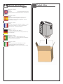
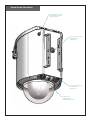
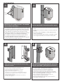
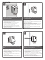
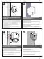
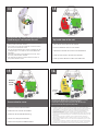
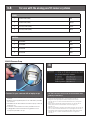
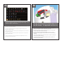
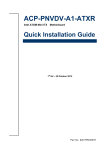
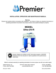
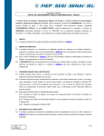
© 2012, Moog Videolarm, Inc. All Rights Reserved
Liberty™ Series
Cellular & WiFi Enabled Camera Enclosure
www.moogvideolarm.com
Installation and Operation Instructions for the following models:
LDW75CLG
Liberty Series wireless IP Ready dome. Include cellular router, power supply
for the complete system. Cellular broadband adapter sold separately. 110/220VAC input. Designed to work with Moog Videolarm IP Ready Series
of IP camera housings
Before attempting to connect or operate this product, please read these instructions completely.
W81-IN5453
08-02-2012
IMPORTANT SAFEGUARDS
1
Read these instructions.
2
Keep these instructions.
3
Heed all warnings
4
Follow all instructions.
5
Do not use this apparatus near water.
6
Clean only with damp cloth.
7
Do not block any of the ventilation openings. Install in accordance with the
SAFETY PRECAUTIONS
CAUTION
RISK OF ELECTRIC SHOCK
DO NOT OPEN
manufacturers instructions.
8
Cable Runs- All cable runs must be within permissible distance.
9
Mounting - This unit must be properly and securely mounted to a supporting
structure capable of sustaining the weight of the unit.
Accordingly:
a. The installation should be made by a qualified installer.
b. The installation should be in compliance with local codes.
c. Care should be exercised to select suitable hardware to install the unit, taking into
account both the composition of the mounting surface and the weight of the
unit.
10 Do not install near any heat sources such as radiators, heat registers, stoves, or other
apparatus ( including amplifiers) that produce heat.
11 Do not defeat the safety purpose of the polarized or grounding-type plug. A
polarized plug has two blades with one wider than the other. A grounding type
plug has two blades and a third grounding prong. The wide blade or the third
prong are provided for your safety. When the provided plug does not fit into your
outlet, consult an electrician for replacement of the obsolete outlet.
12 Protect the power cord from being walked on or pinched particularly at plugs,
convenience receptacles, and the point where they exit from the apparatus.
13 Only use attachment/ accessories specified by the manufacturer.
14 Use only with a cart, stand, tripod, bracket, or table specified by the manufacturer,
or sold with the apparatus. When a cart is used, use caution when moving the cart/
apparatus combination to avoid injury from tip-over.
15 Unplug this apparatus during lighting storms or when unused for long periods of time.
16 Refer all servicing to qualified service personnel. Servicing is required when the
apparatus has been damaged in any way, such as power-supply cord or plug is
damaged, liquid has been spilled of objects have fallen into the apparatus, the
apparatus has been exposed to rain or moisture, does not operate normally, or
has been dropped.
Be sure to periodically examine the unit and the supporting structure to make sure that the
integrity of the installation is intact. Failure to comply with the foregoing could result in the
unit separating from the support structure and falling, with resultant damages or injury to
anyone or anything struck by the falling unit.
UNPACKING
Unpack carefully. Electronic components can be
damaged if improperly handled or dropped. If an item
appears to have been damaged in shipment, replace
it properly in its carton and notify the shipper.
Be sure to save:
1 The shipping carton and packaging material.
They are the safest material in which to make
future shipments of the equipment.
2 These Installation and Operating Instructions.
SERVICE
If technical support or service is needed, contact us
at the following number:
TECHNICAL SUPPORT
AVAILABLE 24 HOURS
1 - 800 - 554 -1124
CAUTION: TO REDUCE THE RISK OF
ELECTRIC SHOCK, DO NOT REMOVE
COVER ( OR BACK). NO USER- SERVICEABLE PARTS INSIDE. REFER SEVICING TO
QUALIFIED SERVICE PERSONNEL.
The lightning flash with an arrowhead
symbol, within an equilateral triangle, is
intended to alert the user to the presence
of non-insulated “dangerous voltage”
within the product’s enclosure that may be
of sufficient magnitude to constitute a risk
to persons.
Este símbolo se piensa para alertar al usuario a la
presencia del “voltaje peligroso no-aisIado” dentro del
recinto de los productos que puede ser un riesgo de
choque eléctrico.
Ce symbole est prévu pour alerter I’utilisateur à la
presence “de la tension dangereuse” non-isolée dans la
clôture de produits qui peut être un risque de choc
électrique.
Dieses Symbol soll den Benutzer zum Vorhandensein der
nicht-lsolier “Gefährdungsspannung” innerhalb der
Produkteinschließung alarmieren die eine Gefahr des
elektrischen Schlages sein kann.
Este símbolo é pretendido alertar o usuário à presença
“di tensão perigosa non-isolada” dentro do cerco dos
produtos que pode ser um risco de choque elétrico.
Questo simbolo è inteso per avvertire I’utente alla
presenza “di tensione pericolosa” non-isolata all’interno
della recinzione dei prodotti che può essere un rischio di
scossa elettrica.
The exclamation point within an equilateral
triangle is intended to alert the user to
presence of important operating and
maintenance (servicing) instructions in the
literature accompanying the appliance.
Este símbolo del punto del exclamation se piensa para
alertar al usuario a la presencia de instrucciones
importantes en la literatura que acompaña la
aplicación.
Ce symbole de point d’exclamation est prévu pour
alerter l’utilisateur à la presence des instructions
importantes dans la littérature accompagnant
l’appareil.
Dieses Ausruf Punktsymbol soll den Benutzer zum
Vorhandensein de wichtigen Anweisungen in der
Literatur alarmieren, die das Gerät begleitet.
Este símbolo do ponto do exclamation é pretendido
alertar o usuário à presença de instruções importantes
na literatura que acompanha o dispositivo.
Questo simbolo del punto del exclamaton è inteso per
avvertire l’utente alla presenza delle istruzioni importanti
nella letteratura che accompagna l'apparecchio.
Limited Warranty for Moog Videolarm Products
Moog Videolarm warrants these products to be free from defects in material or workmanship as follows:
PRODUCT CATEGORY
PARTS \ LABOR
All Enclosures and Electronics*
Five
Poles/PolEvators™/CamEvator
Three (3) Years
Warrior Series™/Q-View™/IR Illuminators
Five
(5) Years
SView Series™
Five
(5) Years **6 months if used in auto scan/tour operation
Controllers
Five
(5) Years
Power Supplies
Five
(5) Years
EcoKit
Three (3) Years
Accessory Brackets
Five
*DeputyDome™, NiteTrac™, Igloo Dome, PurgeDome™
Three (3) Years **6 months if used in auto scan/tour operation
(5) Years
(5) Years
During the labor warranty period, to repair the Product, Purchaser will either return the defective product, freight prepaid, or deliver it to Moog Videolarm
Inc. Decatur GA. The Product to be repaired is to be returned in either its original carton or a similar package affording an equal degree of protection with
a RMA # (Return Materials Authorization number) displayed on the outer box or packing slip. To obtain a RMA# you must contact our Technical Support
Team at 800.554.1124, extension 101. Moog Videolarm will return the repaired Product freight prepaid to Purchaser. Moog Videolarm is not obligated to
provide Purchaser with a substitute unit during the warranty period or at any time. After the applicable warranty period, Purchaser must pay all labor and/or
parts charges.
The limited warranty stated in these product instructions is subject to all of the following terms and conditions.
TERMS AND CONDITIONS
1. NOTIFICATION OF CLAIMS: WARRANTY SERVICE: If Purchaser believes that the Product is defective in material or workmanship, then written notice with an
explanation of the claim shall be given promptly by Purchaser to Moog Videolarm. All claims for warranty service must be made within the warranty period.
If after investigation Moog Videolarm determines the reported problem was not covered by the warranty, Purchaser shall pay Moog Videolarm for the cost of
investigating the problem at its then prevailing per incident billable rate. No repair or replacement of any Product or part thereof shall extend the warranty period
of the entire Product. The specific warranty on the repaired part only shall be in effect for a period of ninety (90) days following the repair or replacement of that
part or the remaining period of the Product parts warranty, whichever is greater.
2. EXCLUSIVE REMEDY: ACCEPTANCE: Purchaser’s exclusive remedy and Moog Videolarm’s sole obligation is to supply (or pay for) all labor necessary to repair any
Product found to be defective within the warranty period and to supply, at no extra charge, new or rebuilt replacements for defective parts.
3. EXCEPTIONS TO LIMITED WARRANTY: Moog Videolarm shall have no liability or obligation to Purchaser with respect to any Product requiring service during the
warranty period which is subjected to any of the following: abuse, improper use, negligence, accident, lightning damage or other acts of God (i.e., hurricanes,
earthquakes), modification, failure of the end-user to follow the directions outlined in the product instructions, failure of the end-user to follow the maintenance
procedures recommended by the International Security Industry Organization, written in product instructions, or recommended in the service manual for the
Product. Furthermore, Moog Videolarm shall have no liability where a schedule is specified for regular replacement or maintenance or cleaning of certain parts
(based on usage) and the end-user has failed to follow such schedule; attempted repair by non-qualified personnel; operation of the Product outside of the
published environmental and electrical parameters, or if such Product’s original identification (trademark, serial number) markings have been defaced, altered,
or removed. Moog Videolarm excludes from warranty coverage Products sold AS IS and/or WITH ALL FAULTS and excludes used Products which have not
been sold by Moog Videolarm to the Purchaser. All software and accompanying documentation furnished with, or as part of the Product is furnished “AS IS”
(i.e., without any warranty of any kind), except where expressly provided otherwise in any documentation or license agreement furnished with the Product. Any
cost associated with removal of defective product and installation of replacement product is not included in this warranty.
4. PROOF OF PURCHASE: The Purchaser’s dated bill of sale must be retained as evidence of the date of purchase and to establish warranty eligibility.
DISCLAIMER OF WARRANTY
EXCEPT FOR THE FOREGOING WARRANTIES, Moog Videolarm HEREBY DISCLAIMS AND EXCLUDES ALL OTHER WARRANTIES, EXPRESS OR IMPLIED,
INCLUDING, BUT NOT LIMITED TO ANY AND/OR ALL IMPLIED WARRANTIES OF MERCHANTABILITY, FITNESS FOR A PARTICULAR PURPOSE AND/OR
ANY WARRANTY WITH REGARD TO ANY CLAIM OF INFRINGEMENT THAT MAY BE PROVIDED IN SECTION 2-312(3) OF THE UNIFORM COMMERCIAL
CODE AND/OR IN ANY OTHER COMPARABLE STATE STATUTE. Moog Videolarm HEREBY DISCLAIMS ANY REPRESENTATIONS OR WARRANTY THAT
THE PRODUCT IS COMPATIBLE WITH ANY COMBINATION OF NON-Moog Videolarm PRODUCTS OR NON-Moog Videolarm RECOMMENDED PRODUCTS
PURCHASER MAY CHOOSE TO CONNECT TO THE PRODUCT.
LIMITATION OF LIABILITY
THE LIABILITY OF Moog Videolarm, IF ANY, AND PURCHASER’S SOLE AND EXCLUSIVE REMEDY FOR DAMAGES FOR ANY CLAIM OF ANY KIND
WHATSOEVER, REGARDLESS OF THE LEGAL THEORY AND WHETHER ARISING IN TORT OR CONTRACT, SHALL NOT BE GREATER THAN THE ACTUAL
PURCHASE PRICE OF THE PRODUCT WITH RESPECT TO WHICH SUCH CLAIM IS MADE. IN NO EVENT SHALL Moog Videolarm BE LIABLE TO PURCHASER
FOR ANY SPECIAL, INDIRECT, INCIDENTAL, OR CONSEQUENTIAL DAMAGES OF ANY KIND INCLUDING, BUT NOT LIMITED TO, COMPENSATION,
REIMBURSEMENT OR DAMAGES ON ACCOUNT OF THE LOSS OF PRESENT OR PROSPECTIVE PROFITS OR FOR ANY OTHER REASON WHATSOEVER.
!
Electrical Specifications
LDW75CLG
120/240 VAC 50/60Hrz.
96 Watts
Accessories:
Heater: 50 Watts, Blower: 2 Watt
Camera Power: (See Camera Specifications): 40 Watts Max
English
Español
120/240VAC 50/60Hrz.
96 Vatios
De Accesorios: Calentador: 50 Watts, Blower: 2 Vatio
Energía De la Cámara fotográfica De : (Véase Las
Especificaciones De la Cámara fotográfica): 40 Vatios
De Herramientas Máximas
120/240VCA 50/60Hrz.
96 Watts
D'Accessoires : Réchauffeur : 50 Watts, Ventilateur : 2 watts.
Puissance D'Appareil-photo : (Voir Les Caractéristiques
D'Appareil-photo) : 40 Watts De Maximum
Français
120/240VAC 50/60Hrz.
96 Watt
Zusatzgerät-: Heizung: 50 Watts, Blower: 2
Watt-Kamera-Energie: (Sehen Sie Kamera-Spezifikationen):
40 Watt Maximale
Deutsch
120/240VAC 50/60Hrz.
96 Watts
De Acessórios: Calefator: 50 Watts, Blower: 2 Watt
Poder Da Câmera De : (Veja Especificações Da Câmera):
40 Watts De Ferramentas Máximas
Portuguese
Italiano
120/240VCA 50/60Hrz.
96 Watt
Di Accessori: Riscaldatore: 50 Watts, Blower: 2 Watt
Alimentazione Della Macchina fotografica Da :
(Veda Le Specifiche Della Macchina fotografica): 40 Watt
Di Attrezzi Massimi
Content of Box
Power Feed Locations:
LIQUID TIGHT PLUG FOR
3G ANTENNA BULKHEAD
CONNECTOR HOLE.
LIQUID TIGHT PLUG FOR
OPTIONAL MAIN
POWER HOLE.
LIQUID TIGHT PLUG FOR
OPTIONAL MAIN
POWER HOLE.
LIQUID TIGHT
STRAIN RELIEF
FOR MAIN POWER HOLE.
POLE MOUNTING
1
2
Holes for
steel straps
LDW75CLG unit is ready to mount. Use marked
holes to attach steel straps.
• La unidad de LDW75CLG está lista para montar. Utilice
los agujeros marcados para atar las correas de acero.
• L'unité de LDW75CLG est prête à monter. Employez les
trous marqués pour attacher les courroies en acier.
• LDW75CLG Maßeinheit ist bereit anzubringen. Benutzen
Sie markierte Löcher, um Stahlbügel anzubringen.
• A unidade de LDW75CLG está pronta para montar.
Use furos marcados para unir as cintas de aço.
• L'unità di LDW75CLG è pronta a montare. Usi i profondi
fori per attaccare le cinghie d'acciaio.
3
Use the steel straps to mount the unit to a pole.
• Utilice las correas de acero para montar la unidad al
poste.
• Employez les courroies en acier pour monter l'unité au
poteau.
• Benutzen Sie die Stahlbügel, um die Maßeinheit zum
Pfosten anzubringen.
• Use as cintas de aço para montar a unidade ao pólo.
• Usi le cinghie d'acciaio per montare l'unità al palo.
4
Attach pole mount clips to bracket as shown, using
hardware provided.
Place the housing onto the bracket, secure by
using the provided 2 (M10) bolts and washers.
•
Ate los clips del montaje del poste para acorchetar como
se muestra, usando el hardware proporcionado.
•
Attachez les agrafes de bâti de poteau à la parenthèse
comme montré, utilisant le matériel fourni.
•
Bringen Sie Pfosteneinfassungsclips an, um wie gezeigt
einzuklammern, unter Verwendung der bereitgestellten Hardware.
•
Una grampos da montagem do pólo ao suporte como mostrado,
usando a ferragem fornecida.
•
Attacchi le clip del supporto del palo alla staffa come indicato,
per mezzo dei fissaggi forniti.
• Coloque la cubierta sobre el soporte, seguro usando
los 2 pernos (M10) y arandelas proporcionados.
• Placez le logement sur la parenthèse, bloquée en
employant les 2 boulons (M10) et rondelles fournis.
• Setzen Sie das Gehäuse auf dem Haltewinkel, der indem
Sie die zur Verfügung gestellten 2 sicher ist, Schraubbolzen
(M10) und die Unterlegscheiben verwenden.
• Coloc a carcaça no suporte, seguro usando os 2
parafusos (M10) e arruelas fornecidos.
• Disponga l'alloggiamento sulla staffa, sicura usando i 2
bulloni (M10) e rondelle forniti.
WALL MOUNTING
5
Affix the wall mount bracket to the surface
of the wall as shown.
• Ponga el soporte del montaje de la pared a la
superficie de la pared como se muestra.
• Apposez la parenthèse de bâti de mur sur la surface
du mur comme montrée.
• Fügen Sie den Wandeinfassungshaltewinkel zur
Oberfläche der Wand wie gezeigt hinzu.
• Afixe o suporte da montagem da parede à superfície
da parede como mostrada.
• Affiggi la staffa del supporto della parete alla superficie
della parete come indicata.
7
6
Tilt the unit to align the grooves (holes) to the
lips on the bracket.
• Incline la unidad para alinear los surcos (agujeros) con
los labios en el soporte.
• Inclinez l'unité pour aligner les cannelures (trous) sur les
lèvres sur la parenthèse.
• Kippen Sie die Maßeinheit, um die Nuten (Löcher) mit
den Lippen am Haltewinkel auszurichten.
• Incline a unidade para alinhar os sulcos (furos) aos
bordos no suporte.
• Inclini l'unità per allineare le scanalature (fori) alle
labbra sulla staffa.
8
Bolts/Washers
Slide the tilted unit over the lips to lock it into
place.
Shows the wall mount option of hanging unit
and where to secure the bolt.
• Deslice la unidad inclinada sobre los labios para
trabarla en lugar.
• Glissez l'unité inclinée au-dessus des lèvres pour la
fermer à clef sur l'endroit.
• Schieben Sie die gekippte Maßeinheit über den Lippen,
um sie in Platz zu verriegeln.
• Deslize a unidade inclinada sobre os bordos para
travá-la no lugar.
• Faccia scorrere l'unità inclinata sopra le labbra per
chiuderlo a chiave nel posto.
• Demuestra la opción del montaje de la pared de la
unidad colgante y donde asegurar el perno.
• Montre l'option de bâti de mur de l'unité accrochante
et où fixer le boulon.
• Zeigt die Wandeinfassungswahl der hängenden
Maßeinheit und wo man den Schraubbolzen sichert.
• Mostra a opção da montagem da parede da unidade
de suspensão e onde fixar o parafuso.
• Mostra l'opzione del supporto della parete dell'unità
d'attaccatura e dove assicurare il bullone.
9
To install a camera or for the maintenance of the
unit (if needed) you should flip so that the dome is
facing upwards.
•
•
•
•
•
Para instalar una cámara o para el mantenimiento de la unidad (si es
necesario) que usted debe mover de un tirón de modo que la bóveda
esté haciendo frente hacia arriba.
Pour installer un appareil-photo ou pour l'entretien de l'unité (si nécessaire)
que vous devriez renverser de sorte que le dôme fasse face vers le haut.
Zu eine Kamera oder für die Wartung der Maßeinheit anbringen
(wenn erforderlich), das Sie leicht schlagen sollten, damit die
Haube aufwärts gegenüberstellt.
Para instalar uma câmera ou para a manutenção da unidade
(se necessário) que você deve lanç de modo que a abóbada
esteja enfrentando para cima.
Per per installare una macchina fotografica o per il mantenimento
dell'unità (se necessario) che dovreste lanciare in modo che la cupola
stia affrontando verso l'alto.
11
10
Remove the dome and follow the specified
camera mounting options.
• Quite la bóveda y siga las opciones especificadas del
montaje de la cámara.
• Enlevez le dôme et suivez les options spécifiques de
support d'appareil-photo.
• Entfernen Sie die Haube und folgen Sie den spezifizierten Kameramontagewahlen.
• Remova a abóbada e siga as opções especific da
montagem da câmera.
• Rimuova la cupola e segua le opzioni specificate del
montaggio della macchina fotografica.
12
Bolts /washers
Complete the necessary electrical wiring. Use the provided
bolts and washers to secure the housing in place.
• Termine el cableado eléctrico necesario. Utilice los pernos y las
arandelas proporcionados para asegurar la cubierta en el lugar.
• Accomplissez le câblage électrique nécessaire. Employez les boulons
et les rondelles fournis pour fixer le logement en place.
• Schließen Sie die notwendige elektrische Verdrahtung ab. Benutzen Sie
die zur Verfügung gestellten Schraubbolzen und die Unterlegscheiben,
um das Gehäuse an der richtigen Stelle zu sichern.
• Termine a fiação elétrica necessária. Use os parafusos e as arruelas
fornecidos para fixar a carcaça no lugar.
• Completi i collegamenti elettrici necessari. Usi i bulloni e le rondelle
forniti per fissare l'alloggiamento sul posto.
Shows the unit mounted to the wall.
• Demuestra la unidad montada a la pared.
• Montre l'unité montée au mur.
• Zeigt die Maßeinheit, die zur Wand angebracht wird.
• Mostra a unidade montada à parede.
• Mostra l'unità montata alla parete.
14
13
To open the top cover unlock the latches.
From here you can activate the unit
Top inside view of the unit.
• Para abrir la cubierta superior abra los cierres. Aquí de
usted puede activar la unidad.
• Pour ouvrir la couverture supérieure ouvrez les verrous.
D'ici vous pouvez activer l'unité.
• Um die obere Abdeckung zu öffnen entriegeln Sie die
Verriegelungen. Von hier Ihnen kann die Maßeinheit
aktivieren.
• Para abrir a tampa superior destrave as travas. Aqui
de você pode ativar a unidade.
• Per aprire la copertura superiore sblocchi i fermi. Di
qui potete attivare l'unità.
• Dessus à l'intérieur de la vue de l'unité.
• Oberseite innerhalb der Ansicht der Maßeinheit.
• Parte superior dentro da ideia da unidade.
• Parte superiore all'interno della vista dell'unità.
16
L
N
15
• Tapa dentro de la vista de la unidad.
Remove
barrier
cover
120/240VAC
Aux. output
24VAC
Aux. output
Remove barrier cover.
• Quite la cubierta de la barrera.
1.
2.
3.
4.
Move the 115//240VAC selector switch (3) to the desired position
Insure that the ON/OFF switch (2) is in the off position
Attach the in coming “main” power to the 120/240 VAC input
Move the ON/OFF switch (2) to the ON position.
•
1. Mueva el interruptor de selector 115//240VAC (3) a la posición deseada 2. Asegure que el
interruptor CON./DESC. (2) está en la posición de reposo 3. Ate en energía “principal” que viene a
la entrada de 120/240 VAC 4. Mueva el interruptor CON./DESC. (2) a la posición de trabajo.
1. Déplacez le sélecteur 115//240VAC (3) à la position désirée 2. Assurez-vous que le commutateur
"MARCHE/ARRÊT" (2) est dans la position de repos 3. Attachez dans la prochaine puissance «
principale » à l'entrée de 120/240 VCA 4. Déplacez le commutateur "MARCHE/ARRÊT" (2) à la
position de fonctionnement.
1. Verschieben Sie den Schalter des Wähl 115//240VAC (3) auf die gewünschte Position 2.
Versichern Sie, dass der Ein/Aus-Schalter (2) in der Ausschaltstellung ist 3. Bringen Sie in kommender
„Haupt“ Energie zum 120/240 VAC-Eingang an 4. Verschieben Sie den Ein/Aus-Schalter (2) auf die
Arbeitsstellung.
1. Mova o interruptor de seletor 115//240VAC (3) para a posição desejada 2. Segure que o
interruptor DE LIGAR/DESLIGAR (2) está no posição de repouso 3. Una no poder “principal” de
vinda à entrada de 120/240 de VAC 4. Mova o interruptor DE LIGAR/DESLIGAR (2) para o posição
de functionamento.
1. Sposti l'interruttore di selettore 115//240VAC (3) alla posizione voluta 2. Assicuri che l'interruttore
acceso/spento (2) è nella posizione di riposo 3. Attacchi nel potere “principale„ venente all'input
da 120/240 di VCA 4. Sposti l'interruttore acceso/spento (2) alla posizione di funzionamento.
•
• Enlevez la couverture de barrière.
•
• Entfernen Sie Sperrenabdeckung.
• Remova a tampa da barreira.
• Rimuova la copertura della barriera.
•
•
16B
For use with the analog pan/tilt camera systems
POWER
1
Camera Power (24Vac)
Red
2
Camera Power (24Vac)
Orange
3
Accessory Power (24Vac)
Yellow
4
Accessory Power (24Vac)
Green
1
RS-485RXA
Blue
2
RS-485RXB
Violet
3
RS-485TXA
Gray
4
RS-485TXB
White
CONTROL
3G/4G Camera Prep
17
18
Assign your camera the static TCP/IP address of
192.168.1.50 with a subnet mask of 255.255.255.0 and a
gateway of 192.168.1.1.
Connect to your camera with a laptop or pc
• Conecte con su cámara con un ordenador portátil o
una PC.
• Reliez à votre appareil-photo à un ordinateur portable
ou à un PC.
• Schließen Sie an Ihre Kamera an einen Laptop oder an
einen PC an.
• Conecte a sua câmera com um portátil ou um PC.
• Colleghi alla vostra macchina fotografica con un
computer portatile o un pc.
•
•
•
•
•
Asigne a su cámara la dirección estática del TCP/IP de 192.168.1.50 con
un subnet mask de 255.255.255.0 y una entrada de 192.168.1.1.
Assignez à votre appareil-photo l'adresse statique de TCP/IP de
192.168.1.50 avec un subnet mask de 255.255.255.0 et un passage de
192.168.1.1.
Weisen Sie Ihrer Kamera die statische IP-Adresse von 192.168.1.50 mit
einem subnet mask von 255.255.255.0 und einem Zugang von
192.168.1.1 zu.
Atribua a sua câmera o endereço de estática do TCP/IP de 192.168.1.50
com um subnet mask de 255.255.255.0 e uma passagem de 192.168.1.1.
Assegni alla vostra macchina fotografica l'indirizzo statico del TCP/IP di
192.168.1.50 con un subnet mask di 255.255.255.0 e un ingresso di
192.168.1.1.
USB 3G/4G Card Prep
19
Change to HTTP port from the default port 80 to
the port 12345.
• Cambie al puerto del HTTP del puerto 80 del defecto al puerto 12345.
• Changez en le port de HTTP du port 80 de défaut en port 12345.
• Ändern Sie zum HTTP-Hafen vom Rückstellungshafen 80 zum Hafen
12345.
• Mude ao porto do HTTP do porto 80 do defeito ao porto 12345.
• Cambi all'orificio del HTTP dall'orificio 80 di difetto all'orificio 12345.
20
When ordering your service with your provider, have
them add a static ip address to the service <extra
charge may be involved>
• Al pedir su servicio con su abastecedor, haga que agreguen un IP
address estático al servicio (el recargo puede estar implicado).
• En commandant votre service avec votre fournisseur, faites-ajouter les
un IP address statique au service (le supplément peut être impliqué).
• Wenn Sie Ihren Service mit Ihrem Versorger bestellen, lassen Sie sie ein
statisches IP address dem Service hinzufügen (Extragebühr kann
beteiligt sein) .
• Ao requisitar seu serviço com seu fornecedor, mande-os adicionar um
IP address de estática ao serviço (a sobretaxa pode ser involvida.
• Nell'ordinare il vostro servizio con il vostro fornitore, facciali aggiungere
un IP address statico al servizio (la carica supplementare può essere
implicata).
21
Some users may require WiFi access to the unit as well. Connect to the WiFi
network by selecting the SSID that contains the word Videolarm and a
combination of three letters and numbers. An example is Videolarm2A0 as
shown above. The encryption key for the network is password.
•
•
•
•
•
Algunos usuarios pueden requerir el acceso de WiFi a la unidad también. Conecte con la red de
WiFi seleccionando el SSID que contiene la palabra Videolarm y una combinación de tres letras y
números. Un ejemplo es Videolarm2A0 como se muestra arriba. La llave de encripción para la red
es contraseña.
Quelques utilisateurs peuvent avoir besoin de l'accès de WiFi à l'unité aussi bien. Reliez au réseau de
WiFi en choisissant le SSID qui contient le mot Videolarm et une combinaison de trois lettres et
nombres. Un exemple est Videolarm2A0 comme montré ci-dessus. La clef de chiffrage pour le
réseau est mot de passe.
Einige Benutzer können WiFi Zugang zur Maßeinheit außerdem fordern. Schließen Sie an das WiFi
Netz an, indem Sie das SSID vorwählen, das das Wort Videolarm und eine Kombination von drei
Buchstaben und von Zahlen enthält. Ein Beispiel ist Videolarm2A0 wie gezeigt oben. Der
Verschlüsselungschlüssel für das Netz ist Kennwort.
Alguns usuários podem exigir o acesso de WiFi à unidade também. Conecte à rede de WiFi
selecionando o SSID que contem a palavra Videolarm e uma combinação de três letras e
números. Um exemplo é Videolarm2A0 como mostrado acima. A chave de cifragem para a rede
é senha.
Alcuni utenti possono richiedere l'accesso di WiFi all'unità pure. Colleghi alla rete di WiFi
selezionando lo SSID che contiene la parola Videolarm e una combinazione di tre lettere e numeri.
Un esempio è Videolarm2A0 come indicato sopra. La chiave di crittografia per la rete è parola
d'accesso.
22
Connecting to the WiFI network allows a connection to the admin interface
on the address http://192.168.1.1 as well as local access to the camera on
address http://192.168.1.50:12345. The username for the admin interace is
root with a password of admin.
•
La conexión con la red de WiFI permite una conexión al interfaz del admin en la dirección
http://192.168.1.1 así como el acceso local a la cámara en la dirección http://192.168.1.50:12345.
El username para el interace del admin es raíz con una contraseña del admin.
•
Se relier au réseau de WiFI permet un raccordement à l'interface d'admin sur l'adresse
http://192.168.1.1 aussi bien que l'accès local à l'appareil-photo sur l'adresse
http://192.168.1.50:12345. L'username pour l'interace d'admin est racine avec un mot de passe
d'admin.
•
Die Verbindung an das WiFI Netz erlaubt einen Anschluss zur admin-Schnittstelle auf der Adresse
http://192.168.1.1 sowie lokalen Zugang zur Kamera auf Adresse http://192.168.1.50:12345. Das
username für das admin interace ist Wurzel mit einem Kennwort von admin.
•
Conectar à rede de WiFI permite uma conexão à relação do admin no endereço
http://192.168.1.1 assim como o acesso local à câmera no endereço http://192.168.1.50:12345. O
username para o interace do admin é raiz com uma senha do admin.
•
Collegandosi alla rete di WiFI permette un collegamento all'interfaccia di admin sull'indirizzo
http://192.168.1.1 così come accesso locale alla macchina fotografica sull'indirizzo
http://192.168.1.50:12345. Il username per il interace di admin è radice con una parola d'accesso
del admin.
23
Advanced configuration options for changing the WiFI settings, etc. are
available through the admin interface.
24
Use the provided velcro to mount and secure
the USB modem. On applicable models only.
•
Las opciones de configuración avanzadas para cambiar los ajustes de WiFI, el etc. están
disponibles a través del interfaz del admin.
•
Les options de configuration avancées pour changer les arrangements de WiFI, etc. sont
disponibles par l'interface d'admin.
•
Vorgerückte Konfigurationswahlen für das Ändern der WiFI Einstellungen, des etc. sind durch die
admin-Schnittstelle vorhanden.
•
As opções de configuração avançadas para mudar os ajustes de WiFI, etc. estão disponíveis
através da relação do admin.
• Benutzen Sie den zur Verfügung gestellten Flausch, um das
USB-Modem anzubringen und zu sichern. Auf nur anwendbaren
Modellen.
•
Le opzioni di configurazione avanzate per il cambiamento le regolazioni di WiFI, ecc. sono
disponibili attraverso l'interfaccia di admin.
• Use o velcro fornecido para montar e fixar o modem do USB. Em
modelos aplicáveis somente.
• Utilice el velcro proporcionado para montar y para asegurar el
módem del USB. En modelos aplicables solamente.
• Employez le Velcro fourni pour monter et fixer le modem d'USB.
Sur les modèles applicables seulement.
• Usi il velcro fornito per montare e fissare il modem del USB. Sui
modelli applicabili soltanto.
Replacement Parts
LDW75CLG
Liberty Series
PART #
DESCRIPTION
1 RP40VL3707
2 RPLBHNG
3 RP30VL3708
4 RP96GK3710
5 RP70VL3727
6 RP76VL2007
7 RP96SJ355012
8 RP70TRANS12
9 RP30VL3712
10 RP76RCNEX1
11 RP30VL3701
12 RP30VL2742
13 RP954GLTCH
14 RP71VLBL03
15 RP70LF3VR3
16 RP70SPPA405
17 RP40BR3510
18 RP25DCR73000
1
2
3
4
TOP COVER ASSEMBLY
TOP COVER HINGES, LEFT&RIGHT
HINGE PLATE
TOP COVER GASKET
BOARD SHIELD
4G POWER & CONNECTION BOARD ASSEMBLY
1/2" BLACK DUAL LOCK FASTENER WITH VHB TAPE
REPLACEMENT TRANSFORMER 96 VA
ANTENNA BRACKET
NEXTARA MOBLE ROUTING BOARD
WALL MOUNT BRACKET
POLE MOUNT CLIPS
LATCHE SIERRA 210-120SS
FUSION DOME BLOWER 40X40X10MM, 1.0 WATT, ROHS
120/240V 50-60Hz LINE FILTER
15A PARALLEL SURGE PROTECTOR
FD7 MAIN CAMERA BRACKET ASSEMBLY
CLEAR DOME, WHITE TRIMRING, R7 STYLE
5
6
7
8
9
10
11
12
13
14
15
16
17
18
Product Registration/Warranty
Thank you for choosing Moog Videolarm. We value your patronage and are solely committed to providing you with the highest
quality products available and superior customer service.
Should a problem arise, rest assured that Moog Videolarm stands behind its products by offering impressive 3 Year and 5 Year warranties, depending on the product
purchased. See full warranty details at www.moogvideolarm.com/technical-support/warranty-plan/
Register Your Products Online
Please take a few moments to register your purchase via the Online Product Registration Form at:
www.moogvideolarm.com/technical-support/product-registration
Register your recent Moog Videolarm purchase and benefit from the following:
• Simple and Trouble-Free RMA process
• Receive product updates, and special promotion
• Eliminate the need to archive original purchase documents:
Receipts, Purchase Orders, etc…