1
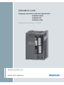
SINAMICS G120
Frequency converters with the Control Units
CU230P-2 HVAC
CU230P-2 DP
CU230P-2 CAN
Operating instructions · 01 2011
SINAMICS
Answers for industry.
Frequency inverters with Control Units ___________________
Change history
CU230P-2 HVAC,
SINAMICS
SINAMICS G120
Frequency inverters with Control
Units CU230P-2 HVAC, CU230P-2
DP, CU230P-2 CAN
Operating Instructions
1
___________________
Introduction
2
___________________
Description
___________________
3
Installing
4
___________________
Commissioning
5
___________________
Adapting the terminal strip
___________________
6
Configuring the fieldbus
___________________
7
Functions
___________________
8
Service and maintenance
Alarms, faults and system
___________________
9
messages
___________________
10
Technical data
___________________
A
Appendix
Edition 01/2011, Firmware V4.4
Original instructions
01/2011, FW 4.4
A5E02430659B AD
Legal information
Legal information
Warning notice system
This manual contains notices you have to observe in order to ensure your personal safety, as well as to prevent
damage to property. The notices referring to your personal safety are highlighted in the manual by a safety alert
symbol, notices referring only to property damage have no safety alert symbol. These notices shown below are
graded according to the degree of danger.
DANGER
indicates that death or severe personal injury will result if proper precautions are not taken.
WARNING
indicates that death or severe personal injury may result if proper precautions are not taken.
CAUTION
with a safety alert symbol, indicates that minor personal injury can result if proper precautions are not taken.
CAUTION
without a safety alert symbol, indicates that property damage can result if proper precautions are not taken.
NOTICE
indicates that an unintended result or situation can occur if the corresponding information is not taken into
account.
If more than one degree of danger is present, the warning notice representing the highest degree of danger will
be used. A notice warning of injury to persons with a safety alert symbol may also include a warning relating to
property damage.
Qualified Personnel
The product/system described in this documentation may be operated only by personnel qualified for the specific
task in accordance with the relevant documentation for the specific task, in particular its warning notices and
safety instructions. Qualified personnel are those who, based on their training and experience, are capable of
identifying risks and avoiding potential hazards when working with these products/systems.
Proper use of Siemens products
Note the following:
WARNING
Siemens products may only be used for the applications described in the catalog and in the relevant technical
documentation. If products and components from other manufacturers are used, these must be recommended
or approved by Siemens. Proper transport, storage, installation, assembly, commissioning, operation and
maintenance are required to ensure that the products operate safely and without any problems. The permissible
ambient conditions must be adhered to. The information in the relevant documentation must be observed.
Trademarks
All names identified by ® are registered trademarks of the Siemens AG. The remaining trademarks in this
publication may be trademarks whose use by third parties for their own purposes could violate the rights of the
owner.
Disclaimer of Liability
We have reviewed the contents of this publication to ensure consistency with the hardware and software
described. Since variance cannot be precluded entirely, we cannot guarantee full consistency. However, the
information in this publication is reviewed regularly and any necessary corrections are included in subsequent
editions.
Siemens AG
Industry Sector
Postfach 48 48
90026 NÜRNBERG
GERMANY
A5E02430659B AD
Ⓟ 04/2011
Copyright © Siemens AG 2009,
2010, 2011.
Technical data subject to change
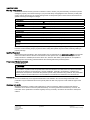
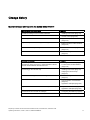
Change history
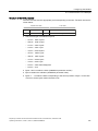
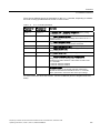
Important changes with respect to the manual Edition 07/2010
New functions in firmware V4.4
In Chapter
Predefined settings for the converter interfaces
•
Installing Control Unit (Page 44)
Two- and three-wire control via terminal block
•
Inverter control (Page 185)
Unit changeover
•
Application-specific functions
(Page 219)
Expanded options for controlling DC braking
•
Braking functions of the converter
(Page 225)
Automatic restart expanded by a new mode
•
Automatic restart and flying restart
(Page 237)
Trace via STARTER
•
Commissioning with STARTER
(Page 68)
Revised descriptions
In Chapter
The description of the PM240-2 and PM250-2 Power
Modules has been removed. It is expected that this Power
Module will be released with firmware V4.5.
•
Installing Power Module (Page 30)
•
Technical data, Power Modules
(Page 305)
Connecting up the terminal strip
•
Installing Control Unit (Page 44)
•
Adapting the terminal strip
(Page 85)
USB interface settings for commissioning with STARTER.
•
Commissioning with STARTER
(Page 68)
Slave-to-slave communication via PROFIBUS DP
•
Communication via PROFIBUS
(Page 98)
•
Application examples (Page 323)
•
Acyclic communication (Page 113)
•
Application examples (Page 323)
Connection of the converter to CANopen
•
Configuring the fieldbus (Page 97)
Function overview
•
Functions (Page 183)
Acyclic communication via PROFIBUS DP (data set 47)
Frequency inverters with Control Units CU230P-2 HVAC, CU230P-2 DP, CU230P-2 CAN
Operating Instructions, 01/2011, FW 4.4, A5E02430659B AD
3
Change history
Frequency inverters with Control Units CU230P-2 HVAC, CU230P-2 DP, CU230P-2 CAN
4
Operating Instructions, 01/2011, FW 4.4, A5E02430659B AD
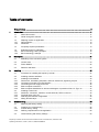
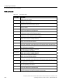
Table of contents
Change history .......................................................................................................................................... 3
1
2
3
4
Introduction.............................................................................................................................................. 11
1.1
About this manual ........................................................................................................................11
1.2
Guide through this manual...........................................................................................................12
1.3
1.3.1
1.3.2
Adapting inverter to application....................................................................................................13
General basics .............................................................................................................................13
Parameter ....................................................................................................................................13
1.4
Frequently required parameters...................................................................................................14
1.5
1.5.1
1.5.2
Extended scope for adaptation ....................................................................................................16
BICO technology: basic principles ...............................................................................................16
BICO technology: example ..........................................................................................................18
Description............................................................................................................................................... 21
2.1
Modularity of the converter system ..............................................................................................21
2.2
Control Units ................................................................................................................................24
2.3
Power Module ..............................................................................................................................25
2.4
Reactors and filters ......................................................................................................................26
Installing .................................................................................................................................................. 27
3.1
Procedure for installing the frequency inverter ............................................................................27
3.2
Installing reactors and filters ........................................................................................................28
3.3
3.3.1
3.3.2
3.3.3
3.3.4
3.3.5
Installing Power Module...............................................................................................................30
Dimensions, hole drilling templates, minimum clearances, tightening torques ...........................31
Connection overview for Power Modules ....................................................................................35
Connecting the line supply and motor .........................................................................................36
EMC-compliant connection ..........................................................................................................39
EMC-compliant installation for devices with degree of protection IP55 / UL Type 12 .................42
3.4
3.4.1
3.4.2
3.4.3
3.4.4
Installing Control Unit...................................................................................................................44
Interfaces, connectors, switches, control terminals, LEDs on the CU .........................................46
Terminal strips of the CU .............................................................................................................47
Selecting the interface assignments ............................................................................................48
Wiring terminal strips ...................................................................................................................51
Commissioning ........................................................................................................................................ 53
4.1
Restoring the factory setting ........................................................................................................55
4.2
4.2.1
4.2.2
Preparing for commissioning .......................................................................................................56
Inverter factory setting .................................................................................................................58
Defining requirements for the application ....................................................................................59
4.3
Commissioning with factory settings............................................................................................60
Frequency inverters with Control Units CU230P-2 HVAC, CU230P-2 DP, CU230P-2 CAN
Operating Instructions, 01/2011, FW 4.4, A5E02430659B AD
5
Table of contents
5
6
4.3.1
Wiring examples for the factory settings ..................................................................................... 61
4.4
4.4.1
4.4.2
4.4.3
4.4.4
Commissioning with the BOP-2 .................................................................................................. 63
Menu structure ............................................................................................................................ 64
Freely selecting and changing parameters ................................................................................. 65
Basic commissioning................................................................................................................... 66
Additional settings ....................................................................................................................... 67
4.5
4.5.1
4.5.2
4.5.3
4.5.4
4.5.5
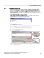
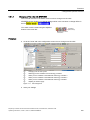
Commissioning with STARTER .................................................................................................. 68
Adapting the USB interface......................................................................................................... 69
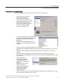
Generating a STARTER project.................................................................................................. 70
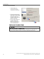
Go online and perform the basic commissioning ........................................................................ 70
Making additional settings........................................................................................................... 74
Trace function for optimizing the drive ........................................................................................ 75
4.6
4.6.1
4.6.1.1
4.6.1.2
4.6.1.3
4.6.2
4.6.3
4.6.4
Data backup and standard commissioning ................................................................................. 78
Backing up and transferring settings using a memory card........................................................ 79
Saving setting on memory card .................................................................................................. 79
Transferring the setting from the memory card........................................................................... 81
Safely remove the memory card ................................................................................................. 82
Backing up and transferring settings using STARTER ............................................................... 83
Saving settings and transferring them using an operator panel ................................................. 83
Other ways to back up settings ................................................................................................... 83
Adapting the terminal strip ....................................................................................................................... 85
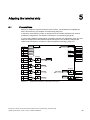
5.1
Preconditions .............................................................................................................................. 85
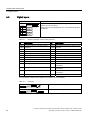
5.2
Digital inputs................................................................................................................................ 86
5.3
Digital outputs ............................................................................................................................. 88
5.4
Analog inputs .............................................................................................................................. 89
5.5
Analog outputs ............................................................................................................................ 93
Configuring the fieldbus ........................................................................................................................... 97
6.1
6.1.1
6.1.2
6.1.3
6.1.4
6.1.4.1
6.1.4.2
6.1.4.3
6.1.4.4
6.1.5
6.1.5.1
Communication via PROFIBUS .................................................................................................. 98
Configuring communication to the control................................................................................... 98
Setting the address ..................................................................................................................... 99
Basic settings for communication ............................................................................................. 100
Cyclic communication ............................................................................................................... 101
Control and status word 1 ......................................................................................................... 102
Control and status word 3 ......................................................................................................... 105
Data structure of the parameter channel .................................................................................. 107
Slave-to-slave communication .................................................................................................. 112
Acyclic communication.............................................................................................................. 113
Reading and changing parameters via data set 47 .................................................................. 113
6.2
6.2.1
6.2.2
6.2.2.1
6.2.2.2
6.2.2.3
6.2.2.4
6.2.2.5
Communication via RS485........................................................................................................ 118
Integrating inverters into a bus system via the RS485 interface............................................... 118
Communication via USS ........................................................................................................... 119
Setting the address ................................................................................................................... 119
Basic settings for communication ............................................................................................. 120
Structure of a USS telegram ..................................................................................................... 120
User data range of the USS telegram....................................................................................... 122
Data structure of the USS parameter channel .......................................................................... 123
Frequency inverters with Control Units CU230P-2 HVAC, CU230P-2 DP, CU230P-2 CAN
6
Operating Instructions, 01/2011, FW 4.4, A5E02430659B AD
Table of contents
7
6.2.2.6
6.2.2.7
6.2.2.8
6.2.2.9
6.2.3
6.2.3.1
6.2.3.2
6.2.3.3
6.2.3.4
6.2.3.5
6.2.3.6
6.2.4
6.2.4.1
6.2.4.2
6.2.4.3
USS read request ......................................................................................................................128
USS write job .............................................................................................................................129
USS process data channel (PZD)..............................................................................................130
Time-out and other errors ..........................................................................................................130
Communication over Modbus RTU............................................................................................133
Setting the address ....................................................................................................................134
Basic settings for communication ..............................................................................................134
Modbus RTU telegram...............................................................................................................135
Baud rates and mapping tables .................................................................................................136
Write and read access via FC 3 and FC 6.................................................................................139
Communication procedure.........................................................................................................141
Communication via BACnet MS/TP ...........................................................................................143
Setting the address ....................................................................................................................144
Basic settings for communication ..............................................................................................144
Supported services and objects.................................................................................................145
6.3
6.3.1
6.3.2
6.3.2.1
6.3.2.2
6.3.2.3
6.3.2.4
6.3.2.5
6.3.2.6
6.3.2.7
6.3.3
6.3.3.1
6.3.4
6.3.4.1
6.3.4.2
6.3.5
Communication over CANopen .................................................................................................152
CANopen functionality of the converter .....................................................................................153
Commissioning CANopen..........................................................................................................154
Setting the node ID and baud rate.............................................................................................154
Monitoring the communication and response of the inverter.....................................................155
SDO services .............................................................................................................................156
Access to SINAMICS parameters via SDO ...............................................................................159
PDO and PDO services .............................................................................................................161
Predefined connection set .........................................................................................................165
Free PDO mapping ....................................................................................................................166
Other CANopen functions ..........................................................................................................167
Network management (NMT service) ........................................................................................167
Object directories .......................................................................................................................170
Free objects ...............................................................................................................................177
Objects in drive profile DSP402 .................................................................................................178
Configuration example ...............................................................................................................179
Functions ............................................................................................................................................... 183
7.1
Overview of the inverter functions..............................................................................................183
7.2
7.2.1
7.2.2
7.2.3
7.2.4
7.2.5
7.2.6
Inverter control ...........................................................................................................................185
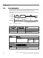
Two-wire control: method 1........................................................................................................186
Two-wire control, method 2........................................................................................................187
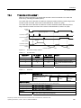
Two-wire control, method 3........................................................................................................188
Three-wire control, method 1 .....................................................................................................189
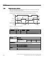
Three-wire control, method 2 .....................................................................................................190
Switching over the inverter control (command data set) ...........................................................191
7.3
Command sources.....................................................................................................................194
7.4
7.4.1
7.4.2
7.4.3
7.4.4
7.4.5
Setpoint sources ........................................................................................................................195
Analog input as setpoint source.................................................................................................195
Motorized potentiometer as setpoint source..............................................................................196
Fixed speed as setpoint source .................................................................................................198
Running the motor in jog mode (JOG function) .........................................................................200
Specifying the motor speed via the fieldbus ..............................................................................201
7.5
7.5.1
Setpoint calculation....................................................................................................................202
Minimum speed and maximum speed .......................................................................................202
Frequency inverters with Control Units CU230P-2 HVAC, CU230P-2 DP, CU230P-2 CAN
Operating Instructions, 01/2011, FW 4.4, A5E02430659B AD
7
Table of contents
7.5.2
Ramp-function generator .......................................................................................................... 203
7.6
7.6.1
7.6.1.1
7.6.1.2
7.6.1.3
7.6.2
7.6.2.1
7.6.2.2
7.6.2.3
Motor control ............................................................................................................................. 204
V/f control .................................................................................................................................. 206
V/f control with linear and square-law characteristic................................................................. 206
Additional characteristics for the V/f control.............................................................................. 207
Optimizing with a high break loose torque and brief overload .................................................. 208
Vector control ............................................................................................................................ 210
Properties of vector control ....................................................................................................... 210
Commissioning vector control ................................................................................................... 210
Torque control ........................................................................................................................... 211
7.7
7.7.1
7.7.2
7.7.3
7.7.4
7.7.5
Protection functions................................................................................................................... 212
Inverter temperature monitoring................................................................................................ 212
Motor temperature monitoring using a temperature sensor...................................................... 213
Protecting the motor by calculating the motor temperature ...................................................... 215
Overcurrent protection .............................................................................................................. 215
Limiting the maximum DC link voltage...................................................................................... 216
7.8
7.8.1
Status messages....................................................................................................................... 218
System runtime ......................................................................................................................... 218
7.9
7.9.1
7.9.1.1
7.9.1.2
7.9.1.3
7.9.1.4
7.9.2
7.9.2.1
7.9.2.2
7.9.2.3
7.9.2.4
7.9.2.5
7.9.3
7.9.3.1
7.9.3.2
7.9.4
7.9.5
7.9.6
7.9.7
7.9.8
7.9.9
7.9.10
7.9.11
7.9.12
7.9.13
7.9.14
7.9.15
Application-specific functions .................................................................................................... 219
Unit changeover ........................................................................................................................ 219
Changing over the motor standard ........................................................................................... 220
Changing over the unit system ................................................................................................. 221
Changing over process variables for the technology controller ................................................ 222
Changing of the units with STARTER....................................................................................... 223
Braking functions of the converter ............................................................................................ 225
Comparison of electrical braking methods................................................................................ 225
DC braking ................................................................................................................................ 228
Compound braking.................................................................................................................... 232
Dynamic braking ....................................................................................................................... 234
Braking with regenerative feedback to the line ......................................................................... 236
Automatic restart and flying restart ........................................................................................... 237
Flying restart – switching on while the motor is running ........................................................... 237
Automatic switch-on .................................................................................................................. 239
PID technology controller .......................................................................................................... 243
Load torque monitoring (system protection) ............................................................................. 244
Load failure monitoring via digital input..................................................................................... 246
Real time clock (RTC) ............................................................................................................... 247
Time switch (DTC) .................................................................................................................... 249
Temperature sensing using temperature-dependent resistors ................................................. 250
Essential service mode ............................................................................................................. 252
Multi-zone control...................................................................................................................... 257
Cascade control ........................................................................................................................ 261
Bypass....................................................................................................................................... 265
Energy-saving mode ................................................................................................................. 269
Logical and arithmetic functions using function blocks ............................................................. 275
7.10
Switchover between different settings ...................................................................................... 279
Frequency inverters with Control Units CU230P-2 HVAC, CU230P-2 DP, CU230P-2 CAN
8
Operating Instructions, 01/2011, FW 4.4, A5E02430659B AD
Table of contents
8
9
10
A
Service and maintenance ...................................................................................................................... 281
8.1
Overview of replacing converter components............................................................................281
8.2
Replacing the Control Unit .........................................................................................................282
8.2
Replacing the Power Module .....................................................................................................284
Alarms, faults and system messages..................................................................................................... 285
9.1
Operating states indicated on LEDs ..........................................................................................286
9.2
Alarms ........................................................................................................................................288
9.3
Faults .........................................................................................................................................291
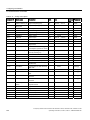
9.4
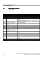
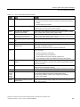
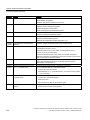
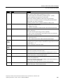
List of alarms and faults .............................................................................................................296
Technical data ....................................................................................................................................... 303
10.1
Technical data for CU230P-2.....................................................................................................303
10.2
10.2.1
10.2.2
10.2.3
10.2.4
Technical data, Power Modules.................................................................................................305
Technical data, PM230 ..............................................................................................................307
Technical data, PM240 ..............................................................................................................312
Technical data, PM250 ..............................................................................................................318
Technical data, PM260 ..............................................................................................................321
Appendix................................................................................................................................................ 323
A.1
A.1.1
A.1.1.1
A.1.1.2
A.1.1.3
A.1.1.4
A.1.1.5
A.1.2
A.1.2.1
A.1.2.2
A.1.3
Application examples .................................................................................................................323
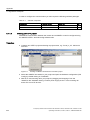
Configuring communication in STEP 7 ......................................................................................323
Task ...........................................................................................................................................323
Required components................................................................................................................323
Creating a STEP 7 project .........................................................................................................324
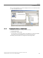
Configuring communications to a SIMATIC control ...................................................................325
Inserting the inverter into the STEP 7 project ............................................................................326
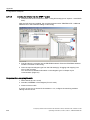
STEP 7 program examples........................................................................................................328
STEP 7 program example for cyclic communication .................................................................328
STEP 7 program example for acyclic communication ...............................................................330
Configuring slave-to-slave communication in STEP 7...............................................................334
A.2
A.2.1
Additional information on the inverter ........................................................................................336
Manuals for your inverter ...........................................................................................................336
A.3
Mistakes and improvements ......................................................................................................338
Index...................................................................................................................................................... 339
Frequency inverters with Control Units CU230P-2 HVAC, CU230P-2 DP, CU230P-2 CAN
Operating Instructions, 01/2011, FW 4.4, A5E02430659B AD
9
Table of contents
Frequency inverters with Control Units CU230P-2 HVAC, CU230P-2 DP, CU230P-2 CAN
10
Operating Instructions, 01/2011, FW 4.4, A5E02430659B AD
Introduction
1.1
1
About this manual
Who requires the operating instructions and what for?
These operating instructions primarily address fitters, commissioning engineers and machine
operators. The operating instructions describe the devices and device components and
enable the target groups being addressed to install, connect-up, parameterize, and
commission the inverters safely and in the correct manner.
What is described in the operating instructions?
These operating instructions provide a summary of all of the information required to operate
the inverter under normal, safe conditions.
The information provided in the operating instructions has been compiled in such a way that
it is sufficient for all standard applications and enables drives to be commissioned as
efficiently as possible. Where it appears useful, additional information for entry level
personnel has been added.
The operating instructions also contain information about special applications. Since it is
assumed that readers already have a sound technical knowledge of how to configure and
parameterize these applications, the relevant information is summarized accordingly. This
relates, e.g. to operation with fieldbus systems and safety-related applications.
Frequency inverters with Control Units CU230P-2 HVAC, CU230P-2 DP, CU230P-2 CAN
Operating Instructions, 01/2011, FW 4.4, A5E02430659B AD
11
Introduction
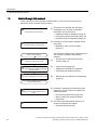
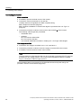
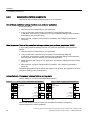
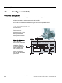
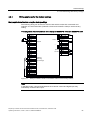
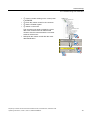
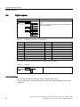
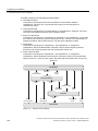
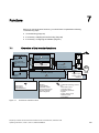
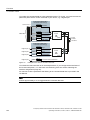
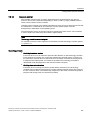
1.2 Guide through this manual
1.2
Guide through this manual
In this manual, you will find background information on your inverter, as well as a full
description of the commissioning procedure:
① Should you be unfamiliar with assigning
%DVLFV
7KHSDUDPHWHUVIRUWKHLQYHUWHU
parameters to the inverter, background
information can be found here:
• Adapting inverter to application (Page 13)
• Frequently required parameters (Page 14)
• Extended scope for adaptation (Page 16)
&RPSRQHQWVRIWKHLQYHUWHU
HJUHDFWRUVILOWHUVRSHUDWRUSDQHO
6WDUWRIFRPPLVVLRQLQJ
,QVWDOODWLRQ
found here:
• Modularity of the converter system
(Page 21)
All information relating to the commissioning of
your inverter is located in the following
chapters:
③ • Procedure for installing the frequency
,QVWDOOLQJDQGZLULQJWKHLQYHUWHU
inverter (Page 27)
$GDSWDWLRQWRWKHDSSOLFDWLRQ
④ • Commissioning (Page 53)
%DVLFFRPPLVVLRQLQJFRQILJXULQJLQWHUIDFHV
VHWWLQJIXQFWLRQV
② Information on the inverter hardware can be
• Adapting the terminal strip (Page 85)
• Configuring the fieldbus (Page 97)
'DWDEDFNXS
2Q3&3*RSHUDWRUSDQHORUPHPRU\FDUG
⑤ • Data backup and standard commissioning
(Page 78)
(QGRIFRPPLVVLRQLQJ
0DLQWHQDQFHDQGGLDJQRVWLFV
5HSODFLQJFRPSRQHQWVGLVSOD\VDODUPV
IDXOWV
7HFKQLFDOGDWD
⑥ Information regarding the maintenance and
diagnostics of your inverter is located in the
following chapters:
• Service and maintenance (Page 281)
• Alarms, faults and system messages
(Page 285)
⑦ The most important technical data for your
inverter is located in this chapter:
• Technical data (Page 303)
Frequency inverters with Control Units CU230P-2 HVAC, CU230P-2 DP, CU230P-2 CAN
12
Operating Instructions, 01/2011, FW 4.4, A5E02430659B AD
Introduction
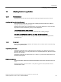
1.3 Adapting inverter to application
1.3
Adapting inverter to application
1.3.1
General basics
Inverters are used to improve and extend the starting and speed response of motors.
Adapting the inverter to the drive task
The inverter must match the motor that it is controlling and the drive task to be able to
optimally operate and protect the motor.
Although the inverter can be parameterized for very specific applications, many standard
applications function satisfactorily with just a few adaptations.
Use the factory settings (where possible)
In simple applications, the inverter already functions with its factory settings.
Only basic commissioning is required ... for simple, standard applications
Most standard applications function after just a few adaptations made during the basic
commissioning.
1.3.2
Parameter
Parameters are the interface between the firmware of the inverter and the commissioning
tool, e.g. an operator panel.
Adjustable parameters
Adjustable parameters are the "adjusting screws" with which you adapt the inverter to its
particular application. If you change the value of an adjustable parameter, then the inverter
behavior also changes.
Adjustable parameters are shown with a "p" as prefix, e.g. p1082 is the parameter for the
maximum motor speed.
Display parameters
Display parameters allow internal measured quantities of the inverter and the motor to be
read.
Display parameters are shown with a "r" as prefix, e.g. p0027 is the parameter for the
inverter output current.
Frequency inverters with Control Units CU230P-2 HVAC, CU230P-2 DP, CU230P-2 CAN
Operating Instructions, 01/2011, FW 4.4, A5E02430659B AD
13
Introduction
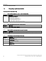
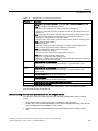
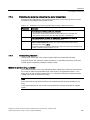
1.4 Frequently required parameters
1.4
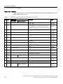
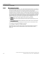
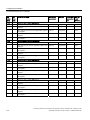
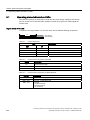
Frequently required parameters
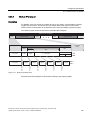
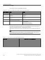
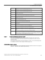
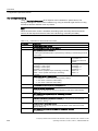
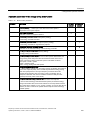
Parameters that in many cases help
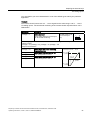
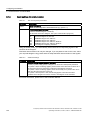
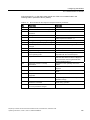
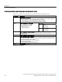
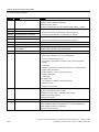
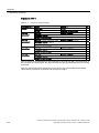
Table 1- 1
How to switch to commissioning mode or restore the factory setting
Parameter
Description
p0010
Commissioning parameters
0: Ready (factory setting)
1: Carry out basic commissioning
3: Perform motor commissioning
5: Technological applications and units
15: Define number of data records
30: Factory setting - initiate restore factory settings
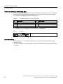
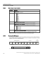
Table 1- 2
How to determine the firmware version of the Control Unit
Parameter
Description
r0018
The firmware version is displayed:
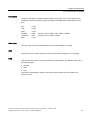
Table 1- 3
How to select the command and setpoint sources for the inverter
Parameter
Description
p0015
Additional information is available in the section Selecting the interface assignments (Page 48).
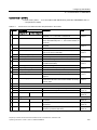
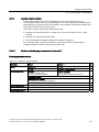
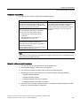
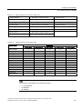
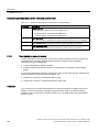
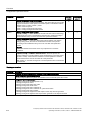
Table 1- 4
This is how you parameterize the up and down ramps
Parameter
Description
p1080
Minimum speed
0.00 [rpm] factory setting
p1082
Maximum speed
1500.000 [rpm] factory setting
p1120
Rampup time
10.00 [s]
p1121
Rampdown time
10.00 [s]
Frequency inverters with Control Units CU230P-2 HVAC, CU230P-2 DP, CU230P-2 CAN
14
Operating Instructions, 01/2011, FW 4.4, A5E02430659B AD
Introduction
1.4 Frequently required parameters
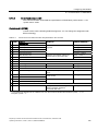
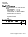
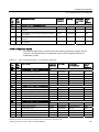
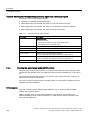
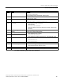
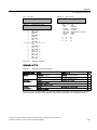
Table 1- 5
This is how you set the closed-loop type
Parameter
Description
p1300
0: V/f control with linear characteristic
1: V/f control with linear characteristic and FCC
2: V/f control with parabolic characteristic
3: V/f control with parameterizable characteristic
4: V/f control with linear characteristic and ECO
5: V/f control for drives requiring a precise frequency (textile area)
6: V/f control for drive requiring a precise frequency and FCC
7: V/f control with parabolic characteristic and ECO
19: V/f control with independent voltage setpoint
20: Speed control (without encoder)
22: Torque control (without encoder)
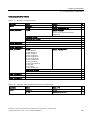
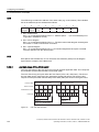
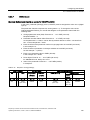
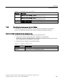
Table 1- 6
This is how you optimize the starting behavior of the V/f control for a high break loose torque and overload
Parameter
Description
p1310
Voltage boost to compensate ohmic losses
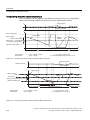
The voltage boost is active from standstill up to the rated speed.
It is at its highest at speed 0 and continually decreases as the speed increases.
Value of the voltage boost at zero speed 0 in V:
1.732 × rated motor current (p0305) × stator resistance (r0395) × p1310 / 100%
p1311
Voltage boost when accelerating
The voltage boost is effective from standstill up to the rated speed.
It is independent of the speed and has a value in V of:
1.732 × rated motor current (p0305) × stator resistance (p0350) × p1311 / 100%
p1312
Voltage boost when starting
Setting to additionally boost the voltage when starting, however only when accelerating for the first time.
Frequency inverters with Control Units CU230P-2 HVAC, CU230P-2 DP, CU230P-2 CAN
Operating Instructions, 01/2011, FW 4.4, A5E02430659B AD
15
Introduction
1.5 Extended scope for adaptation
1.5
Extended scope for adaptation
1.5.1
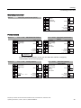
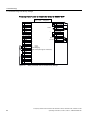
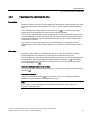
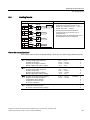
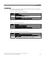
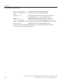
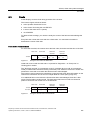
BICO technology: basic principles
Principle of operation of BICO technology
Open/closed-loop control functions, communication functions as well as diagnostic and
operator functions are implemented in the inverter. Every function comprises one or several
BICO blocks that are interconnected with one another.
Inputs
Parameter
Output
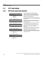
MOP
MOP output
speed
[rpm]
r1050
MOP enable (higher)
p1035
MOP enable (lower)
p1036
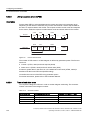
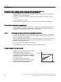
Figure 1-1
Example of a BICO block: Motorized potentiometer (MOP)
Most of the BICO blocks can be parameterized. You can adapt the blocks to your application
using parameters.
You cannot change the signal interconnection within the block. However, the interconnection
between blocks can be changed by interconnecting the inputs of a block with the appropriate
outputs of another block.
The signal interconnection of the blocks is realized, contrary to electric circuitry, not using
cables, but in the software.
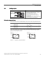
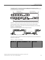
Figure 1-2
DI 0
r0722.0
p0840
Index [0]
ON/
OFF1
Example: Signal interconnection of two BICO blocks for digital input 0
Binectors and connectors
Connectors and binectors are used to exchange signals between the individual BICO blocks:
● Connectors are used to interconnect "analog" signals. (e.g. MOP output speed)
● Binectors are used to interconnect "digital" signals. (e.g. 'Enable MOP up' command)
Frequency inverters with Control Units CU230P-2 HVAC, CU230P-2 DP, CU230P-2 CAN
16
Operating Instructions, 01/2011, FW 4.4, A5E02430659B AD
Introduction
1.5 Extended scope for adaptation
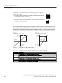
Definition of BICO technology
BICO technology represents a type of parameterization that can be used to disconnect all
internal signal interconnections between BICO blocks or establish new connections. This is
realized using Binectors and Connectors. Hence the name BICO technology. ( Binector
Connector Technology)
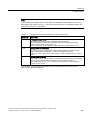
BICO parameters
You can use the BICO parameters to define the sources of the input signals of a block.
Using BICO parameters you define from which connectors and binectors a block reads-in its
input signals. This is how you "interconnect" the blocks stored in the devices according to
your particular application requirements. The five different BICO parameter types are shown
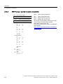
in the following diagram:
%LQHFWRULQSXW
%,
pxxxx
BICO block
&RQQHFWRULQSXW
&,
Figure 1-3
rxxxx
%LQHFWRURXWSXW
%2
rxxxx
rxxxx
%LQHFWRUFRQQHFWRU
RXWSXW
&2%2
rxxxx
&RQQHFWRURXWSXW
&2
pxxxx
BICO symbols
Binector/connector outputs (CO/BO) are parameters that combine more than one binector
output in a single word (e.g. r0052 CO/BO: status word 1). Each bit in the word represents a
digital (binary) signal. This summary reduces the number of parameters and simplifies
parameter assignment.
BICO outputs (CO, BO, or CO/BO) can be used more than once.
When do you need to use BICO technology?
BICO technology allows you to adapt the inverter to a wide range of different requirements.
This does not necessarily have to involve highly complex functions.
Example 1: Assign a different function to a digital input.
Example 2: Switch the speed setpoint from the fixed speed to the analog input.
What precautions should you take when using BICO technology?
Always apply caution when handling internal interconnections. Note which changes you
make as you go along since the process of analyzing them later can be quite difficult.
The STARTER commissioning tool offers various screens that make it much easier for you
to use BICO technology. The signals that you can interconnect are displayed in plain text,
which means that you do not need any prior knowledge of BICO technology.
Frequency inverters with Control Units CU230P-2 HVAC, CU230P-2 DP, CU230P-2 CAN
Operating Instructions, 01/2011, FW 4.4, A5E02430659B AD
17
Introduction
1.5 Extended scope for adaptation
What sources of information do you need to help you set parameters using BICO
technology?
● This manual is sufficient for simple signal interconnections, e.g. assigning a different
significance to the to digital inputs.
● The parameter list in the List Manual is sufficient for signal interconnections that go
beyond just simple ones.
● You can also refer to the function diagrams in the List Manual for complex signal
interconnections.
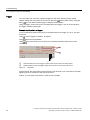
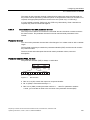
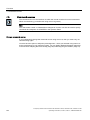
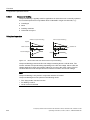
1.5.2
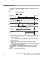
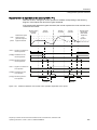
BICO technology: example
Example: Shifting a basic PLC functionality into the converter
A conveyor system is to be configured in such a way that it can only start when two signals
are present simultaneously. These could be the following signals, for example:
● The oil pump is running (the required pressure level is not reached, however, until after
five seconds)
● The protective door is closed
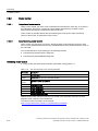
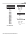
The task is realized by inserting free blocks between the digital input 0 and the internal
ON/OFF1 command and interconnecting them.
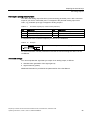
p20161 = 5 p20159 = 5000 [ms]
DI 0
DI 1
r0722.0
r0722.1
p20158
Index [0]
T
0
PDE 0
r20160
p20162 = 430
1
1
Figure 1-4
p20032 = 5 p20033 = 440
p20030
Index [0]
&
Index [1]
r20031
Index [2] AND 0
Index [3]
p0840
ON/
Index [0]
OFF1
Example: Signal interconnection for interlock
The signal of digital input 0 (DI 0) is fed through a time block (PDE 0) and is interconnected
with the input of a logic block (AND 0). The signal of digital input 1 (DI 1) is interconnected to
the second input of the logic block. The logic block output issues the ON/OFF1 command to
switch-on the motor.
Frequency inverters with Control Units CU230P-2 HVAC, CU230P-2 DP, CU230P-2 CAN
18
Operating Instructions, 01/2011, FW 4.4, A5E02430659B AD
Introduction
1.5 Extended scope for adaptation
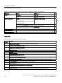
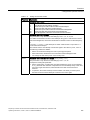
Table 1- 7
Parameterizing an interlock
Parameter
Description
P20161 = 5
The time block is enabled by assigning to runtime group 5 (time slice of
128 ms)
P20162 = 430
Run sequence of the time block within runtime group 5 (processing before
the AND logic block)
P20032 = 5
The AND logic block is enabled by assigning to runtime group 5 (time
slice of 128 ms)
P20033 = 440
Run sequence of the AND logic block within runtime group 5 (processing
after the time block)
P20159 = 5000.00
Setting the delay time [ms] of the time module: 5 seconds
P20158 = 722.0
Connect the status of DI 0 to the input of the time block
r0722.0 = Parameter that displays the status of digital input 0.
P20030 [0] = 20160
P20030 [1] = 722.1
Interconnecting the time block to the 1st input of the AND
Interconnecting the status of DI 1 to the 2nd AND input
r0722.1 = Parameter that displays the status of digital input 1.
P0840 = 20031
Interconnecting the AND output to the control command ON/OFF1
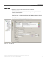
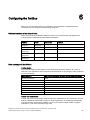
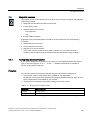
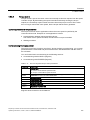
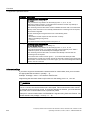
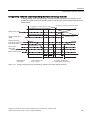
Explanation of the example using the ON/OFF1 command
Parameter P0840[0] is the input of the "ON/OFF1 command" block of the converter.
Parameter r20031 is the output of the AND block. To interconnect the ON/OFF1 command
with the output of the AND block, set P0840 to 20031.
p0840[0] = 20031
p20030
Index [0]
&
r20031
Index [1]
AND 0
Index [2]
Index [3]
Figure 1-5
p0840
ON/
Index [0] OFF1
Interconnecting two BICO blocks by setting p0840[0] = 20031
Principle when connecting BICO blocks using BICO technology
An interconnection between two BICO blocks comprises a connector or binector and a BICO
parameter. The interconnection is always established from the perspective of the input of a
particular BICO block. This means that the output of an upstream block must always be
assigned to the input of a downstream block. The assignment is always made by entering
the number of the connector/binector from which the required input signals are read in a
BICO parameter.
This interconnection logic involves the question: where does the signal come from?
Frequency inverters with Control Units CU230P-2 HVAC, CU230P-2 DP, CU230P-2 CAN
Operating Instructions, 01/2011, FW 4.4, A5E02430659B AD
19
Introduction
1.5 Extended scope for adaptation
Frequency inverters with Control Units CU230P-2 HVAC, CU230P-2 DP, CU230P-2 CAN
20
Operating Instructions, 01/2011, FW 4.4, A5E02430659B AD
2
Description
2.1
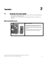
Modularity of the converter system
Thanks to their modular design, the converters can be used in a wide range of applications
with respect to functionality and power.
The following overview describes the converter components, which you require for your
application.
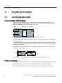
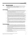
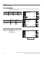
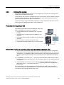
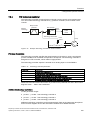
Main components of the converter
Each SINAMICS G120 converter comprises a Control
Unit and Power Module.
3RZHU0RGXOH
•
The Control Unit controls and monitors the Power
Module and the connected motor in various control
modes (which can be selected as required). The
Control Unit is used to control the converter locally or
centrally.
•
The Power Modules are available for motors with a
power range of between 0.37 kW and 250 kW.
&RQWURO8QLW
Frequency inverters with Control Units CU230P-2 HVAC, CU230P-2 DP, CU230P-2 CAN
Operating Instructions, 01/2011, FW 4.4, A5E02430659B AD
21
Description
2.1 Modularity of the converter system
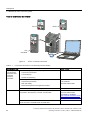
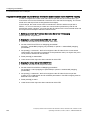
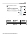
Tools to commission the inverter
,23
%23
,23
+DQGKHOG
Figure 2-1
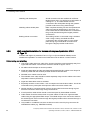
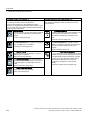
Table 2- 1
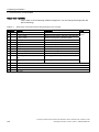
Tools to commission the inverter
Components and tools for commissioning and data backup
Component or tool
Operator panel for
commissioning,
diagnostics and
controlling
frequency
converters
Tools for the PC
Order number
BOP-2 - for snapping onto the frequency converter
•
Copies drive parameters
•
Two-line display
•
Guided commissioning
IOP - to snap onto the frequency converter or with the handheld
6SL3255-0AA00-4CA1
6SL3255-0AA00-4JA0
IOP Handheld:
6SL3255-0AA00-4HA0
•
Copies drive parameters
•
Plain text display
•
Menu-based operation and application wizards
IOP/BOP-2 Mounting Kit IP54/UL Type 12
6SL3256-0AP00-0JA0
STARTER commissioning tool (PC software)
connected to the frequency converter via USB cable
STARTER on DVD:
6SL3072-0AA00-0AG0
Downloading: STARTER
(http://support.automation.sieme
ns.com/WW/view/en/10804985/1
30000)
PC Connection Kit
The kit contains a STARTER DVD and USB cable
6SL3255-0AA00-2CA0
Frequency inverters with Control Units CU230P-2 HVAC, CU230P-2 DP, CU230P-2 CAN
22
Operating Instructions, 01/2011, FW 4.4, A5E02430659B AD
Description
2.1 Modularity of the converter system
Component or tool
Order number
Drive ES Basic
To commission the frequency converter via the PROFIBUS
interface. Includes STARTER
6SW1700-5JA00-4AA0
Memory card to save and transfer the
frequency converter settings
MMC card
6SL3254-0AM00-0AA0
SD card
6ES7954-8LB00-0AA0
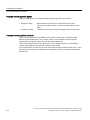
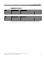
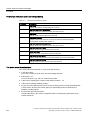
Components which you require depending on your particular application
Filters and reactors
● Line filters, Classes A and B
● Line reactors
● Braking resistors
● Output reactors
● Sine-wave filter
Further options
● Adapter for DIN rail mounting (only PM240, FSA)
● Shield plate (for Control Units and Power Module)
Frequency inverters with Control Units CU230P-2 HVAC, CU230P-2 DP, CU230P-2 CAN
Operating Instructions, 01/2011, FW 4.4, A5E02430659B AD
23
Description
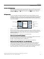
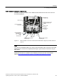
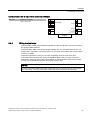
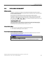
2.2 Control Units
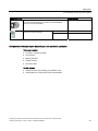
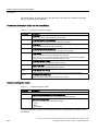
2.2
Control Units
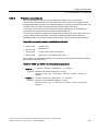
The CU230P 2 Control Units have integrated technology functions for pumps, fans and
compressor applications. The I/O interfaces, the fieldbus interface and the specific software
functions optimally support these applications. The integration of technological functions is a
significant differentiating feature to the other Control Units of the SINAMICS G120 drive
family.
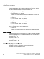
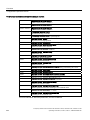
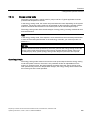
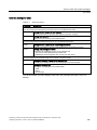
CU230P-2-specific functions
● Essential service mode
● Multi-zone controller
● Cascade control
● Energy-saving mode
● Bypass
The CU230P-2 is available with the following communications
interfaces:
• As CU230P-2 HVAC with RS485 interface for:
– USS
– Modbus RTU
– BACnet MS/TP
• As CU230P-2 DP for PROFIBUS DP
• As CU230P-2 CAN for CANopen
Frequency inverters with Control Units CU230P-2 HVAC, CU230P-2 DP, CU230P-2 CAN
24
Operating Instructions, 01/2011, FW 4.4, A5E02430659B AD
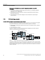
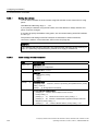
Description
2.3 Power Module
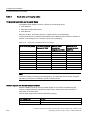
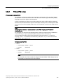
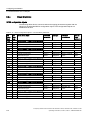
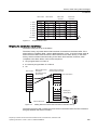
2.3
Power Module
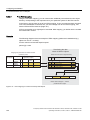
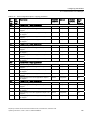
Power Modules are available in various degrees of protection with a different topology in the
power range from between 0.37 kW up to 250 kW. The Power Modules are sub-divided into
various frame sizes (FS).
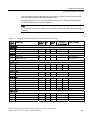
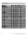
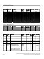
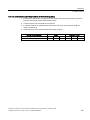
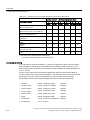
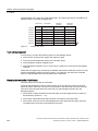
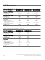
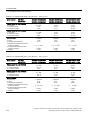
Power Modules with degree of protection IP20: PM240, PM250, PM260
Frame size
FSA
FSB
FSC
FSD
FSE
FSF
FSGX
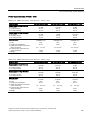
PM240, 3AC 400V - power units with integrated braking chopper1)
Power range (LO) in kW
line filter, Class A
0.37 … 1.5
2.2 … 4
7.5 … 15
18.5 … 30
37 … 45
55 … 132
160 … 250
○
●
●
●
●
◑
◑
PM250, 3AC 400V - power units capable of energy recovery
Power range (LO) in kW
---
---
line filter, Class A
---
---
7.5 … 15
18.5 … 30
37 … 45
●
●
●
55 … 90
●
-----
PM260, 3AC 690V - power units capable of energy recovery
Power range (LO) in kW
---
---
---
11 … 18.5
---
line filter, Class A
---
---
---
○/●
---
30 … 55
○/●
-----
Sine-wave filter
---
---
---
●
---
●
---
○ = without; ● = integrated; ◑ = from 110 kW for external mounting
1) The Power Module PM240 FSGX is supplied without braking chopper, but is prepared for installation of an optional
braking chopper
Frequency inverters with Control Units CU230P-2 HVAC, CU230P-2 DP, CU230P-2 CAN
Operating Instructions, 01/2011, FW 4.4, A5E02430659B AD
25
Description
2.4 Reactors and filters
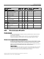
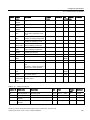
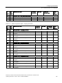
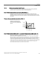
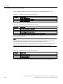
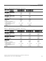
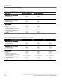
PM230 Power Module, IP55 degree of protection / UL Type 12
Frame size
FSA
FSB
FSC
FSD
FSE
FSF
PM230, 3AC 400V - power units with low line reactions
Power range (LO) in kW
0,37 … 3
4 … 7,5
11 … 18.5
22 … 30
37 … 45
55 … 90
line filter, Class A
●
●
●
●
●
●
line filter, class B
●
●
●
●
●
●
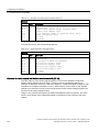
2.4
Reactors and filters
Depending on the Power Module, the following combinations with filters and reactors are
permitted:
Line-side components
Power Module
Line reactor
Line filters
class B
Load-side components
Braking
Sine-wave filter
Output reactor
resistor
PM230
-
-
-
-
-
PM240
●
●
●
●
●
PM250
-
●
-
●
●
For further details, refer to the connection example in section Procedure for installing the
frequency inverter (Page 27).
Frequency inverters with Control Units CU230P-2 HVAC, CU230P-2 DP, CU230P-2 CAN
26
Operating Instructions, 01/2011, FW 4.4, A5E02430659B AD
3
Installing
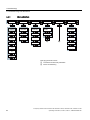
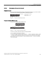
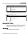
3.1
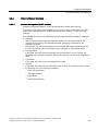
Procedure for installing the frequency inverter
Preconditions for installation
Check that the following preconditions are fulfilled before installing:
● Are the required components, tools and small parts available?
● Are the ambient conditions permissible? See Technical data (Page 303).
Installation sequence
3UHUHTXLVLWHVIRULQVWDOODWL
RQKDYHEHHQIXOILOOHG
,QVWDOOLQJUHDFWRUV
DQGILOWHUV
,QVWDOOLQJWKH3RZHU
0RGXOH
① Installing reactors and filters (Page 28)
② Installing Power Module (Page 30)
,QVWDOOLQJ&RQWURO8QLW
③ Installing Control Unit (Page 44)
,QVWDOODWLRQFRPSOHWHG
You will find details on the installation in the Internet: Hardware Installation Manual
(http://support.automation.siemens.com/WW/view/en/30563173/133300).
You can start to commission the converter once installation has been completed.
Frequency inverters with Control Units CU230P-2 HVAC, CU230P-2 DP, CU230P-2 CAN
Operating Instructions, 01/2011, FW 4.4, A5E02430659B AD
27
Installing
3.2 Installing reactors and filters
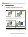
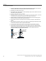
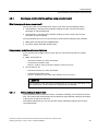
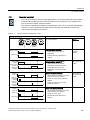
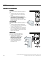
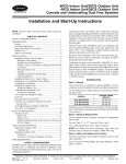
3.2
Installing reactors and filters
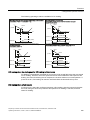
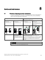
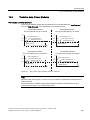
Fitting inverter system components in space-saving manner
Many inverter system components are designed as base components, that is, the
component is mounted on the baseplate and the inverter mounted above it to save space.
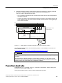
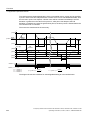
Up to two base components can be mounted above one another.
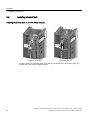
PM240
Line supply
Power
Modules
Line
filter
Power
Modules
Line
reactor
Line
reactor
Line supply
Basic layout of a PM240 Power Module with line
reactor as base component
PM240 Power Module frame size FSA with line
reactor and class A line filter
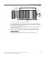
The line-side reactors are equipped with terminals while the reactors on the Power Module side are
equipped with a prefabricated cable. In the final installation position, the mains terminals are at the
top on frame sizes FSA to FSC, and at the bottom on frame sizes FSD to FSE.
For frame size FSA, in addition to the line reactor, a class A line filter can be used. In this case, the
mains connection is at the bottom.
Power Modules of frame size FSB and higher are available with integrated class A line filters (an
external class A line filter is not required in this case).
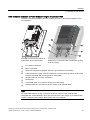
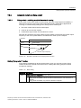
Line
Line
supply
reactor
Power
Module
Output reactor
or sine-wave
filter
Line reactor
Line filter
Power
Module
Output reactor
or sine-wave
filter
Line
supply
to the motor
to the motor
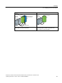
PM240: frame size FSA with line reactor and
output reactor or sine-wave filter
PM240 Power Module frame size FSA with line
reactor, line filter and output reactor or sine-wave
filter
In installations containing more than two base-type system components (e.g. line filter + line reactor +
output reactor), the components must be installed to the side of the Power Module whereby the line
reactor and line filter are installed under the Power Module and the output reactor to the side.
Frequency inverters with Control Units CU230P-2 HVAC, CU230P-2 DP, CU230P-2 CAN
28
Operating Instructions, 01/2011, FW 4.4, A5E02430659B AD
Installing
3.2 Installing reactors and filters
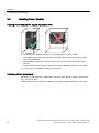
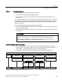
PM250
Line
Line filter supply
Power
Module
Line supply
Output reactor or
sine-wave filter
Power
Modules
Line filter
to the motor
Basic layout of a PM250 Power Module with class Basic layout of a PM250 Power Module with a
B line filter as a base component
class B line filter as a base component and
output reactor or sine-wave filter
Frequency inverters with Control Units CU230P-2 HVAC, CU230P-2 DP, CU230P-2 CAN
Operating Instructions, 01/2011, FW 4.4, A5E02430659B AD
29
Installing
3.3 Installing Power Module
3.3
Installing Power Module
Installing Power Modules with degree of protection IP20
● Install the Power Module vertically on a mounting plate in a control cabinet.
The smaller frame sizes of the converter (FSA and FSB) can also be mounted on DIN
rails using an adapter.
● When installing, observe the minimum clearances to other components in the control
cabinet.
These minimum clearances are necessary to ensure adequate cooling of the converter.
● Do not cover the ventilation openings the converter.
Installing additional components
Depending on the application, additional line reactors, filters, braking resistors, brake relays
etc., may also be used.
Please observe the mounting and installation instructions supplied with these components.
Frequency inverters with Control Units CU230P-2 HVAC, CU230P-2 DP, CU230P-2 CAN
30
Operating Instructions, 01/2011, FW 4.4, A5E02430659B AD
Installing
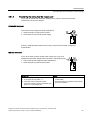
3.3 Installing Power Module
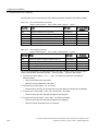
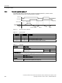
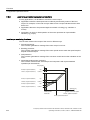
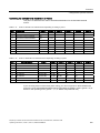
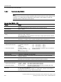
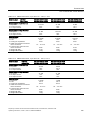
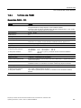
3.3.1
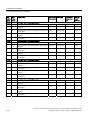
Dimensions, hole drilling templates, minimum clearances, tightening torques
Note
For Power Modules up to 132 kW, degree of protection IP20, the CU230P-2 increases the
total inverter depth by 50 mm - and an additional 30 mm if you use an IOP.
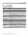
Dimensions and drilling patterns for the PM230 Power Modules
G
&RROLQJ
DLU
F
Figure 3-1
Table 3- 1
Frame size
E
:LGWK
D
G
'HSWK
+HLJKW
F
'LVVLSDWHG
KHDW
'HSWK
Drilling pattern for PM230
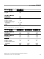
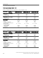
Dimensions for PM230, IP55
Dimensions (mm)
Clearances (mm)
Height
Width
Depth
a
b
c
d
FSA
460
154
238
445
132
100
0
FSB
540
180
238
524
158
100
0
FSC
620
230
238
604
208
125
0
FSD
640
320
238
600
285
300
0
FSE
751
320
238
710
285
300
0
915
410
238
870
370
300
0
FSF
Fixing:
FSA/FSB: screws M4, 2.5 Nm,
FSC: screws M5, 2.5 Nm,
FSD/FSE/FSF: screws M8, 13 Nm
Frequency inverters with Control Units CU230P-2 HVAC, CU230P-2 DP, CU230P-2 CAN
Operating Instructions, 01/2011, FW 4.4, A5E02430659B AD
31
Installing
3.3 Installing Power Module
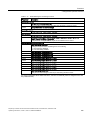
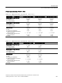
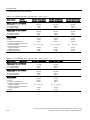
Dimensions and drilling patterns for the PM240 Power Modules
:LGWK
'HSWK &RQWURO8QLW
)6$)6)
ODWHUDO
)6$)6*;
ODWHUDO
)6$)6*;
ERWWRP
'HSWK
E
E
F
&RROLQJDLU
+HLJKW
WRS
7KHUPDO
GLVVLSDWLRQ
F
E
E
D
D
D
F
)6*;
Figure 3-2
Table 3- 2
Frame size
)6%)6)
)6$
PM240 drilling pattern
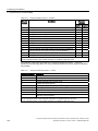
PM240, IP20 dimensions
Dimensions (mm)
Height
Width
Clearances (mm)
Depth
FSA
173
73
145
FSB
270
153
165
FSC
334
189
185
FSD without filter
419
275
204
FSD with filter, Class A
512
275
204
FSE without filter
499
275
204
FSE with filter, Class A
635
275
204
FSF without filter
634
350
316
FSF with filter, Class A
934
350
316
FSGX
1533
326
547
Fixing:
FSA/FSB: M4 screws, 2.5 Nm / 22 lbf .in
FSD/FSE: M6 screws, 6 Nm/53 lbf .in
a
160
258
323
325
419
405
541
598
899
1506
b
c
top
bottom
lateral
36.5
-100
100
30*
133
-100
100
40*
167
-125
125
50*
235
11
300
300
0
235
11
300
300
0
235
11
300
300
0
235
11
300
300
0
300
11
350
350
0
300
11
350
350
0
125
14.5
250
150
50
FSC: M5 screws, 2.5 Nm / 22 lbf .in FSF/FSGX: M8
screws, 13 Nm / 115 lbf .in
*) up to 40 °C without any lateral clearance
Frequency inverters with Control Units CU230P-2 HVAC, CU230P-2 DP, CU230P-2 CAN
32
Operating Instructions, 01/2011, FW 4.4, A5E02430659B AD
Installing
3.3 Installing Power Module
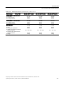
Dimensions and drilling patterns for the PM250 Power Modules
:LGWK
'HSWK &RQWURO8QLW
E
ODWHUDO
)6&)6)
&RROLQJ
DLU
)6&)6)
'HSWK
Figure 3-3
PM250 drilling pattern
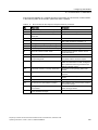
Table 3- 3
PM250, IP20 dimensions
Frame size
)6&)6)
+HLJKW
)6&)6)
ERWWRP
ODWHUDO
D
F
WRS
7KHUPDO
GLVVLSDWLRQ
Dimensions (mm)
Height
Width
Clearances (mm)
Depth
a
b
c
top
bottom
lateral
FSC
334
189
185
323
167
--
125
125
50*
FSD without filter
419
275
204
325
235
11
300
300
0
FSD with filter, Class A
512
275
204
419
235
11
300
300
0
FSE without filter
499
275
204
405
235
11
300
300
0
FSE with filter, Class A
635
275
204
541
235
11
300
300
0
FSF without filter
634
350
316
598
300
11
350
350
0
FSF with filter, Class A
934
350
316
899
300
11
350
350
0
Fixing:
FSB: M4 screws, 2.5 Nm / 22 lbf .in FSD/FSE:
M6 screws, 6 Nm/53 lbf .in
FSC: M5 screws, 2.5 Nm / 22 lbf .in FSF/: M8
screws, 13 Nm / 115 lbf .in
*) up to 40 °C without any lateral clearance
Frequency inverters with Control Units CU230P-2 HVAC, CU230P-2 DP, CU230P-2 CAN
Operating Instructions, 01/2011, FW 4.4, A5E02430659B AD
33
Installing
3.3 Installing Power Module
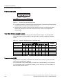
Dimensions and drilling patterns for the PM260 Power Modules
:LGWK
E
F
WRS
'HSWK &RQWURO8QLW
)6')6)
)6')6)
)6')6)
D
ODWHUDO
+HLJKW
)6')6)
ERWWRP
ODWHUDO
'HSWK
Figure 3-4
PM260 drilling pattern
Table 3- 4
PM260, IP20 dimensions
Frame size
Dimensions (mm)
Clearances (mm)
Height
Width
Depth
a
b
c
top
bottom
lateral
FSD without / with filter
419
275
204
419
235
11
300
300
30*
FSF without / with filter
634
350
316
598
300
11
350
350
0
Fixing:
FSD: M6 screws, 6 Nm/53 lbf.in
FSF: M8 screws, 13 Nm / 115 lbf.in
*) up to 40 °C without any lateral clearance
Frequency inverters with Control Units CU230P-2 HVAC, CU230P-2 DP, CU230P-2 CAN
34
Operating Instructions, 01/2011, FW 4.4, A5E02430659B AD
Installing
3.3 Installing Power Module
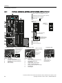
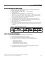
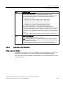
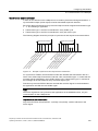
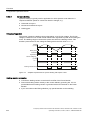
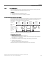
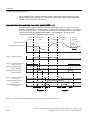
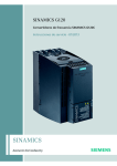
3.3.2
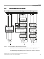
Connection overview for Power Modules
/
/
/
3(
8 9 : 3(
/LQHUHDFWRU 8 9 : 3(
%UDNLQJ
UHVLVWRU
/ / / 3(
/ / / 3(
/LQHILOWHUH[WHUQDO /LQHILOWHUH[WHUQDO
/ಬ /ಬ /ಬ 3(ಬ
/ಬ /ಬ /ಬ 3(ಬ
8 9 : 3(
8 9 : 3(
3RZHU0RGXOH
30
3(
8 9 : 3(
3RZHU0RGXOH
30
8 9 : 3(
8 9
5
5
3RZHU0RGXOH30
8 9 : 3(
8 9 : 3(
8 9 : 3(
6LQHZDYHILOWHURU
2XWSXWUHDFWRU 8 9 : 3(
8 9 : 3(
6LQHZDYHILOWHURU
2XWSXWUHDFWRU 8 9 : 3(
:
3(
0
8 9
:
3(
0
8 9
:
3(
0
$FFHVVRULHV
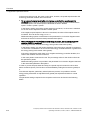
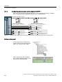
Figure 3-5
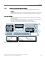
Connections for PM230, PM240 and PM250 Power Modules
PM240 and PM250 Power Modules are available with and without integrated class A line
filters. Either a Class A or a Class B filter is integrated in the PM230 Power Module.
An external filter has to be installed in PM240 and PM250 Power Modules to satisfy more
stringent EMC requirements (Class B).
Frequency inverters with Control Units CU230P-2 HVAC, CU230P-2 DP, CU230P-2 CAN
Operating Instructions, 01/2011, FW 4.4, A5E02430659B AD
35
Installing
3.3 Installing Power Module
3.3.3
Connecting the line supply and motor
Preconditions
Once the inverter has been properly installed, the line and motor connections can now be
established. The following warning information must be observed here.
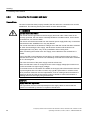
WARNING
Line and motor connections
The inverter must be grounded on the line supply and motor side. If the inverter is not
correctly grounded, this can lead to extremely hazardous conditions which, under certain
circumstances, can result in death.
The device must be disconnected from the electrical power supply before any connections
with the device are established or in any way altered.
The inverter terminals be at hazardous voltages even after the inverter has been switched
off. After disconnecting the line supply, wait at least 5 minutes until the device has
discharged itself. Only then, carry out any installation and mounting work.
When connecting the inverter to the line supply, ensure that the motor terminal box is
closed.
Even if the LED or other indicators do not light up or remain inactive when a function is
switched from ON to OFF, this does not necessarily mean that the unit has been switched
off or is de-energized.
The short-circuit ratio of the power supply must be at least 100.
Make sure that the inverter is configured for the correct supply voltage (the inverter must
not be connected to a higher supply voltage).
If a residual-current circuit breaker is installed on the supply side of the electronic devices
to protect against direct or indirect contact, only type B is permissible. In all other cases,
other protective measures must be implemented, such as creating a barrier between the
electronic devices and the environment by means of double or reinforced insulation or
isolating them from the supply using a transformer.
CAUTION
Supply cable and signal lines
The signal lines must be routed separately from the supply cables to ensure that the
system is not affected by inductive or capacitive interference.
Frequency inverters with Control Units CU230P-2 HVAC, CU230P-2 DP, CU230P-2 CAN
36
Operating Instructions, 01/2011, FW 4.4, A5E02430659B AD
Installing
3.3 Installing Power Module
Note
Electrical protective equipment
Ensure that the appropriate circuit breakers / fuses for the inverter's rated current are fitted
between the line and inverter (see catalog D11.1).
Connecting the motor: Star connection and delta connection
With SIEMENS motors, you will see a
diagram of both connection methods on
the inside of the cover of the terminal
box:
:
8
9
:
8
9
• Star connection (Y)
• Delta connection (Δ)
8
9
:
8
9
:
The motor rating plate provides
information about the correct connection
data.
'HOWDFRQQHFWLRQ
6WDUFRQQHFWLRQ
8
8
9
:
9
:
Examples for operating the inverter and motor on a 400 V line supply
Assumption: The motor rating plate states 230/400 V Δ/Y.
Example 1: A motor is normally operated between standstill and its rated speed (i.e. a speed
corresponding to the line frequency). In this case, you need to connect the motor in Y.
Operating the motor above its rated speed is only possible in field weakening, i.e. the motor
torque available is reduced above the rated speed.
Example 2: If you want to operate the motor with the "87 Hz characteristic", you need to
connect the motor in Δ.
With the 87 Hz characteristic, the motor's power output increases. The 87 Hz characteristic
is mainly used with geared motors.
Frequency inverters with Control Units CU230P-2 HVAC, CU230P-2 DP, CU230P-2 CAN
Operating Instructions, 01/2011, FW 4.4, A5E02430659B AD
37
Installing
3.3 Installing Power Module
Connecting the inverter
Motor connection
● If available, open the terminal covers of the inverter.
● Connect the motor to terminals U2, V2 and W2.
Carefully observe the regulations for EMC-compliant wiring:
EMC-compliant connection (Page 39)
EMC-compliant installation for devices with degree of protection IP55 / UL Type 12
(Page 42)
● Connect the protective conductor of the motor to the terminal
The following cable lengths are permissible:
of the inverter.
– Unshielded 100 m
– Shielded:
50 m for inverters without filter
25 m for inverters with filter
You will wind additional information in Catalog D11.1 for longer cable lengths
Line supply connection
● Connect the line supply to terminals U1/L1, V1/L2 and W1/L3.
● Connect the protective conductor of the line supply to terminal PE of the inverter.
● If available, close the terminal covers of the inverter.
Note
Inverters without an integrated line filter can be connected to grounded (TN, TT) and nongrounded (IT) line supply systems. The inverters with integrated line filter are suitable
only for connection to TN line supply systems.
The permissible cable cross sections for the individual devices and power ratings are
provided in Section Technical data (Page 303).
Frequency inverters with Control Units CU230P-2 HVAC, CU230P-2 DP, CU230P-2 CAN
38
Operating Instructions, 01/2011, FW 4.4, A5E02430659B AD
Installing
3.3 Installing Power Module
3.3.4
EMC-compliant connection
The inverters are designed for operation in industrial environments where high values of
electromagnetic interference are expected. Safe, reliable and disturbance-free operation is
only guaranteed if the devices are professionally installed.
Inverters with degree of protection IP20 must be installed and operated in an enclosed
control cabinet.
Control cabinet design
● All metal parts and components of the control cabinet (side panels, rear panels, roof and
base plates) must be connected to the control cabinet frame through a good electrical
connection – this is best achieved using the highest possible surface area or a high
number of individual screw connections
● The PE bar and the EMC shield bar must be connected to the control cabinet frame
through a good electrical connection established through a large surface area.
● All of the metal enclosures of the devices and supplementary components installed in the
cabinet – e.g. inverter or line filter – must be connected to the control cabinet frame
through a good electrical connection through the largest possible surface area. The most
favorable design is to mount these devices and supplementary components on a bare
metal mounting plate with good conducting characteristics; this in turn is connected to the
control cabinet frame through a good electrical connection and the largest possible
surface area. It is especially important that they are connected to the PE and EMC shield
bars.
● All of the connections must be implemented so that they are durable. Screw connections
to painted or anodized metal components must either be established using special
contact (serrated) washers that cut through the insulating surface and therefore establish
a metallic conductor contact, or the insulating surface must be removed at the contact
locations.
● Coils of contactors, relays, solenoid valves and motor holding brakes must be equipped
with interference suppression elements in order to dampen high-frequency radiation
when switching-off (RC elements or varistors with AC coils and free-wheeling diodes or
varistors for DC coils). The protective circuit must be directly connected at the coil.
Cable routing and shielding
● All inverter power cables (line supply cables, connecting cables between the braking
chopper and the associated braking resistance as well as the motor cables) must be
separately routed away from signal and data cables. The minimum clearance should be
approx. 25 cm. As an alternative, the decoupling can be realized in the control cabinet
using metal partitions (separating elements) connected to the mounting plate through a
good electrical connection
● The cables from the line supply to the line filter must be routed separately away from nonfiltered power cables with a high noise level (cables between the line filter and inverter,
connecting cables between the braking chopper and the associated braking resistor as
well as motor cables)
● Signal and data cables as well as filtered line supply cables may only cross non-filtered
power cables at right angles
● All cables should be kept as short as possible
Frequency inverters with Control Units CU230P-2 HVAC, CU230P-2 DP, CU230P-2 CAN
Operating Instructions, 01/2011, FW 4.4, A5E02430659B AD
39
Installing
3.3 Installing Power Module
● Signal and data cables and the associated equipotential bonding cables must always be
routed in parallel with the smallest possible clearance between them
● Shielded motor cables must be used
● The shielded motor cable should be routed separately away from the cables to the motor
temperature sensors (PTC/KTY)
● Signal and data cables must be shielded.
● Especially sensitive control cables - such as setpoint and actual value cables - should be
routed without any interruption with optimum shield support at both ends
● Shields should be connected at both ends to the grounded enclosures through a good
electrical connection and through a large surface area
● Cable shields should be connected as close as possible to where the cable enters the
cabinet
● EMC shield bars should be used for power cables; the shield support elements provided
in the inverter should be used for signal and data cables
● If at all possible, cable shields should not be interrupted by intermediate terminals
● Cable shields should be retained both for power cables as well as for signal and data
cables using the appropriate EMC clamps. The shield clamps must connect the shield to
the EMC shield bar or the shield support element for control cables through a low
inductive connection through a large surface area.
3UHVVFDEOH
VFUHHQRQ
VKLHOGSODWH
8QFRYHU
FDEOH
VFUHHQ
$
$
Figure 3-6
Shield support
Frequency inverters with Control Units CU230P-2 HVAC, CU230P-2 DP, CU230P-2 CAN
40
Operating Instructions, 01/2011, FW 4.4, A5E02430659B AD
Installing
3.3 Installing Power Module
EMC-compliant installation of Power Modules in degree of protection IP20
The EMC-compliant installation of power modules is shown in the following diagram using
two examples.
Example for a connection without a
shield plate via an external filter
Example for a connection with a shield plate, directly
to the line supply
①
②
③
④
Line supply connection
⑤
⑥
⑦
⑧
Shielded cable for the motor connection
Motor connection
Metal mounting plate (unpainted and with a good electrical conductivity)
Cable clamps for a good conductive electrical connection through a large surface area
between the shield and mounting plate or shield plate.
Shield plate
Unshielded cable for connection directly to the line supply
Shielded cable for connection to the line supply via an external filter.
Note
An unshielded cable for the line connection should be used for Power Modules with
integrated filter. Power Modules, which are connected to the line supply via an external filter,
require a shielded cable between the line filter and Power Module.
Frequency inverters with Control Units CU230P-2 HVAC, CU230P-2 DP, CU230P-2 CAN
Operating Instructions, 01/2011, FW 4.4, A5E02430659B AD
41
Installing
3.3 Installing Power Module
3.3.5
Shielding with shield plate:
Shield connection kits are available for all Power
Module frame sizes (you will find more information in
Catalog D11.1). The cable shields must be
connected to the shield plate through the greatest
possible surface area using shield clamps.
Shielding without shield plate:
EMC-compliant shielding can also be implemented
without an optional shield plate. In this case, you
must ensure that the cable shields are connected to
the ground potential through the largest possible
surface area.
Braking resistor connection:
The braking resistor is connected using a shielded
cable. Using a clamp, the shield should be
connected to the mounting plate or to the shield
plate through a good electrical connection and
through the largest possible surface area.
EMC-compliant installation for devices with degree of protection IP55 /
UL Type 12
Inverters with degree of protection IP55 / UL Type 12 (Power Module PM230) can be
installed and operated in a closed control cabinet as well as without a control cabinet.
Cable routing and shielding
● Line supply cable and motor cable of the inverter should be routed separately away from
signal and data cables. The minimum clearance should be approx. 25 cm
● All cables should be kept as short as possible
● Signal and data cables and the associated equipotential bonding cables must always be
routed in parallel with the smallest possible clearance between them
● Shielded motor cables must be used
● The shielded motor cable should be routed separately away from the cables to the motor
temperature sensors (PTC/KTY)
● Signal and data cables must be shielded.
● Especially sensitive control cables - such as setpoint and actual value cables - should be
routed without any interruption with optimum shield connection at both ends
● Shields should be connected at both ends to the grounded enclosures through a good
electrical connection and through a large surface area
● If at all possible, cable shields should not be interrupted by intermediate terminals
● Cable shields should be retained both for power cables as well as for signal and data
cables using the appropriate EMC clamps. The shield clamps must connect the shield to
the shield support of the inverter through the largest possible surface area and through a
low inductive connection
● Only metallic or metallized connector enclosures must be used for plug connectors for
shielded data cables (e.g. PROFIBUS cables)
Frequency inverters with Control Units CU230P-2 HVAC, CU230P-2 DP, CU230P-2 CAN
42
Operating Instructions, 01/2011, FW 4.4, A5E02430659B AD
Installing
3.3 Installing Power Module
EMC-compliant installation of the inverter
The EMC-compliant installation of the PM230 Power Module and Control Unit is shown in
the following diagram.
&RQWUROOLQH
&RQWURO8QLW
6WUDLQUHOLHI
6KLHOGFRQQHFWLRQZLWK
DODUJHVXUIDFHDUHD
6KLHOG
/LQHVXSSO\FDEOH
XQVKLHOGHG
0RWRUFDEOH
VKLHOGHG
&RQWUROOLQH
VKLHOGLQJ
*RRGFRQGXFWLYH
FRQQHFWLRQIRU
KLJKIUHTXHQF\
(0&
GLVWXUEDQFHV
(0&JODQG
6WDQGDUGKHDY\JDXJH
WKUHDGHGMRLQW
Figure 3-7
6WDQGDUGKHDY\JDXJH
WKUHDGHGMRLQW
EMC-compliant connection of the Power Module PM230, degree of protection IP55 / UL
Type 12
Note
You must use a shielded cable if you use the control terminals of the Control Unit. The cable
shield must be connected to the gland plate through a good electrical connection using an
EMC gland.
Additional information is available in the installation instructions for the Power Module
PM230 (http://support.automation.siemens.com/WW/view/en/30563173/133300).
Frequency inverters with Control Units CU230P-2 HVAC, CU230P-2 DP, CU230P-2 CAN
Operating Instructions, 01/2011, FW 4.4, A5E02430659B AD
43
Installing
3.4 Installing Control Unit
3.4
Installing Control Unit
Installing the Control Unit on an IP20 Power Module
Plugging on the CU
Removing the CU
To gain access to the terminal strips, open the top and bottom front doors to the right. The
terminal strips use spring-loaded terminals.
Frequency inverters with Control Units CU230P-2 HVAC, CU230P-2 DP, CU230P-2 CAN
44
Operating Instructions, 01/2011, FW 4.4, A5E02430659B AD
Installing
3.4 Installing Control Unit
IP55 Power Modules
Figure 3-8
DQG
3OXJJLQJRQWKH&8
5HPRYH&8IRU)6$WR)6&
IRU)6'WR)6)WKHXQODWFKLQJEXWWRQLV
DFFHVVLEOHIURPWKHWRS
Locate the CU on the PM
You will find a detailed description in the associated Hardware Installation Manual.
Frequency inverters with Control Units CU230P-2 HVAC, CU230P-2 DP, CU230P-2 CAN
Operating Instructions, 01/2011, FW 4.4, A5E02430659B AD
45
Installing
3.4 Installing Control Unit
3.4.1
Interfaces, connectors, switches, control terminals, LEDs on the CU
6ORWIRUPHPRU\FDUG00&RU6'FDUG
,QWHUIDFHIRURSHUDWRUSDQHO,23RU%23
86%LQWHUIDFHIRU67$57(5
',3VZLWFKIRUILHOGEXV
DGGUHVV
1
2
3
4
12
13
21
22
14
15
9
28
69
5
6
7
8
16
17
1
2
3
4
1
1
2
2
1
1
9
2
6
5
6
7
8
1
1
+10V OUT
GND
AI 0+
AI 0AO 0+
GND
DO 1 NO
DO 1
T1
T2
+24V OUT
GND
DI COM
DI 0
DI 1
DI 2
DI 3
DI 4
DI 5
10
AI
GND
AI
GND
AI 1+
AI 1AO 1+
GND
DO 0
1
DO 0
1
18
19
DO 0
2
20
DO 2
2
DO 2
2
DO 2
2
23
24
25
&83+9$&
&RQWDFW
'HVLJQDWLRQ
9UHIHUHQFHSRWHQWLDO
563UHFHLYLQJDQGVHQGLQJ
561UHFHLYLQJDQGVHQGLQJ
&DEOHVKLHOG
1RWFRQQHFWHG
$,
$,
Analog
&XUUHQW
56FRQQHFWRUIRU
FRPPXQLFDWLQJYLD
ILHOGEXVV\VWHPV
6ZLWFKIRUEXV
WHUPLQDWLQJ
UHVLVWRU
9ROWDJH
',3VZLWFKIRU$,
DQG$,WHUPLQDOV
DQG
'LJLWDORXWSXWV
Digital In/Out
2Q 2II
1,',3VZLWFK$,
WHUPLQDOV
1,
([DPSOH
$GGUHVV %LW
%LW
%LW
%LW
%LW
%LW
%LW
2Q
2II
+10V OUT
GND
Analog
35
36
50
51
52
53
&XUUHQW
+24V IN
GND IN
11
26
27
3
3
3
3
5
5
5
5
1
1
2
2
Analog
31
32
5'<
%)
6WDWXV/('
7HUPLQDOVWULS
7HUPLQDOGHVLJQDWLRQ
&83&$1
&RQWDFW
68%'FRQQHFWRU
IRUFRPPXQLFDWLQJ
YLD&$1
&83'3
6ZLWFKIRUEXV
WHUPLQDWLQJ
UHVLVWRU
'HVLJQDWLRQ
1RWDVVLJQHG
&$1B/&$1VLJQDOGRPLQDQWORZ
&$1B*1'&$1JURXQG
1RWDVVLJQHG
&$1B6+/'RSWLRQDOVKLHOG
*1'RSWLRQDO&$1JURXQG
&$1B+&$1VLJQDOGRPLQDQWKLJK
1RWDVVLJQHG
1RWDVVLJQHG
68%'VRFNHWIRU
FRPPXQLFDWLQJYLD
352),%86'3
Frequency inverters with Control Units CU230P-2 HVAC, CU230P-2 DP, CU230P-2 CAN
46
Operating Instructions, 01/2011, FW 4.4, A5E02430659B AD
Installing
3.4 Installing Control Unit
3.4.2
Terminal strips of the CU
7HUPLQDOV
9,1
*1',1
99RSWLRQDOHOHFWURQLFVSRZHUVXSSO\
5HIHUHQFHSRWHQWLDOIRUWHUPLQDO
9RXW
*1'
1,$,
*1'
1,$,
*1'
9RXWSXWUHODWLYHWR*1'PD[P$
&RPPRQUHIHUHQFHSRWHQWLDO
,QSXWIRUWHPSHUDWXUHVHQVRU1,RUDQDORJLQSXW$,
&RPPRQUHIHUHQFHSRWHQWLDO
,QSXWIRUWHPSHUDWXUHVHQVRU1,RUDQDORJLQSXW$,
&RPPRQUHIHUHQFHSRWHQWLDO
$,
$,
$2
!bN˖
([SODQDWLRQ
*1'
9RXW
*1'
$,
$,
$2
*1'
'212
'2&20
702725
702725
9RXW
*1'
',&20
',
',
',
',
',
',
'212
'2&20
'21&
'212
'2&20
'21&
$QDORJLQSXW99P$P$P$P$
5HIHUHQFHSRWHQWLDOIRUDQDORJLQSXW
$QDORJRXWSXW9ಹ9P$ಹP$
&RPPRQUHIHUHQFHSRWHQWLDO
9
9
'LJLWDORXWSXW12FRQWDFW$9'&$9$&
'LJLWDORXWSXWFRPPRQFRQWDFW
'LJLWDORXWSXW1&FRQWDFW
'LJLWDORXWSXW12FRQWDFW$9'&$9$&ಧ
'LJLWDORXWSXWFRPPRQFRQWDFW
'LJLWDORXWSXW1&FRQWDFW
9RXWSXWUHODWLYHWR*1'PD[P$
&RPPRQUHIHUHQFHSRWHQWLDO
$QDORJLQSXW99P$P$P$P$
5HIHUHQFHSRWHQWLDOIRUDQDORJLQSXW
$QDORJRXWSXW9ಹ9P$ಹP$
&RPPRQUHIHUHQFHSRWHQWLDO
'LJLWDORXWSXW12FRQWDFW$9'&
'LJLWDORXWSXWFRPPRQFRQWDFW$9'&
0RWRUWHPSHUDWXUHVHQVRU37&.7<RUELPHWDO1&FRQWDFW
0RWRUWHPSHUDWXUHVHQVRU37&.7<RUELPHWDO1&FRQWDFW
9RXWSXWUHIHUHQFHSRWHQWLDO*1'PD[P$
&RPPRQUHIHUHQFHSRWHQWLDO
5HIHUHQFHSRWHQWLDOIRUGLJLWDOLQSXWV
'LJLWDOLQSXWLVRODWHG
'LJLWDOLQSXWLVRODWHG
'LJLWDOLQSXWLVRODWHG
'LJLWDOLQSXWLVRODWHG
'LJLWDOLQSXWLVRODWHG
'LJLWDOLQSXWLVRODWHG
9
9
9
!bN˖
9
9
9
The wiring of the terminal strip is not shown completely, but as example for each terminal type.
If you require more than six digital inputs, use terminals 3 and 4 (AI 0) or terminals 10 and 11 (AI 1) as additional digital
inputs DI 11 or DI 12.
①
②
③
④
Wiring when using the internal power supplies.
DI = high, if the switch is closed.
Wiring when using external power supplies.
DI = high, if the switch is closed.
Wiring when using the internal power supplies.
DI = low, if the switch is closed.
Wiring when using external power supplies.
DI = low, if the switch is closed.
Frequency inverters with Control Units CU230P-2 HVAC, CU230P-2 DP, CU230P-2 CAN
Operating Instructions, 01/2011, FW 4.4, A5E02430659B AD
47
Installing
3.4 Installing Control Unit
3.4.3
Selecting the interface assignments
The inverter offers multiple predefined settings for its interfaces.
One of these predefined settings matches your particular application
Proceed as follows:
1. Wire the inverter corresponding to your application.
2. Carry-out the basic commissioning, see Section Commissioning (Page 53).
In the basic commissioning, select the macro (the predefined settings of the interfaces)
that matches your particular wiring.
3. When required, configure communication via fieldbus, see Configuring the fieldbus
(Page 97).
What do you do if none of the predefined settings matches your particular application 100%?
If none of the predefined settings matches your particular application, then proceed as
follows:
1. Wire the inverter corresponding to your application.
2. Carry-out the basic commissioning, see Section Commissioning (Page 53).
In the basic commissioning, select the macro (the predefined settings of the interfaces)
that comes the closest to matching your particular application.
3. Adapt the inputs and outputs to your application, see Section Adapting the terminal strip
(Page 85).
4. When required, configure communication via fieldbus, see Configuring the fieldbus
(Page 97).
The following illustrates only the inputs and outputs of the inverter, the significance of which
changes according to the preassignment.
Automatic/local - Changeover between fieldbus and jog mode
Factory setting for converters with PROFIBUS interface:
0DFUR
', /2:
',
',
',
',
',
',
$,
$,
352),%86'3ILHOGEXV
$FNQRZOHGJH
/2:
)DXOW '2
$ODUP '2
6SHHG
99
&XUUHQW
99
352),%86'3
7HOHJUDP
$2
$2
', +,*+ -RJJLQJYLD',DQG',
',
',
',
',
',
',
-RJ
-RJ
$FNQRZOHGJH
+,*+
$, $, S -RJ
S -RJ
)DXOW '2
$ODUP '2
6SHHG
99
&XUUHQW
99
$2
$2
Refer to the following Section on how you can obtain the GSD file: Configuring
communication to the control (Page 98).
Frequency inverters with Control Units CU230P-2 HVAC, CU230P-2 DP, CU230P-2 CAN
48
Operating Instructions, 01/2011, FW 4.4, A5E02430659B AD
Installing
3.4 Installing Control Unit
Motorized potentiometer
0RWRUL]HGSRWHQWLRPHWHU023
0DFUR
',
',
',
',
',
',
$,
$,
212))
023XS
023GRZQ
$FNQRZOHGJH
)DXOW '2
$ODUP '2
6SHHG
99
&XUUHQW
99
$2
$2
Process industry
0DFUR
', /2:
',
',
',
',
',
',
$,
$,
352),%86'3ILHOGEXV
([WHUQDOIDXOW
$FNQRZOHGJH
/2:
)DXOW '2
$ODUP '2
6SHHG
99
&XUUHQW
99
$2
$2
', +,*+ 0RWRUL]HGSRWHQWLRPHWHU
023
',
',
',
',
',
',
$,
$,
212))
([WHUQDOIDXOW
$FNQRZOHGJH
+,*+
023XS
023GRZQ
)DXOW '2
$ODUP '2
6SHHG
99
&XUUHQW
99
$2
$2
352),%86'3
7HOHJUDP
Refer to the following Section on how you can obtain the GSD file: Configuring
communication to the control (Page 98).
0DFUR
', /2:
',
',
',
',
',
',
$,
$,
$QDORJVHWSRLQW
212))
([WHUQDOIDXOW
$FNQRZOHGJH
/2:
6HWSRLQW
,
8 99
', +,*+
)DXOW '2
$ODUP '2
6SHHG
99
&XUUHQW
99
$2
$2
',
',
',
',
',
',
$,
$,
212))
([WHUQDOIDXOW
$FNQRZOHGJH
+,*+
023XS
023GRZQ
0RWRUL]HGSRWHQWLR
PHWHU023
)DXOW '2
$ODUP '2
6SHHG
99
&XUUHQW
99
$2
$2
Frequency inverters with Control Units CU230P-2 HVAC, CU230P-2 DP, CU230P-2 CAN
Operating Instructions, 01/2011, FW 4.4, A5E02430659B AD
49
Installing
3.4 Installing Control Unit
Two- or three-wire control
Macro 12 is the factory setting for the converter equipped with the Control Units CU230P-2
HVAC and CU230P-2 CAN.
7ZRZLUH
FRQWURO
0DFUR
0HWKRG
&RQWUROFRPPDQG 212))
&RQWUROFRPPDQG 5HYHUVLQJ
0DFUR
0HWKRG
0DFUR
0HWKRG
212))ULJKW
212))OHIW
212))ULJKW
212))OHIW
',
',
',
',
',
',
$,
$,
7KUHHZLUHFRQWURO
0DFUR
0HWKRG
0DFUR
0HWKRG
&RQWUROFRPPDQG
&RQWUROFRPPDQG
&RQWUROFRPPDQG
(QDEOH2))
21ULJKW
21OHIW
(QDEOH2))
21
5HYHUVLQJ
',
',
',
',
',
',
&RQWUROFRPPDQG
&RQWUROFRPPDQG
$FNQRZOHGJH
6HWSRLQW
,
8 99
)DXOW '2
$ODUP '2
6SHHG
99
&XUUHQW
99
&RQWUROFRPPDQG
&RQWUROFRPPDQG
&RQWUROFRPPDQG
$FNQRZOHGJH
$,
$,
6HWSRLQW
,
8 99
$FNQRZOHGJH
$2
$2
)DXOW '2
$ODUP '2
6SHHG
99
&XUUHQW
99
$2
$2
Communication with a higher-level control via USS
0DFUR
)LHOGEXV866
S %DXGUDWH
S 3='QXPEHU
S 3.:QXPEHU
',
',
',
',
',
',
$,
$,
)DXOW '2
$ODUP '2
6SHHG
99
&XUUHQW
99
$2
$2
866
%DXG
3='3,9YDULDEOH
Frequency inverters with Control Units CU230P-2 HVAC, CU230P-2 DP, CU230P-2 CAN
50
Operating Instructions, 01/2011, FW 4.4, A5E02430659B AD
Installing
3.4 Installing Control Unit
Communication with a higher-level control via CANopen
0DFUR
)LHOGEXV&$1RSHQ
S %DXGUDWH
',
',
',
',
',
',
$,
$,
)DXOW '2
$ODUP '2
$FNQRZOHGJH
6SHHG
99
&XUUHQW
99
$2
$2
&$1RSHQ
N%DXG
3.4.4
Wiring terminal strips
Solid or flexible cables are permitted as signal lines. Wire end ferrules must not be used for
the spring-loaded terminals.
The permissible cable cross-section ranges between 0.5 mm² (21 AWG) and 1.5 mm² (16
AWG). When completely connecting-up the unit, we recommend cables with a cross-section
of 1mm² (18 AWG).
Route the signal lines so that you can again completely close the front doors after
connecting-up the terminal strip. If you use shielded cables, then you must connect the
shield to the mounting plate of the control cabinet or with the shield support of the inverter
through a good electrical connection and a large surface area.
NOTICE
To ensure operating safety even when connecting 230 V to the Control Unit relay outputs
DO 0 and DO 2, for these connections cables with double insulation must be used.
Frequency inverters with Control Units CU230P-2 HVAC, CU230P-2 DP, CU230P-2 CAN
Operating Instructions, 01/2011, FW 4.4, A5E02430659B AD
51
Installing
3.4 Installing Control Unit
Frequency inverters with Control Units CU230P-2 HVAC, CU230P-2 DP, CU230P-2 CAN
52
Operating Instructions, 01/2011, FW 4.4, A5E02430659B AD
4
Commissioning
You must commission the inverter after installation has been completed.
To do this, using Section "Preparing for commissioning (Page 56)" you must clarify whether
the motor can be operated with the inverter factory settings or an additional adaptation of the
inverter is required. The two commissioning options are shown in the following diagram.
&RPPLVVLRQLQJZLWK
DSSOLFDWLRQVSHFLILF
DGDSWDWLRQV
&RPPLVVLRQLQJZLWK
IDFWRU\VHWWLQJV
&RPPLVVLRQLQJZLWK
IDFWRU\VHWWLQJV
,QWHUIDFHV
IRUFRQWURO"
7HUPLQDOV
)LHOGEXV
)LHOGEXV
FRQILJXULQJ
&RPPLVVLRQLQJ
FRPSOHWHG
%DVLFFRPPLVVLR
QLQJ
$GGLWLRQDOLQSXW
RXWSXWVLJQDOVYLD
WHUPLQDOV"
<HV
$GDSWLQJWKH
WHUPLQDOVWULS
1R
,QWHUIDFHV
IRUFRQWURO"
)LHOGEXV
7HUPLQDOV
$GGLWLRQDO
IXQFWLRQV"
)LHOGEXV
FRQILJXULQJ
<HV
6HWWLQJIXQFWLRQV
1R
&RPPLVVLRQLQJ
FRPSOHWHG
①
②
③
Commissioning with factory settings (Page 60)
Set basic commissioning with STARTER (Page 68) or BOP-2 (Page 63)
④
⑤
Configuring the fieldbus (Page 97)
Functions (Page 183)
Adapting the terminal strip (Page 85)
Figure 4-1
Commissioning procedure
Frequency inverters with Control Units CU230P-2 HVAC, CU230P-2 DP, CU230P-2 CAN
Operating Instructions, 01/2011, FW 4.4, A5E02430659B AD
53
Commissioning
NOTICE
For the basic commissioning, you determine the function of the interfaces for your inverter
via predefined settings (p0015).
If you subsequently select a different predefined setting for the function of the interfaces,
then all BICO interconnections that you changed will be lost.
Frequency inverters with Control Units CU230P-2 HVAC, CU230P-2 DP, CU230P-2 CAN
54
Operating Instructions, 01/2011, FW 4.4, A5E02430659B AD
Commissioning
4.1 Restoring the factory setting
4.1
Restoring the factory setting
There are cases where something goes wrong when commissioning a drive system e.g.:
● The line voltage was interrupted during commissioning and you were not able to
complete commissioning.
● You got confused when setting the parameters and you can no longer understand the
individual settings that you made.
● You don't know whether the inverter was already operational
In cases such as these, reset the inverter to the factory settings.
Restoring the factory setting with STARTER or BOP-2
This function resets the settings in the inverter to the factory settings.
Note
The communication settings and the settings of the motor standard (IEC/NEMA) are retained
even after restoring the factory setting.
Table 4- 1
Procedure
STARTER
BOP-2
1. Go online with STARTER
2. In STARTER, click on the button
.
1. In the "Options" menu, select the
"DRVRESET" entry
2. Confirm the reset using the OK key
Frequency inverters with Control Units CU230P-2 HVAC, CU230P-2 DP, CU230P-2 CAN
Operating Instructions, 01/2011, FW 4.4, A5E02430659B AD
55
Commissioning
4.2 Preparing for commissioning
4.2
Preparing for commissioning
Prerequisites: before you start
Before starting commissioning, you must answer the following questions:
● What is the data for the connected motor?
● What technological requirements must the drive fulfill?
● Via which inverter interfaces does the higher-level control operate the drive?
Which motor are you using? [P0300]
A synchronous or
induction motor?
The inverters are preset
in the factory for
applications using 4-pole
three-phase induction
motors that correspond
to the performance data
of the inverter.
P0305
P0310
P0304
Motor data / data on the
motor rating plate
If you use the STARTER
commissioning tool and a
SIEMENS motor, you
only have to specify the
motor Order No. In all
other cases, you must
read-off the data from the
motor rating plate and
enter into the appropriate
parameters.
3~Mot
1LA7130-4AA10
No UD 0013509-0090-0031
P0307
P0308
TICI F
EN 60034
1325 IP 55
IM B3
50 Hz
230/400 V Δ/Υ
60 Hz
460 V
5.5kW
19.7/11.A
6.5kW
10.9 A
Cos ϕ 0.81
1455/min
Cos ϕ 0.82
1755/min
Δ/Υ 220-240/380-420 V
Υ 440-480
19.7-20.6/11.4-11.9 A
11.1-11.3 A
P0311
95.75%
45kg
P0309
Frequency inverters with Control Units CU230P-2 HVAC, CU230P-2 DP, CU230P-2 CAN
56
Operating Instructions, 01/2011, FW 4.4, A5E02430659B AD
Commissioning
4.2 Preparing for commissioning
NOTICE
Information about installation
The rating plate data that you enter must correspond to the connection type of the motor
(star connection [Y]/delta connection [Δ]), i.e. for a delta motor connection, the delta rating
plate data must be entered.
In which region of the world is the motor used? - Motor standard [P0100]
● Europe IEC: 50 Hz [kW] - factory setting
● North America NEMA: 60 Hz [hp] or 60 Hz [kW]
What is the prevailing temperature where the motor is operated? [P0625]
● Motor ambient temperature [P0625], if it differs from the factory setting = 20° C.
Frequency inverters with Control Units CU230P-2 HVAC, CU230P-2 DP, CU230P-2 CAN
Operating Instructions, 01/2011, FW 4.4, A5E02430659B AD
57
Commissioning
4.2 Preparing for commissioning
4.2.1
Inverter factory setting
Factory settings of additional important parameters
Parameter
Factory setting
Meaning of the factory
setting
Name of the parameter and comments
p0010
0
Ready to be entered
Drive, commissioning parameter filter
p0100
0
Europe [50 Hz]
IEC/NEMA motor standard
•
IEC, Europe
• NEMA, North America
Note: This parameter cannot cannot be changed in FW4.3.
p0300
1
Induction motor
Motor type selection (induction motors / synchronous motor)
p0304
400
[V]
Rated motor voltage (in accordance with the rating plate in V)
p0305
depends on the [A]
Power Module
Rated motor current (in accordance with the rating plate in A)
p0307
depends on the [kW/hp]
Power Module
Rated motor power (in accordance with the rating plate in
kW/hp)
p0308
0
[cos phi]
Rated motor power factor (in accordance with the rating plate in
cos 'phi'). If p0100 = 1, 2, then p0308 has no significance.
p0310
50
[Hz]
Rated motor frequency (in accordance with the rating plate in
Hz)
p0311
1395
[rpm]
Rated motor speed (in accordance with the rating plate in rpm)
p0335
0
Non-ventilated: ShaftMotor cooling type (specify the motor cooling system)
mounted fan in the motor
p0625
20
[°C]
Motor ambient temperature
p0640
200
[A]
Current limit (of the motor)
p0970
0
Locked
Reset drive parameters (restore to the factory settings)
P1080
0
[rpm]
Minimum speed
P1082
1500
[rpm]
Maximum speed
P1120
10
[s]
Ramp-function generator, ramp-up time
P1121
10
[s]
Ramp-function generator, ramp-down time
P1300
0
V/f control with linear
characteristic
Open-loop/closed-loop control operating mode
Frequency inverters with Control Units CU230P-2 HVAC, CU230P-2 DP, CU230P-2 CAN
58
Operating Instructions, 01/2011, FW 4.4, A5E02430659B AD
Commissioning
4.2 Preparing for commissioning
4.2.2
Defining requirements for the application
What type of control is needed for the application? [P1300]
A distinction is made between V/f open-loop control and vector closed-loop control.
● The V/f open-loop control is the simplest operating mode for an inverter. For example, it
is used for applications involving pumps, fans or motors with belt drives.
● For closed-loop vector control, the speed deviations between the setpoint and actual
value are less than for V/f open-loop control; further, it is possible to specify a torque. It is
suitable for applications such as winders, hoisting equipment or special conveyor drives.
What speed limits should be set? (Minimum and maximum speed)
The minimum and maximum speed with which the motor operates or is limited regardless of
the speed setpoint.
● Minimum speed [P1080] - factory setting 0 [rpm]
● Maximum speed [P1082] - factory setting 1500 [rpm]
What motor ramp-up time and ramp-down time are needed for the application?
The ramp-up and ramp-down time define the maximum motor acceleration when the speed
setpoint changes. The ramp-up and ramp-down time is the time between motor standstill and
the maximum speed, or between the maximum speed and motor standstill.
● Ramp-up time [P1120] - factory setting 10 s
● Ramp-down time [P1121] - factory setting 10 s
Frequency inverters with Control Units CU230P-2 HVAC, CU230P-2 DP, CU230P-2 CAN
Operating Instructions, 01/2011, FW 4.4, A5E02430659B AD
59
Commissioning
4.3 Commissioning with factory settings
4.3
Commissioning with factory settings
Prerequisites for using the factory settings
In simple applications, commissioning can be carried out just using the factory settings.
Check which factory settings can be used and which functions need to be changed. During
this check you will probably find that the factory settings only require slight adjustment:
1. The inverter and motor must match one another; compare the data on the motor rating
plate with the technical data of the Power Module.
– The rated inverter current must, as a minimum, be the same as the motor.
– The motor power should match that of the inverter; motors can be operated in the
power range from 25 % … 100 % of the inverter power rating.
2. If you are controlling the drive using the digital and analog inputs, the inverter must be
connected as shown in the wiring example. (see Wiring examples for the factory settings
(Page 61) )
3. If you connect the drive to a fieldbus, you must set the bus address using the DIP
switches on the front of the Control Unit.
Frequency inverters with Control Units CU230P-2 HVAC, CU230P-2 DP, CU230P-2 CAN
60
Operating Instructions, 01/2011, FW 4.4, A5E02430659B AD
Commissioning
4.3 Commissioning with factory settings
4.3.1
Wiring examples for the factory settings
Many applications function using the factory settings
The following wiring can be used for Control Units which receive their commands and
setpoints via control terminals (CU230P-2 HVAC and CU230P-2 CAN) to use the factory
setting.
Pre-assignment of control terminals in the factory for CU230P-2 HVAC and CU230P-2 CAN
)DXOW
9,1
*1',1
9287
*1'
$,
$,
$,
$,
9287
*1'
$,
*1'
$,
*1'
',
',
',
',
',
',
',&20
$ODUP
6HWSRLQW
'21&
'212
'2&20
'2
'2
'21&
'212
'2&20
6SHHG &XUUHQW $2
*1'
$2
*1'
212))
5HYHUVLQJ
$FNQRZOHGJH
9287
*1'
702725 702725 Figure 4-2
Wiring a CU230P-2 HVAC or CU230P-2 CAN to use the factory settings
Note
In the NPN mode, a ground fault between the customer contact and digital input may
undesirably control the drive input.
Frequency inverters with Control Units CU230P-2 HVAC, CU230P-2 DP, CU230P-2 CAN
Operating Instructions, 01/2011, FW 4.4, A5E02430659B AD
61
Commissioning
4.3 Commissioning with factory settings
Pre-assignment of control terminals in the factory for CU230P-2 DP
', /2:
9,1
*1',1
9287
*1'
$,
$,
$,
$,
9287
*1'
$,
*1'
$,
*1'
',
',
',
',
',
',
',&20
352),%86'3
7HOHJUDP
)DXOW
$ODUP
'21&
'212
'2&20
'2
'2
'21&
'212
'2&20
6SHHG &XUUHQW $2
*1'
$2
*1'
-RJ
-RJ
$FNQRZOHGJLQJ
/2:+,*+&KDQJHRYHULQWHUIDFHV
9287
*1'
702725 702725 Figure 4-3
Wiring a CU230P-2 DP to use the factory settings
Frequency inverters with Control Units CU230P-2 HVAC, CU230P-2 DP, CU230P-2 CAN
62
Operating Instructions, 01/2011, FW 4.4, A5E02430659B AD
Commissioning
4.4 Commissioning with the BOP-2
4.4
Commissioning with the BOP-2
The "Basic Operator Panel-2" (BOP-2) is an
operation and display instrument of the
converter. For commissioning, it is directly
plugged onto the converter Control Unit.
Plugging on the BOP- Removing the BOP-2
2
0RWRULVVZLWFKHGRQ
2SHUDWLRQYLD%23LV
DFWLYH
0HQXOHYHOV
6HWSRLQWRUDFWXDO
YDOXHSDUDPHWHU
QXPEHURUYDOXH
)DXOWRUDODUPLVDFWLYH
-RJLVDFWLYH
6HOHFWIURPPHQX
SDUDPHWHUQXPEHUDQG
YDOXH
6ZLWFKRQDQGVZLWFK
RIIWKHPRWRU
Figure 4-4
Operator control and display elements of the BOP-2
Frequency inverters with Control Units CU230P-2 HVAC, CU230P-2 DP, CU230P-2 CAN
Operating Instructions, 01/2011, FW 4.4, A5E02430659B AD
63
Commissioning
4.4 Commissioning with the BOP-2
4.4.1
Menu structure
021,725
OK
ESC
&21752/
OK
ESC
',$*126
OK
ESC
63 6(732,17
$&.1$//
92/7287
-2*
)$8/76
'&/1.9
5(9(56(
+,6725<
&855287
3$5$06
OK
ESC
6(783
OK
ESC
67$1'$5'
),/7(5
OK
ESC
'595(6(7
(;3(57
),/7(5
OK
(;75$6
72%23
)520%23
ESC
67$786
72&5'
)520&5'
Changing parameter values:
①
②
Parameter number freely selectable
Basic commissioning
Frequency inverters with Control Units CU230P-2 HVAC, CU230P-2 DP, CU230P-2 CAN
64
Operating Instructions, 01/2011, FW 4.4, A5E02430659B AD
Commissioning
4.4 Commissioning with the BOP-2
4.4.2
Freely selecting and changing parameters
Use BOP-2 to change your inverter settings, by selecting the appropriate parameter number
and changing the parameter value. Parameter values can be changed in the "PARAMS"
menu and the "SETUP" menu.
OK
ESC OK
>2 sec
OK
OK
OK
OK
ESC
ESC
ESC
ESC
OK
OK
ESC OK
>2 sec
OK
OK
OK
ESC
ESC
ESC
OK
Select the parameter number
Changing a parameter value
If the parameter number flashes in the display,
you have two options for changing the number:
If the parameter value flashes in the display, you
have two options of changing the value:
1. option:
2. option:
1. option:
2. option:
Increase or decrease
the parameter number
using the arrow keys
until the number you
want is displayed.
Press and hold the OK
key for more than two
seconds and change
the required parameter
number digit by digit.
Increase or decrease
the parameter value
using the arrow keys
until the value you want
is displayed.
Press and hold the OK
key for more than two
seconds and enter the
required value digit by
digit.
Confirm the parameter number using the OK key.
Confirm the parameter value using the OK key.
The inverter immediately saves all changes which you made using the BOP-2 so that they
are protected against power failure.
Frequency inverters with Control Units CU230P-2 HVAC, CU230P-2 DP, CU230P-2 CAN
Operating Instructions, 01/2011, FW 4.4, A5E02430659B AD
65
Commissioning
4.4 Commissioning with the BOP-2
4.4.3
Basic commissioning
Menu
Remark
6(783
ESC
Set all of the parameters of the menu "SETUP".
In the BOP-2, select the menu "SETUP".
OK
5(6(7
OK
&75/02'
OK
S
(8586$
S
Select the motor control mode. The most important control modes are:
OK
02792/7
OK
027&855
OK
02732:
OK
S
S
S
027530
OK
027,'
OK
S
S
OK
0,1530
OK
5$0383
OK
5$03':1
OK
S
S
S
),1,6+
VF LIN
V/f control with linear characteristic
VF QUAD
V/f control with square law characteristic
SPD N EN
Closed-loop speed control (vector control)
TRQ N EN
Closed-loop torque control
② Standard: IEC or NEMA
D-91056 Erlangen
① Voltage
③ Current
④ Power IEC standard (kW)
⑤ power NEMA standard (HP)
⑥ Rated speed
3~Mot. 1LE10011AC434AA0
E0807/0496382_02 003
IEC/EN 60034 100L IMB3
IP55
25 kg Th.Cl. 155(F) -20°C Tamb 40°C
UNIREX-N3
Bearing
DE 6206-2ZC3 15g Intervall: 4000hrs
NE 6206-2ZC3 11g
SF 1.15 CONT NEMA MG1-12 TEFC Design A 2.0 HP
60Hz:
Hz
A
kW PF NOM.EFF rpm
V
A
CL
V
50 3.5
1.5
0.73 84.5%
400
970 380 - 420 3.55-3.55
0.73 84.5%
970 660 - 725 2.05-2.05
690 Y 50 2.05 1.5
60 3.15 1.5
0.69 86.5% 1175
K
460
Motor data on the rating plate
We recommend the setting STIL ROT (Identify motor data at standstill and with the motor
rotating).
If the motor cannot rotate freely, e.g. where travel is mechanically limited, select the setting
STILL (Identify motor data at standstill).
0$&3$5
S
Select reset if you wish to reset all parameters to the factory setting before the basic
commissioning. NO → YES → OK
Select the configuration for the inputs and outputs, as well as the correct fieldbus for your
application. The predefined configurations can be found in the section titled Selecting the
interface assignments (Page 48).
Minimum motor speed.
Motor ramp-up time.
Motor ramp-down time.
OK
Confirm that the basic commissioning has been completed (Parameter p3900):
NO → YES → OK
Frequency inverters with Control Units CU230P-2 HVAC, CU230P-2 DP, CU230P-2 CAN
66
Operating Instructions, 01/2011, FW 4.4, A5E02430659B AD
Commissioning
4.4 Commissioning with the BOP-2
Identifying motor data
If you select the MOT ID (p1900) during basic commissioning, alarm A07991 will be issued
once basic commissioning has been completed. To enable the converter to identify the data
for the connected motor, you must switch on the motor (e.g. via the BOP-2). The converter
switches off the motor after the motor data identification has been completed.
CAUTION
Motor data identification for dangerous loads
Secure dangerous plant and system parts before starting the motor data identification, e.g.
by fencing off the dangerous location or lowering a suspended load to the floor.
4.4.4
Additional settings
The Section Commissioning (Page 53) shows you what still has to be set after the basic
commissioning in order to adapt the inverter to your application.
Frequency inverters with Control Units CU230P-2 HVAC, CU230P-2 DP, CU230P-2 CAN
Operating Instructions, 01/2011, FW 4.4, A5E02430659B AD
67
Commissioning
4.5 Commissioning with STARTER
4.5
Commissioning with STARTER
Preconditions
You require the following to commission the converter using STARTER:
● A pre-installed drive (motor and converter)
● A computer with Windows XP, Vista or Windows 7, which is connected to the converter
via the USB cable and on which STARTER V4.2 or higher has been installed.
You can find updates for STARTER in the Internet under: Update or download path for
STARTER (http://support.automation.siemens.com/WW/view/en/10804985/133100)
Commissioning steps
Commissioning with STARTER is subdivided into the following steps:
1. Adapting the USB interface (Page 69)
2. Generating a STARTER project (Page 70)
3. Go online and perform the basic commissioning (Page 70)
4. Making additional settings (Page 74)
STARTER features a project Wizard that guides you step-by-step through the
commissioning process.
Note
The STARTER screens show general examples. You may therefore find that a screen
contains more or fewer setting options than are shown in these instructions. A
commissioning stage may also be shown using a Control Unit other than the one you are
using.
Frequency inverters with Control Units CU230P-2 HVAC, CU230P-2 DP, CU230P-2 CAN
68
Operating Instructions, 01/2011, FW 4.4, A5E02430659B AD
Commissioning
4.5 Commissioning with STARTER
4.5.1
Adapting the USB interface
Switch on the converter supply voltage and start the STARTER commissioning software.
If you are using STARTER for the first time, you must check whether the USB interface is
correctly set. To do this, click in STARTER on
(accessible participants). Case 1 shows
the procedure if no settings are required. In case 2, a description is provided on how you can
adapt the interface.
Case 1: USB interface OK - no setting is required
If the interface is correctly set, the following screen form shows the converter, which is
directly connected to your computer via the USB interface.
Close this screen form, without selecting the converter(s) that has/have been found. Now
create your STARTER project.
Case 2: USB interface must be set
In this case, the message box "no other nodes found" is displayed. Close the window, and
make the following settings in the "Accessible nodes" screen:
● ① Under "Access point activate "DEVICE (STARTER, Scout)"
● ② Under " PG/PC" select "S7USB"
● ③ Then click on "Update"
Close this screen form, without selecting the converter(s) that has/have been found. Now
create your STARTER project.
Frequency inverters with Control Units CU230P-2 HVAC, CU230P-2 DP, CU230P-2 CAN
Operating Instructions, 01/2011, FW 4.4, A5E02430659B AD
69
Commissioning
4.5 Commissioning with STARTER
4.5.2
Generating a STARTER project
Creating a STARTER project using project wizards
• Using "Project / New with
wizard" create a new project.
• To start the wizard, click on
"Search online for drive
units ...".
• The wizard guides you through
all of the settings that you need
for your project.
4.5.3
Go online and perform the basic commissioning
Going online
• ① Select your project and go online: .
• In the next screen form, select the device or the
devices with which you want to go online.
If you want to go online via the USB interface, then
set the access point to "DEVICE".
• In the next screen form, download the hardware
configuration that you found online into your project
(PG or PC).
• STARTER shows you which converters it is accessing online and which are offline:
② The converter is offline
③ The converter is online
• ④ If you are online, open the screen form of the Control Unit.
• Start the wizard for the basic commissioning.
Frequency inverters with Control Units CU230P-2 HVAC, CU230P-2 DP, CU230P-2 CAN
70
Operating Instructions, 01/2011, FW 4.4, A5E02430659B AD
Commissioning
4.5 Commissioning with STARTER
Wizard for basic commissioning
The wizard guides you step-by-step through the basic commissioning.
• In the first step of the wizard,
select the control mode.
If you are not certain which
control mode you require for your
particular application, then select
U/f control for the time being.
Help on how to select the control
mode is provided in Chapter
Motor control (Page 204).
• In the next step, select the assignment of
the converter interfaces (see also Section:
Selecting the interface assignments
(Page 48)).
Remark: The possible settings of your
Control Unit can deviate from those in the
diagram.
• In the next step, select the application for the converter:
Low overload for applications that only require a low dynamic performance, e.g.: Pumps
or fans.
High overload for applications requiring a high dynamic performance, e.g. conveyor
systems.
• In the next step, enter the motor data according to the rating plate of your motor.
The motor data for SIEMENS standard motors can be called in STARTER based on their
order number.
• In the next step, we
recommend the setting
"Identify motor data at
standstill and with the motor
rotating".
If the motor cannot freely
rotate, e.g. due to a
mechanically limited travel
section, then select the
"Identify motor data at
standstill" setting.
• In the next step, set the most important parameters that match your application, e.g. the
ramp-up and ramp-down time of the motor.
Frequency inverters with Control Units CU230P-2 HVAC, CU230P-2 DP, CU230P-2 CAN
Operating Instructions, 01/2011, FW 4.4, A5E02430659B AD
71
Commissioning
4.5 Commissioning with STARTER
• In the next step, we
recommend the setting
"Calculate motor data only".
• ① In the next step, set the
check mark for "RAM to ROM
(save data in drive)" in order
to save your data in the
converter so that it is not lost
when the power fails.
• ② If you exit the wizard, the
converter outputs alarm
A07791. You must now
switch-on the motor to start
motor data identification.
Switch on motor for motor data identification
CAUTION
Motor data identification for dangerous loads
Secure dangerous plant and system parts before starting the motor data identification, e.g.
by fencing off the dangerous location or lowering a suspended load to the floor.
Frequency inverters with Control Units CU230P-2 HVAC, CU230P-2 DP, CU230P-2 CAN
72
Operating Instructions, 01/2011, FW 4.4, A5E02430659B AD
Commissioning
4.5 Commissioning with STARTER
• ① Open by double-clicking on the control panel
in STARTER.
• ② Fetch the master control for the converter
• ③ Set the "Enable signals"
• ④ Switch on the motor.
The converter now starts to identify the motor
data. This measurement can take several
minutes. After the measurement the converter
switches off the motor.
• Relinquish the master control after the motor
data identification.
Frequency inverters with Control Units CU230P-2 HVAC, CU230P-2 DP, CU230P-2 CAN
Operating Instructions, 01/2011, FW 4.4, A5E02430659B AD
73
Commissioning
4.5 Commissioning with STARTER
4.5.4
Making additional settings
After the basic commissioning, you can adapt the inverter to your application as described in
the Commissioning (Page 53).
STARTER offers two options:
1. Change the settings using the appropriate screen forms - our recommendation.
① Navigation bar: For each inverter function, select the corresponding screen form.
② tabs: Switch between screen forms.
If you change the settings using screen forms you do not need to know the parameter
numbers.
2. You change the settings using the parameters in the expert list.
If you wish to change the settings using the expert list, you need to know the
corresponding parameter number and its significance.
Saving settings so that they are not lost when the power fails
All of the changes that you make are temporarily saved in the inverter and are lost the next
time the power supply is switched off. For your changes to be permanently saved in the
button (RAM to ROM). Before you press
inverter, you must save the changes using the
the button, you need to mark the appropriate drive in the project navigator.
Go offline
You can now exit the online connection after the data backup (RAM to ROM) with
"Disconnect from target system".
Frequency inverters with Control Units CU230P-2 HVAC, CU230P-2 DP, CU230P-2 CAN
74
Operating Instructions, 01/2011, FW 4.4, A5E02430659B AD
Commissioning
4.5 Commissioning with STARTER
4.5.5
Trace function for optimizing the drive
Description
The trace function is used for converter diagnostics and helps to optimize the behavior of the
drive. Start the function in the navigation bar using "... Control_Unit/Commissioning/Device
trace".
In two settings that are independent of one another, using you can interconnect eight
signals each. Each signal that you interconnect is active as standard
You can start a measurement as often as required; the results are temporarily stored (until
you exit STARTER) under the "Measurements" tab, together with the date and time. When
terminating STARTER or under the "Measurements" tab, you can save the measurement
results in the *.trc format.
If you require more than two settings for your measurements, you can either save the
individual traces in the project or export them in the *.clg format – and if necessary, load or
import.
Recording
Recording is performed in a CU-dependent basic clock cycle. The maximum recording
duration depends on the number of recorded signals and the trace clock cycle.
You can extend the recording duration by increasing the trace clock cycle by multiplying with
an integer factor and then accepting the displayed maximum duration by . Alternatively,
you can also specify the measurement period and then you can calculate the trace clock
cycle of STARTER using .
Recording individual bits for bit parameters
You can record individual bits of a parameter (e.g. r0722) by allocating the relevant bit using
"bit track" ( ).
Mathematical function
Using the mathematical function ( ) you can define a curve, for example the difference
between the speed setpoint and the speed actual value.
Note
If you use the "record individual bits" or "mathematical functions" option, then this is
displayed under signal No. 9.
Frequency inverters with Control Units CU230P-2 HVAC, CU230P-2 DP, CU230P-2 CAN
Operating Instructions, 01/2011, FW 4.4, A5E02430659B AD
75
Commissioning
4.5 Commissioning with STARTER
Trigger
You can create your own start condition (trigger) for the trace. With the factory setting
button (Start Trace). Using the
(default setting) the trace starts as soon as you press the
button , you can define another trigger to start the measurement.
Using pretrigger, set the time for the recording before the trigger is set. As a consequence,
the trigger condition traces itself.
Example of a bit pattern as trigger:
You must define the pattern and value of a bit parameter for the trigger. To do so, proceed
as follows:
Using
, select "Trigger to variable - bit pattern"
Using
, select the bit parameter
Using
, open the screen form in which you set the bits and their values for the start
condition
1
2
',
',
',
①
②
Select the bits for the trace trigger, upper line hex format, lower row binary format
Define the bits for the trace trigger, upper line hex format, lower row binary format
Figure 4-5
Bit pattern
In the example, the trace starts if DI0 and DI3 are high and DI2 is low. The state of the other
digital inputs is not relevant for the start of the trace.
Further, you can either set an alarm or fault as start condition.
Frequency inverters with Control Units CU230P-2 HVAC, CU230P-2 DP, CU230P-2 CAN
76
Operating Instructions, 01/2011, FW 4.4, A5E02430659B AD
Commissioning
4.5 Commissioning with STARTER
Display options
In this area, you can set how the measurement results are displayed.
● Repeat measurement:
This means that you place the measurements, which you wish to perform at different
times, one above one another
● Arrange curves in tracks
This means that you define as to whether all measured values are to be displayed with a
common zero line – or whether each measured value is displayed with its own zero line.
● Measuring cursor on:
This allows you to analyze the measuring intervals in detail
Figure 4-6
Trace dialog box
Frequency inverters with Control Units CU230P-2 HVAC, CU230P-2 DP, CU230P-2 CAN
Operating Instructions, 01/2011, FW 4.4, A5E02430659B AD
77
Commissioning
4.6 Data backup and standard commissioning
4.6
Data backup and standard commissioning
External data backup
After commissioning, your settings are saved in the inverter so that they are protected
against power failure.
Further, we recommend that you externally save the parameter settings so that in the case
of a defect, you can simply replace the Power Module or Control Unit (see also Overview of
replacing converter components (Page 281)).
You have three different options for externally backing up data (upload):
1. Memory card
2. PC/PG with STARTER
3. Operator Panel
Series commissioning
Series commissioning means the commissioning of several identical drives in the following
steps:
1. Commission the first inverter.
2. Upload the parameters of the first inverter to an external memory.
3. Download the parameters from the external memory to a second or additional inverter.
Note
The control unit to which the parameters are transferred must be of the same type and
have the same or a higher firmware version as the source control unit (the same 'type'
means the same MLFB).
For further information, refer to the following sections.
Frequency inverters with Control Units CU230P-2 HVAC, CU230P-2 DP, CU230P-2 CAN
78
Operating Instructions, 01/2011, FW 4.4, A5E02430659B AD
Commissioning
4.6 Data backup and standard commissioning
4.6.1
Backing up and transferring settings using a memory card
What memory cards do we recommend?
The memory card is a removable flash memory, that offers you the following options
● Automatically or manually write parameter settings from the card into the inverter
(automatic or manual download)
● Automatically or manually write parameter settings from the inverter onto the card
(automatic or manual upload)
We recommend that you use one of the memory cards with the following order numbers:
● MMC (order number 6SL3254-0AM00-0AA0)
● SD (order number 6ES7954-8LB00-0AA0)
Using memory cards from other manufacturers
If you use other SD or MMC memory cards, then you must format the memory card as
follows:
● MMC: Format FAT 16
– Insert the card into your PC's card reader.
– Command to format the card:
format x: /fs:fat (x: Drive code of the memory card on your PC)
● SD: Format FAT 32
– Insert the card into your PC's card reader.
– Command to format the card:
format x: /fs:fat32 (x: Drive code of the memory card on your PC.)
CAUTION
You use memory cards from other manufacturers at your own risk. Depending on the
card manufacturer, not all functions are supported (e.g. download).
4.6.1.1
Saving setting on memory card
We recommend that you insert the memory card before switching on the inverter for the first
time. The inverter then automatically ensures that the actual parameter setting is saved both
in the inverter as well as on the card.
The following describes how you can save the inverter parameter setting on the memory
card subsequently.
Frequency inverters with Control Units CU230P-2 HVAC, CU230P-2 DP, CU230P-2 CAN
Operating Instructions, 01/2011, FW 4.4, A5E02430659B AD
79
Commissioning
4.6 Data backup and standard commissioning
If you wish to transfer the parameter setting from the inverter on to a memory card (Upload),
you have two options:
Automatic upload
6,1$0,&6
&8
30
6,1$0,&6
1. Insert an empty memory card into the inverter.
2. Then switch-on the inverter power supply again.
After it has been switched-on, the inverter copies the
modified parameters to the memory card
6,1$0,&6
The inverter power supply has been switched off.
Transfer the setting to the
empty memory card
NOTICE
If the memory card is not empty and already contains a parameter setting, the inverter will
take on the parameter setting from the memory card. The previous setting in the inverter
will be deleted.
Manual upload
STARTER
6,1$0,&6
&8
30
6,1$0,&6
1. The inverter power supply has been switched on.
2. Insert a memory card into the inverter.
6,1$0,&6
If you do not wish to switch off the inverter power supply or
you do not have an empty memory card available, you will
need to transfer the parameter setting to the memory card
as follows:
BOP-2
•
Start the data transfer with p0971 = 1.
•
•
Check the value of parameter p0971.
If data transfer has been completed, then the
inverter sets p0971 to 0.
Start data transfer in the menu "OPTIONS" "TO CRD".
•
Wait until the BOP-2 signals that data transfer
has been completed.
Frequency inverters with Control Units CU230P-2 HVAC, CU230P-2 DP, CU230P-2 CAN
80
Operating Instructions, 01/2011, FW 4.4, A5E02430659B AD
Commissioning
4.6 Data backup and standard commissioning
4.6.1.2
Transferring the setting from the memory card
If you wish to transfer the parameter setting from a memory card into the inverter
(download), you have two options:
Automatic download
1. Insert the memory card into the inverter.
2. Then switch-on the inverter power supply.
6,1$0,&6
The inverter power supply has been switched off.
6,1$0,&6
&8
30
6,1$0,&6
If there is valid parameter data on the memory card, then the inverter accepts this
automatically.
Manual download
6,1$0,&6
&8
30
6,1$0,&6
1. The inverter power supply has been switched on.
2. Insert the memory card into the inverter.
6,1$0,&6
If you do not want to switch off the power supply, then you must
transfer the parameter setting into the inverter in the following way:
STARTER
BOP-2
1. Go online with STARTER
1. Start data transfer in the menu "EXTRAS" "FROM CRD".
2. In the expert list, set p0804 = 1.
3. Check the value of parameter p0804.
Once data transfer has been completed, then
p0804 = 0 is automatically set.
2. Wait until the BOP-2 signals that data transfer
has been completed.
Frequency inverters with Control Units CU230P-2 HVAC, CU230P-2 DP, CU230P-2 CAN
Operating Instructions, 01/2011, FW 4.4, A5E02430659B AD
81
Commissioning
4.6 Data backup and standard commissioning
4.6.1.3
Safely remove the memory card
CAUTION
The file system on the memory card can be destroyed if the memory card is removed while
the inverter is switched on without first requesting and confirming this using the "safe
removal" function. The memory card will then no longer function.
Procedure with STARTER or BOP-2:
1. Set p9400 to 2.
2. Check the value of parameter p9400.
If it is permissible to remove the memory card, p9400 is set to 3.
3. Remove the memory card.
Frequency inverters with Control Units CU230P-2 HVAC, CU230P-2 DP, CU230P-2 CAN
82
Operating Instructions, 01/2011, FW 4.4, A5E02430659B AD
Commissioning
4.6 Data backup and standard commissioning
4.6.2
Backing up and transferring settings using STARTER
Backing up the inverter settings on PC/PG (upload)
1. Go online with STARTER:
.
2. Click on the button "Load project to PG":
3. To save data in the PG (computer), click on
.
.
Transferring settings from the PC/PG into the inverter (download)
1. Go online with STARTER.
2. Click on the button "Load project to target system":
.
3. To save data in the converter, click on "Copy RAM to ROM"
4.6.3
.
Saving settings and transferring them using an operator panel
You start the download or upload in the "TOOLS" menu.
4.6.4
Other ways to back up settings
You can backup three additional settings of the parameters in memory areas of the inverter
reserved for this purpose. You will find additional information in the List Manual under the
following parameters:
Parameter
Description
p0970
Resetting drive parameters
Load the back-up setting (number 10, 11 or 12). You overwrite your actual parameter
setting when loading.
p0971
Saving parameters
Backing up the setting (10, 11 or 12).
You can back-up up to 99 additional parameter settings on the memory card. You will find
additional information in the List Manual under the following parameters:
Parameter
Description
p0802
Data transfer with memory card as source/target
p0803
Data transfer with device memory as source/target
p0804
Start data transfer
Frequency inverters with Control Units CU230P-2 HVAC, CU230P-2 DP, CU230P-2 CAN
Operating Instructions, 01/2011, FW 4.4, A5E02430659B AD
83
Commissioning
4.6 Data backup and standard commissioning
Frequency inverters with Control Units CU230P-2 HVAC, CU230P-2 DP, CU230P-2 CAN
84
Operating Instructions, 01/2011, FW 4.4, A5E02430659B AD
5
Adapting the terminal strip
5.1
Preconditions
Before you adapt the inputs and outputs of the inverter, you should have completed the
basic commissioning, see Chapter Commissioning (Page 53) .
In the basic commissioning, select an assignment of the inverter interfaces from several
predefined configurations, see Section Preparing for commissioning (Page 56).
If none of the predefined configurations completely matches your application, then you must
adapt the assignment of the individual inputs and outputs. You do this by changing the
internal interconnection of an input or output using BICO technology (Page 16).
p0730
BI: pxxxx
',
',
',
',
',
',
$,
$,
$,
$,
$,
*1'
$,
*1'
Figure 5-1
BO: ryyxx.n
r0722.0
r0722.1
r0722.2
r0722.3
r0722.4
r0722.5
,
8
p0731
p0732
8
'212
'2&20
'21&
'212
'2&20
p0756[0]
CI: pyyyy
r0755[0]
,
'21&
'212
'2&20
p0756[1]
r0755[1]
,
7(03
p0776[0]
p0756[2]
p0771[0]
r0755[2]
7(03
$2
*1'
CO: rxxyy
p0776[1]
p0756[3]
p0771[1]
r0755[3]
$2
*1'
Internal interconnection of the inputs and outputs
Frequency inverters with Control Units CU230P-2 HVAC, CU230P-2 DP, CU230P-2 CAN
Operating Instructions, 01/2011, FW 4.4, A5E02430659B AD
85
Adapting the terminal strip
5.2 Digital inputs
5.2
Digital inputs
Digital input terminals
Changing the function of the digital input
Interconnect the status parameter of the digital input with a
binector input of your choice.
BI: pxxxx
',
',
',
',
',
',
r0722.0
r0722.1
r0722.2
r0722.3
r0722.4
r0722.5
Table 5- 1
Binector inputs are designated with "BI" in the parameter list of the
List Manual.
Binector inputs (BI) of the inverter (selection)
BI
Significance
BI
Significance
p0810
Command data set selection CDS bit 0
p1036 Motorized potentiometer, setpoint, lower
p0840
ON/OFF1
p1055 Jog bit 0
p0844
OFF2
p1056 Jog bit 1
p0848
OFF3
p1113 Setpoint inversion
p0852
Enable operation
p1201 Flying restart enable signal source
p0855
Unconditionally release holding brake
p2103 1. Acknowledge faults
p0856
Enable speed controller
p2106 External fault 1
p0858
Unconditionally close holding brake
p2112 External alarm 1
p1020
Fixed speed setpoint selection bit 0
p2200 Technology controller enable
p1021
Fixed speed setpoint selection bit 1
p3330 Two-wire/three-wire control, control
command 1
p1022
Fixed speed setpoint selection bit 2
p3331 Two-wire/three-wire control, control
command 2
p1023
Fixed speed setpoint selection bit 3
p3332 Two-wire/three-wire control, control
command 3
p1035
Motorized potentiometer, setpoint, raise
A complete list of the binector outputs is provided in the List Manual.
Table 5- 2
Examples:
',
r0722.1
p2103
722.1
',
r0722.2
p0840
722.2
Acknowledge fault with digital input 1
Switch-on motor with digital input 2
212))
Frequency inverters with Control Units CU230P-2 HVAC, CU230P-2 DP, CU230P-2 CAN
86
Operating Instructions, 01/2011, FW 4.4, A5E02430659B AD
Adapting the terminal strip
5.2 Digital inputs
Advanced settings
You can debounce the digital input signal using parameter p0724.
For more information, see the parameter list and the function block diagrams 2220 ff of the
List Manual.
Analog inputs as digital inputs
When required, you can use the analog inputs as additional digital inputs.
Terminals of the additional digital inputs
$,
$,
$,
$,
',
',
BI: pxxxx
r0722.11
Changing the function of the digital input
If you use an analog input as digital input then
interconnect the status parameter of the digital input
with a binector input of your choice.
r0722.12
Frequency inverters with Control Units CU230P-2 HVAC, CU230P-2 DP, CU230P-2 CAN
Operating Instructions, 01/2011, FW 4.4, A5E02430659B AD
87
Adapting the terminal strip
5.3 Digital outputs
5.3
Digital outputs
Digital output terminals
Changing the function of the digital output
p0730
BO: ryyxx.n
p0731
p0732
'21&
'212
'2&20
Interconnect the digital output with a binector output of your
choice.
Binector outputs are designated with "BO" in the parameter
list of the List Manual.
'212
'2&20
'21&
'212
'2&20
Table 5- 3
Binector outputs of the inverter (selection)
0
Deactivating digital output
r0052.9
Process data control
r0052.0
Drive ready
r0052.10
f_actual >= p1082 (f_max)
r0052.1
Drive ready for operation
r0052.11
Alarm: Motor current/torque limit
r0052.2
Drive running
r0052.12
Brake active
r0052.3
Drive fault active
r0052.13
Motor overload
r0052.4
OFF2 active
r0052.14
Motor CW rotation
r0052.5
OFF3 active
r0052.15
Inverter overload
r0052.6
Closing lockout active
r0053.0
DC braking active
r0052.7
Drive alarm active
r0053.2
f_actual > p1080 (f_min)
r0052.8
Setpoint/actual value discrepancy
r0053.6
f_actual ≥ setpoint (f_setpoint)
A complete list of the binector outputs is provided in the List Manual.
Table 5- 4
r0052.3
Example:
p0731
52.3
Signal fault via digital output 1.
'2
Advanced settings
You can invert the signal of the digital output using parameter p0748.
For more information, see the parameter list and the function block diagrams 2230 ff of the
List Manual.
Frequency inverters with Control Units CU230P-2 HVAC, CU230P-2 DP, CU230P-2 CAN
88
Operating Instructions, 01/2011, FW 4.4, A5E02430659B AD
Adapting the terminal strip
5.4 Analog inputs
5.4
Analog inputs
Analog input terminals
$,
$,
$,
$,
$,
*1'
$,
*1'
,
8
Changing the function of the analog input
p0756[0]
CI: pyyyy
r0755[0]
,
8
p0756[1]
r0755[1]
,
7(03
p0756[2]
1. Define the analog input type using
parameter p0756 and the switch on the
inverter (e.g. voltage input -10 V … 10 V or
current input 4 mA … 20 mA).
2. Interconnect parameter p0755 with a
connector input of your choice (e.g. as
speed setpoint).
Connector inputs are designated with "CI" in
the parameter list of the List Manual.
r0755[2]
7(03
p0756[3]
r0755[3]
Define the analog input type
The inverter offers a series of default settings, which you can select using parameter p0756:
AI 0
Unipolar voltage input
Unipolar voltage input monitored:
Unipolar current input
Unipolar current input monitored
Bipolar voltage input (factory setting)
0 V … +10 V
+2 V … +10 V
0 mA … +20 mA
+4 mA … +20 mA
-10 V … +10 V
p0756[0] =
0
1
2
3
4
AI 1
Unipolar voltage input
Unipolar voltage input monitored:
Unipolar current input
Unipolar current input monitored
Bipolar voltage input (factory setting)
0 V … +10 V
+2 V … +10 V
0 mA … +20 mA
+4 mA … +20 mA
-10 V … +10 V
p0756[1] =
0
1
2
3
4
AI 2
Unipolar current input (factory setting)
Unipolar current input monitored
Temperature sensor Ni1000
Temperature sensor PT1000
No sensor connected
0 mA … +20 mA
+4 mA … +20 mA
p0756[2] =
2
3
6
7
8
AI 3
Temperature sensor Ni1000
Temperature sensor PT1000
No sensor connected (factory setting)
p0756[3] =
6
7
8
Frequency inverters with Control Units CU230P-2 HVAC, CU230P-2 DP, CU230P-2 CAN
Operating Instructions, 01/2011, FW 4.4, A5E02430659B AD
89
Adapting the terminal strip
5.4 Analog inputs
In addition, you must also set the switch belonging to the analog
input. You will find
,
8
• the DIP switch for AI0 and AI1 (current / voltage) on the Control
Unit behind the lower front door.
$,
7HPS,
• the DIP switch for AI2 (temperature / current) on the Control Unit
behind the upper front door.
$,
$,
If you change the analog input type using p0756, then the inverter automatically selects the
appropriate scaling of the analog input. The linear scaling characteristic is defined using two
points (p0757, p0758) and (p0759, p0760). Parameters p0757 … p0760 are assigned to an
analog input via their index, e.g. parameters p0757[0] … p0760[0] belong to analog input 0.
S 9ROWDJHLQSXW99
S &XUUHQWLQSXWP$P$
\ S
\ S
[ S
[ S
[ P$
S
[ 9
S
\ S
\ S
Figure 5-2
Examples for scaling characteristics
Table 5- 5
Parameters for the scaling characteristic and wire break monitoring
Parameter Description
p0757
x-coordinate of 1st characteristic point [V or mA]
p0758
y coordinate of the 1st characteristic point [% of p200x]
p200x are the parameters of the reference variables, e.g. p2000 is the reference speed.
p0759
x-coordinate of 2nd characteristic point [V or mA]
p0760
y-coordinate of 2nd characteristic point [% of p200x]
p0761
Wire breakage monitoring response threshold
Frequency inverters with Control Units CU230P-2 HVAC, CU230P-2 DP, CU230P-2 CAN
90
Operating Instructions, 01/2011, FW 4.4, A5E02430659B AD
Adapting the terminal strip
5.4 Analog inputs
You must define your own characteristic if none of the default types match your particular
application.
Example
The inverter should convert a 6 mA … 12 mA signal into the value range -100 % … 100 %
via analog input 0. The wire break monitoring of the inverter should respond when 6 mA is
fallen below.
Parameter
Description
p0756[0] = 3
Analog input type
Define analog input 0 as current input
with wire break monitoring.
Set DIP switch for AI
0 to current input
("I"):
,
8
After changing p0756 to the value 3, the inverter sets the scaling characteristic parameters to the
following values:
p0757[0] = 4,0; p0758[0] = 0,0; p0759[0] = 20; p0760[0] = 100
Adapt the characteristic:
p0761[0] = 6.0
Analog inputs wire break monitoring,
response threshold
p0757[0] = 6.0
Analog inputs, characteristic (x1, y1)
p0758[0] = -100.0
6 mA corresponds to -100 %
p0759[0] = 12.0
Analog inputs, characteristic (x2, y2)
p0760[0] = 100.0
12 mA corresponds to 100 %
&XUUHQWLQSXWP$P$
\ S
[ S
[ P$
S
\ S
Frequency inverters with Control Units CU230P-2 HVAC, CU230P-2 DP, CU230P-2 CAN
Operating Instructions, 01/2011, FW 4.4, A5E02430659B AD
91
Adapting the terminal strip
5.4 Analog inputs
Define the significance of the analog input
You define the analog input function by interconnecting a connector input of your choice with
parameter p0755. Parameter p0755 is assigned to the particular analog input via its index,
e.g. parameter p0755[0] is assigned to analog input 0.
Table 5- 6
Connector inputs (CI) of the inverter (selection)
CI
Significance
CI
Significance
p1070
Main setpoint
p1522 Torque limit, upper
p1075
Supplementary setpoint
p2253 Technology controller setpoint 1
p1503
Torque setpoint
p2264 Technology controller actual value
p1511
Supplementary torque 1
A complete list of the connector inputs is provided in the List Manual.
Table 5- 7
$,
Example:
r0755
p2253
755.0
Analog input 0 is the source for the speed setpoint.
Advanced settings
When required, you can smooth the signal, which you read-in via an analog input, using
parameter p0753.
For more information, see the parameter list and in the function block diagrams 9566 ff of the
List Manual.
Frequency inverters with Control Units CU230P-2 HVAC, CU230P-2 DP, CU230P-2 CAN
92
Operating Instructions, 01/2011, FW 4.4, A5E02430659B AD
Adapting the terminal strip
5.5 Analog outputs
5.5
Analog outputs
Analog output terminals
Changing the function of the analog output
p0776[0]
p0771[0]
$2
*1'
CO: rxxyy
p0776[1]
p0771[1]
$2
*1'
1. Define the analog output type using parameter
p0776 (e.g. voltage output -10 V … 10 V or
current output 4 mA … 20 mA).
2. Interconnect parameter p0771 with a
connector output of your choice (e.g. the
actual speed).
Connector outputs are designated with "CO" in
the parameter list of the List Manual.
Defining the analog output type
The inverter offers a series of default settings, which you can select using parameter p0776:
AO 0
Current output (factory setting)
Voltage output
Current output
0 mA … +20 mA
0 V … +10 V
+4 mA … +20 mA
p0776[0] =
0
1
2
AO 1
Current output (factory setting)
Voltage output
Current output
0 mA … +20 mA
0 V … +10 V
+4 mA … +20 mA
p0776[1] =
0
1
2
If you change the analog output type, then the inverter automatically selects the appropriate
scaling of the analog output. The linear scaling characteristic is defined using two points
(p0777, p0778) and (p0779, p0780).
S 9ROWDJHRXWSXW99
9
\ S
\ S
S &XUUHQWRXWSXWP$P$
P$
\ S
\ S
[ S
Figure 5-3
[ S
[ S
[ S
Examples for scaling characteristics
Frequency inverters with Control Units CU230P-2 HVAC, CU230P-2 DP, CU230P-2 CAN
Operating Instructions, 01/2011, FW 4.4, A5E02430659B AD
93
Adapting the terminal strip
5.5 Analog outputs
Parameters p0777 … p0780 are assigned to an analog output via their index, e.g.
parameters p0777[0] … p0770[0] belong to analog output 0.
Table 5- 8
Parameters for the scaling characteristic
Parameter
Description
p0777
X coordinate of the 1st characteristic point [% of P200x]
P200x are the parameters of the reference variables, e.g. P2000 is the reference
speed.
p0778
Y coordinate of the 1st characteristic point [V or mA]
p0779
X coordinate of the 2nd characteristic point [% of P200x]
p0780
Y coordinate of the 2nd characteristic point [V or mA]
You must define your own characteristic if none of the default types match your particular
application.
Example:
The inverter should convert a signal in the value range -100 % … 100 % into a
6 mA … 12 mA output signal via analog output 0.
Parameter
Description
p0776[0] = 2
Analog output, type
Define analog output 0 as current output.
After changing p0776 to the value 2, the inverter sets the scaling characteristic parameters to the
following values:
p0777[0] = 0.0; p0778[0] = 4.0; p0779[0] = 100.0; p0780[0] = 20.0
Adapt the characteristic:
p0777[0] = 0.0
Analog output, characteristic (x1, y1)
p0778[0] = 6.0
0.0 % corresponds to 6 mA
p0779[0] = 100.0
Analog output, characteristic (x2, y2)
p0780[0] = 12.0
100 % corresponds to 12 mA
&XUUHQWRXWSXWP$P$
P$
\ S
\ S
[ S
[ S
Frequency inverters with Control Units CU230P-2 HVAC, CU230P-2 DP, CU230P-2 CAN
94
Operating Instructions, 01/2011, FW 4.4, A5E02430659B AD
Adapting the terminal strip
5.5 Analog outputs
Defining the analog output function
You define the analog output function by interconnecting parameter p0771 with a connector
output of your choice. Parameter p0771 is assigned to the particular analog input via its
index, e.g. parameter p0771[0] is assigned to analog output 0.
Table 5- 9
Connector outputs (CO) of the inverter (selection)
CO
Significance
CO
Significance
r0021
Actual frequency
r0026
Actual DC link voltage
r0024
Output actual frequency
r0027
Output current
r0025
Output actual frequency
A complete list of the connector outputs is provided in the List Manual.
Table 5- 10
|i|
r0027
Example:
p0771
27
Output the inverter output current via analog output 0.
$2
For more information, see the parameter list and the function block diagrams 9572 ff of the
List Manual.
Advanced settings
You can manipulate the signal that you output via an analog output, as follows:
● Absolute-value generation of the signal (p0775)
● Signal inversion (p0782)
Additional information is provided in the parameter list of the List Manual.
Frequency inverters with Control Units CU230P-2 HVAC, CU230P-2 DP, CU230P-2 CAN
Operating Instructions, 01/2011, FW 4.4, A5E02430659B AD
95
Adapting the terminal strip
5.5 Analog outputs
Frequency inverters with Control Units CU230P-2 HVAC, CU230P-2 DP, CU230P-2 CAN
96
Operating Instructions, 01/2011, FW 4.4, A5E02430659B AD
6
Configuring the fieldbus
Before you connect the inverter to the field bus, you should have completed the basic
commissioning, see Chapter Commissioning (Page 53)
Fieldbus interfaces of the Control Units
The Control Units are available in different versions for communication with higher-level
controls with the subsequently listed fieldbus interfaces:
Fieldbus
Profile
Control Unit
Interface
PROFIBUS DP
(Page 98)
PROFIdrive
PROFIsafe
CU230P-2 DP
SUB D socket
USS (Page 119)
-
CU230P-2 HVAC
RS485 connector
Modbus RTU
(Page 133)
-
CU230P-2 HVAC
RS485 connector
BACnet MS/TP
(Page 143)
-
CU230P-2 HVAC
RS485 connector
CANopen
(Page 152)
-
CU230P-2 CAN
SUB-D connector
Data exchange via the fieldbus
Analog signals
The converter always scales signals, which are transferred via the fieldbus, to a value of
4000 hex. The significance of this numerical value depends on the category of the signal that
you are transferring.
Signal category
4000 hex corresponds to the value of the following parameters
Speeds, frequencies
p2000
Voltage
p2001
Current
p2002
Torque
p2003
Power
p2004
Angle
p2005
Temperature
p2006
Acceleration
p2007
Control and status words
Control and status words always comprise two bytes. Depending on the control type, the two
bytes are differently interpreted as higher or lower significance. An example for transferring
control and status words with a SIMATIC control is provided in Chapter STEP 7 program
example for cyclic communication (Page 328).
Frequency inverters with Control Units CU230P-2 HVAC, CU230P-2 DP, CU230P-2 CAN
Operating Instructions, 01/2011, FW 4.4, A5E02430659B AD
97
Configuring the fieldbus
6.1 Communication via PROFIBUS
6.1
Communication via PROFIBUS
Permissible cable lengths, routing and shielding the PROFIBUS cable
Information can be found in the Internet
(http://www.automation.siemens.com/net/html_76/support/printkatalog.htm).
Recommended PROFIBUS connectors
We recommend connectors with the following order numbers for connecting the PROFIBUS
cable:
● 6GK1500-0FC00
● 6GK1500-0EA02
Both connectors are suitable for all SINAMICS G120 inverters with respect to the angle of
the outgoing cable.
Note
Communication with the controller, even when the supply voltage on the Power Module is
switched off
You will have to supply the Control Unit with 24 V DC on terminals 31 and 32 if you require
communication to take place with the controller when the line voltage is switched off.
6.1.1
Configuring communication to the control
The GSD is a description file for a PROFIBUS slave. You must import the GSD of the
converter into the PROFIBUS master - i.e. into your control system - in order to configure
communication between the control system and converter.
You have two options for obtaining the GSD of your converter:
1. You can find the SINAMICS converter GSD on the Internet
(http://support.automation.siemens.com/WW/view/en/22339653/133100).
2. The GSD is saved in the converter. The GSD is written to the memory card if you insert
the memory card in the converter and set p0804 to 12. Using the memory card, you can
then transfer the GSD to your PG/your PC.
In Section Application examples (Page 323) you will find an example showing how you can
connect the converter with its GSD to a SIMATIC control via PROFIBUS.
Frequency inverters with Control Units CU230P-2 HVAC, CU230P-2 DP, CU230P-2 CAN
98
Operating Instructions, 01/2011, FW 4.4, A5E02430659B AD
Configuring the fieldbus
6.1 Communication via PROFIBUS
6.1.2
Setting the address
You can set the inverter's PROFIBUS address using either DIP switches on the Control Unit
or parameter p0918.
Valid PROFIBUS addresses:
1 … 125
Invalid PROFIBUS addresses:
0, 126, 127
If you have specified a valid address using DIP switches, this address will always be the one
that takes effect and p0918 cannot be changed.
If you set all DIP switches to "OFF" (0) or "ON" (1), then p0918 defines the address.
The positions and settings of the DIP switches are described in Section: Interfaces,
connectors, switches, control terminals, LEDs on the CU (Page 46).
CAUTION
A bus address that has been changed is only effective after the inverter has been switched
off and back on again.
Frequency inverters with Control Units CU230P-2 HVAC, CU230P-2 DP, CU230P-2 CAN
Operating Instructions, 01/2011, FW 4.4, A5E02430659B AD
99
Configuring the fieldbus
6.1 Communication via PROFIBUS
6.1.3
Basic settings for communication
Table 6- 1
The most important parameters
Parameter
Description
p0015
Macro drive device
Select the I/O configuration via PROFIBUS DP (e.g. p0015 = 7)
p0922
PROFIdrive telegram selection (factory setting for converters with PROFIBUS
interface: standard telegram 1, PZD-2/2)
Set the send and receive telegram, see Cyclic communication (Page 101)
1:
20:
350:
352
353:
354:
999:
Standard telegram 1, PZD-2/2
Standard telegram 20, PZD-2/6
SIEMENS telegram 350, PZD-4/4
SIEMENS telegram 352, PZD-6/6
SIEMENS telegram 353, PZD-2/2, PKW-4/4
SIEMENS telegram 354, PZD-6/6, PKW-4/4
Free telegram configuring with BICO
Using parameter p0922, you automatically interconnect the corresponding signals of the
converter to the telegram.
This BICO interconnection can only be changed, if you set p0922 to 999. In this case, select
your required telegram using p2079 and then adapt the BICO interconnection of the signals.
Table 6- 2
Parameter
p2079
Advanced settings
Description
PROFIdrive PZD telegram selection extended
Contrary to p0922, using p2079, a telegram can be set and subsequently extended.
For p0922 < 999, the following applies: p2079 has the same value and is locked. All of
the interconnections and extensions contained in the telegram are locked.
For p0922 = 999, the following applies: p2079 can be freely set. If p2079 is also set to
999, then all interconnections can be set.
For p0922 = 999 and p2079 < 999, the following applies: The interconnections
contained in the telegram are locked. However, the telegram can be extended.
For further information, please refer to the Parameter Manual.
Frequency inverters with Control Units CU230P-2 HVAC, CU230P-2 DP, CU230P-2 CAN
100
Operating Instructions, 01/2011, FW 4.4, A5E02430659B AD
Configuring the fieldbus
6.1 Communication via PROFIBUS
6.1.4
Cyclic communication
The PROFIdrive profile defines different telegram types. Telegrams contain the data for
cyclic communication with a defined meaning and sequence. The inverter has the telegram
types listed in the table below.
Table 6- 3
Inverter telegram types
Telegram type (p0922)
Process data (PZD) - control and status words, setpoints and actual values
PZD01 PZD02
STW1 HSW
ZSW1 HIW
PZD03
Telegram 1
Speed control
PZD 2/2
STW1
NSOLL_A
⇐ The inverter receives this data from the control
ZSW1
NIST_A
⇒ The inverter sends this data to the control
Telegram 20
Speed control, VIK/NAMUR
PZD 2/6
STW1
NSOLL_A
ZSW1
NIST_A_
GLATT
Telegram 350
Speed control
PZD 4/4
STW1
ZSW1
Telegram 352
Speed control, PCS7
PZD 6/6
STW1
NSOLL_A
ZSW1
NIST_A_
GLATT
Telegram 353
Speed control,
PKW 4/4 and PZD 2/2
STW1
NSOLL_A
ZSW1
NIST_A_
GLATT
Telegram 354
Speed control,
PKW 4/4 and PZD 6/6
STW1
NSOLL_A
ZSW1
NIST_A_
GLATT
Telegram 999
Free interconnection via BICO
PZD n/m (n,m = 1 … 8)
STW1
Telegram length on receipt can be configured up to max. 8 words
ZSW1
Telegram length on transmission can be configured up to max. 8 words
Table 6- 4
PZD04
IAIST_
GLATT
MIST_
GLATT
NSOLL_A
M_LIM
STW3
NIST_A_
GLATT
IAIST_
GLATT
ZSW3
IAIST_
GLATT
MIST_
GLATT
PZD05
PIST_
GLATT
PZD06
PZD07
PZD08
MELD_
NAMUR
PCS7 process data
WARN_
CODE
FAULT_
CODE
PCS7 process data
IAIST_
GLATT
MIST_
GLATT
WARN_
CODE
FAULT_
CODE
Explanation of the abbreviations
Abbreviation
Significance
Abbreviation
Significance
STW1/2
Control word 1/2
PIST_GLATT
Actual active power
ZSW1/2
Status word 1/2
MELD_NAMUR
Control word according to the VIKNAMUR definition
NSOLL_A
Speed setpoint
M_LIM
Torque limit value
NIST_A_GLATT
Smoothed speed actual value
FAULT_CODE
Fault number
IAIST_GLATT
Smoothed actual current value
WARN_CODE
Alarm number
MIST_GLATT
Actual torque
Frequency inverters with Control Units CU230P-2 HVAC, CU230P-2 DP, CU230P-2 CAN
Operating Instructions, 01/2011, FW 4.4, A5E02430659B AD
101
Configuring the fieldbus
6.1 Communication via PROFIBUS
Table 6- 5
Telegram status in the inverter
Process data
item
Control ⇒ inverter
Status of the received
word
Bits 0…15 in the
received word
Defining the word to be
sent
Status of the sent word
PZD01
r2050[0]
r2090.0 … r2090.15
p2051[0]
r2053[0]
PZD02
r2050[1]
r2091.0 … r2091.15
p2051[1]
r2053[1]
PZD03
r2050[2]
r2092.0 … r2092.15
p2051[2]
r2053[2]
Inverter ⇒ control
PZD04
r2050[3]
r2093.0 … r2093.15
p2051[3]
r2053[3]
PZD05
r2050[4]
-
p2051[4]
r2053[4]
PZD06
r2050[5]
-
p2051[5]
r2053[5]
PZD07
r2050[6]
-
p2051[6]
r2053[6]
PZD08
r2050[7]
-
p2051[7]
r2053[7]
Select telegram
Select the communication telegram using parameters p0922 and p2079. The following
dependencies apply:
● P0922 < 999:
For p0922 < 999, the inverter sets p2079 to the same value as p0922.
With this setting, the inverter defines the length and the content of the telegram. The
inverter does not permit any changes to the telegram.
● p0922 = 999, p2079 < 999:
For p0922 = 999, select a telegram via p2079.
Also with this setting, the inverter defines the length and the content of the telegram. The
inverter does not permit any changes to the telegram content. However, you can extend
the telegram.
● p0922 = p2079 = 999:
For p0922 = p2079 = 999, enter the length and the content of the telegram.
With this setting, you can define the telegram length via the central PROFIdrive
configuration in the master. You define the telegram contents via the signal
interconnections of the BICO technology. Using p2038, you can define the assignment of
the control word according to SINAMICS or VIK/NAMUR.
You will find more details on the interconnection of command and setpoint sources,
depending on the selected protocol, in the List Manual in function block diagrams 2420 to
2472.
6.1.4.1
Control and status word 1
The control and status words fulfill the specifications of PROFIdrive profile version 4.1 for
"speed control" mode.
Frequency inverters with Control Units CU230P-2 HVAC, CU230P-2 DP, CU230P-2 CAN
102
Operating Instructions, 01/2011, FW 4.4, A5E02430659B AD
Configuring the fieldbus
6.1 Communication via PROFIBUS
Control word 1 (STW1)
Control word 1 (bits 0 … 10 in accordance with PROFIdrive profile and VIK/NAMUR, bits 11
… 15 specific to inverter).
Table 6- 6
Bit Value
Control word 1 and interconnection with parameters in the inverter
Significance
Telegram 20
0
Comments
P No.
p0840[0] =
r2090.0
All other telegrams
0
OFF1
Motor brakes with the ramp-down time p1121 at
standstill (f < fmin) the motor is switched off.
1
ON
With a positive edge, the inverter goes into the "ready"
state, with additionally bit 3 = 1, the inverter switches on
the motor.
1
0
OFF2
Switch off motor immediately, motor coasts to a
standstill.
1
No OFF2
---
2
0
Quick stop (OFF3)
Quick stop: Motor brakes with the OFF3 ramp-down
time p1135 down to standstill.
1
No quick stop (OFF3)
---
3
0
Disable operation
Immediately switch-off motor (cancel pulses).
1
Enable operation
Switch-on motor (pulses can be enabled).
p0852[0] =
r2090.3
0
Lock ramp-function generator
The ramp-function generator output is set to 0 (quickest
possible deceleration).
p1140[0] =
r2090.4
1
Operating condition
Ramp-function generator can be enabled
0
Stop ramp-function generator
The output of the ramp-function generator is "frozen".
1
Ramp-function generator enable
p1141[0] =
r2090.5
0
Inhibit setpoint
Motor brakes with the ramp-down time p1121.
1
Enable setpoint
Motor accelerates with the ramp-up time p1120 to the
setpoint.
p1142[0] =
r2090.6
1
Acknowledging faults
Fault is acknowledged with a positive edge. If the ON
command is still active, the inverter switches to"closing
lockout" state.
p2103[0] =
r2090.7
p0854[0] =
r2090.10
4
5
6
7
8
Not used
9
Not used
10 0
PLC has no master control
Process data invalid, "sign of life" expected.
1
p0844[0] =
r2090.1
p0848[0] =
r2090.2
Master control by PLC
Control via fieldbus, process data valid.
11 1
---1)
Direction reversal
Setpoint is inverted in the inverter.
p1113[0] =
r2090.11
12
Not used
13 1
---1)
MOP up
The setpoint stored in the motorized potentiometer is
increased.
p1035[0] =
r2090.13
14 1
---1)
MOP down
The setpoint stored in the motorized potentiometer is
decreased.
p1036[0] =
r2090.14
15 1
CDS bit 0
Not used
Changes over between settings for different operation
interfaces (command data sets).
p0810 =
r2090.15
1)
If you change over from another telegram to telegram 20, then the assignment of the previous telegram is kept.
Frequency inverters with Control Units CU230P-2 HVAC, CU230P-2 DP, CU230P-2 CAN
Operating Instructions, 01/2011, FW 4.4, A5E02430659B AD
103
Configuring the fieldbus
6.1 Communication via PROFIBUS
Status word 1 (ZSW1)
Status word 1 (bits 0 to 10 in accordance with PROFIdrive profile and VIK/NAMUR, bits 11 to
15 for SINAMICS G120 only).
Table 6- 7
Bit Value
Status word 1 and interconnection with parameters in the inverter
Significance
Telegram 20
Comments
P No.
All other telegrams
0
1
Ready for switching on
Power supply switched on; electronics initialized;
pulses locked.
p2080[0] =
r0899.0
1
1
Ready for operation
Motor is switched on (ON1 command present), no
active fault, motor can start as soon as "enable
operation" command is issued. See control word 1,
bit 0.
p2080[1] =
r0899.1
2
1
Operation enabled
Motor follows setpoint. See control word 1, bit 3.
p2080[2] =
r0899.2
3
1
Fault present
The inverter has a fault.
p2080[3] =
r2139.3
4
1
OFF2 inactive
Coast to standstill not activated (no OFF2)
p2080[4] =
r0899.4
5
1
OFF3 inactive
No fast stop active
p2080[5] =
r0899.5
6
1
Closing lockout active
The motor is only switched on after a further ON1
command
p2080[6] =
r0899.6
7
1
Alarm active
Motor remains switched on; acknowledgement is
not required; see r2110.
p2080[7] =
r2139.7
8
1
Speed deviation within tolerance range
Setpoint/actual value deviation within tolerance
range.
p2080[8] =
r2197.7
9
1
Control requested
The automation system is requested to assume
control.
p2080[9] =
r0899.9
10 1
Comparison speed reached or
exceeded
Speed is greater than or equal to the corresponding p2080[10] =
maximum speed.
r2199.1
11 0
I, M or P limit reached
Comparison value for current, torque or power has
been reached or exceeded.
p2080[11] =
r1407.7
12 1
---1)
Signal to open and close a motor holding brake.
p2080[12] =
r0899.12
13 0
Alarm motor overtemperature
--
p2080[13] =
r2135.14
14 1
Motor rotates forwards
Internal inverter actual value > 0
Motor rotates backwards
Internal inverter actual value < 0
p2080[14] =
r2197.3
0
15 1
1)
CDS display
Holding brake open
No alarm, thermal
power unit overload
p2080[15] =
r0836.0 /
r2135.15
If you change over from another telegram to telegram 20, then the assignment of the previous telegram is kept.
Frequency inverters with Control Units CU230P-2 HVAC, CU230P-2 DP, CU230P-2 CAN
104
Operating Instructions, 01/2011, FW 4.4, A5E02430659B AD
Configuring the fieldbus
6.1 Communication via PROFIBUS
6.1.4.2
Control and status word 3
The control and status words fulfill the specifications of PROFIdrive profile version 4.1 for
"speed control" mode.
Control word 3 (STW3)
Control word 3 has the following default assignment. You can change the assignment with
BICO technology.
Table 6- 8
Bit Value
Control word 3 and interconnection with parameters in the converter
Meaning
Comments
BICO interconnection
Selects up to 16 different fixed
setpoints.
p1020[0] = r2093.0
1)
Telegram 350
0
1
Fixed setpoint, bit 0
1
1
Fixed setpoint, bit 1
2
1
Fixed setpoint, bit 2
3
1
Fixed setpoint, bit 3
4
1
DDS selection, bit 0
5
1
DDS selection, bit 1
6
–
Not used
7
–
Not used
p1021[0] = r2093.1
p1022[0] = r2093.2
p1023[0] = r2093.3
Changes over between settings for
different motors (drive data sets).
p0820 = r2093.4
p0821 = r2093.5
8
1
Technology controller enable
--
p2200[0] = r2093.8
9
1
DC braking enable
--
p1230[0] = r2093.9
10 –
Not used
11 1
1 = Enable droop
Enable or inhibit speed controller
droop.
p1492[0] = r2093.11
12 1
Torque control active
Speed control active
Changes over the control mode for
vector control.
p1501[0] = r2093.12
0
No external fault
--
p2106[0] = r2093.13
Changes over between settings for
different operation interfaces
(command data sets).
p0811[0] = r2093.15
13 1
0
External fault is active (F07860)
14 –
Not used
15 1
CDS bit 1
1)
If you switch from telegram 350 to a different one, then the converter sets all interconnections p1020, … to "0".
Exception: p2106 = 1.
Frequency inverters with Control Units CU230P-2 HVAC, CU230P-2 DP, CU230P-2 CAN
Operating Instructions, 01/2011, FW 4.4, A5E02430659B AD
105
Configuring the fieldbus
6.1 Communication via PROFIBUS
Status word 3 (ZSW3)
Status word 3 has the following standard assignment. You can change the assignment with
BICO technology.
Table 6- 9
Status word 3 and interconnection with parameters in the converter
Bit Value
Meaning
Description
P No.
0
1
DC braking active
--
1
1
|n_act| > p1226
Absolute current speed > stationary state detection
p2051[3] =
r0053
2
1
|n_act| > p1080
Absolute actual speed > minimum speed
3
1
i_act ≧ p2170
Actual current ≥ current threshold value
4
1
|n_act| > p2155
Absolute actual speed > speed threshold value 2
5
1
|n_act| ≦ p2155
Absolute actual speed < speed threshold value 2
6
1
|n_act| ≧ r1119
Speed setpoint reached
7
1
DC link voltage ≦ p2172
Actual DC link voltage ≦ threshold value
8
1
DC link voltage > p2172
Actual DC link voltage > threshold value
9
1
Ramping completed
Ramp-function generator is not active.
10 1
Technology controller output at lower
limit
Technology controller output ≦ p2292
11 1
Technology controller output at upper
limit
Technology controller output > p2291
12
Not used
13
Not used
14
Not used
15
Not used
Frequency inverters with Control Units CU230P-2 HVAC, CU230P-2 DP, CU230P-2 CAN
106
Operating Instructions, 01/2011, FW 4.4, A5E02430659B AD
Configuring the fieldbus
6.1 Communication via PROFIBUS
6.1.4.3
Data structure of the parameter channel
Parameter channel
You can write and read parameter values via the parameter channel, e.g. in order to monitor
process data. The parameter channel always comprises four words.
$EEUHYLDWLRQV
3DUDPHWHUFKDQQHO
3.(
3:(
,1'
VW
QG
UGDQG WK
ZRUG ZRUG
ZRUG
Figure 6-1
3.(3DUDPHWHULGHQWLILHU
,1',QGH[
3:(3DUDPHWHUYDOXH
Structure of the parameter channel
Parameter identifier (PKE), 1st word
The parameter identifier (PKE) contains 16 bits.
3DUDPHWHUFKDQQHO
3.(
VW
ZRUG
,1'
QG
ZRUG
3:(
UGDQG WK
ZRUG
630
$.
318
Figure 6-2
PKE - 1st word in parameter channel
● Bits 12 to 15 (AK) contain the request or response identifier.
● Bit 11 (SPM) is reserved and is always 0.
● Bits 0 to 10 (PNU) contain parameter numbers 1 … 1999. For parameter numbers ≥ 2000
an offset must be added that is defined in the 2nd word of the parameter channel (IND).
The meaning of the request identifier for request telegrams (control → inverter) is explained
in the following table.
Frequency inverters with Control Units CU230P-2 HVAC, CU230P-2 DP, CU230P-2 CAN
Operating Instructions, 01/2011, FW 4.4, A5E02430659B AD
107
Configuring the fieldbus
6.1 Communication via PROFIBUS
Table 6- 10
Request identifier (control → inverter)
Request
identifier
Description
Response
identifier
positive negative
0
No request
0
7/8
1
Request parameter value
1/2
↑
2
Change parameter value (word)
1
|
3
Change parameter value (double word)
2
|
4
Request descriptive element 1)
3
|
6
Request parameter value (field)
4/5
|
7
Change parameter value (field, word)
8
Change parameter value (field, double word) 1)
9
Request number of field elements
11
Change parameter value (field, double word) and save in EEPROM
12
Change parameter value (field, word) and save in EEPROM 2)
13
Change parameter value (double word) and save in EEPROM
2
↓
14
Change parameter value (word) and save in EEPROM
1
7/8
1)
1)
2)
4
|
5
|
6
|
5
|
4
|
1) The required element of the parameter description is specified in IND (2nd word).
2) The required element of the indexed parameter is specified in IND (2nd word).
The meaning of the response identifier for response telegrams (inverter → control) is
explained in the following table. The request identifier determines which response identifiers
are possible.
Table 6- 11
Response identifier (inverter → control)
Response identifier
Description
0
No response
1
Transfer parameter value (word)
2
Transfer parameter value (double word)
3
Transfer descriptive element 1)
4
Transfer parameter value (field, word) 2)
5
Transfer parameter value (field, double word) 2)
6
Transfer number of field elements
7
Request cannot be processed, task cannot be executed (with error number)
8
No master controller status / no authorization to change parameters of the
parameter channel interface
1) The required element of the parameter description is specified in IND (2nd word).
2) The required element of the indexed parameter is specified in IND (2nd word).
Frequency inverters with Control Units CU230P-2 HVAC, CU230P-2 DP, CU230P-2 CAN
108
Operating Instructions, 01/2011, FW 4.4, A5E02430659B AD
Configuring the fieldbus
6.1 Communication via PROFIBUS
If the response identifier is 7 (request cannot be processed), one of the error numbers listed
in the following table will be saved in parameter value 2 (PWE2).
Table 6- 12
Error numbers for the response "Request cannot be processed"
No.
Description
Comments
0
Impermissible parameter number (PNU)
Parameter does not exist
1
Parameter value cannot be changed
The parameter can only be read
2
Minimum/maximum not achieved or
exceeded
–
3
Wrong subindex
–
4
No field
An individual parameter was addressed
with a field request and subindex > 0
5
Wrong parameter type / wrong data type
Confusion of word and double word
6
Setting is not permitted (only resetting)
–
7
The descriptive element cannot be changed
Description cannot be changed
11
Not in the "master control" mode
Change request without "master control"
mode (see P0927)
12
Keyword missing
–
17
Request cannot be processed on account of The current inverter status is not
the operating state
compatible with the received request
20
Illegal value
Modification access with a value which is
within the value limits but which is illegal for
other permanent reasons (parameter with
defined individual values)
101
Parameter number is currently deactivated
Dependent on the operating state of the
inverter
102
Channel width is insufficient
Communication channel is too small for
response
104
Illegal parameter value
The parameter can only assume certain
values.
106
Request not included / task is not supported
After request ID 5, 10, 15
107
No write access with enabled controller
The operating state of the inverter prevents
a parameter change
200/201
Changed minimum/maximum not achieved
or exceeded
The maximum or minimum can be limited
further during operation.
204
The available access authorization does not
cover parameter changes.
–
Frequency inverters with Control Units CU230P-2 HVAC, CU230P-2 DP, CU230P-2 CAN
Operating Instructions, 01/2011, FW 4.4, A5E02430659B AD
109
Configuring the fieldbus
6.1 Communication via PROFIBUS
Parameter index (IND)
3DUDPHWHUFKDQQHO
3.(
VW
ZRUG
3:(
UGDQG WK
ZRUG
,1'
QG
ZRUG
6XELQGH[,1'
Figure 6-3
3DJHLQGH[
Structure of the parameter index (IND)
● For indexed parameters, select the index of the parameter by transferring the appropriate
value between 0 and 254 to the subindex within a job.
● The page index is used to switch over the parameter numbers. Use this byte to add an
offset to the parameter number that is transferred in the 1st word of the parameter
channel (PKE).
Page index: Offset of parameter number
The parameter numbers are assigned to several parameter ranges. The following table
shows which value you must transfer to the page index to achieve a particular parameter
number.
Table 6- 13
Page index setting dependent on parameter range
Parameter range
Hex value
Page index
Bit 7
Bit 6
Bit 5
Bit 4
Bit 3
Bit 2
Bit 1
Bit 0
0000 … 1999
0
0
0
0
0
0
0
0
0x00
2000 … 3999
1
0
0
0
0
0
0
0
0x80
6000 … 7999
1
0
0
1
0
0
0
0
0x90
8000 … 9999
0
0
1
0
0
0
0
0
0x20
10000 … 11999
1
0
1
0
0
0
0
0
0xA0
20000 … 21999
0
1
0
1
0
0
0
0
0x50
30000 … 31999
1
1
1
1
0
0
0
0
0xF0
Parameter value (PWE)
The parameter value (PWE) is transferred as a double word (32 bits). Only one parameter
value may be transferred per telegram.
A 32 bit parameter value includes PWE1 (H word, 3rd word) and PWE2 (L word, 4th word).
A 16 bit parameter value is transferred in PWE2 (L word, 4th word). In this case, PWE1 (H
word, 3rd word) must be set to 0.
Frequency inverters with Control Units CU230P-2 HVAC, CU230P-2 DP, CU230P-2 CAN
110
Operating Instructions, 01/2011, FW 4.4, A5E02430659B AD
Configuring the fieldbus
6.1 Communication via PROFIBUS
Example of read request for parameter P7841[2]
To obtain the value of the indexed parameter P7841, you must fill the telegram of the
parameter channel with the following data:
● Request parameter value (field): Bits 15 … 12 in the PKE word:
Request identifier = 6
● Parameter number without offset: Bits 10 … 0 in the PKE word:
Because you can only code parameter numbers from 1 … 1999 in the PKE, you must
deduct as large an offset as possible, a number divisible by 2000, from the parameter
number, and transfer the result of this calculation to the PKE word.
In our example, this means: 7841 - 6000 = 1841
● Coding the offset of the parameter number in the page index byte of the IND word:
In this example: When offset = 6000, this corresponds to a page index value of 0x90.
● Index of parameter in the subindex byte of the IND word:
In this example: Index = 2
● Because you want to read the parameter value, words 3 and 4 in the parameter channel
for requesting the parameter value are irrelevant. They should be assigned a value of 0,
for example.
Table 6- 14
Request to read parameter P7841[2]
PKE (1st word)
AK
0x6
0
IND (2nd word)
PWE (3rd and 4th words)
PNU (10 bits)
Subindex
(H byte)
Page index
(L byte)
PWE1
(H word)
PWE2
(L word)
0x731 (decimal: 1841)
0x02
0x90
0x0000
0x0000
Rules for editing requests and responses
● You can only request one parameter per transmitted telegram
● Each received telegram contains only one response
● The request must be repeated until the right response is received
● The response is assigned to a request by means of the following identifiers:
– Suitable response identifier
– Suitable parameter number
– Suitable parameter index IND, if required
– Suitable parameter value PWE, if necessary
● The complete request must be sent in a telegram. Request telegrams cannot be
subdivided. The same applies to responses.
Frequency inverters with Control Units CU230P-2 HVAC, CU230P-2 DP, CU230P-2 CAN
Operating Instructions, 01/2011, FW 4.4, A5E02430659B AD
111
Configuring the fieldbus
6.1 Communication via PROFIBUS
6.1.4.4
Slave-to-slave communication
With "Slave-slave communication" ( also called "Data Exchange Broadcast") it is possible to
quickly exchange data between inverters (slaves) without the master being directly involved,
for instance to use the actual value of one inverter as setpoint for other inverters.
For slave-to-slave communication, in the control system you must define which inverter acts
as publisher (sender) or subscriber (receiver) - and which data or data areas (access points)
you wish to use for slave-to-slave communication. In the inverters that operate as subscriber,
you must define how the data transferred using slave-to-slave communication is processed.
Using parameter r2077, in the inverter, you can read-out the PROFIBUS addresses of the
inverters for which the slave-to-slave communication function is configured.
● Publisher Slave, which sends the data for slave-to-slave communication.
● Subscriber Slave, which receives the data from slave-to-slave communication from the
publisher.
● Links and access points define the data that are used for slave-to-slave communication.
You must observe the following restrictions for the slave-to-slave communication function:
● a maximum of 8 PZD are permissible for each drive
● To a publisher, a maximum of 4 links are possible
An example of how you configure slave-to-slave communication between two inverters in
STEP 7 is provided in Section: Configuring slave-to-slave communication in STEP 7
(Page 334).
Frequency inverters with Control Units CU230P-2 HVAC, CU230P-2 DP, CU230P-2 CAN
112
Operating Instructions, 01/2011, FW 4.4, A5E02430659B AD
Configuring the fieldbus
6.1 Communication via PROFIBUS
6.1.5
Acyclic communication
As from performance level DP-V1, PROFIBUS communications offer acyclic data
communications apart from cyclic communications. You can parameterize and troubleshoot
(diagnostics) the inverter via acyclic data transfer. Acyclic data is transferred in parallel with
cyclic data transfer but with a lower priority.
The inverter supports the following data transfer types:
● Reading and writing parameters via "data set 47" (up to 240 bytes per write or read
request)
● Reading-out profile-specific parameters
● Data exchange with a SIMATIC HMI (Human Machine Interface)
You can find a STEP 7 program example for acyclic data transfer in Section STEP 7
program example for acyclic communication (Page 330).
6.1.5.1
Reading and changing parameters via data set 47
Reading parameter values
Table 6- 15
Request to read parameters
Data block
Byte n
Bytes n + 1
n
Header
Reference 01 hex ... FF hex
01 hex: Read request
0
01 hex
Numberof parameters (m) 01 hex ... 27 hex
2
Attribute
10 hex: Parameter value
20 hex: Parameter description
Number of indices
4
Address, parameter 1
00 hex ... EA hex
(for parameters without index: 00 hex)
Parameter number 0001 hex ... FFFF hex
6
Number of the 1st index 0000 hex ... FFFF hex
(for parameters without index: 0000 hex)
8
…
…
Address, parameter 2
…
…
…
…
…
Address, parameter m
…
…
Frequency inverters with Control Units CU230P-2 HVAC, CU230P-2 DP, CU230P-2 CAN
Operating Instructions, 01/2011, FW 4.4, A5E02430659B AD
113
Configuring the fieldbus
6.1 Communication via PROFIBUS
Table 6- 16
Converter response to a read request
Data block
Byte n
Bytes n + 1
n
Header
Reference (identical to a read request)
01 hex: Converter has executed the read
request.
81 hex: Converter was not able to completely
execute the read request.
0
01 hex
Number of parameters (m)
(identical to the read request)
2
Format
02 hex: Integer8
03 hex: Integer16
04 hex: Integer32
05 hex: Unsigned8
06 hex: Unsigned16
07 hex: Unsigned32
08 hex: FloatingPoint
10 hex OctetString
13 hex TimeDifference
41 hex: Byte
42 hex: Word
43 hex: Double word
44 hex: Error
Number of index values or - for a negative
response - number of error values
4
Values, parameter 1
Value of the 1st index or - for a negative response - error value 1
You can find the error values in a table at the end of this section.
6
…
…
Values, parameter 2
…
…
…
Values, parameter m
…
Frequency inverters with Control Units CU230P-2 HVAC, CU230P-2 DP, CU230P-2 CAN
114
Operating Instructions, 01/2011, FW 4.4, A5E02430659B AD
Configuring the fieldbus
6.1 Communication via PROFIBUS
Changing parameter values
Table 6- 17
Request to change parameters
Data block
Byte n
Bytes n + 1
n
Header
Reference 01 hex ... FF hex
02 hex: Change request
0
01 hex
Number of parameters (m) 01 hex ... 27 hex
2
Number of indices
4
Address, parameter 1
10 hex: Parameter value
00 hex ... EA hex
(00 hex and 01 hex have the same
significance)
Parameter number 0001 hex ... FFFF hex
6
Number of the 1st index 0001 hex ... FFFF hex
8
…
…
Address, parameter 2
…
…
…
Address, parameter m
…
Values, parameter 1
Format
02 hex: Integer 8
03 hex: Integer 16
04 hex: Integer 32
05 hex: Unsigned 8
06 hex: Unsigned 16
07 hex: Unsigned 32
08 hex: Floating Point
10 hex Octet String
13 hex Time Difference
41 hex: Byte
42 hex: Word
43 hex: Double word
…
Number of index values
00 hex ... EA hex
Value of the 1st index
…
Values, parameter 2
…
…
…
Values, parameter m
…
Table 6- 18
Response, if the converter has executed the change request
Data block
Byte n
Bytes n + 1
n
Header
Reference (identical to a change request)
02 hex
0
01 hex
Number of parameters (identical to a change
request)
2
Frequency inverters with Control Units CU230P-2 HVAC, CU230P-2 DP, CU230P-2 CAN
Operating Instructions, 01/2011, FW 4.4, A5E02430659B AD
115
Configuring the fieldbus
6.1 Communication via PROFIBUS
Table 6- 19
Response, if the converter was not able to completely execute the change request
Data block
Byte n
Bytes n + 1
n
Header
Reference (identical to a change request)
82 hex
0
01 hex
Number of parameters (identical to a change
request)
2
Format
40 hex: Zero (change request for this data
block executed)
44 hex: Error (change request for this data
block not executed)
Number of error values
00 hex, 01 hex or 02 hex
4
Values, parameter 1
Only for "Error"- error value 1
You can find the error values in the table at the end of this section.
6
Only if "number of error values" = 02 hex: Error value 2
Error value 1 defines whether the converter sends error value 2 and what it means.
8
Values, parameter 2
...
...
…
Values, parameter m
...
…
Diagnostics
Table 6- 20
Error
value 1
Error value in the parameter response
Meaning
00 hex
Illegal parameter number (access to a parameter that does not exist)
01 hex
Parameter value cannot be changed (change request for a parameter value that cannot be changed. Additional
diagnostics in error value 2)
02 hex
Lower or upper value limit exceeded (change request with a value outside the value limits. Additional
diagnostics in error value 2)
03 hex
Incorrect subindex (access to a subindex that does not exist. Additional diagnostics in error value 2)
04 hex
No array (access with a subindex to non-indexed parameters)
05 hex
Incorrect data type (change request with a value that does not match the data type of the parameter)
06 hex
Setting not permitted, only resetting (change request with a value not equal to 0 without permission. Additional
diagnostics in error value 2)
07 hex
Descriptive element cannot be changed (change request to a descriptive element that cannot be changed.
Additional diagnostics in error value 2)
09 hex
Description data not available (access to a description that does not exist, parameter value is available)
0B hex
No master control (change request but with no master control)
0F hex
Text array does not exist (although the parameter value is available, the access is made to a text array that
does not exist)
11 hex
Request cannot be executed due to the operating state (access is not possible for temporary reasons that are
not specified)
14 hex
Inadmissible value (change request with a value that is within the limits but which is illegal for other permanent
reasons, i.e. a parameter with defined individual values. Additional diagnostics in error value 2)
Frequency inverters with Control Units CU230P-2 HVAC, CU230P-2 DP, CU230P-2 CAN
116
Operating Instructions, 01/2011, FW 4.4, A5E02430659B AD
Configuring the fieldbus
6.1 Communication via PROFIBUS
Error
value 1
Meaning
15 hex
Response too long (the length of the actual response exceeds the maximum transfer length)
16 hex
Illegal parameter address (illegal or unsupported value for attribute, number of elements, parameter number,
subindex or a combination of these)
17 hex
Illegal format (change request for an illegal or unsupported format)
18 hex
Number of values not consistent (number of values of the parameter data to not match the number of elements
in the parameter address)
19 hex
Drive object does not exist (access to a drive object that does not exist)
6B hex
No change access for a controller that is enabled.
6C hex
Unknown unit.
6E hex
Change request is only possible when the motor is being commissioned (p0010 = 3).
6F hex
Change request is only possible when the power unit is being commissioned (p0010 = 2).
70 hex
Change request is only possible for quick commissioning (basic commissioning) (p0010 = 1).
71 hex
Change request is only possible if the converter is ready (p0010 = 0).
72 hex
Change request is only possible for a parameter reset (restore to factory setting) (p0010 = 30).
73 hex
Change request is only possible when Safety Integrated is being commissioned (p0010 = 95).
74 hex
Change request is only possible when a technological application/unit is being commissioned (p0010 = 5).
75 hex
Change request is only possible in a commissioning state (p0010 ≠ 0).
76 hex
Change request is not possible for internal reasons (p0010 = 29).
77 hex
Change request is not possible at download.
81 hex
Change request is not possible at download.
82 hex
Transfer of the control authority (master) is inhibited by BI: p0806.
83 hex
Requested BICO interconnection is not possible (BICO output does not supply a float value, however the BICO
input requires a float value)
84 hex
Converter does not accept a change request (converter is busy with internal calculations, see r3996)
85 hex
No access methods defined.
C8 hex
Change request below the currently valid limit (change request to a value that lies within the "absolute" limits,
but is however below the currently valid lower limit)
C9 hex
Change request above the currently valid limit (change request to a value that lies within the "absolute" limits,
but is however above the currently valid upper limit, e.g. specified as a result of the converter power rating)
CC hex
Change request not permitted (change is not permitted as the access code is not available)
Frequency inverters with Control Units CU230P-2 HVAC, CU230P-2 DP, CU230P-2 CAN
Operating Instructions, 01/2011, FW 4.4, A5E02430659B AD
117
Configuring the fieldbus
6.2 Communication via RS485
6.2
Communication via RS485
6.2.1
Integrating inverters into a bus system via the RS485 interface
Connecting to a network via RS485
Connect the inverter to your fieldbus via the RS485 interface. Position and assignment of the
RS485 interface can be found in section Interfaces, connectors, switches, control terminals,
LEDs on the CU (Page 46). This connector has short-circuit proof, isolated pins.
56
0DVWHU
%XVWHUPLQDWLQJ
UHVLVWRU
566ODYH
566ODYH
,QYHUWHU
,QYHUWHU
/DVW56VODYH
,QYHUWHUQ
2))
2))
21
6KLHOG
Figure 6-4
Communication network via RS485
You must switch-in the bus terminating resistor for the first and last participants. The position
of the bus terminating resistor can be found in section Interfaces, connectors, switches,
control terminals, LEDs on the CU (Page 46).
You can disconnect one or more slaves from the bus (by unplugging the bus connector)
without interrupting the communication for the other stations, but not the first or last.
NOTICE
When the bus is operating, the first and last bus station must be continuously connected to
the supply.
Note
Communication with the controller, even when the supply voltage on the Power Module is
switched off
You will have to supply the Control Unit with 24 V DC on terminals 31 and 32 if you require
communication to take place with the controller when the line voltage is switched off.
Frequency inverters with Control Units CU230P-2 HVAC, CU230P-2 DP, CU230P-2 CAN
118
Operating Instructions, 01/2011, FW 4.4, A5E02430659B AD
Configuring the fieldbus
6.2 Communication via RS485
6.2.2
Communication via USS
Using the USS protocol (protocol of the universal serial interface), users can set up a serial
data connection between a higher-level master system and several slave systems (RS 485
interface). Master systems include programmable logic controllers (e.g. SIMATIC S7-200) or
PCs. The inverters are always slaves on the bus system.
Communication using the USS protocol takes place over the RS485 interface with a
maximum of 31 slaves.
The maximum cable length is 1200 m (3300 ft)
Information about how to connect the inverter to the USS fieldbus is provided in Section:
Integrating inverters into a bus system via the RS485 interface (Page 118).
6.2.2.1
Setting the address
You can set the inverter's USS address using either DIP switches on the Control Unit or
parameter p2021.
Valid USS addresses:
1 … 30
Invalid USS addresses:
0, 31 … 127
If you have specified a valid address using DIP switches, this address will always be the one
that takes effect and p2021 cannot be changed.
If you set all DIP switches to "OFF" (0) or "ON" (1), then p2021 defines the address.
The positions and settings of the DIP switches are described in Section Interfaces,
connectors, switches, control terminals, LEDs on the CU (Page 46).
CAUTION
A bus address that has been changed is only effective after the inverter has been switched
off and back on again.
Frequency inverters with Control Units CU230P-2 HVAC, CU230P-2 DP, CU230P-2 CAN
Operating Instructions, 01/2011, FW 4.4, A5E02430659B AD
119
Configuring the fieldbus
6.2 Communication via RS485
6.2.2.2
Basic settings for communication
Parameter
Description
P0015 = 21
Macro drive unit
Selecting the I/O configuration
p2020
Value Baud rate
4
5
6
7
8
9
10
11
12
13
p2022
2400
4800
9600
19200
38400
57600
76800
93750
115200
187500
Fieldbus interface, USS PZD count
Setting the number of 16-bit words in the PZD part of the USS telegram
p2023
Fieldbus interface, USS PKW count
Setting the number of 16-bit words in the PKW part of the USS telegram:
Value PKW count
0
3
4
127
p2040
PKW 0 words
PKW 3 words
PKW 4 words
PKW variable
Fieldbus interface, monitoring time [ms]
Setting the monitoring time to monitor the received process data via fieldbus. If no
process data are received within this time, an appropriate message is output
Additional information and parameters are provided on the following pages.
6.2.2.3
Structure of a USS telegram
A USS telegram comprises a sequence of characters, which are sent in a defined sequence.
Every character within the telegram comprises 11 bits. The sequence of characters of a USS
telegram is shown in the following diagram.
Header information
STX
LGE
ADR
6WDUWGHOD\
%LW
6WDUW
Figure 6-5
Final
information
n net data
1.
2.
:::
n
BCC
866IUDPH
ELWGDWD
%LW %LW
3HYHQ VWRS
Structure of a USS telegram
Frequency inverters with Control Units CU230P-2 HVAC, CU230P-2 DP, CU230P-2 CAN
120
Operating Instructions, 01/2011, FW 4.4, A5E02430659B AD
Configuring the fieldbus
6.2 Communication via RS485
Description
Telegrams with both a variable and fixed length can be used. This can be selected using
parameters p2022 and p2023 to define the length of the PZD and the PKW within the net
data.
STX
1 byte
LGE
1 byte
ADR
1 byte
Net data
(example)
PKW
8 bytes (4 words: PKE + IND + PWE1 + PWE2)
PZD
4 bytes (2 words: PZD1 + PZD2)
BCC
1 byte
Start delay
The start delay must be maintained before a new master telegram is started.
STX
The STX block is an ASCII character (0x02) and indicates the beginning of a message.
LGE
LGE specifies the number of bytes that following in the telegram. It is defined as the sum of
the following bytes
● Net data
● ADR
● BCC
The actual overall telegram length is two bytes longer because STX and LGE are not
counted in LGE.
Frequency inverters with Control Units CU230P-2 HVAC, CU230P-2 DP, CU230P-2 CAN
Operating Instructions, 01/2011, FW 4.4, A5E02430659B AD
121
Configuring the fieldbus
6.2 Communication via RS485
ADR
The ADR range contains the address of the slave node (e.g. of the inverter). The individual
bits in the address byte are addressed as follows:
7
6
Special
telegram
5
4
3
Broadcast
Mirror
bit
telegram
1
2
0
5 Address bits
● Bit 5 broadcast bit
Bit 5 = 0: normal data exchange. Bit 5 = 1: Address (bits 0 … 4) is not evaluated (is not
supported in SINAMICS G120!).
● Bit 6 mirror telegram
Bit 6 = 0: normal data exchange. Bit 6 = 1: The slave returns the telegram unchanged to
the master. Is used to test the bus connection.
● Bit 7 special telegram
Bit 7 = 0: normal data exchange. Bit 7 =1 to transfer telegrams that require a net data
structure different from the device profile.
BCC
BCC (Block Check Character). It is an exclusive OR checksum (XOR) over all telegram
bytes with the exception of the BCC itself.
6.2.2.4
User data range of the USS telegram
The user data range of the USS protocol is used to transmit application data. This comprises
the parameter channel data and the process data (PZD).
The user data occupy the bytes within the USS frame (STX, LGE, ADR, BCC). The size of
the user data can be configured using parameters p2023 and p2022. The structure and
sequence of the parameter channel and process data (PZD) are shown in the figure below.
3URWRFROGDWD
3URWRFROZRUGV
3.:3='VWUXFWXUH
'DWDE\WH
Figure 6-6
3URFHVVGDWD3='
3DUDPHWHUFKDQQHO3.:
3.: 3.: 3.: 3.:
3.(
,1'
3:( 3:(
3.:P 3='
3=' 3=' 3='
3:(P 67: +6:
=6: +,:
3
3
3
3
S S S S S YDULDEOHOHQJWK
S 3
3
3
67:
=6:
3
3
3='\
Q
USS user data structure
Frequency inverters with Control Units CU230P-2 HVAC, CU230P-2 DP, CU230P-2 CAN
122
Operating Instructions, 01/2011, FW 4.4, A5E02430659B AD
Configuring the fieldbus
6.2 Communication via RS485
The length for the parameter channel is determined by parameter p2023 and the length for
the process data is specified by parameter p2022. If the parameter channel or the PZD is not
required, the appropriate parameters can be set to zero ("PKW only" or "PZD only").
It is not possible to transfer "PKW only" and "PZD only" alternatively. If both channels are
required, they must be transferred together.
6.2.2.5
Data structure of the USS parameter channel
The USS protocol defines for inverters the user data structure via which a master accesses
the slave inverter. The parameter channel is used to read and write parameters in the
inverter.
Parameter channel
You can use the parameter channel with a fixed length of 3 or 4 data words or with a variable
length.
The first data word always contains the parameter identifier (PKE) and the second contains
the parameter index.
The third, fourth and subsequent data words contain parameter values, texts and
descriptions.
Parameter identifier (PKE), 1st word
The parameter identifier (PKE) is always a 16-bit value.
3DUDPHWHUFKDQQHO
3.(
VW
ZRUG
,1'
QG
ZRUG
3:(
UGDQGWK
ZRUG
630
$.
318
Figure 6-7
PKE structure
● Bits 12 to 15 (AK) contain the request or response identifier.
● Bit 11 (SPM) is reserved and always = 0.
● Bits 0 to 10 (PNU) contain parameter numbers 1 … 1999. For parameter numbers
≥ 2000, you must add an offset in the 2nd word of the parameter channel (IND).
Frequency inverters with Control Units CU230P-2 HVAC, CU230P-2 DP, CU230P-2 CAN
Operating Instructions, 01/2011, FW 4.4, A5E02430659B AD
123
Configuring the fieldbus
6.2 Communication via RS485
The following table includes the request ID for telegrams between the master → inverter.
Table 6- 21
Request identifier (master → inverter)
Request
identifier
Description
Response
identifier
Positive
Negative
0
No request
0
7
1
Request parameter value
1/2
7
2
Change parameter value (word)
1
7
3
Change parameter value (double word)
2
7
4
Request descriptive element
3
7
6
Request parameter value
4/5
7
7
Change parameter value (word) 1) 2)
4
7
8
Change parameter value (double word) 1) 2)
5
7
1)
1) 2)
1) The required element of the parameter description is specified in IND (2nd word).
2) Identifier 1 is identical to identifier 6, ID 2 is identical to 7, and 3 is identical to 8. We recommend
that you use identifiers 6, 7, and 8.
The following table includes the response ID for telegrams between the inverter → master.
The response ID depends on the request ID.
Table 6- 22
Response identifier (inverter → master)
Response identifier
Description
0
No response
1
Transfer parameter value (word)
2
Transfer parameter value (double word)
3
Transfer descriptive element 1)
4
Transfer parameter value (field, word) 2)
5
Transfer parameter value (field, double word) 2)
6
Transfer number of field elements
7
Request cannot be processed, task cannot be executed (with error number)
1) The required element of the parameter description is specified in IND (2nd word).
2) The required element of the indexed parameter is specified in IND (2nd word).
Frequency inverters with Control Units CU230P-2 HVAC, CU230P-2 DP, CU230P-2 CAN
124
Operating Instructions, 01/2011, FW 4.4, A5E02430659B AD
Configuring the fieldbus
6.2 Communication via RS485
If the response ID = 7, then the inverter sends one of the error numbers listed in the
following table in parameter value 2 (PWE2).
Table 6- 23
Error numbers for the response "Request cannot be processed"
No.
Description
Comments
0
Impermissible parameter number (PNU)
Parameter does not exist
1
Parameter value cannot be changed
The parameter can only be read
2
Minimum/maximum not achieved or
exceeded
–
3
Wrong subindex
–
4
No field
An individual parameter was addressed with
a field request and subindex > 0
5
Wrong parameter type / wrong data type
Confusion of word and double word
6
Setting is not permitted (only resetting)
Index is outside the parameter field[]
7
The descriptive element cannot be
changed
Description cannot be changed
11
Not in the "master control" mode
Change request without "master control" state
12
Keyword missing
–
17
Request cannot be processed on account
of the operating state
The actual inverter operating state is not
compatible with the received request
20
Illegal value
Modification access with a value which is
within the value limits but which is illegal for
other permanent reasons (parameter with
defined individual values)
101
Parameter number is currently
deactivated
Dependent on the operating state of the
inverter
102
Channel width is insufficient
Communication channel is too small for
response
104
Illegal parameter value
The parameter can only assume certain
values.
106
Request not included / task is not
supported
After request identifier 5,11,12,13,14,15
107
No write access with enabled controller
The operating state of the inverter prevents a
parameter change
200/201
Changed minimum/maximum not
achieved or exceeded
The maximum or minimum can be limited
further during operation.
204
The available access authorization does
not cover parameter changes.
–
Frequency inverters with Control Units CU230P-2 HVAC, CU230P-2 DP, CU230P-2 CAN
Operating Instructions, 01/2011, FW 4.4, A5E02430659B AD
125
Configuring the fieldbus
6.2 Communication via RS485
Parameter index (IND)
3DUDPHWHUFKDQQHO
3.(
VW
ZRUG
3:(
UGDQGWK
ZRUG
,1'
QG
ZRUG
3DJHLQGH[
Figure 6-8
6XELQGH[,1'
Structure of the parameter index (IND)
● For indexed parameters, select the index of the parameter by transferring the appropriate
value between 0 and 254 to the subindex within a job.
● The page index is used to switch over the parameter numbers. Use this byte to add an
offset to the parameter number that is transferred in the 1st word of the parameter
channel (PKE).
Page index: Offset of parameter number
The parameter numbers are assigned to several parameter ranges. The following table
shows which value you must transfer to the page index to achieve a particular parameter
number.
Table 6- 24
Page index setting dependent on parameter range
Parameter range
Hex value
Page index
Bit 9
Bit 8
0000 … 1999
Bit 15 Bit 14 Bit 13 Bit 12 Bit 11 Bit 10
0
0
0
0
0
0
0
0
0x00
2000 … 3999
1
0
0
0
0
0
0
0
0x80
6000 … 7999
1
0
0
1
0
0
0
0
0x90
8000 … 9999
0
0
1
0
0
0
0
0
0x20
10000 … 11999
1
0
1
0
0
0
0
0
0xA0
20000 … 21999
0
1
0
1
0
0
0
0
0x50
30000 … 31999
1
1
1
1
0
0
0
0
0xF0
Frequency inverters with Control Units CU230P-2 HVAC, CU230P-2 DP, CU230P-2 CAN
126
Operating Instructions, 01/2011, FW 4.4, A5E02430659B AD
Configuring the fieldbus
6.2 Communication via RS485
Parameter value (PWE)
You can vary the number of PWEs using parameter p2023.
Parameter channel with fixed length
Parameter channel with variable length
P2023 = 4
P2023 = 127
A parameter channel with fixed length should
contain 4 words as this setting is sufficient for all
parameters (including double words).
For a variable length of parameter channel, the
master will only send the number of PWEs
necessary for the task in the parameter channel.
The response telegram is also no longer than
necessary.
P2023 = 3
You can select this setting if you only want to
read or write 16-bit data or alarm signals.
•
16-bit data: e.g. p0210 supply voltage
•
32-bit data:
Indexed parameter, e.g. p0640[0…n]
Bit parameter, e.g. 722.0...12
The master must always transmit the
permanently set number of words in the
parameter channel. Otherwise the slave will not
respond to the telegram.
When the slave responds it must always respond
with the defined number of words.
Note
8-bit values are transmitted as 16-bit values; the higher-order byte is zero. The fields of 8-bit
values require one PWE per index.
Rules for editing requests/responses
● You can only request one parameter for each telegram sent.
● Each received telegram contains only one response.
● The master must repeat a request until it receives a suitable response.
● Request and response are assigned to one another using the following identifiers:
– Suitable response identifier
– Suitable parameter number
– Suitable parameter index IND, if required
– Suitable parameter value PWE, if necessary
● The master must send the complete request in one telegram. Request telegrams cannot
be split up. The same applies to responses.
Frequency inverters with Control Units CU230P-2 HVAC, CU230P-2 DP, CU230P-2 CAN
Operating Instructions, 01/2011, FW 4.4, A5E02430659B AD
127
Configuring the fieldbus
6.2 Communication via RS485
6.2.2.6
USS read request
Example: Reading out alarm messages from the inverter.
The parameter channel comprises four words (p2023 = 4). In order to obtain the values of
the indexed parameter r2122, you must fill the telegram of the parameter channel with the
following data:
● Request parameter value (field): Bits 15 … 12 in the PKE word:
Request identifier = 6
● Parameter number without offset: Bits 10 … 0 in the PKE word:
Because you can only code parameter numbers from 1 … 1999 in the PKE, you must
deduct as large an offset as possible, a number divisible by 2000, from the parameter
number, and transfer the result of this calculation to the PKE word.
In our example, this means: 2122 - 2000 = 122 = 7AH
● Offset of the parameter number in the byte page index of the word IND:
for this example: When offset = 2000, this corresponds to a page index value of 0x80
● Index of the parameter in the byte subindex of the word IND:
If you wish to read-out the last alarm, then you must enter index 0, for the third from last,
index 2 (example). You can find a detailed description on the history of the alarm
messages in the Section Alarms (Page 288) .
● Because you want to read the parameter value, words 3 and 4 in the parameter channel
for requesting the parameter value are irrelevant. They should be assigned a value of 0,
for example.
Table 6- 25
Request to read parameter r2122[2]
PKE (1st word)
AK
PNU
IND (2nd word)
Page index
Subindex
(H byte)
(L byte)
PWE (3rd and 4th words)
PWE1(H word)
PWE2(L word)
Drive
Object
15 … 12
11
10 … 0
15 … 8
7…0
15 … 0
15 … 10
9…0
0x6
0
0x7A
(dec: 122)
0x80
0x02
0x0000
0x0000
0x0000
Frequency inverters with Control Units CU230P-2 HVAC, CU230P-2 DP, CU230P-2 CAN
128
Operating Instructions, 01/2011, FW 4.4, A5E02430659B AD
Configuring the fieldbus
6.2 Communication via RS485
6.2.2.7
USS write job
Example: Define digital input 2 as source for ON/OFF in CDS1
In this case, parameter p0840[1] (source, ON/OFF) must be assigned the value 722.2 (digital
input 2).
The parameter channel comprises four words (p2023 = 4). To change the value of the
indexed parameter P0840, you must fill the telegram of the parameter channel with the
following data:
● Change parameter value (field): Enter bit 15 … 12 in PKE (1st word):
Request identifier = 7
● Parameter number without offset: Enter bit 10 … 0 in PKE (1st word):
As the parameter is < 1999, it can be directly entered without an offset - converted into
hex - in the example 840 = 348H.
● Enter the offset of the parameter number in byte page index of word IND (2nd word):
in this example = 0.
● Enter the index of parameter in the byte subindex of word IND (2nd word):
for this example = 1 (CDS1)
● Enter a new parameter value in PWE1 (Word3):
in the example 722 = 2D2H.
● Drive Object: Enter bit 10 … 15 in PWE2 (4th word):
for SINAMICS G120, always 63 = 3FH
● Index of the parameter: Enter bit 0 … 9 in PWE2 (word4):
in example 2.
Table 6- 26
Request to change p0840[1]
PKE (1st word)
AK
PNU
IND (2nd word)
Page index
Subindex
(H byte)
(L byte)
PWE (3rd and 4th words)
PWE1(H word)
PWE2(L word)
Drive
Object
15 … 12
11
10 … 0
15 … 8
7…0
15 … 0
15 … 10
9…0
0x7
0
0x348
(dec: 840)
0x0000
0x01
0x2D2
(dec: 722)
3F
(fixed)
(dec: 63)
0x0002
Frequency inverters with Control Units CU230P-2 HVAC, CU230P-2 DP, CU230P-2 CAN
Operating Instructions, 01/2011, FW 4.4, A5E02430659B AD
129
Configuring the fieldbus
6.2 Communication via RS485
6.2.2.8
USS process data channel (PZD)
Description
Process data (PZD) is exchanged between the master and slave in this telegram range.
Depending on the direction of transfer, the process data channel contains request data for
the slave or response data to the master. The request contains control words and setpoints
for the slaves, while the response contains status words and actual values for the master.
5HTXHVW
WR866VODYH
67:
+6:
3='
3='
67:
3='
3='
3='
3='
S
5HVSRQVH
WR866PDVWHU
=6:
+,:
3='
3='
=6:
3='
3='
S S Figure 6-9
Process data channel
The number of PZD words in a USS telegram is defined by parameter p2022. The first two
words are:
● Control 1 (STW1, r0054) and main setpoint (HSW)
● Status word 1 (ZSW1, r0052) and main actual value (HIW)
If P2022 is greater than or the same as 4, the additional control word (STW2, r0055) is
transferred as the fourth PZD word (default setting).
You define the sources of the PZD using parameter p2051.
For further information, please refer to the Parameter Manual.
6.2.2.9
Time-out and other errors
You require the telegram runtimes in order to set the telegram monitoring. The character
runtime is the basis of the telegram runtime:
Table 6- 27
Character runtime
Baud rate in bit/s
Transmission time per bit
Character run time (= 11 bits)
9600
104.170 µs
1.146 ms
19200
52.084 µs
0.573 ms
38400
26.042 µs
0.286 ms
115200
5.340 µs
0.059 ms
Frequency inverters with Control Units CU230P-2 HVAC, CU230P-2 DP, CU230P-2 CAN
130
Operating Instructions, 01/2011, FW 4.4, A5E02430659B AD
Configuring the fieldbus
6.2 Communication via RS485
The telegram runtime is longer than just purely adding all of the character runtimes
(=residual runtime). You must also take into consideration the character delay time between
the individual characters of the telegram.
Residual runtime
(compressed telegram)
67;
/*(
67;
$'5
/*(
:::
$'5
50% of compressed
telegram residual runtime
Q
&KDUDFWHUGHOD\WLPH
%&&
:::
Q
%&&
&KDUDFWHUUXQWLPH
0D[LPXPUHPDLQLQJWHOHJUDPUXQWLPH
Figure 6-10
Telegram runtime as the sum of the residual runtime and character delay times
The total telegram runtime is always less than 150% of the pure residual runtime.
Before each request telegram, the master must maintain the start delay. The start delay
must be > 2 × character runtime.
Figure 6-11
:::
Q
%&&
5HTXHVWIURPPDVWHU
67; /*( : : :
6ODYHUHVSRQVH
67; /*( $'5
:::
Q
%&&
6WDUWGHOD\
: : : %&&
6WDUWGHOD\
67; /*( $'5
5HVSRQVHGHOD\
The slave only responds after the response delay has expired.
5HTXHVWIURP
WKHPDVWHU
Start delay and response delay
The duration of the start delay must at least be as long as the time for two characters and
depends on the baud rate.
Table 6- 28
Duration of the start delay
Baud rate in bit/s
Transmission time per character (= 11 bits)
Min. start delay
9600
1.146 ms
> 2.291 ms
19200
0.573 ms
> 1.146 ms
38400
0.286 ms
> 0.573 ms
57600
0.191 ms
> 0.382 ms
115200
0.059 ms
> 0.117 ms
Note: The character delay time must be shorter than the start delay.
Frequency inverters with Control Units CU230P-2 HVAC, CU230P-2 DP, CU230P-2 CAN
Operating Instructions, 01/2011, FW 4.4, A5E02430659B AD
131
Configuring the fieldbus
6.2 Communication via RS485
Telegram monitoring of the master
With your USS master, we recommend that the following times are monitored:
• Response delay:
Response time of the slave to a request from the master
The response delay must be < 20 ms, but longer than the start
delay
• Telegram runtime:
Transmission time of the response telegram sent from the slave
Telegram monitoring of the converter
The converter monitors the time between two requests of the master. Parameter p2040
defines the permissible time in ms. If a time p2040 ≠ 0 is exceeded, then the converter
interprets this as telegram failure and responds with fault F01910.
150% of the residual runtime is the guide value for the setting of p2040, i.e. the telegram
runtime without taking into account the character delay times.
For communication via USS, the converter checks bit 10 of the received control word 1. If the
bit is not set when the motor is switched on ("Operation"), then the converter responds with
fault F07220.
Frequency inverters with Control Units CU230P-2 HVAC, CU230P-2 DP, CU230P-2 CAN
132
Operating Instructions, 01/2011, FW 4.4, A5E02430659B AD
Configuring the fieldbus
6.2 Communication via RS485
6.2.3
Communication over Modbus RTU
Overview of communication using Modbus
The Modbus protocol is a communication protocol with linear topology based on a
master/slave architecture.
Modbus offers three transmission modes:
● Modbus ASCII
Data is transferred in ASCII code. The data can therefore be read directly by humans,
however, the data throughput is lower in comparison to RTU.
● Modbus RTU
Modbus RTU (RTU: Remote Terminal Unit): Data is transferred in binary format and the
data throughput is greater than in ASCII code.
● Modbus TCP
This type of data transmission is very similar to RTU, except that TCP/IP packages are
used to send the data. TCP port 502 is reserved for Modbus TCP. Modbus TCP is
currently undergoing definition as a standard (IEC PAS 62030 (pre-standard)).
The Control Unit supports Modbus RTU as a slave with even parity.
%LW
6WDUW
ELWVRIGDWD
%LW %LW
3HYHQ VWRS
Communication settings
● Communication using Modbus RTU takes place over the RS485 interface with a
maximum of 247 slaves.
● The maximum cable length is 1200 m (3281 ft).
● Two 100 kΩ resistors are provided to polarize the receive and send cables.
CAUTION
It is not permitted to change over the units!
The "Unit changeover (Page 219)" function is not permissible with this bus system!
Frequency inverters with Control Units CU230P-2 HVAC, CU230P-2 DP, CU230P-2 CAN
Operating Instructions, 01/2011, FW 4.4, A5E02430659B AD
133
Configuring the fieldbus
6.2 Communication via RS485
6.2.3.1
Setting the address
You can set the inverter's Modbus RTU address using either DIP switches on the Control
Unit or parameter p2021.
Valid Modbus RTU addresses:
1 … 247
Invalid Modbus RTU addresses:
0
If you have specified a valid address using DIP switches, this address will always be the one
that takes effect and p2021 cannot be changed.
If you set all DIP switches to "OFF" (0) or "ON" (1), then p2021 defines the address.
The positions and settings of the DIP switches are described in Section Interfaces,
connectors, switches, control terminals, LEDs on the CU (Page 46).
CAUTION
A bus address that has been changed is only effective after the inverter has been switched
off and back on again.
6.2.3.2
Basic settings for communication
Parameter
Description
P0015 = 21
Macro drive unit
Selecting the I/O configuration
p2030 = 2
Fieldbus protocol selection
2: Modbus
p2020
Fieldbus baud rate
Baud rates from 4800 bit/s to 187500 bit/s can be set for communication, factory
setting = 19200 bit/s.
p2024
Modbus timing (see Section "Baud rates and mapping tables (Page 136)")
•
Index 0: Maximum slave telegram processing time:
The time after which the slave must have sent a response to the master.
•
Index 1: Character delay time:
Character delay time: Maximum permissible delay time between the individual
characters in the Modbus frame. (Modbus standard processing time for 1.5 bytes).
•
Index2: Inter-telegram delay:
Maximum permissible delay time between Modbus telegrams. (Modbus standard
processing time for 3.5 bytes).
p2029
Fieldbus fault statistics
Displays receive faults on the fieldbus interface
p2040
Process data monitoring time
Determines the time after which an alarm is generated if no process data are
transferred.
Note: This time must be adapted depending on the number of slaves and the baud
rate set for the bus (factory setting = 100 ms).
Frequency inverters with Control Units CU230P-2 HVAC, CU230P-2 DP, CU230P-2 CAN
134
Operating Instructions, 01/2011, FW 4.4, A5E02430659B AD
Configuring the fieldbus
6.2 Communication via RS485
6.2.3.3
Modbus RTU telegram
Description
For Modbus, there is precisely one master and up to 247 slaves. Communication is always
triggered by the master. The slaves can only transfer data at the request of the master.
Slave-to-slave communication is not possible. The Control Unit always operates as slave.
The following figure shows the structure of a Modbus RTU telegram.
0RGEXV5787HOHJUDPP
$SSOLNDWLRQ'DWD8QLW
0RGEXVIUDPH
Initial
pause
Interframe
delay
Initial pause
$SSOLNDWLRQ'DWD8QLW
0RGEXVIUDPH
Interframe
delay
Interframe
delay
$SSOLNDWLRQ'DWD8QLW0RGEXVIUDPH
Slave
3URWRFRO'DWD8QLW3'8
Function
code
Data
1 Byte
0 ... 252 Bytes
End pause
CRC
2 Byte
≥ 3.5 bytes
1 Byte
Figure 6-12
1 Byte
Character delay time
1 Byte
Character delay time
1 Byte
Character delay time
1 Byte
Character delay time
1 Byte
Character delay time
≥ 3.5 bytes
Character delay time
CRC low
CRC high
1 Byte
Modbus with delay times
The data area of the telegram is structured according to the mapping tables.
Frequency inverters with Control Units CU230P-2 HVAC, CU230P-2 DP, CU230P-2 CAN
Operating Instructions, 01/2011, FW 4.4, A5E02430659B AD
135
Configuring the fieldbus
6.2 Communication via RS485
6.2.3.4
Baud rates and mapping tables
Permissible baud rates and telegram delay
The Modbus RTU telegram requires a pause for the following cases:
● Start detection
● Between the individual frames
● End detection
Minimum duration: Processing time for 3.5 bytes (can be set via p2024[2]).
A character delay time is also permitted between the individual bytes of a frame. Maximum
duration: Processing time for 1.5 bytes (can be set via p2024[1]).
Table 6- 29
Baud rates, transmission times, and delays
Baud rate in bit/s (p2020)
Transmission time per
character (11 bits)
Minimum pause
between two
telegrams (p2024[2])
Maximum pause
between two bytes
(p2024[1])
4800
2.292 ms
≥ 8.021 ms
≤ 3.438 ms
9600
1.146 ms
≥ 4.010 ms
≤ 1.719 ms
19200 (factory setting)
0.573 ms
≥ 1.75 ms
≤ 0.859 ms
38400
0.286 ms
≥ 1.75 ms
≤ 0.75 ms
57600
0.191 ms
≥ 1.75 ms
≤ 0.556 ms
76800
0.143 ms
≥ 1.75 ms
≤ 0.417 ms
93750
0.117 ms
≥ 1.75 ms
≤ 0.341 ms
115200
0.095 ms
≥ 1.75 ms
≤ 0.278 ms
187500
0.059 ms
≥ 1.75 ms
≤ 0.171 ms
Note
The factory setting for p2024[1] and p2024[2] is 0. The particular values are pre-assigned
depending on the protocol selection (p2030) or the baud rate.
Modbus register and Control Unit parameters
Since the Modbus protocol can only handle register or bit numbers for addressing the
memory, assignment to the appropriate control words, status words and parameters is
performed on the slave side.
The converter supports the following addressing ranges:
Addressing range
Remark
40001 … 40065
Compatible with Micromaster MM436
40100 … 40522
Frequency inverters with Control Units CU230P-2 HVAC, CU230P-2 DP, CU230P-2 CAN
136
Operating Instructions, 01/2011, FW 4.4, A5E02430659B AD
Configuring the fieldbus
6.2 Communication via RS485
The valid holding register addressing range extends from 40001 to 40522. Access to other
holding registers generates the fault "Exception Code".
The registers 40100 to 40111 are described as process data. A telegram monitoring time
can be activated in p2040 for these registers.
Note
R"; "W"; "R/W" in the column Modbus access stands for read (with FC03); write (with FC06);
read/write.
Table 6- 30
Modbus
Reg. No.
Assigning the Modbus register to the parameters of the Control Unit
Description
Modbus
access
Unit
Scaling
factor
On/Off text
Data / parameter
or value range
Process data
Control data
40100
Control word
R/W
--
1
Process data 1
40101
Main setpoint
R/W
--
1
Process data 2
Status data
40110
Status word
R
--
1
Process data 1
40111
Main actual value
R
--
1
Process data 2
Parameter data
Digital outputs
40200
DO 0
R/W
--
1
HIGH
LOW
p0730, r747.0, p748.0
40201
DO 1
R/W
--
1
HIGH
LOW
p0731, r747.1, p748.1
40202
DO 2
R/W
--
1
HIGH
LOW
p0732, r747.2, p748.2
Analog outputs
40220
AO 0
R
%
100
-100.0 … 100.0
r0774.0
40221
AO 1
R
%
100
-100.0 … 100.0
r0774.1
Digital inputs
40240
DI 0
R
--
1
HIGH
LOW
r0722.0
40241
DI 1
R
--
1
HIGH
LOW
r0722.1
40242
DI 2
R
--
1
HIGH
LOW
r0722.2
40243
DI 3
R
--
1
HIGH
LOW
r0722.3
40244
DI 4
R
--
1
HIGH
LOW
r0722.4
40245
DI 5
R
--
1
HIGH
LOW
r0722.5
Analog inputs
40260
AI 0
R
%
100
-300.0 … 300.0
r0755 [0]
40261
AI 1
R
%
100
-300.0 … 300.0
r0755 [1]
40262
AI 2
R
%
100
-300.0 … 300.0
r0755 [2]
40263
AI 3
R
%
100
-300.0 … 300.0
r0755 [3]
Frequency inverters with Control Units CU230P-2 HVAC, CU230P-2 DP, CU230P-2 CAN
Operating Instructions, 01/2011, FW 4.4, A5E02430659B AD
137
Configuring the fieldbus
6.2 Communication via RS485
Modbus
Reg. No.
Description
Modbus
access
Unit
Scaling
factor
On/Off text
Data / parameter
or value range
Converter identification
40300
Powerstack number
R
--
1
40301
Converter firmware
R
--
0.0001
0 … 32767
r0200
0.00 … 327.67
r0018
Converter data
40320
Rated power of the power unit
R
kW
100
0 … 327.67
r0206
40321
Current Limit
R/W
%
10
10.0 … 400.0
p0640
40322
Rampup time
R/W
s
100
0.00 … 650.0
p1120
40323
Ramp-down time
R/W
s
100
0.00 … 650.0
p1121
40324
Reference speed
R/W
RPM
1
6.000 … 32767
p2000
Converter diagnostics
40340
Speed setpoint
R
RPM
1
-16250 … 16250
r0020
40341
Speed actual value
R
RPM
1
-16250 … 16250
r0022
40342
Output frequency
R
Hz
100
40343
Output voltage
R
V
1
40344
DC link voltage
R
V
1
0 … 32767
r0026
40345
Actual value of current
R
A
100
0 … 163.83
r0027
40346
Actual torque value
R
Nm
100
- 327.68 … 327.67 r0024
0 … 32767
r0025
- 325.00 … 325.00 r0031
40347
Actual active power
R
kW
100
0 … 327.67
r0032
40348
Energy consumption
R
kWh
1
0 … 32767
r0039
40349
Control priority
R
--
1
HAND
AUTO
r0807
Fault diagnostics
40400
Fault number, Index 0
R
--
1
0 … 32767
r0947 [0]
40401
Fault number, Index 1
R
--
1
0 … 32767
r0947 [1]
40402
Fault number, Index 2
R
--
1
0 … 32767
r0947 [2]
40403
Fault number, Index 2
R
--
1
0 … 32767
r0947 [3]
40404
Fault number, Index 3
R
--
1
0 … 32767
r0947 [4]
40405
Fault number, Index 4
R
--
1
0 … 32767
r0947 [5]
40406
Fault number, Index 5
R
--
1
0 … 32767
r0947 [6]
40407
Fault number, Index 6
R
--
1
0 … 32767
r0947 [7]
40408
Alarm number
R
--
1
0 …32767
r2110 [0]
40499
PRM ERROR code
R
--
1
0 …99
--
Technology controller
40500
Technology controller enable
R/W
--
1
40501
Technology controller MOP
R/W
%
100
0…1
-200.0 … 200.0
p2200, r2349.0
p2240
Frequency inverters with Control Units CU230P-2 HVAC, CU230P-2 DP, CU230P-2 CAN
138
Operating Instructions, 01/2011, FW 4.4, A5E02430659B AD
Configuring the fieldbus
6.2 Communication via RS485
Modbus
Reg. No.
Description
Modbus
access
Unit
Scaling
factor
On/Off text
Data / parameter
or value range
Technology controller adjustment
40510
Time constant for actual value filter
of the technology controller
R/W
--
100
0.00 … 60.0
p2265
40511
Scaling factor for actual value of the
technology controller
R/W
%
100
0.00 … 500.00
p2269
40512
Proportional amplification of the
technology controller
R/W
--
1000
0.000 … 65.000
p2280
40513
Integral time of the technology
controller
R/W
s
1
0 … 60
p2285
40514
Time constant D-component of the
technology controller
R/W
--
1
0 … 60
p2274
40515
Max. limit of technology controller
R/W
%
100
-200.0 … 200.0
p2291
40516
Min. limit technology controller
R/W
%
100
-200.0 … 200.0
p2292
PID diagnostics
40520
Effective setpoint acc. to internal
technology controller MOP rampfunction generator
R
%
100
-100.0 … 100.0
r2250
40521
Actual value of technology controller R
after filter
%
100
-100.0 … 100.0
r2266
40522
Output signal technology controller
%
100
-100.0 … 100.0
r2294
6.2.3.5
R
Write and read access via FC 3 and FC 6
Function codes used
For data exchange between the master and slave, predefined function codes are used for
communication via Modbus.
The Control Unit uses the Modbus function code 03, FC 03, (read holding registers) for
reading and the Modbus function code 06, FC 06, (preset single register) for writing.
Structure of a read request via Modbus function code 03 (FC 03)
All valid register addresses are permitted as a start address. If a register address is invalid,
exception code 02 (invalid data address) is returned. An attempt to read a write-only register
or a reserved register is replied to with a normal telegram in which all values are set to 0.
Using FC 03, it is possible to address more than 1 register with one request. The number of
addressed registers is contained in bytes 4 and 5 of the read request.
Number of registers
If more than 125 registers are addressed, exception code 03 (Illegal data value) is returned.
If the start address plus the number of registers for an address are outside of a defined
register block, exception code 02 (invalid data address) is returned.
Frequency inverters with Control Units CU230P-2 HVAC, CU230P-2 DP, CU230P-2 CAN
Operating Instructions, 01/2011, FW 4.4, A5E02430659B AD
139
Configuring the fieldbus
6.2 Communication via RS485
Table 6- 31
Structure of a read request for slave number 17
Example
11
03
00
6D
00
02
xx
xx
h
h
h
h
h
h
h
h
Byte
0
1
2
3
4
5
6
7
Description
Slave address
Function code
Register start address "High" (register 40110)
Register start address "Low"
No. of registers "High" (2 registers: 40110; 40111)
Number of registers "Low"
CRC "Low"
CRC "High"
The response returns the corresponding data set:
Table 6- 32
Slave response to the read request
Example
11
03
04
11
22
33
44
xx
xx
h
h
h
h
h
h
h
h
h
Byte
0
1
2
3
4
5
6
7
8
Description
Slave address
Function code
No. of bytes (4 bytes are returned)
Data of first register "High"
Data of first register "Low"
Data of second register "High"
Data of second register "Low"
CRC "Low"
CRC "High"
Structure of a write request via Modbus function code 06 (FC 06)
The start address is the holding register address. If an incorrect address is entered (a
holding register address does not exist), exception code 02 (invalid data address) is
returned. An attempt to write to a "read-only" register or a reserved register is replied to with
a Modbus error telegram (Exception Code 4 - device failure). In this instance, the detailed
internal error code that occurred on the last parameter access via the holding registers can
be read out via holding register 40499.
Using FC 06, precisely one register can always be addressed with one request. The value
which is to be written to the addressed register is contained in bytes 4 and 5 of the write
request.
Frequency inverters with Control Units CU230P-2 HVAC, CU230P-2 DP, CU230P-2 CAN
140
Operating Instructions, 01/2011, FW 4.4, A5E02430659B AD
Configuring the fieldbus
6.2 Communication via RS485
Table 6- 33
Structure of a write request for slave number 17
Example
11
06
00
63
55
66
xx
xx
h
h
h
h
h
h
h
h
Byte
0
1
2
3
4
5
6
7
Description
Slave address
Function code
Register start address "High" (write register 40100)
Register start address "Low"
Register data "High"
Register data "Low"
CRC "Low"
CRC "High"
The response returns the register address (bytes 2 and 3) and the value (bytes 4 and 5) that
was written to the register.
Table 6- 34
Slave response to the write request
Example
11
06
00
63
55
66
xx
xx
6.2.3.6
h
h
h
h
h
h
h
h
Byte
0
1
2
3
4
5
6
7
Description
Slave address
Function code
Register start address "High"
Register start address "Low"
Register data "High"
Register data "Low"
CRC "Low"
CRC "High"
Communication procedure
Procedure for communication in a normal case
Normally, the master sends a telegram to a slave (address range 1 ... 247). The slave sends
a response telegram to the master. This response telegram mirrors the function code, and
the slave enters its own address in the telegram, which enables the master to assign the
slave.
The slave only processes orders and telegrams which are directly addressed to it.
Communication errors
If the slave detects a communication error on receipt (parity, CRC), it does not send a
response to the master (this can lead to "setpoint timeout").
Frequency inverters with Control Units CU230P-2 HVAC, CU230P-2 DP, CU230P-2 CAN
Operating Instructions, 01/2011, FW 4.4, A5E02430659B AD
141
Configuring the fieldbus
6.2 Communication via RS485
Logical error
If the slave detects a logical error within a request, it responds to the master with an
"exception response". In the response, the highest bit in the function code is set to 1. If the
slave receives, for example, an unsupported function code from the master, the slave
responds with an "exception response" with code 01 (Illegal function code).
Table 6- 35
Overview of exception codes
Exception
code
Modbus name
Remark
01
Illegal function code
An unknown (not supported) function code was sent to the
slave.
02
Illegal Data Address
An invalid address was requested.
03
Illegal data value
An invalid data value was detected.
04
Server failure
Slave has terminated during processing.
Maximum processing time, p2024[0]
For error-free communication, the slave response time (time within which the Modbus master
expects a response to a request) must have the same value in the master and the slave
(p2024[0] in the converter).
Process data monitoring time (setpoint timeout), p2040
The alarm "Setpoint timeout" (F1910) is issued by the Modbus if p2040 is set to a value > 0
ms and no process data are requested within this time period.
The alarm "Setpoint timeout" only applies for access to process data (40100, 40101, 40110,
40111). The alarm "Setpoint timeout" is not generated for parameter data (40200 … 40522).
Note
This time must be adapted depending on the number of slaves and the baud rate set for the
bus (factory setting = 100 ms).
Frequency inverters with Control Units CU230P-2 HVAC, CU230P-2 DP, CU230P-2 CAN
142
Operating Instructions, 01/2011, FW 4.4, A5E02430659B AD
Configuring the fieldbus
6.2 Communication via RS485
6.2.4
Communication via BACnet MS/TP
BACnet properties
In BACnet, components and systems are considered to be black boxes which contain a
number of objects. BACnet objects only define behavior outside the device, internal functions
are not determined by BACnet.
Each component is represented by a series of object types and their instances.
Each BACnet device has precisely one BACnet device object. A BACnet device is clearly
identified by an NSAP (Network Service Access Point - comprising network number and
MAC address; MAC: Medium Access Control). This address is BACnet-specific and must not
be confused with the Ethernet MAC address.
Data exchange with the client
The inverter receives control commands and setpoints via service instructions from the
control and transmits its status back to the control. The inverter can also send telegrams
automatically itself, respectively execute services, e.g. I-Am.
Communication settings
● The Control Unit supports BACnet via RS485 (BACnet MS/TP)
● The maximum cable length is 1200 m (3281 ft).
Protocol Implementation Conformance Statement
You will find the Protocol Implementation Conformance Statement (PICS) in the Internet
under the following link: BACnet files
(http://support.automation.siemens.com/WW/view/en/38439094)
CAUTION
It is not permitted to change over the units!
The "Unit changeover (Page 219)" function is not permissible with this bus system!
Frequency inverters with Control Units CU230P-2 HVAC, CU230P-2 DP, CU230P-2 CAN
Operating Instructions, 01/2011, FW 4.4, A5E02430659B AD
143
Configuring the fieldbus
6.2 Communication via RS485
6.2.4.1
Setting the address
You can define the MAC ID of the inverter using DIP switches on the Control Unit or using
p2021.
Valid BACnet addressing range: 1 … 127
If you specify the address using the DIP switch, then this address is always effective and
p2021 cannot be changed.
If you want to specify the address using p2021, we recommend setting all the DIP switches
to "OFF" (0).
The positions and settings of the DIP switches are described in Section Interfaces,
connectors, switches, control terminals, LEDs on the CU (Page 46).
CAUTION
A bus address that has been changed is only effective after switching-off and switching-on
again. It is particularly important that any external 24 V supply is switched off.
6.2.4.2
Basic settings for communication
P no.
P0015 = 21
Parameter name
Macro drive unit
Selecting the I/O configuration
p2030 = 5
Fieldbus telegram selection
5: BACnet
p2020
Baud rate
6: 9600 (factory setting)
7: 19200
8: 38400
10: 76800
p2024[0 … 2]
Processing times
P2024 [0]: 0 ms … 10000 ms, maximum processing time (APDU timeout), factory
setting = 1000 ms,
P2024 [1 … 2]: No significance for BACnet
p2025[0…3]
BACnet communication parameter
•
p2025 [0]: 0 … 4194303, Device object instance number,
Factory setting = 1
•
p2025 [1]: 1 … 10,
•
p2025 [2]: 0 … 99, Number of APDU Retries (repeated attempts after fault
telegrams), factory setting = 3
•
p2025 [3]: 1 … 127, maximum Master address, factory setting = 127
Maximum Info Frames, factory setting = 1
Frequency inverters with Control Units CU230P-2 HVAC, CU230P-2 DP, CU230P-2 CAN
144
Operating Instructions, 01/2011, FW 4.4, A5E02430659B AD
Configuring the fieldbus
6.2 Communication via RS485
P no.
Parameter name
p2026
Setting of the COV_Increment
(COV = Change of values) 0 … 4194303.000, factory setting = 0.100
COV_Increment: Value change of the "Present Value" of an object instance where
an UnConfirmedCOVNotification or ConfirmedCOVNotification should be
transferred from the server.
•
p2026 [0]: COV increment of object instance "Analog Input 0"
•
p2026 [1]: COV increment of object instance "Analog Input 1"
•
p2026 [2]: COV increment of object instance "Analog Input 10"
• p2026 [3]: COV increment of object instance "Analog Input 11"
You can use these parameters to set for which value changes an
UnConfirmedCOVNotification or ConfirmedCOVNotificationresult is sent.
Therefore, the factory setting 0.100 means that an UnConfirmedCOVNotification or
ConfirmedCOVNotification is sent if the value being considered (e.g. for a control
range from 0 … 10 V) changes by an absolute value of ≥ 0.1. Of course this only
applies if previously a SubscribeCOV service was activated for the particular object
instance.
You can also set the COV increment using the object property "COVIncrement" of
the particular analog input.
p2040
Fieldbus monitoring time
0 ms … 65535000 ms, factory setting = 100 ms
Note: The factory setting for communication with BACnet is possibly too low and
must be increased. Please adapt the value to the requirements and properties of
your particular plant or system.
The reason for the factory setting of 100 ms is that the communication protocols
for USS and Modbus RTU should also be executed via the RS485 interface.
6.2.4.3
Supported services and objects
BIBBs used by the inverter
The BIBBs are a collection of one or several BACnet services The BACnet services are subdivided into A and B devices. An A device operates as client and B device as server.
The inverter is a server and therefore operates as B device, as "BACnet Application Specific
Controller" (B-ASC).
Frequency inverters with Control Units CU230P-2 HVAC, CU230P-2 DP, CU230P-2 CAN
Operating Instructions, 01/2011, FW 4.4, A5E02430659B AD
145
Configuring the fieldbus
6.2 Communication via RS485
The CU230P-2 HVAC uses the BIBBs listed below:
Table 6- 36
Overview of the BIBB used by CU230P-2 HVAC and associated services
Short designation
BIBB
Service
DS-RP-B
Data Sharing-ReadProperty-B
ReadProperty
DS-WP-B
Data Sharing-WriteProperty-B
WriteProperty
DM-DDB-B
Device Management-Dynamic Device
Binding-B
•
Who-Is
•
I-Am
Device Management-Dynamic Object
Binding-B
•
Who-Has
•
I-Have
DM-DCC-B
Device ManagementDeviceCommunicationControl-B
DeviceCommunicationControl
DS-COV-B
Data Sharing-COV-B
•
SubscribeCOV,
•
ConfirmedCOVNotification,
•
UnConfirmedCOVNotification
DM-DOB-B
The inverter can simultaneously process up to 32 SubscribeCOV services. These can all
refer to the same object instances - or different object instances.
SubscribeCOV is supported for binary value objects (BVxx) and for analog input objects (AI
xx).
Note
SubscribeCOV services are not retentive, i.e. when switching off, COVs, which have not
been executed, are lost and must be re-initiated when the CU restarts.
Table 6- 37
Code numbers of the object types supported in BACnet
Object type
Code number for BACnet object type
Device
8
Digital input
3
Digital output
4
Digital value
5
Analog input
0
Analog output
1
Analog value
2
Frequency inverters with Control Units CU230P-2 HVAC, CU230P-2 DP, CU230P-2 CAN
146
Operating Instructions, 01/2011, FW 4.4, A5E02430659B AD
Configuring the fieldbus
6.2 Communication via RS485
Table 6- 38
Object properties of the "Device" object type
•
Object_Identifier
•
Application_Software_Version
•
APDU_Timeout
•
Object_Name
•
Protocol_Version
•
Number_Of_APDU_Retries
•
Object_Type
•
Protocol_Revision
•
Max Master
•
System_Status
•
Protocol_Services_Supported
•
Max Info Frames
•
Vendor_Name
•
Protocol_Object_Types_Supported
•
Device Address Binding
•
Vendor_Identifier
•
Object_List
•
Database Revision
•
Model_Name
•
Max_APDU_Length_Accepted 1)
•
Firmware_Revision
•
Segmentation_Supported 2)
1)
Maximum value = 480, 2) is not supported
Table 6- 39
Object properties of other object types
Object property
Object type
Binary input
Binary output
Binary value
Analog input
Analog value
Object_Identifier
X
X
X
X
X
Object_Name
X
X
X
X
X
Object_Type
X
X
X
X
X
Present_Value
X
X
X
X
X
Status_Flags
X
X
X
X
X
Event_State
X
X
X
X
X
Out_Of_Service
X
X
X
X
X
Priority_Array
X
X*
X*
Relinquish_Default
X
X*
X*
Units
X
Polarity
X
X
Active_Text
X
X
X
Inactive_Text
X
X
X
COV_Increment
X
X
* for command values only (access type C)
Note
Access types are available in the following versions
• C: commandable
• R: Readable
• W: Writable
Frequency inverters with Control Units CU230P-2 HVAC, CU230P-2 DP, CU230P-2 CAN
Operating Instructions, 01/2011, FW 4.4, A5E02430659B AD
147
Configuring the fieldbus
6.2 Communication via RS485
Table 6- 40
Binary input objects
Instance ID Object name
Description
Possible
values
Text active /
text inactive
Access type Parameter
BI0
DI0 ACT
State of DI 0
ON/OFF
ON/OFF
R
r0722.0
BI1
DI1 ACT
State of DI 1
ON/OFF
ON/OFF
R
r0722.1
BI2
DI2 ACT
State of DI 2
ON/OFF
ON/OFF
R
r0722.2
BI3
DI3 ACT
State of DI 3
ON/OFF
ON/OFF
R
r0722.3
BI4
DI4 ACT
State of DI 4
ON/OFF
ON/OFF
R
r0722.4
BI5
DI5 ACT
State of DI 5
ON/OFF
ON/OFF
R
r0722.5
BI7
DI7 ACT
State of AI 1 - used as DI
ON/OFF
ON/OFF
R
r0722.11
BI8
DI8 ACT
State of AI 2 - used as DI
ON/OFF
ON/OFF
R
r0722.12
BI10
DO0 ACT
Controls DO 0 (relay 1)
ON/OFF
ON/OFF
R
read r747.0
BI11
DO1 ACT
Controls DO 1 (relay 2)
ON/OFF
ON/OFF
R
read r747.1
BI12
DO2 ACT
Status of DO2 (relay 3)
ON/OFF
ON/OFF
R
read r747.2
Table 6- 41
Binary output objects
Instance ID Object name
Description
Possible
values
Text active /
text inactive
Access type
Parameter
BO0
DO0 CMD
Controls DO 0 (relay 1)
ON/OFF
ON/OFF
C
p0730
BO1
DO1 CMD
Controls DO 1 (relay 2)
ON/OFF
ON/OFF
C
p0731
BO2
DO2 CMD
Controls DO 2 (relay 3)
ON/OFF
ON/OFF
C
p0732
Table 6- 42
Binary value objects
Instance
ID
Object
name
Description
Possible
values
Text active Text
Access
inactive type
Parameter
BV0
RUN/
STOP ACT
Inverter status regardless of
command source
RUN/STOP
STOP
RUN
R
r0052.2
BV1
FWD/ REV
Direction of rotation regardless of
command source
REV/ FWD
FWD
REV
R
r0052.14
BV2
FAULT
ACT
Fault status of inverter
FAULT/OK
FAULT
OK
R
r0052.3
BV3
WARN
ACT
Warning status of inverter
WARN/OK
WARN
OK
R
r0052.7
BV4
HAND/
AUTO ACT
Indicates the source of the
hand/auto inverter control
AUTO /
MANUAL
AUTO
LOCAL R
r0052.9
BV7
CTL
ACT indicates if the inverter
ON/OFF
OVERRIDE control has been transferred to
ACT
BACnet override control via BV93.
0
1
r2032[10]
R
Note that the operator panel's
"Manual" operating mode has a
higher priority than the BACnet
override control.
Frequency inverters with Control Units CU230P-2 HVAC, CU230P-2 DP, CU230P-2 CAN
148
Operating Instructions, 01/2011, FW 4.4, A5E02430659B AD
Configuring the fieldbus
6.2 Communication via RS485
Instance
ID
Object
name
Description
Possible
values
Text active Text
Access
inactive type
Parameter
BV8
AT SETPOINT
Setpoint reached
YES/NO
YES
NO
R
r0052.8
BV9
AT MAX
FREQ
Maximum speed reached
YES/NO
YES
NO
R
r0052.10
BV10
DRIVE
READY
Inverter ready
YES/NO
YES
NO
R
r0052.1
BV15
RUN COM
ACT
ACT indicates the status of the
ON command, regardless of the
source
YES/NO
0
1
R
r2032[0]
BV16
HIB MOD
ACT
ACT means that the inverter is
operating in energy-saving mode.
ON/OFF
0
1
R
r2399[1]
BV17
ESM MOD
ACT means that the inverter is
operating in emergency mode.
ON/OFF
0
1
R
r3889[0]
BV20
RUN/
ON command for the inverter
STOP CMD (when controlling via BACnet)
RUN/STOP
0
1
C
r0054.0
BV21
FWD/ REV
CMD
Reverse direction of rotation
(when controlling via BACnet)
REV/ FWD
0
1
C
r0054.11
BV22
FAULT
RESET
Acknowledge fault (when
controlling via BACnet)
RESET/NO
0
1
C
r0054.7
BV24
CDS
Local/Remote
Local/Remote YES
NO
C
r0054.15
BV26
RUN ENA
CMD
Enable inverter operation
BV27
OFF2
OFF2 status
BV28
OFF3
OFF3 status
ENABLED
DISC
ABLED
r0054.3
RUN/STOP
0
1
C
r0054.1
RUN/STOP
0
1
C
r0054.2
Note:
Bits r0054.4, r0054.5 and r0054.6
are also set or reset via BV28
BV50
ENABLE
PID
Enable PID controller
ENABLED
DISC
ABLED
p2200
BV90
LOCAL
LOCK
Use HAND (operator panel) to
lock inverter control
LOCK
UNLOCK
C
p0806
BV93
CTL
Inverter control using BACnet
OVERRIDE override control
CMD
0
1
C
r0054.10
Table 6- 43
ON/OFF
Analog input objects
Instance ID Object name
Description
Unit
Area
Access
type
Parameter
AI0
ANALOG INPUT 0
AI0 input signal
V/mA
-300.0 … 300.0
R
r0752[0]
AI1
ANALOG INPUT 1
AI1 input signal
V/mA
-300.0 … 300.0
R
r0752[1]
AI10
ANALOG INPUT 0
SCALED
Standardized AI 0 input signal
%
-100.0 … 100.0
R
r0755[0]
AI11
ANALOG INPUT 1
SCALED
Standardized AI 1 input signal
%
-100.0 … 100.0
R
r0755[1]
Frequency inverters with Control Units CU230P-2 HVAC, CU230P-2 DP, CU230P-2 CAN
Operating Instructions, 01/2011, FW 4.4, A5E02430659B AD
149
Configuring the fieldbus
6.2 Communication via RS485
Table 6- 44
Analog value objects
Instance ID Object name
Description
Unit
Area
Access Parameter
type
AV0
OUTPUT FREQ_Hz
Output frequency (Hz)
Hz
-327.68 … 327.67
R
r0024
AV1
OUTPUT
FREQ_PCT
Output frequency (%)
%
-100.0 … 100.0
R
HIW
AV2
OUTPUT SPEED
Motor speed
RPM
-16250 … 16250
R
r0022
AV3
DC BUS VOLT
DC link voltage.
V
0 … 32767
R
r0026
AV4
OUTPUT VOLT
Output voltage
V
0 … 32767
R
r0025
AV5
CURRENT
Motor current
A
0 … 163.83
R
r0027
AV6
TORQUE
Motor torque
Nm
- 325.00 … 325.00
R
r0031
AV7
POWER
Motor power
kW
0 … 327.67
R
r0032
AV8
DRIVE TEMP
Heat-sink temperature
°C
0 … 327.67
R
r0037
AV9
MOTOR TEMP
Measured or calculated motor
temperature
°C
0 … 327.67
R
r0035
AV10
KWH (NR)
Cumulative inverter energy
kWh
consumption (cannot be reset!)
0 … 32767
R
r0039
AV12
INV RUN TIME (R)
Motor's operating hours (is
reset by entering "0")
0 … 4294967295
W
p0650
AV13
INV Model
Code number of Power Module ---
R
r0200
AV14
INV FW VER
Firmware version
---
R
r0018
AV15
INV POWER
Rated power of the inverter
kW
0 … 327.67
R
r0206
AV16
RPM STPT 1
Inverter's reference speed
RPM
6.0 … 210000
W
p2000
AV17
FREQ STPT PCT
Setpoint 1 (when controlling
via BACnet)
%
-199.99 … 199.99
C
HSW
AV18
ACT FAULT
Fault number of fault due to be
dealt with
---
0 … 32767
R
r0947[0]
AV19
PREV FAULT 1
Fault number of last fault
---
0 … 32767
R
r0947[1]
AV20
PREV FAULT 2
Fault number of last but one
fault
---
0 … 32767
R
r0947[2]
AV21
PREV FAULT 3
Fault number of the third from
last fault
---
0 … 32767
R
r0947[3]
AV22
PREV FAULT 4
Fault number of the fourth from --last fault
0 … 32767
R
r0947[4]
AV25
Select Setpoint
Source
Command to select the
setpoint source
---
0 … 32767
W
p1000
AV28
AO1 ACT
Signal from AO 1
mA
-100.0 … 100.0
R
r0774.0
AV29
AO2 ACT
Signal from AO 1
mA
-100.0 … 100.0
R
r0774.1
AV30
MIN SPEED
Minimum speed
RPM
0.000 – 19500.000
W
p1080
AV31
MAX FREQ
Maximum speed
RPM
0.000 … 210000.000
W
p1082
AV32
ACCEL TIME
Rampup time
s
0.00 … 999999.0
W
p1120
AV33
DECEL TIME
Ramp-down time
s
0.00 … 999999.0
W
P1121
h
Frequency inverters with Control Units CU230P-2 HVAC, CU230P-2 DP, CU230P-2 CAN
150
Operating Instructions, 01/2011, FW 4.4, A5E02430659B AD
Configuring the fieldbus
6.2 Communication via RS485
Instance ID Object name
Description
Unit
Area
Access Parameter
type
AV34
CUR LIM
Current limit
A
0.00 … 10000.00
R
p0640
AV39
ACT WARN
Indication of pending alarm
---
0 … 32767
R
r2110[0]
AV40
PREV WARN 1
Indication of the last alarm
---
0 … 32767
R
r2110[1]
AV41
PREV WARN 2
Indication of the last but one
alarm
---
0 … 32767
R
r2110[2]
Frequency inverters with Control Units CU230P-2 HVAC, CU230P-2 DP, CU230P-2 CAN
Operating Instructions, 01/2011, FW 4.4, A5E02430659B AD
151
Configuring the fieldbus
6.3 Communication over CANopen
6.3
Communication over CANopen
Connecting an inverter to a CAN bus
Connect the inverter to the fieldbus via the 9-pin SUB-D pin connector.
The connections of this pin connector are short-circuit proof and isolated. If the inverter
forms the first or last slave in the CANopen network, then you must switch-in the bus
terminating resistor.
For additional information on the SUB-D pin connector and on the bus terminating resistor,
please refer to Section Interfaces, connectors, switches, control terminals, LEDs on the CU
(Page 46).
Integrating the converter into CANopen
We recommend the following procedure to integrate the converter into CANopen:
1. Setting the node ID and baud rate
2. Monitoring the communication and response of the inverter (Page 155) set
3. Integrating the converter into CAN using the Predefined Connection Set
4. if required, make additional specific changes using the free PDO mapping.
5. Adapting the BiCo interconnection
Note
In the configuration example (Page 179) you can find a detailed description of how you
integrate the converter into a CANopen system.
More information about how to configure the communication is provided in Sections Other
CANopen functions (Page 167) and Object directories (Page 170).
General information on CAN
You can find general information on CAN in the CAN Internet pages (http://www.can-cia.org);
you can obtain an explanation of CAN terminology in the CANdictionary under CAN
downloads (http://www.can-cia.org/index.php?id=6).
The EDS file is the description file of the SINAMICS G120 converter for CANopen networks.
If you load the EDS file into your CAN controller, you can use the objects of the DSP 402
device profile.
1. You can find the EDS file of the converter inInternet
(http://support.automation.siemens.com/WW/view/en/48351511).
In Section Configuration example (Page 179), you can find an example of how you can
integrate the converter into a CAN controller using the EDS.
Frequency inverters with Control Units CU230P-2 HVAC, CU230P-2 DP, CU230P-2 CAN
152
Operating Instructions, 01/2011, FW 4.4, A5E02430659B AD
Configuring the fieldbus
6.3 Communication over CANopen
6.3.1
CANopen functionality of the converter
CANopen is a CAN-based communication protocol with linear topology that operates on the
basis of communication objects (COB).
Communication between the converter and control can be established via Predefined
connection set (Page 165) or via Free PDO mapping (Page 166)
Communication objects (COB)
The converter operates with communication objects from the following profiles:
● CANopen communication profile DS 301 version 4.0
● Device profile DSP 402 (drives and motion control) version 2.0
● Indicator profile DR303-3 version 1.0.
Specifically, these are:
● SDO
Service data objects for reading and changing parameters
● PDO
Process data objects to transfer process data, TPDO to send, RPDO to receive
● NMT
Network management objects (NMT) for controlling CANopen communication and for
monitoring the individual nodes on the basis of a master-slave relationship.
● SYNC
Synchronization objects
● EMCY
Time stamp and fault messages
COB ID
A communication object includes data – which is transferred – and an 11 bit COB-ID, which
uniquely identifies it. The priority when executing the communication objects is controlled
using the COB-ID. The communication object with the lowest COB-ID always has the highest
priority.
COB ID for individual communication objects
You will find the specifications for the COB IDs of the individual communication objects
below
• COB IDNMT = 0
cannot be changed
• COB IDSYNC = free
in most cases, this is preassigned with 80 hex
• COB IDEMCY = free
In most of the cases, COB IDSYNC + node-ID = COB-IDEMCY
• COB-IDTPDO= free
In the free PDO mapping *)
• COB-IDRPDO= free
In the free PDO mapping *)
• COB IDTSDO = 580 + Node-ID
• COB IDRSDO = 600 + Node-ID
• COB IDNode Guarding/Heartbeat= 700 + Node-ID
*) COB-ID for RPDO and TPDO for the "Predefined Connection Set", seePage (Page 165).
Frequency inverters with Control Units CU230P-2 HVAC, CU230P-2 DP, CU230P-2 CAN
Operating Instructions, 01/2011, FW 4.4, A5E02430659B AD
153
Configuring the fieldbus
6.3 Communication over CANopen
6.3.2
Commissioning CANopen
6.3.2.1
Setting the node ID and baud rate
In the converter you must set the node ID and the baud rate to permit communication.
CAUTION
Changes made to the node ID or baud rate only become effective after switching off and on
again. It is particularly important that any external 24 V supply is switched off.
Note that before turning off, you must save the changes using RAM -> ROM (
).
The currently active Node ID is displayed in parameter r8621.
Setting the node ID
You can define the node ID either using the DIP switch on the Control Unit, using parameter
p8620 or in STARTER in the screen form under "Control Unit/Communication/CAN" under
the CAN interface tab.
Valid node IDs:
1 … 126
Invalid node IDs:
0, 127
When a valid node ID has been set using DIP switches, then this is always effective and
p8620 cannot be changed.
If you set all DIP switches to "OFF" (0) or "ON" (1), then the Node ID set in p8620 or
STARTER is effective.
The positions and settings of the DIP switches are described in Section Interfaces,
connectors, switches, control terminals, LEDs on the CU (Page 46).
Setting the data transmission rate
You can set the transmission rate in the range from 10 kbit/s … 1 Mbit/s using parameter
p8622 or in the STARTER screen form "Control Unit/Communication/CAN" under the CAN
interface tab.
Frequency inverters with Control Units CU230P-2 HVAC, CU230P-2 DP, CU230P-2 CAN
154
Operating Instructions, 01/2011, FW 4.4, A5E02430659B AD
Configuring the fieldbus
6.3 Communication over CANopen
6.3.2.2
Monitoring the communication and response of the inverter
The communication monitoring can be used via both node guarding and heartbeat protocol
(heartbeat producer).
Node guarding
The master sends monitoring queries to the slaves via the node guarding protocol.
If the converter does not receive a Node Guarding protocol within the Life Time, then it
outputs fault (F08700).
Life Time = Guard time (p8601.0) * Life Time Factor (p8604.1)
Heartbeat
The slave periodically sends heartbeat messages. Other slaves and the master can monitor
this message. If a heartbeat goes missing, then appropriate responses can be set in the
master.
The settings for the heartbeat protocol are made in parameter p8606.
Note
Note
Node guarding and heartbeat are mutually interlocked. This means that if the parameter for
one of these functions is not equal to 0, then the other cannot be used.
Both functions are deactivated in the factory setting.
Converter response to a bus fault - CAN controller state "Bus off"
(converter fault F8700, fault value 1)
If you acknowledge the bus fault using OFF/ON, the bus OFF state is also canceled and
communication is restarted.
If you acknowledge the bus fault via DI 2 or directly via p3981, then the converter remains in
the bus OFF state. To restart communication, in this case, you must set p8608 to 1.
WARNING
If you acknowledge the bus fault via DI 2 or directly via p3981 - and p8641 is set to 0 (for a
bus fault, the converter does not go into a fault condition), then you must restart
communication via p8608 = 1 before you can stop the motor via the control.
Frequency inverters with Control Units CU230P-2 HVAC, CU230P-2 DP, CU230P-2 CAN
Operating Instructions, 01/2011, FW 4.4, A5E02430659B AD
155
Configuring the fieldbus
6.3 Communication over CANopen
6.3.2.3
SDO services
You can access the object directory of the connected drive unit using the SDO services. An
SDO connection is a peer-to-peer coupling between an SDO client and a server.
The drive unit with its object directory is an SDO server.
The identifiers for the SDO channel of a drive unit are defined according to CANopen as
follows.
Receiving:
Server <= Client:
COB ID = 600 hex + node ID
Transmitting:
Server => Client:
COB ID = 580 hex + node ID
Properties
The SDOs have the following properties:
● SDO are transferred in the Preoperational and Operational states
● The transfer is confirmed
● Transfer is asynchronous (corresponds to acyclic data exchange for PROFIBUS DB)
● Transmission of values > 4 bytes (normal transfer)
● Transmission of values ≤ 4 bytes (expedited transfer)
● All drive unit parameters can be addressed via SDO.
Frequency inverters with Control Units CU230P-2 HVAC, CU230P-2 DP, CU230P-2 CAN
156
Operating Instructions, 01/2011, FW 4.4, A5E02430659B AD
Configuring the fieldbus
6.3 Communication over CANopen
Structure of the SDO protocols
The SDO services use the appropriate protocol depending on the task. The basic structure is
shown below:
Header information
n user data
Byte 0
Byte 1 und 2
Byte 3
Byte 4 ... 7
CS
index
sub index
length
● The protocol type is contained in byte 0:
– 2F hex: write 4 bytes
– 2B hex: write 3 bytes
– 27 hex: write 2 bytes
– 23 hex: write 1 byte
– 40 hex: read request
– 4F hex: read 4 bytes
– 4B hex: read 3 bytes
– 47 hex: read 2 bytes
– 43 hex: read 1 byte
– 60 hex: write acknowledgment
– 80 hex: error
● Bytes 1 and 2 contain the index (SINAMICS parameter number)
● Byte 3 contains the subindex (SINAMICS parameter index)
● Bytes 4 … 7 contain the data corresponding to the second position of byte 0. In the case
of an error, these bytes contain the abort code
Frequency inverters with Control Units CU230P-2 HVAC, CU230P-2 DP, CU230P-2 CAN
Operating Instructions, 01/2011, FW 4.4, A5E02430659B AD
157
Configuring the fieldbus
6.3 Communication over CANopen
SDO abort codes
Table 6- 45
SDO abort codes
Abort code
Description
0503 0000h
Toggle bit not alternated.
Toggle bit has not changed
0504 0000h
SDO protocol timed out.
Timeout for SDO protocol
0504 0001h
Client/server command specifier not valid or unknown.
Client/server command not valid or unknown
0504 0005h
Out of memory.
Memory overflow
0601 0000h
Unsupported access to an object.
Access to an object that is not supported
0601 0001h
Attempt to read a write only object.
An attempt is made to read a "write-only object"
0601 0002h
Attempt to write a read only object.
An attempt is made to write to a "read-only object"
0602 0000h
Object does not exist in the object dictionary.
Object does not exist in an object dictionary
0604 0041h
Object cannot be mapped to the PDO.
Object cannot be linked with the PDO
0604 0042h
The number and length of the objects to be mapped would exceed PDO length.
The number and length of the objects that are to be linked exceeds the PDO length
0604 0043h
General parameter incompatibility reason.
Basic parameter incompatibility
0604 0047h
General internal incompatibility in the device.
Basic incompatibility in the device
0606 0000h
Access failed due to an hardware error.
Access has failed due to a hardware fault
0607 0010h
Data type does not match, length of service parameter does not match.
Data type and length of the service parameter do not match
Frequency inverters with Control Units CU230P-2 HVAC, CU230P-2 DP, CU230P-2 CAN
158
Operating Instructions, 01/2011, FW 4.4, A5E02430659B AD
Configuring the fieldbus
6.3 Communication over CANopen
0607 0012h
Data type does not match, length of service parameter too high.
Data type is not correct, service parameter is too long
0607 0013h
Data type does not match, length of service parameter too low.
Data type is not correct, service parameter is too short
0609 0011h
Subindex does not exist
Subindex does not exist
0609 0030h
Value range of parameter exceeded (only for write access).
Value range of the parameter exceeded (only for write access)
0609 0031h
Value of parameter written too high.
Subindex does not exist
0609 0032h
Value of parameter written too low.
Value of written parameter too low
0609 0036h
Maximum value is less than minimum value.
Maximum value is less than the minimum value
0800 0000h
General error.
General error
0800 0020h
Data cannot be transferred or stored to the application.
Data cannot be transferred or saved in the application
0800 0021h
Data cannot be transferred or stored to the application because of local control.
Data cannot be transferred or saved due to the local control
0800 0022h
Data cannot be transferred or stored to the application because of the current device
state.
Data cannot be transferred or saved due to the device condition
0800 0023h
Object dictionary dynamic generation failed or no object dictionary is present (e.g.
object dictionary is generated from file and generation fails because of a file error).
Dynamic creation of the object dictionary failed - or an object dictionary does not exist
(e.g. object directory was generated from a defective file)
6.3.2.4
Access to SINAMICS parameters via SDO
If you wish to change inverter parameters in CANopen using the control, then use the
service data objects (SDO). SDO are transferred in the operational as well as in the preoperational states.
You can also configure RPDO and TPDO telegrams via SDO. You can find the objects that
are available to do this in Section Object directories (Page 170).
Adapting the parameter numbers
The inverter parameters can be addressed via the SDO parameter channel in the range from
2000 hex ... 470F hex of the CANopen object directory.
Frequency inverters with Control Units CU230P-2 HVAC, CU230P-2 DP, CU230P-2 CAN
Operating Instructions, 01/2011, FW 4.4, A5E02430659B AD
159
Configuring the fieldbus
6.3 Communication over CANopen
Not all of the parameters can be directly addressed via this range. This is the reason that in
CAN, an inverter parameter always comprises two parameters from the inverter; these are
the offset specified using parameter p8630[2] and the parameter itself.
● for all parameters < 9999 the following applies:
– p8630[2] = 0,
– Inverter parameters -> hex + 2000 hex
Example: For parameter p0010, 200A hex follows as object number in the SDO job
● for all parameters 9999 < 19999 the following applies:
– p8630[2] = 1,
– (inverter parameters - 10000) -> hex + 2000 hex
Example: For parameter p11000, 23E8 hex follows as object number in the SDO job
● for all parameters 19999 < 29999 the following applies:
– p8630[2] = 2,
– (inverter parameters - 20000) -> hex + 2000 hex
Example: For parameter r20001, 2001 hex follows as object number in the SDO job
● for all parameters 29999 < 39999, the following applies:
– p8630[2] = 3,
– (inverter parameters - 30000) -> hex + 2000 hex
Example: For parameter p31020, 23FC hex follows as object number in the SDO job
Selection, index range
Further, no more than 255 indices can be transferred in a CANopen object. This means that
additional CANopen objects must be created for parameters that have more indices. This is
realized using p8630[1]. It is possible to transfer a maximum of 1024 indices.
● P8630[1] = 0: 0 … 255
● P8630[1] = 1: 256 … 511
● P8630[1] = 2: 512 … 767
● P8630[1] = 3: 768 … 1023
Accessing CANopen objects and inverter parameters
● p8630[0] = 0: only accessing CANopen objects (SDO, PDO, ... )
● p8630[0] = 1: Access to virtual CANopen objects (inverter parameters)
● p8630[0] = 2: not relevant for G120 inverters
Frequency inverters with Control Units CU230P-2 HVAC, CU230P-2 DP, CU230P-2 CAN
160
Operating Instructions, 01/2011, FW 4.4, A5E02430659B AD
Configuring the fieldbus
6.3 Communication over CANopen
6.3.2.5
PDO and PDO services
Process data objects (PDO)
For CANopen, (real-time) transfer of process data is realized using "Process Data Objects"
(PDO). There are send and receive PDO. With the G120 inverter, eight send PDO (TPDO)
and eight receive PDO (RPDO) are transferred.
A PDO is defined by the PDO communication parameter and the PDO mapping parameter.
The PDO must be linked with the objects of the object dictionary which contain process data.
You can use Free PDO mapping (Page 166) or the Predefined connection set (Page 165) to
do this.
Note
Changing over between an interconnection via free PDO mapping and Predefined
Connection Set
For changing over from free PDO mapping (factory setting) to mapping via the Predefined
Connection Set you require parameters p8744 and p8741 from the expert list.
You can select the method of the interconnection using p8744 (p8744 = 0: Free PDO
mapping, p8744 = 1: Predefined Connection Set), with p8741 =1 you confirm the transfer.
After transfer, p8741 returns to 0.
Parameter area for PDO
● RPDO
– In the inverter: p8700 … p8717
– In CAN:
1400 hex ff
● TPDO
– In the inverter: p8720 … p8737
– In CAN:
1800 hex ff
Note
One channel in the CAN controller is assigned for each RPDO. TPDO always use two
permanently set channels in the CAN controller
Frequency inverters with Control Units CU230P-2 HVAC, CU230P-2 DP, CU230P-2 CAN
Operating Instructions, 01/2011, FW 4.4, A5E02430659B AD
161
Configuring the fieldbus
6.3 Communication over CANopen
The structure of this communication and mapping parameter is listed in the following tables.
Table 6- 46
PDO communications parameter
RPDO: 1400h ff (p8700 … 8707), TPDO: 1800h ff (p8720 … p8727 )
Subindex
Name
Data type
00h
Highest subindex that is supported
UNSIGNED8
---
01h
COB ID
UNSIGNED32
0
02h
Transfer mode
UNSIGNED8
1
03h
Inhibit time (only for TPDO)
UNSIGNED16
2
04h
Reserved (only for TPDO)
UNSIGNED8
3
05h
Event timer (only for TPDO)
UNSIGNED16
4
Table 6- 47
Parameter index
(inverter)
PDO mapping parameter
RPDO: 1600h ff (p8710 … 8717), TPDO: 1A00h ff (p8730 … p8730)
Subindex
Name
Data type
Parameter
index (inverter)
00h
Number of objects mapped to the PDO (max. 4)
UNSIGNED8
---
01h
First mapped object
UNSIGNED32
0
02h
Second mapped object
UNSIGNED32
1
03h
Third mapped object
UNSIGNED32
2
04h
Fourth mapped object
UNSIGNED32
3
For process data objects, the following transfer types are available, which you set in index 1
of the communication parameter (p8700 … p8707 / p8720 … p8727) in the inverter.
● Synchronous cyclic (index 1: n = 1 … 240) - for TPDO (Transmit PDO) and RPDO
(Receive PDO):
– TPDO is sent after each nth SYNC
– RPDO is received after each nth SYNC
● Synchronous acyclic (index 1: 0) - for TPDO
– TPDO is sent if a SYNC is received and a process data has changed in the telegram.
● asynchronous cyclic (index 1: 254, 255 + event time) - for TPDO
– TPDO is sent if process data has changed in the telegram.
● asynchronous acyclic (index 1: 254, 255) - for TPDO and RPDO
– TPDO is sent if process data has changed in the telegram.
– RPDO is directly accepted when it is received.
Frequency inverters with Control Units CU230P-2 HVAC, CU230P-2 DP, CU230P-2 CAN
162
Operating Instructions, 01/2011, FW 4.4, A5E02430659B AD
Configuring the fieldbus
6.3 Communication over CANopen
Synchronous data transmission
In order for the devices on the CANopen bus to remain synchronized during transmission, a
synchronization object (SYNC object) must be transmitted at periodic intervals.
Each PDO that is transferred as a synchronous object must be assigned a transmission type
1 ... n. The following is applicable:
● Transmission type 1: the PDO is transferred in every SYNC cycle.
● Transmission type n: the PDO is transferred in every nth SYNC cycle.
The following diagram shows the principle of synchronous and asynchronous transmission:
6\QFKURQRXVZLQGRZQ
W
6\
QF
6\ KUR
QF QR
6\ KUR XV
Q F Q R 3 '
KU XV 2 )
RQ 3 W LUV
RX '2 UDQ WV
\
V
3' WU VPL QF
2 DQV VVL RE
W P RQ MH
U D L V W F W
QV VL \S
P R Q H
L V W \ $V
VL
R SH
\Q
FK QW\ SH
UR
QR
XV 3
'
2
6\
QF
6\ KUR
QF QR
$V
\Q
6\ KUR XV
FK
Q F Q R 3'
6\ KUR XV 2 1 URQ
QF QR 3' WUD WK RX
6\ KUR XV 2 QV V\ V3'
QF QR 3' WUD PL QF 2
K U X V 2 QV V VL R E
RQ 3 W P RQ MH
RX '2 UDQ LV W\ FW
V
S
V
3' WU VPL LRQ H
2 DQV V VL W \ S
W P RQ H
U D L V W QV VL \S
P R Q H
L V W \ VL
RQ SH
$V
W \ Q
\Q
SH
FK
Q
UR
QR
XV
3
'2
6\QFKURQRXVZLQGRZ
Figure 6-13
Principle of synchronous and asynchronous transmission
For synchronous TPDOs, the transmission mode also identifies the transmission rate as a
factor of the SYNC object transmission intervals. Here, transmission type "1" means that the
message will be transmitted in every SYNC object cycle. Transmission type "n" means that
the message will be transmitted in every nth SYNC object cycle.
Data from synchronous RPDOs that are received after a SYNC signal is not transmitted to
the application until after the next SYNC signal.
Note
The SYNC signal does not synchronize the applications in the SINAMICS drive, only the
communication on the CANopen bus
Asynchronous data transmission
Asynchronous PDOs are transferred - cyclically or acyclically - without reference to the
SYNC signal.
Frequency inverters with Control Units CU230P-2 HVAC, CU230P-2 DP, CU230P-2 CAN
Operating Instructions, 01/2011, FW 4.4, A5E02430659B AD
163
Configuring the fieldbus
6.3 Communication over CANopen
PDO services
The PDO services can be subdivided as follows:
● Write PDO
● Read PDO
● SYNC service
Write PDO
The "Write PDO" service is based on the "push" model. The PDO has exactly one producer.
There can be no consumer, one consumer, or multiple consumers.
Via Write PDO, the producer of the PDO sends the data of the mapped application object to
the individual consumer.
Read PDO
The "Read PDO" service is based on the "pull" model. The PDO has exactly one producer.
There can be one consumer or multiple consumers.
Via Read PDO, the consumer of the PDO receives the data of the mapped application object
from the producer.
SYNC service
The SYNC object is periodically sent from the SYNC producer. The SYNC signal represents
the basic network cycle. The time interval between two SYNC signals is determined in the
master by the standard parameter "Communication cycle time".
In order to ensure CANopen accesses in real-time, the SYNC object has a high priority,
which is defined using the COB ID. This can be changed via p8602 (factory setting = 80hex).
The service runs unconfirmed.
Note
The COB ID of the SYNC object must be set to the same value for all nodes of a bus that
should respond to the SYNC telegram from the master
The COB ID of the SYNC object is defined in object 1005h (p8602).
Frequency inverters with Control Units CU230P-2 HVAC, CU230P-2 DP, CU230P-2 CAN
164
Operating Instructions, 01/2011, FW 4.4, A5E02430659B AD
Configuring the fieldbus
6.3 Communication over CANopen
6.3.2.6
Predefined connection set
When integrating the converter via the predefined connection set, the converter is
interconnected so that the motor can be switched-on via the control and a setpoint can be
entered without having to make any additional settings or requiring CANopen know-how. The
converter returns the status word and the speed actual value to the control.
In the factory, the converter is set to free PDO mapping. Changeover to the Predefined
Connection Set, see Section PDO and PDO services (Page 161).
Once you have made the settings for the predefined connection set, then in the screen form
"Control Unit/Communication/CAN", select the Operational status under the NetworkManagement tab. You can then switch-on the motor from the control and enter a setpoint.
Data, which you transfer using the predefined connection set
• TPDO 1 with
Control word 1
• RPDO 1 with
Status word 1
• TPDO 2 with
Control word 1 and speed setpoint
• RPDO 2 with
Status word 1 and speed actual value
The COB IDs are calculated according to the following formula and entered into parameters
p8700, p8701, p8720 and 8721.
COB-Id for TPDO and RPDO in the Predefined Connection Set
• COB-IDTPDO = 180 hex + Node-ID + ((TPDO-No. - 1) * 100 hex)
Example: COB-ID of the TPDO 2, (Node ID = C hex)
180 hex + C hex + ((2 - 1)*100 hex) = 18C hex + 100 hex = 28C hex is
required
• COB IDRPDO = 200 hex + Node-ID + ((RPDO-No. - 1) * 100 hex)
Example: COB-ID of the 3rd RPDO, (Node ID = C hex)
200 hex + C hex + ((2 - 1) * 100 hex) = 20C hex + 100 hex = 30C hex is
required
Frequency inverters with Control Units CU230P-2 HVAC, CU230P-2 DP, CU230P-2 CAN
Operating Instructions, 01/2011, FW 4.4, A5E02430659B AD
165
Configuring the fieldbus
6.3 Communication over CANopen
6.3.2.7
Free PDO mapping
Using the free PDO mapping, you can interconnect additional process data from the object
directory corresponding to the requirements of your particular system for the PDO service.
In the factory, the converter is set to free PDO mapping. If your converter has been changed
over to the Predefined Connection Set, you must change over to free PDO mapping, see
Section PDO and PDO services (Page 161).
A PDO can transfer up to eight bytes of user data. With mapping, you define which user data
are transferred in a PDO.
Example
The following diagram shows an example of PDO mapping (values are hexadecimal (e.g.
object size 10 hex = 16 bits)):
For the control word and the setpoint speed
p08711[0] = 6040
7UDQVIHUULQJWKHGDWD
YDOXHVRI53'2REMHFWV
0DSSLQJWKHSDUDPHWHUVIRU53'2WUDQVIHU
FUHDWHGE\XVHU
6,1$0,&6
SDUDPHWHU
S>@
S>@
(QWU\1R
0DSSLQJ
REMHFW
0DSSLQJ
REMHFW
([WUDFWIURPWKHGHYLFHREMHFWGLUHFWRU\
6SHFLILFDWLRQRI
DSSOLFDWLRQREMHFWV
,QGH[
6XE
2EMHFWVL]H
LQGH[
,QGH[ 6XE
LQG
FRQWUROZRUG
ELWV
FRQWUROZRUG
VWDWXVZRUG
WDUJHWYHORFLW\
FRQWUROHIIRUW
ELWV
ELWV
ELWV
ELWV
+HDGHU
&RQWUROZRUG
7UDLOHU
WDUJHWYHORFLW\
5'2UHFHLYHWHOHJUDPZLWKWKH
SUHGHILQHGGULYHREMHFW
Figure 6-14
PDO mapping for control word and speed setpoint
Frequency inverters with Control Units CU230P-2 HVAC, CU230P-2 DP, CU230P-2 CAN
166
Operating Instructions, 01/2011, FW 4.4, A5E02430659B AD
Configuring the fieldbus
6.3 Communication over CANopen
6.3.3
Other CANopen functions
6.3.3.1
Network management (NMT service)
Network management (NMT) is node-oriented and has a master-slave topology.
The NMT services can be used to initialize, start, monitor, reset, or stop nodes. Two data
bytes follow each NMT service. All NMT services have the COB ID = 0. This cannot be
changed.
The SINAMICS converter is an NMT slave and can adopt the following states in CANopen:
● Initializing
The converter passes through this state after Power On. In the factory setting, the
converter then enters the "Pre-Operational" state, which also corresponds to the
CANopen standard.
Using p8684, you can set that after the bus has booted, the converter does not go into
the "Pre-Operational" state, but instead, into the "Stopped" or "Operational" state.
● Pre-Operational
In this state, the node cannot process any process data (PDO). It can, however, be
parameterized or operated via SDOs, which means that you can also enter setpoints via
SDO.
● Operational
In this state, the node can process both SDO and PDO.
● Stopped
In this state, the node cannot process either PDO or SDO. The Stopped mode is exited
by specifying one of the following commands:
– Enter Pre-Operational
– Start Remote Node
– Reset Node
– Reset Communication
Frequency inverters with Control Units CU230P-2 HVAC, CU230P-2 DP, CU230P-2 CAN
Operating Instructions, 01/2011, FW 4.4, A5E02430659B AD
167
Configuring the fieldbus
6.3 Communication over CANopen
The NMT recognizes the following transitional states:
● Start Remote Node:
command for switching from the "Pre-Operational" communication status to
"Operational". The drive can only transmit and receive process data (PDO) in
"Operational" status.
● Stop Remote Node
command for switching from "Pre-Operational" or "Operational" to "Stopped". The node
can only process NMT commands in the "Stopped" status.
● Enter Pre-Operational
command for switching from "Operational" or "Stopped" to "Pre-Operational". In this state,
the node cannot process any process data (PDO). It can, however, be parameterized or
operated via SDOs, which means that you can also enter setpoints via SDO.
● Reset Node:
command for switching from "Operational", "Pre-Operational", or "Stopped" to
"Initialization". When the Reset Node command is issued, all the objects (1000 hex 9FFF hex) are reset to the status that was present after "Power On".
● Reset Communication:
command for switching from "Operational", "Pre-Operational", or "Stopped" to
"Initialization". When the Reset Communication command is issued, all communication
objects (1000 hex - 1FFF hex) are reset to the status that was present after "Power On".
3RZHU2Q
,QLWLDOL]DWLRQ
5HVHW
&RPPXQLFDWLRQ
$XWRPDWLF
WUDQVLWLRQ
5HVHW
1RGH
3UHRSHUDWLRQDO
6WDUW5HPRWH
1RGH
6WRS5HPRWH
1RGH
5HVHW
&RPPXQLFDWLRQ
5HVHW
(QWHU3UH
1RGH
2SHUDWLRQDO
6WRSSHG
6WDUW5HPRWH
1RGH
5HVHW
&RPPXQLFDWLRQ
(QWHU3UH
2SHUDWLRQDO
6WRS5HPRWH
1RGH
5HVHW
1RGH
2SHUDWLRQDO
Figure 6-15
CANopen status diagram
Frequency inverters with Control Units CU230P-2 HVAC, CU230P-2 DP, CU230P-2 CAN
168
Operating Instructions, 01/2011, FW 4.4, A5E02430659B AD
Configuring the fieldbus
6.3 Communication over CANopen
The transition states and addressed nodes are displayed using the command specifier and
the Node_ID:
Table 6- 48
Overview of NMT commands
NMT Master Request ----> NMT Slave message
Command
Byte 0 (command specifier, CS)
Byte 1
Start
1 (01hex)
Node ID of the addressed node
Stop
2 (02hex)
Node ID of the addressed node
Enter Pre-Operational
128 (80hex)
Node ID of the addressed node
Reset Node
129 (81hex)
Node ID of the addressed node
Reset Communication
130 (82 hex)
Node ID of the addressed node
The NMT master can simultaneously direct a request to one or more slaves. The following is
applicable:
● Requirement of a slave:
The slave is addressed using its node ID (1 - 127).
● Requirement for all slaves:
Node ID = 0
The current state of the node is displayed via p8685. It can also be changed directly using
this parameter:
• p8685 = 0
Initializing (display only)
• p8685 = 4
Stopped
• p8685 = 5
Operational
• p8685 = 127
Pre-Operational (factory setting)
• p8685 = 128
Reset Node
• p8685 = 129
Reset Communication
You can also change the NMT status in STARTER via "Control_Unit / Communication /
CAN" under the "Network-Management" tab.
Frequency inverters with Control Units CU230P-2 HVAC, CU230P-2 DP, CU230P-2 CAN
Operating Instructions, 01/2011, FW 4.4, A5E02430659B AD
169
Configuring the fieldbus
6.3 Communication over CANopen
6.3.4
Object directories
RPDO configuration objects
The following tables list the communication and mapping parameters together with the
indices for the individual RPDO configuration objects. The configuration objects are
established via SDO.
Table 6- 49
OD
Index
(hex)
RPDO configuration objects - communication parameters
SubIndex
(hex)
Name of the object
0
Largest subindex supported
1400
SINAMICS
parameters
Data type
Predefined
connection set
Can be
read/
written to
Unsigned8
2
R
Receive PDO 1 communication parameter
1
COB ID used by PDO
p8700.0
Unsigned32
200 hex + node ID
R/W
2
Transmission type
p8700.1
Unsigned8
FE hex
R/W
1401
Receive PDO 2 communication parameter
0
Largest subindex supported
Unsigned8
2
R
1
COB ID used by PDO
p8701.0
Unsigned32
300 hex + node ID
R/W
2
Transmission type
p8701.1
Unsigned8
FE hex
R/W
0
Largest subindex supported
Unsigned8
2
R
1
COB ID used by PDO
p8702.0
Unsigned32
8000 06DF hex
R/W
2
Transmission type
p8702.1
Unsigned8
FE hex
R/W
1402
Receive PDO 3 communication parameter
1403
Receive PDO 4 communication parameter
0
Largest subindex supported
Unsigned8
2
R
1
COB ID used by PDO
p8703.0
Unsigned32
8000 06DF hex
R/W
Transmission type
p8703.1
Unsigned8
FE hex
R/W
Unsigned8
2
R
2
1404
Receive PDO 5 communication parameter
0
Largest subindex supported
1
COB ID used by PDO
p8704.0
Unsigned32
8000 06DF hex
R/W
2
Transmission type
p8704.1
Unsigned8
FE hex
R/W
1405
Receive PDO 6 communication parameter
0
Largest subindex supported
Unsigned8
2
R
1
COB ID used by PDO
p8705.0
Unsigned32
8000 06DF hex
R/W
Transmission type
p8705.1
Unsigned8
FE hex
R/W
Unsigned8
2
R
2
1406
Receive PDO 7 communication parameter
0
Largest subindex supported
1
COB ID used by PDO
p8706.0
Unsigned32
8000 06DF hex
R/W
2
Transmission type
p8706.1
Unsigned8
FE hex
R/W
Frequency inverters with Control Units CU230P-2 HVAC, CU230P-2 DP, CU230P-2 CAN
170
Operating Instructions, 01/2011, FW 4.4, A5E02430659B AD
Configuring the fieldbus
6.3 Communication over CANopen
OD
Index
(hex)
SubIndex
(hex)
1407
SINAMICS
parameters
Data type
Predefined
connection set
Can be
read/
written to
Unsigned8
2
R
Receive PDO 8 communication parameter
0
Largest subindex supported
1
COB ID used by PDO
p8707.0
Unsigned32
8000 06DF hex
R/W
2
Transmission type
p8707.1
Unsigned8
FE hex
R/W
Table 6- 50
OD
Index
(hex)
Name of the object
RPDO configuration objects - mapping parameters
SubIndex
(hex)
1600
Name of the object
SINAMICS
parameters
Data type
Predefined
connection
set
Can be
read/
written to
Receive PDO 1 mapping parameter
0
Number of mapped application objects in PDO
Unsigned8
1
R
1
PDO mapping for the first application object to be
mapped
p8710.0
Unsigned32
6040 hex
R/W
2
PDO mapping for the second application object to p8710.1
be mapped
Unsigned32
0
R/W
3
PDO mapping for the third application object to be p8710.2
mapped
Unsigned32
0
R/W
4
PDO mapping for the fourth application object to
be mapped
Unsigned32
0
R/W
Unsigned8
2
R
1601
p8710.3
Receive PDO 2 mapping parameter
0
Number of mapped application objects in PDO
1
PDO mapping for the first application object to be
mapped
p8711.0
Unsigned32
6040 hex
R/W
2
PDO mapping for the second application object to p8711.1
be mapped
Unsigned32
6042 hex
R/W
3
PDO mapping for the third application object to be p8711.2
mapped
Unsigned32
0
R/W
4
PDO mapping for the fourth application object to
be mapped
Unsigned32
0
R/W
Unsigned8
0
R
1602
p8711.3
Receive PDO 3 mapping parameter
0
Number of mapped application objects in PDO
1
PDO mapping for the first application object to be
mapped
p8712.0
Unsigned32
0
R/W
2
PDO mapping for the second application object to p8712.1
be mapped
Unsigned32
0
R/W
3
PDO mapping for the third application object to be p8712.2
mapped
Unsigned32
0
R/W
4
PDO mapping for the fourth application object to
be mapped
Unsigned32
0
R/W
p8712.3
Frequency inverters with Control Units CU230P-2 HVAC, CU230P-2 DP, CU230P-2 CAN
Operating Instructions, 01/2011, FW 4.4, A5E02430659B AD
171
Configuring the fieldbus
6.3 Communication over CANopen
OD
Index
(hex)
SubIndex
(hex)
1603
Name of the object
SINAMICS
parameters
Data type
Predefined
connection
set
Can be
read/
written to
Unsigned8
0
R
Receive PDO 4 mapping parameter
0
Number of mapped application objects in PDO
1
PDO mapping for the first application object to be
mapped
p8713.0
Unsigned32
0
R/W
2
PDO mapping for the second application object to p8713.1
be mapped
Unsigned32
0
R/W
3
PDO mapping for the third application object to be p8713.2
mapped
Unsigned32
0
R/W
4
PDO mapping for the fourth application object to
be mapped
Unsigned32
0
R/W
1604
p8713.3
Receive PDO 5 mapping parameter
0
Number of mapped application objects in PDO
Unsigned8
0
R
1
PDO mapping for the first application object to be
mapped
p8714.0
Unsigned32
0
R/W
2
PDO mapping for the second application object to p8714.1
be mapped
Unsigned32
0
R/W
3
PDO mapping for the third application object to be p8714.2
mapped
Unsigned32
0
R/W
4
PDO mapping for the fourth application object to
be mapped
Unsigned32
0
R/W
Unsigned8
0
R
1605
p8714.3
Receive PDO 6 mapping parameter
0
Number of mapped application objects in PDO
1
PDO mapping for the first application object to be
mapped
p8715.0
Unsigned32
0
R/W
2
PDO mapping for the second application object to p8715.1
be mapped
Unsigned32
0
R/W
3
PDO mapping for the third application object to be p8715.2
mapped
Unsigned32
0
R/W
4
PDO mapping for the fourth application object to
be mapped
Unsigned32
0
R/W
Unsigned8
0
R
1606
p8715.3
Receive PDO 7 mapping parameter
0
Number of mapped application objects in PDO
1
PDO mapping for the first application object to be
mapped
p8716.0
Unsigned32
0
R/W
2
PDO mapping for the second application object to p8716.1
be mapped
Unsigned32
0
R/W
3
PDO mapping for the third application object to be p8716.2
mapped
Unsigned32
0
R/W
4
PDO mapping for the fourth application object to
be mapped
Unsigned32
0
R/W
p8716.3
Frequency inverters with Control Units CU230P-2 HVAC, CU230P-2 DP, CU230P-2 CAN
172
Operating Instructions, 01/2011, FW 4.4, A5E02430659B AD
Configuring the fieldbus
6.3 Communication over CANopen
OD
Index
(hex)
SubIndex
(hex)
1607
Name of the object
SINAMICS
parameters
Data type
Predefined
connection
set
Can be
read/
written to
Unsigned8
0
R
Receive PDO 8 mapping parameter
0
Number of mapped application objects in PDO
1
PDO mapping for the first application object to be
mapped
p8717.0
Unsigned32
0
R/W
2
PDO mapping for the second application object to p8717.1
be mapped
Unsigned32
0
R/W
3
PDO mapping for the third application object to be p8717.2
mapped
Unsigned32
0
R/W
4
PDO mapping for the fourth application object to
be mapped
Unsigned32
0
R/W
p8717.3
TPDO configuration objects
The following tables list the communication and mapping parameters together with the
indices for the individual TPDO configuration objects. The configuration objects are
established via SDO.
Table 6- 51
OD
Index
(hex)
TPDO configuration objects - communication parameters
SubIndex
(hex)
1800
Object name
SINAMICS
parameters
Data type
Predefined
connection set
Can be
read/
written to
Unsigned8
5
R
Transmit PDO 1 communication parameter
0
Largest subindex supported
1
COB ID used by PDO
p8720.0
Unsigned32
180 hex + node ID
R/W
2
Transmission type
p8720.1
Unsigned8
FE hex
R/W
3
Inhibit time
p8720.2
Unsigned16
0
R/W
4
Reserved
p8720.3
Unsigned8
---
R/W
5
Event timer
p8720.4
Unsigned16
0
R/W
1801
Transmit PDO 2 communication parameter
0
Largest subindex supported
Unsigned8
5
R
1
COB ID used by PDO
p8721.0
Unsigned32
280 hex + node ID
R/W
2
Transmission type
p8721.1
Unsigned8
FE hex
R/W
3
Inhibit time
p8721.2
Unsigned16
0
R/W
4
Reserved
p8721.3
Unsigned8
---
R/W
Event timer
p8721.4
Unsigned16
0
R/W
Unsigned8
5
R
5
1802
Transmit PDO 3 communication parameter
0
Largest subindex supported
1
COB ID used by PDO
p8722.0
Unsigned32
C000 06DF hex
R/W
2
Transmission type
p8722.1
Unsigned8
FE hex
R/W
3
Inhibit time
p8722.2
Unsigned16
0
R/W
4
Reserved
p8722.3
Unsigned8
---
R/W
5
Event timer
p8722.4
Unsigned16
0
R/W
Frequency inverters with Control Units CU230P-2 HVAC, CU230P-2 DP, CU230P-2 CAN
Operating Instructions, 01/2011, FW 4.4, A5E02430659B AD
173
Configuring the fieldbus
6.3 Communication over CANopen
OD
Index
(hex)
SubIndex
(hex)
1803
Object name
SINAMICS
parameters
Data type
Predefined
connection set
Can be
read/
written to
Unsigned8
5
R
Transmit PDO 4 communication parameter
0
Largest subindex supported
1
COB ID used by PDO
p8723.0
Unsigned32
C000 06DF hex
R/W
2
Transmission type
p8723.1
Unsigned8
FE hex
R/W
3
Inhibit time
p8723.2
Unsigned16
0
R/W
4
Reserved
p8723.3
Unsigned8
---
R/W
5
Event timer
p8723.4
Unsigned16
0
R/W
Unsigned8
5
R
1804
Transmit PDO 5 communication parameter
0
Largest subindex supported
1
COB ID used by PDO
p8724.0
Unsigned32
C000 06DF hex
R/W
2
Transmission type
p8724.1
Unsigned8
FE hex
R/W
3
Inhibit time
p8724.2
Unsigned16
0
R/W
4
Reserved
p8724.3
Unsigned8
---
R/W
5
Event timer
p8724.4
Unsigned16
0
R/W
1805
Transmit PDO 6 communication parameter
0
Largest subindex supported
Unsigned8
5
R
1
COB ID used by PDO
p8725.0
Unsigned32
C000 06DF hex
R/W
2
Transmission type
p8725.1
Unsigned8
FE hex
R/W
3
Inhibit time
p8725.2
Unsigned16
0
R/W
4
Reserved
p8725.3
Unsigned8
---
R/W
Event timer
p8725.4
Unsigned16
0
R/W
Unsigned8
5
R
5
1806
Transmit PDO 7 communication parameter
0
Largest subindex supported
1
COB ID used by PDO
p8726.0
Unsigned32
C000 06DF hex
R/W
2
Transmission type
p8726.1
Unsigned8
FE hex
R/W
3
Inhibit time
p8726.2
Unsigned16
0
R/W
4
Reserved
p8726.3
Unsigned8
---
R/W
5
Event timer
p8726.4
Unsigned16
0
R/W
Unsigned8
5
R
1807
Transmit PDO 8 communication parameter
0
Largest subindex supported
1
COB ID used by PDO
p8727.0
Unsigned32
C000 06DF hex
R/W
2
Transmission type
p8727.1
Unsigned8
FE hex
R/W
3
Inhibit time
p8727.2
Unsigned16
0
R/W
4
Reserved
p8727.3
Unsigned8
---
R/W
5
Event timer
p8727.4
Unsigned16
0
R/W
Frequency inverters with Control Units CU230P-2 HVAC, CU230P-2 DP, CU230P-2 CAN
174
Operating Instructions, 01/2011, FW 4.4, A5E02430659B AD
Configuring the fieldbus
6.3 Communication over CANopen
Table 6- 52
OD
Index
(hex)
TPDO configuration objects - mapping parameters
SubIndex
(hex)
1A00
Object name
Predefined
connection
set
Can be
read/
written to
Unsigned8
1
R
SINAMICS Data type
parameters
Transmit PDO 1 mapping parameter
0
Number of mapped application objects in PDO
1
PDO mapping for the first application object to be
mapped
p8730.0
Unsigned32
6041 hex
R/W
2
PDO mapping for the second application object to
be mapped
p8730.1
Unsigned32
0
R/W
3
PDO mapping for the third application object to be
mapped
p8730.2
Unsigned32
0
R/W
4
PDO mapping for the fourth application object to
be mapped
p8730.3
Unsigned32
0
R/W
Unsigned8
2
R
1A01
Transmit PDO 2 mapping parameter
0
Number of mapped application objects in PDO
1
PDO mapping for the first application object to be
mapped
p8731.0
Unsigned32
6041 hex
R/W
2
PDO mapping for the second application object to
be mapped
p8731.1
Unsigned32
6044 hex
R/W
3
PDO mapping for the third application object to be
mapped
p8731.2
Unsigned32
0
R/W
4
PDO mapping for the fourth application object to
be mapped
p8731.3
Unsigned32
0
R/W
1A02
Transmit PDO 3 mapping parameter
0
Number of mapped application objects in PDO
Unsigned8
0
R
1
PDO mapping for the first application object to be
mapped
p8732.0
Unsigned32
0
R/W
2
PDO mapping for the second application object to
be mapped
p8732.1
Unsigned32
0
R/W
3
PDO mapping for the third application object to be
mapped
p8732.2
Unsigned32
0
R/W
4
PDO mapping for the fourth application object to
be mapped
p8732.3
Unsigned32
0
R/W
1A03
Transmit PDO 4 mapping parameter
0
Number of mapped application objects in PDO
Unsigned8
0
R
1
PDO mapping for the first application object to be
mapped
p8733.0
Unsigned32
0
R/W
2
PDO mapping for the second application object to
be mapped
p8733.1
Unsigned32
0
R/W
3
PDO mapping for the third application object to be
mapped
p8733.2
Unsigned32
0
R/W
4
PDO mapping for the fourth application object to
be mapped
p8733.3
Unsigned32
0
R/W
Frequency inverters with Control Units CU230P-2 HVAC, CU230P-2 DP, CU230P-2 CAN
Operating Instructions, 01/2011, FW 4.4, A5E02430659B AD
175
Configuring the fieldbus
6.3 Communication over CANopen
OD
Index
(hex)
SubIndex
(hex)
1A04
Object name
Predefined
connection
set
Can be
read/
written to
Unsigned8
0
R
SINAMICS Data type
parameters
Transmit PDO 5 mapping parameter
0
Number of mapped application objects in PDO
1
PDO mapping for the first application object to be
mapped
p8734.0
Unsigned32
0
R/W
2
PDO mapping for the second application object to
be mapped
p8734.1
Unsigned32
0
R/W
3
PDO mapping for the third application object to be
mapped
p8734.2
Unsigned32
0
R/W
4
PDO mapping for the fourth application object to
be mapped
p8734.3
Unsigned32
0
R/W
1A05
Transmit PDO 6 mapping parameter
0
Number of mapped application objects in PDO
Unsigned8
0
R
1
PDO mapping for the first application object to be
mapped
p8735.0
Unsigned32
0
R/W
2
PDO mapping for the second application object to
be mapped
p8735.1
Unsigned32
0
R/W
3
PDO mapping for the third application object to be
mapped
p8735.2
Unsigned32
0
R/W
4
PDO mapping for the fourth application object to
be mapped
p8735.3
Unsigned32
0
R/W
Unsigned8
0
R
1A06
Transmit PDO 7 mapping parameter
0
Number of mapped application objects in PDO
1
PDO mapping for the first application object to be
mapped
p8736.0
Unsigned32
0
R/W
2
PDO mapping for the second application object to
be mapped
p8736.1
Unsigned32
0
R/W
3
PDO mapping for the third application object to be
mapped
p8736.2
Unsigned32
0
R/W
4
PDO mapping for the fourth application object to
be mapped
p8736.3
Unsigned32
0
R/W
Unsigned8
0
R
1A07
Transmit PDO 8 mapping parameter
0
Number of mapped application objects in PDO
1
PDO mapping for the first application object to be
mapped
p8737.0
Unsigned32
0
R/W
2
PDO mapping for the second application object to
be mapped
p8737.1
Unsigned32
0
R/W
3
PDO mapping for the third application object to be
mapped
p8737.2
Unsigned32
0
R/W
4
PDO mapping for the fourth application object to
be mapped
p8737.3
Unsigned32
0
R/W
Frequency inverters with Control Units CU230P-2 HVAC, CU230P-2 DP, CU230P-2 CAN
176
Operating Instructions, 01/2011, FW 4.4, A5E02430659B AD
Configuring the fieldbus
6.3 Communication over CANopen
6.3.4.1
Free objects
You can interconnect any process data objects of the received and transmit buffer using
receive and transmit double words.
● Scaling the process data of the free objects:
– 16 bit (word): 4000hex ≙100 %
– For temperature values: 16 bit (word): 4000hex ≙ 100 °C
Data type
per PZD
Default
values
Can be
read/
written to
16 freely-interconnectable receive process data
Integer16
0
R/W
16 freely-interconnectable transmit process
data
Integer16
0
R
OD index
(hex)
Description
5800 to 580F
5810 to 581F
Frequency inverters with Control Units CU230P-2 HVAC, CU230P-2 DP, CU230P-2 CAN
Operating Instructions, 01/2011, FW 4.4, A5E02430659B AD
177
Configuring the fieldbus
6.3 Communication over CANopen
6.3.4.2
Objects in drive profile DSP402
The following table lists the object directory with the index of the individual objects for the
drives.
Table 6- 53
OD index
(hex)
Objects in drive profile DSP402
Sub- Name of the object
index
(hex)
SINAMICS
parameters
Transmissio Data type
n
Default
setting
Can be
read/
written
to
Predefinitions
67FF
Single device type
SDO
Unsigned32
SDO
Integer16
R
Common entries in the object dictionary
6007
Abort connection option code p8641
3
R/W
6502
Supported drive modes
SDO
Integer32
6504
Drive manufacturer
SDO
String
SIEMENS
R
R
Device control
6040
Control word
r8795
PDO/SDO
Unsigned16
–
R/W 1)
6041
Status word
r8784
PDO/SDO
Unsigned16
–
R
6060
Modes of operation
p1300
SDO
Integer8
–
R/ 2)
6061
Modes of operation display
p1300
SDO
Integer8
–
R
Target torque
p1513[0]
SDO/PDO
Integer16
–
R/W 1)
Profile torque mode
6071
Set torque
6072
Max. torque
p1520/p1521
SDO
Real32
-
R/W
6074
Torque demand value
r0080
SDO/PDO
Integer16
–
R
Actual torque
Velocity mode
6042
0
vl target velocity
r0060
SDO/PDO
Integer16
-
R/W
6044
0
vl control effort
r0063
SDO/PDO
Integer16
-
R
1) SDO access is only possible after mapping the objects and the BICO interconnection to
display parameters.
2) Object cannot be written to as a CANopen device profile is not supported, only
manufacturer-specific operating data
Frequency inverters with Control Units CU230P-2 HVAC, CU230P-2 DP, CU230P-2 CAN
178
Operating Instructions, 01/2011, FW 4.4, A5E02430659B AD
Configuring the fieldbus
6.3 Communication over CANopen
6.3.5
Configuration example
The following example describes how you can integrate the converter into a CANopen bus
system using STARTER in two steps.
In the first step, the converter is integrated into the communication via the CAN bus using the
Predefined Connection Set. In this case, the control word, the speed setpoint as well the
status word and speed actual value are transferred.
In the second step, using the free PDO mapping, the torque setpoint as well as the current
actual value are mapped and the BiCo wiring established.
Preconditions for integrating in CAN
The following preconditions must be fulfilled in order to be
able to integrate the converter into a CAN bus:
• The converter and motor must have been completely
installed
• STARTER V4.2 or higher has been installed on your
computer.
• You have a CAN controller via which you can control the
converter.
• The converter is connected online with Starter.
• The EDS file has been installed on your CAN controller.
0DVWHU
&$1
/LQHVXSSO\
0RWRU
Integrate the converter into a CAN bus system using the Predefined Connection Set
● Carry out the commissioning (Page 68) using the wizards and for the I/O configuration
(second commissioning step) select the setting "22 CAN fieldbus" (macro 15 = 22). As a
consequence, you establish the BICO interconnection of the speed setpoint/control word
as well as speed actual value/status word corresponding to the Predefined Connections
Set.
● In STARTER, in the screen form "…/Control_Unit/Communication/CAN" set the node ID
and data transmission rate (Page 154) - (in the example, Node ID = 50, transmission rate
= 500 kbit/s).
● Using the Expert List, in Starter set the mapping via the Predefined connection set
(Page 165): p8744 = 1 and accept with p8744 = 1 (p8744 jumps back to 0 again after a
few seconds).
As a consequence, you have established communication with CAN via the "Predifined
Connection Set" (speed setpoint/control word as well as the actual value/status word, also
see Objects in drive profile DSP402 (Page 178)).
Frequency inverters with Control Units CU230P-2 HVAC, CU230P-2 DP, CU230P-2 CAN
Operating Instructions, 01/2011, FW 4.4, A5E02430659B AD
179
Configuring the fieldbus
6.3 Communication over CANopen
Integrate the current actual value and torque limit into the communication via the free PDO mapping
In order to integrate the current actual value and torque limit into the communication, you
must switch over from the Predefined Connection Set to the free PDO mapping. The current
actual value and torque limit are integrated as free objects.
In the example, the actual current value is transferred in TPDO1 and the torque limit in
RPDO1, i.e. it is not necessary to create new communication parameters (node ID and
transmission mode). However, you must map the OD indices for the current actual value and
the torque limits and adapt to the BiCo interconnection.
1. Switching over from the Predefined Connection Set to free PDO mapping
In the expert list, set p8744 to 1.
2. Mapping the current actual value (r0068) with TPDO1
● Define the OD index for the current actual value: 5810
● Set the COB ID from TPDO1 to "Mapping permissible":
p8720[0] = 400001B2H (mapping not permitted) on p8720.0 = 800001B2H (mapping
permissible)
● Set p8730[1] = 5810010H - the first four digits are the OD index for the current actual
value (r0068), 00: Sub-index (corresponds to the parameter index) 10: Object size (10H =
16 bit) must be attached to the OD index
● Reset p8720[0] to 400001B2H
● r8751 shows which object has been matched to which PZD
3. Mapping the torque limit (p1522) with RPDO1
● Define the OD index for the torque limit: 5800
● Set the COB ID from RPDO1 to"Mapping permissible":
Set p8700[0] = 232H (mapping not permissible) to p8700.0 = 80000232H (mapping
permissible)
● Set p8710[1] = 5800010H - the first four digits are the OD index for the torque limit
(p1522), 010 is CAN-specific and for all linked parameters in free PDO mapping must be
attached to the OD index
● Reset p8700[0] to 232H
● r8750 shows which object has been matched to which PZD
Frequency inverters with Control Units CU230P-2 HVAC, CU230P-2 DP, CU230P-2 CAN
180
Operating Instructions, 01/2011, FW 4.4, A5E02430659B AD
Configuring the fieldbus
6.3 Communication over CANopen
4. Adapting BiCo interconnections
Object
Mapped receive objects
Receive word r2050
Control word
r8750[0] = 6040H (PZD1)
Also mapped in r2050[0] to PZD1 -> OK
Torque limit
r8750[1] = 5800H (PZD2)
Link PZD2 with torque limit:
p1522 = 2050[1]
Speed setpoint
r8750[2] = 6042H (PZD3)
Link PZD3 with speed setpoint:
p1070 = 2050[2]
Object
Mapped send objects
Send word p2051
Status word
r8751[0] = 6041H (PZD1)
Also mapped in r2051[0] to PZD1 -> OK
Current actual value
r8751[1] = 5810H (PZD2)
Link PZD2 with current actual value
p2051[1] = r68[1]
Speed actual value
r8751[2] = 6044H (PZD3)
Link PZD3 with speed actual value
p2051[2] = r63[0]
You have now made all of the necessary settings, in order to transfer status and control
word, speed setpoint and actual value as well as the current actual value and torque limit.
Frequency inverters with Control Units CU230P-2 HVAC, CU230P-2 DP, CU230P-2 CAN
Operating Instructions, 01/2011, FW 4.4, A5E02430659B AD
181
Configuring the fieldbus
6.3 Communication over CANopen
Frequency inverters with Control Units CU230P-2 HVAC, CU230P-2 DP, CU230P-2 CAN
182
Operating Instructions, 01/2011, FW 4.4, A5E02430659B AD
7
Functions
Before you set the inverter functions, you should have completed the following
commissioning steps:
● Commissioning (Page 53)
● If necessary: Adapting the terminal strip (Page 85)
● If necessary: Configuring the fieldbus (Page 97)
Overview of the inverter functions
,QWHUIDFHV
6HWSRLQWVRXUFHV
$QDORJLQSXWV
)LHOGEXV
)L[HGVHWSRLQWV
0RWRUL]HGSRWHQWLR
PHWHU
-RJPRGH
~
6HWSRLQWSURFHVVLQJ
=
5DPSIXQFWLRQJHQHUDWRU
/LPLWDWLRQ
0RWRUFRQWURO
&RPPDQGVRXUFHV
,QYHUWHUFRQWURO
'LJLWDORXWSXWV
$QDORJRXWSXWV
)LHOGEXV
0RWRUDQGLQYHUWHUSURWHFWLRQ
2YHUFXUUHQW
2YHUYROWDJH
2YHUWHPSHUDWXUH
~
6WDWXV
'LJLWDOLQSXWV
)LHOGEXV
Figure 7-1
=
0
9IFRQWURO
9HFWRUFRQWURO
7HFKQRORJ\FRQWUROOHU
0
,QWHU
IDFHV
7.1
0DWFKLQJWKHDSSOLFDWLRQ
%UDNLQJ
)O\LQJUHVWDUW
$XWRPDWLFUHVWDUW
)UHHIXQFWLRQEORFNV
6\VWHPSURWHFWLRQ
8QLWFKDQJHRYHU
$GGLWLRQDOWHFKQRORJ\FRQWURO
OHUV
0XOWL]RQHFRQWURO
&DVFDGHFRQWURO
(PHUJHQF\RSHUDWLRQ
%\SDVV
(QHUJ\VDYLQJPRGH
5HDOWLPHFORFN
7LPHVZLWFK
Overview of inverter functions
Frequency inverters with Control Units CU230P-2 HVAC, CU230P-2 DP, CU230P-2 CAN
Operating Instructions, 01/2011, FW 4.4, A5E02430659B AD
183
Functions
7.1 Overview of the inverter functions
Functions relevant to all applications
Functions required in special applications only
The functions that you require in your application are shown
in a dark color in the function overview above.
The functions whose parameters you only need to adapt
when actually required are shown in white in the function
overview above.
In the quick commissioning, the parameters of these
functions are assigned an appropriate basic setting, so that
in many cases the motor can be operated without having to
assign any other parameters.
Inverter control is responsible for all of the other
inverter functions. Among other things, it defines
how the inverter responds to external control
signals.
Inverter control (Page 185)
The production functions avoid overloads and
operating states that could cause damage to the
motor, inverter and driven load. The motor
temperature monitoring, for example, is set
here.
Protection functions (Page 212)
The command source defines where the control
signals are received from to switch on the motor,
e.g. via digital inputs or a fieldbus.
Command sources (Page 194)
The status messages provide digital and analog
signals at the Control Unit outputs or via the
fieldbus. Examples include the current speed of
the motor or fault message issued by the
inverter.
Status messages (Page 218)
The setpoint source defines how the speed
setpoint for the motor is specified, e.g. via an
analog input or a fieldbus.
Setpoint sources (Page 195)
The setpoint processing uses a ramp-function
generator to prevent speed steps occurring and
to limit the speed to a permissible maximum
value.
Setpoint calculation (Page 202)
0
The functions matching the application provide
e.g. the control of a motor holding brake or allow
a higher-level pressure or temperature control to
be implemented using the technology controller.
Further, the inverter provides solution options
specifically for applications in the area of
pumps, fans and climate control systems
(HVAC).
Application-specific functions (Page 219)
The motor closed-loop control ensures that the
motor follows the speed setpoint.
Motor control (Page 204)
Frequency inverters with Control Units CU230P-2 HVAC, CU230P-2 DP, CU230P-2 CAN
184
Operating Instructions, 01/2011, FW 4.4, A5E02430659B AD
Functions
7.2 Inverter control
7.2
Inverter control
If you are controlling the inverter using digital inputs, you use parameter p0015 during basic
commissioning to define how the motor is switched on and off and how it is changed over
from clockwise to counter-clockwise rotation.
Five different methods are available for controlling the motor. Three of the five methods just
require two control commands (two-wire control). The other two methods require three
control commands (three-wire control).
Table 7- 1
Two-wire control and three-wire control
Behavior of the motor
&ORFNZLVH
URWDWLRQ
6WRS
&RXQWHU
FORFNZLVH
URWDWLRQ
Control commands
Typical
application
Two-wire control, method 1
Local control in
conveyor
systems.
6WRS
0RWRURQRII
5HYHUVLQJ
1. Switch the motor on and off
W
(ON/OFF1).
W
0RWRURQRII
FORFNZLVH
URWDWLRQ
0RWRURQRII
FRXQWHU
FORFNZLVH
URWDWLRQ
Two-wire control, method 2 and
two-wire control, method 3
W
W
0RWRURQ
FRXQWHU
FORFNZLVH
URWDWLRQ
(QDEOH
PRWRURII
0RWRURQ
1. Switch the motor on and off
(ON/OFF1), clockwise rotation.
W
Traction drives
with control via
joystick
2. Switch the motor on and off
(ON/OFF1), counter-clockwise
rotation.
Three-wire control, method 1
(QDEOH
PRWRURII
0RWRURQ
FORFNZLVH
URWDWLRQ
2. Reverse the motor direction of
rotation.
1. Issue enable for switching on motor
and switch off motor (OFF1).
Traction drives
with control via
joystick
2. Switch on motor (ON), clockwise
rotation.
W
3. Switch on motor (ON), counterclockwise rotation.
W
Three-wire control, method 2
-
1. Issue enable for switching on motor
W
and switch off motor (OFF1).
2. Switch on motor (ON).
W
5HYHUVLQJ
3. Reverse the motor direction of
rotation.
W
Frequency inverters with Control Units CU230P-2 HVAC, CU230P-2 DP, CU230P-2 CAN
Operating Instructions, 01/2011, FW 4.4, A5E02430659B AD
185
Functions
7.2 Inverter control
7.2.1
Two-wire control: method 1
You switch the motor on and off using a control command (ON/OFF1). while the other
control command reverses the motor direction of rotation.
212))
W
5HYHUVLQJ
W
6HWSRLQW
0RWRUVSHHG
&ORFNZLVHURWDWLRQ
&RXQWHUFORFNZLVH
URWDWLRQ
W
,QYHUWHGVHWSRLQW
Figure 7-2
Two-wire control, method 1
Table 7- 2
Function table
2))
2))
ON/OFF1
Reversing
0
0
OFF1: The motor stops.
0
1
OFF1: The motor stops.
1
0
ON: Clockwise rotation of motor.
1
1
ON: Counter-clockwise rotation of motor.
Table 7- 3
Function
Parameter
Parameter
Description
p0015 = 12
Macro drive unit (factory setting for inverters without PROFIBUS interface)
Controlling the motor using the digital inputs
of the inverter:
DI 0
DI 1
ON/OFF1
Reversing
Advanced setting
Interconnecting control commands with digital inputs of your choice (DI x).
p0840[0 … n] = 722.x
BI: ON/OFF1 (ON/OFF1)
p1113[0 … n] = 722.x
BI: Setpoint inversion (reversing)
Example
p0840 = 722.3
DI 3: ON/OFF1.
Also see Section Digital inputs (Page 86).
Frequency inverters with Control Units CU230P-2 HVAC, CU230P-2 DP, CU230P-2 CAN
186
Operating Instructions, 01/2011, FW 4.4, A5E02430659B AD
Functions
7.2 Inverter control
7.2.2
Two-wire control, method 2
You switch the motor on and off using a control command (ON/OFF1) and at the same time
select clockwise motor rotation. You also use the other control command to switch the motor
on and off, but in this case you select counter-clockwise rotation for the motor.
The inverter only accepts a new control command when the motor is at a standstill.
&RPPDQGLJQRUHG
212))
&ORFNZLVHURWDWLRQ
W
&RPPDQGLJQRUHG
212))
&RXQWHUFORFNZLVH
URWDWLRQ
2))
0RWRUVSHHG
6HWSRLQW
W
2))
&ORFNZLVHURWDWLRQ
&RXQWHUFORFNZLVH
URWDWLRQ
W
,QYHUWHGVHWSRLQW
Figure 7-3
Two-wire control, method 2
Table 7- 4
Function table
2))
Function
ON/OFF1
clockwise
rotation
ON/OFF1 ,
counterclockwise
rotation
0
0
OFF1: The motor stops.
1
0
ON: Clockwise rotation of motor.
0
1
ON: Counter-clockwise rotation of motor.
1
1
ON: The motor direction of rotation is based on the signal that
takes on the status "1" first.
Table 7- 5
Parameter
Parameter
Description
p0015 = 17
Macro drive unit
Controlling the motor using the
digital inputs of the inverter:
DI 0
DI 1
ON/OFF1
clockwise rotation
ON/OFF1 ,
counter-clockwise
rotation
Advanced setting
Interconnecting control commands with digital inputs of your choice (DI x).
p3330[0 … n] = 722.x
BI: 2-3-WIRE Control Command 1 (ON/OFF1 clockwise rotation)
p3331[0 … n] = 722.x
BI: 2-3-WIRE Control Command 2 (ON/OFF1 , counter-clockwise rotation)
Example
p3331 = 722.0
DI 0: ON/OFF1 Counter-clockwise rotation
Also see Section Digital inputs (Page 86).
Frequency inverters with Control Units CU230P-2 HVAC, CU230P-2 DP, CU230P-2 CAN
Operating Instructions, 01/2011, FW 4.4, A5E02430659B AD
187
Functions
7.2 Inverter control
7.2.3
Two-wire control, method 3
You switch the motor on and off using a control command (ON/OFF1) and at the same time
select clockwise motor rotation. You also use the other control command to switch the motor
on and off, but in this case you select counter-clockwise rotation for the motor.
Unlike method 2, the inverter will accept the control commands at any time, regardless of the
motor speed.
212))
&ORFNZLVHURWDWLRQ
W
212))
&RXQWHUFORFNZLVH
URWDWLRQ
2))
0RWRUVSHHG
6HWSRLQW
W
2))
&ORFNZLVHURWDWLRQ
&RXQWHUFORFNZLVH
URWDWLRQ
W
,QYHUWHGVHWSRLQW
Figure 7-4
Two-wire control, method 3
Table 7- 6
Function table
2))
2))
ON/OFF1 clockwise
rotation
ON/OFF1 , counterclockwise rotation
0
0
OFF1: The motor stops.
1
0
ON: Clockwise rotation of motor.
0
1
ON: Counter-clockwise rotation of motor.
1
1
OFF1: The motor stops.
Table 7- 7
Function
Parameter
Parameter
Description
p0015 = 18
Macro drive unit
Controlling the motor using the digital
inputs of the inverter:
DI 0
DI 1
ON/OFF1
clockwise
rotation
ON/OFF1 ,
counterclockwise
rotation
Advanced setting
Interconnecting control commands with digital inputs of your choice (DI x).
p3330[0 … n] = 722.x
BI: 2-3-WIRE Control Command 1 (ON/OFF1 clockwise rotation)
p3331[0 … n] = 722.x
BI: 2-3-WIRE Control Command 2 (ON/OFF1 , counter-clockwise rotation)
Example
p3331[0 … n] = 722.2
DI 2: ON/OFF1 Counter-clockwise rotation
Also see Section Digital inputs (Page 86).
Frequency inverters with Control Units CU230P-2 HVAC, CU230P-2 DP, CU230P-2 CAN
188
Operating Instructions, 01/2011, FW 4.4, A5E02430659B AD
Functions
7.2 Inverter control
7.2.4
Three-wire control, method 1
With one control command, you enable the two other control commands. You switch the
motor off by canceling the enable (OFF1).
You switch the motor's direction of rotation to clockwise rotation with the positive edge of the
second control command. If the motor is still switched off, switch it on (ON).
You switch the motor's direction of rotation to counter-clockwise rotation with the positive
edge of the third control command. If the motor is still switched off, switch it on (ON).
(QDEOH
2))
W
&RPPDQGLJQRUHG
21
&ORFNZLVHURWDWLRQ
W
21
&RXQWHUFORFNZLVH
URWDWLRQ
W
6HWSRLQW
0RWRUVSHHG
&ORFNZLVHURWDWLRQ
&RXQWHUFORFNZLVH
URWDWLRQ
W
,QYHUWHGVHWSRLQW
Figure 7-5
Three-wire control, method 1
Table 7- 8
Function table
2))
2))
Enable/OFF1
ON clockwise
rotation
ON , counterclockwise rotation
0
0 or 1
0 or 1
1
0→1
0
ON: Clockwise rotation of motor.
1
0
0→1
ON: Counter-clockwise rotation of
motor.
1
1
1
Table 7- 9
Function
OFF1: The motor stops.
OFF1: The motor stops.
Parameter
Parameter
Description
p0015 = 19
Macro drive unit
Controlling the motor using
the digital inputs of the
inverter:
DI 0
Enable/OFF1
DI 1
DI 2
ON clockwise ON , counterrotation
clockwise
rotation
Advanced setting
Interconnecting control commands with digital inputs of your choice (DI x).
p3330[0 … n] = 722.x BI: 2-3-WIRE Control Command 1 (enable/OFF1)
p3331[0 … n] = 722.x BI: 2-3-WIRE Control Command 2 (ON clockwise rotation)
p3332[0 … n] = 722.x BI: 2-3-WIRE Control Command 3 (ON , counter-clockwise rotation)
Example
p3332 = 722.0
DI 0: ON Counter-clockwise rotation.
Also see Section Digital inputs (Page 86).
Frequency inverters with Control Units CU230P-2 HVAC, CU230P-2 DP, CU230P-2 CAN
Operating Instructions, 01/2011, FW 4.4, A5E02430659B AD
189
Functions
7.2 Inverter control
7.2.5
Three-wire control, method 2
With one control command, you enable the two other control commands. You switch the
motor off by canceling the enable (OFF1).
You switch on the motor with the positive edge of the second control command (ON).
The third control command defines the motor's direction of rotation (reversing).
(QDEOH
2))
W
&RPPDQGLJQRUHG
21
W
5HYHUVLQJ
6HWSRLQW
0RWRUVSHHG
W
2))
&ORFNZLVHURWDWLRQ
&RXQWHUFORFNZLVH
URWDWLRQ
W
,QYHUWHGVHWSRLQW
Figure 7-6
Three-wire control, method 2
Table 7- 10
Function table
2))
Enable/OFF1
ON
Reversing
0
0 or 1
0 or 1
1
0→1
0
ON: Clockwise rotation of motor.
1
0→1
1
ON: Counter-clockwise rotation of motor.
Table 7- 11
Function
OFF1: The motor stops.
Parameter
Parameter
Description
p0015 = 20
Macro drive unit
Controlling the motor using
the digital inputs of the
inverter:
DI 0
DI 1
DI 2
Enable/OFF1
ON
Reversing
Advanced setting
Interconnecting control commands with digital inputs of your choice (DI x).
p3330[0 … n] = 722.x
BI: 2-3-WIRE Control Command 1 (enable/OFF1)
p3331[0 … n] = 722.x
BI: 2-3-WIRE Control Command 2 (ON)
p3332[0 … n] = 722.x
BI: 2-3-WIRE Control Command 3 (reversing)
Example
p3331 = 722.0
DI 0: ON.
Also see Section Digital inputs (Page 86).
Frequency inverters with Control Units CU230P-2 HVAC, CU230P-2 DP, CU230P-2 CAN
190
Operating Instructions, 01/2011, FW 4.4, A5E02430659B AD
Functions
7.2 Inverter control
7.2.6
Switching over the inverter control (command data set)
In several applications, the inverter must be able to be operated from different, higher-level
control systems.
Example: Switchover from automatic to manual operation
A motor is switched on and off and its speed varied either from a central control system via a
fieldbus or from a local control box.
Command data set (CDS)
This means that you can set the inverter control in various ways and toggle between the
settings. For instance, as described above, the inverter can either be operated via a fieldbus
or via the terminal strip.
The settings in the inverter, which are associated with a certain control type of the inverter,
are known as a command data set.
Example:
Command data set 0: Controlling the inverter via the fieldbus
Command data set 1: Controlling the inverter via terminal strip
~
6HWSRLQWVRXUFHV
6HWSRLQWSURFHVVLQJ
=
0RWRUFRQWURO
,QWHUIDFHV
7HFKQRORJ\FRQWUROOHU
=
0
,QYHUWHUFRQWURO
~
0
6WDWXV
&'6
&'6
0RWRUDQGLQYHUWHUSURWHFWLRQ
Figure 7-7
,QWHU
IDFHV
&RPPDQGVRXUFHV
0DWFKLQJWKHDSSOLFDWLRQ
CDS switchover in the inverter
Frequency inverters with Control Units CU230P-2 HVAC, CU230P-2 DP, CU230P-2 CAN
Operating Instructions, 01/2011, FW 4.4, A5E02430659B AD
191
Functions
7.2 Inverter control
You select the command data set using parameter p0810. To do this, you must interconnect
parameter p0810 with a control command of your choice, e.g. a digital input.
&RPPDQGGDWDVHW
3DUDPHWHUZLWKLQGH[>@
&RQWUROZRUG
%LW 352),%86
p0840[0]
r2090.0
p2103[0]
r2090.7
212))
$FNQRZOHGJH
,QYHUWHU
FRQWURO
p0854[0]
&RQWURO3/&
r2090.10
&'6
p1036[0]
023GRZQ
r2090.14
7RWKH
LQYHUWHU
IXQFWLRQV
&RPPDQGGDWDVHW
3DUDPHWHUZLWKLQGH[>@
p1055[1]
'LJLWDOLQSXW
r722.0
p1056[1]
'LJLWDOLQSXW
r722.1
'LJLWDOLQSXW
r722.2
'LJLWDOLQSXW
r722.3
p2103[1]
p0810
Figure 7-8
-RJ
,QYHUWHU
FRQWURO
-RJ
$FNQRZOHGJH
&'6
&RPPDQGGDWDVHWVHOHFWLRQ
Example for the various command data sets
You obtain the interconnection as in the example above, if you configured the interfaces of
the inverter with p0015 = 7 in the basic commissioning, also see Section Selecting the
interface assignments (Page 48).
An overview of all the parameters that belong to the command data sets is provided in the
List Manual.
Note
It takes approximately 4 ms to toggle between command data sets.
Frequency inverters with Control Units CU230P-2 HVAC, CU230P-2 DP, CU230P-2 CAN
192
Operating Instructions, 01/2011, FW 4.4, A5E02430659B AD
Functions
7.2 Inverter control
Advanced settings
If you require more than two command data sets, then define the number of command data
sets (2, 3 or 4) using parameter p0170.
Table 7- 12
Defining the number of command data sets
Parameter
Description
p0010 = 15
Drive commissioning: Data sets
p0170
Number of command data sets (factory setting: 2)
P0170 = 2, 3 or 4
p0010 = 0
Drive commissioning: Ready
r0050
Displaying the number of the CDS that is currently active
You require two bits to be able to make a clear selection for more than two command data
sets.
Table 7- 13
Selecting a command data set
Parameter
Description
p0810
Command data set selection CDS bit 0
p0810
Command data set selection CDS bit 1
r0050
Displaying the number of the CDS that is currently active
A copy function is available making it easier to commission more than one command data
set.
Table 7- 14
Parameters for copying the command data sets
Parameter
Description
P0809[0]
Number of the command data set to be copied (source)
P0809[1]
Number of the command data set to which the data is to be copied (target)
P0809[2] = 1
Copying is started
Once copying has been completed, the inverter sets p0809[2] to 0.
Frequency inverters with Control Units CU230P-2 HVAC, CU230P-2 DP, CU230P-2 CAN
Operating Instructions, 01/2011, FW 4.4, A5E02430659B AD
193
Functions
7.3 Command sources
7.3
Command sources
The command source is the interface via which the inverter receives its control commands.
When commissioning, you define this using macro 15 (p0015).
Note
The "Get master control" or "Manual/Auto changeover" function can also be used to specify
commands and setpoints via STARTER or the Operator Panel.
Change command source
If you subsequently change the command source using macro 15, then you must carry out
commissioning again.
You also have the option to adapt the pre-assignment - which you selected using macro 15 to the requirements of your particular system. You can obtain detailed information about this
in the Sections Adapting the terminal strip (Page 85) andConfiguring the fieldbus (Page 97).
Frequency inverters with Control Units CU230P-2 HVAC, CU230P-2 DP, CU230P-2 CAN
194
Operating Instructions, 01/2011, FW 4.4, A5E02430659B AD
Functions
7.4 Setpoint sources
7.4
Setpoint sources
The setpoint source is the interface via which the inverter receives its setpoint. The following
options are available:
● Motorized potentiometer simulated in the inverter.
● Inverter analog input.
● Setpoints saved in the inverter:
– Fixed setpoints
– Jog
● Inverter fieldbus interface.
Depending on the parameterization, the setpoint in the inverter has one of the following
meanings:
● Speed setpoint for the motor.
● Torque setpoint for the motor.
● Setpoint for a process variable.
The inverter receives a setpoint for a process variable, e.g. the level of liquid in a
container, and calculates its speed setpoint using the internal technology controller.
7.4.1
Analog input as setpoint source
If you use an analog input as setpoint source, then you must adapt this analog input to the
type of connected signal (± 10 V, 4 … 20 mA, …). Additional information is available in
Section Analog inputs (Page 89).
Procedure
You have two options for interconnecting the setpoint source with an analog input:
1. Using p0015, select a configuration that is suitable for your application.
Please refer to the section titled Selecting the interface assignments (Page 48) to find out
which configurations are available for your inverter.
2. Interconnect main setpoint p1070 with an analog input of your choice.
Table 7- 15
Analog inputs as setpoint source
Parameter
Setpoint source
r0755[0]
Analog input 0
r0755[1]
Analog input 1
Example: You interconnect analog input 0 as the setpoint source with p1070 = 755[0].
Frequency inverters with Control Units CU230P-2 HVAC, CU230P-2 DP, CU230P-2 CAN
Operating Instructions, 01/2011, FW 4.4, A5E02430659B AD
195
Functions
7.4 Setpoint sources
7.4.2
Motorized potentiometer as setpoint source
The 'motorized potentiometer' (MOP) function simulates an electromechanical potentiometer
for entering setpoints. You can continuously adjust the motorized potentiometer (MOP) using
the control signals "raise" and "lower". The control signals are received via the digital inputs
of the inverter or from the operator panel that has been inserted.
Typical applications
● Entering the speed setpoint during the commissioning phase.
● Manual operation of the motor should the higher-level control fail.
● Entering the speed setpoint after changeover from automatic operation to manual
operation.
● Applications with largely constant setpoint and without higher-level control.
Principle of operation
212))
023XS
3
W
023GRZQ
3
W
W
023U
QPD[3
W
3
2))GRZQUDPS
3
QPD[3
Figure 7-9
Function chart of motorized potentiometer
Motorized potentiometer parameters
Table 7- 16
Basic setup of motorized potentiometer
Parameter
Description
p1047
MOP ramp-up time (factory setting 10 s)
p1048
MOP ramp-down time (factory setting 10 s)
p1040
Start value of MOP (factory setting 0 rpm)
Determines the start value [rpm] that becomes effective when the motor is switched
on
Frequency inverters with Control Units CU230P-2 HVAC, CU230P-2 DP, CU230P-2 CAN
196
Operating Instructions, 01/2011, FW 4.4, A5E02430659B AD
Functions
7.4 Setpoint sources
Table 7- 17
Extended setup of motorized potentiometer
Parameter
Description
p1030
Configuration of the MOP, parameter value with four independently adjustable bits
00 to 03 (factory setting 00110 bin)
Bit 00: Save setpoint after switching off motor
0: After the motor is switched on, p1040 is specified as the setpoint
1: Setpoint is saved after the motor is switched off and set to the saved value once it
is switched on
Bit 01: Configure ramp-function generator in automatic mode (1-signal via BI: p1041)
0: No ramp-function generator in automatic mode (ramp-up/-down time = 0)
1: With ramp-function generator in automatic mode
In manual mode (0-signal via BI: p1041) the ramp-function generator is always active
Bit 02: Configure initial rounding
0: No initial rounding
1: With initial rounding. The initial rounding is a sensitive way of specifying small
setpoint changes (progressive reaction when keys are pressed).
Bit 03: Store setpoint in power-independent manner
0: No power-independent saving
1: Setpoint is saved in the event of a power failure (bit 00 = 1)
Bit 04: Ramp-function generator always active
0: Setpoint is only calculated with enabled pulses
1: Setpoint is calculated independent of the pulse enable (this setting is required if the
energy-saving mode has been selected).
p1035
Signal source to increase setpoint (factory setting 0)
Automatically pre-assigned during commissioning, e.g. with the button on the
Operator Panel
p1036
Signal source to reduce setpoint (factory setting 0)
Automatically pre-assigned during commissioning, e.g. with the button on the
operator panel
p1037
Maximum setpoint (factory setting 0 rpm)
Automatically pre-assigned during commissioning
p1038
Minimum setpoint (factory setting 0 rpm)
Automatically pre-assigned during commissioning
p1039
Signal source to invert minimum and maximum setpoints (factory setting 0)
p1044
Signal source for set value (factory setting 0)
For more information about the motorized potentiometer, see the List Manual (function
diagram 3020 and the parameter list).
Interconnecting the motorized potentiometer with the setpoint source
You have two options for interconnecting the motorized potentiometer with the setpoint
source:
1. Using p0015, select a configuration that is suitable for your application.
Please refer to the section titled Selecting the interface assignments (Page 48) to find out
which configurations are available for your inverter.
2. Interconnect the main setpoint with the motorized potentiometer by setting p1070 to
1050.
Frequency inverters with Control Units CU230P-2 HVAC, CU230P-2 DP, CU230P-2 CAN
Operating Instructions, 01/2011, FW 4.4, A5E02430659B AD
197
Functions
7.4 Setpoint sources
Example of parameterization of the motorized potentiometer
Table 7- 18
7.4.3
Implementing a motorized potentiometer using digital inputs
Parameter
Description
p0015 = 9
Macro drive unit: Configure inverter on MOP as the setpoint source
•
The motor is switched on and off via digital input 0.
•
The MOP setpoint is increased via digital input 1.
•
The MOP setpoint is decreased via digital input 2.
p1040 = 10
MOP start value
Each time the motor is switched on a setpoint corresponding to 10 rpm is specified
p1047 = 5
MOP ramp-up time:
The MOP setpoint is increased from zero to maximum (p1082) in 5 seconds
p1048 = 5
MOP ramp-down time:
The MOP setpoint is reduced from maximum (p1082) to zero in 5 seconds
Fixed speed as setpoint source
In many applications after switching on the motor, all that is needed is to run the motor at a
constant speed or to switch between different speeds. Examples of this simplified
specification of speed setpoint are:
● Conveyor belt with two different speeds.
● Grinding machine with different speeds corresponding to the diameter of the grinding
wheel.
If you use the technology controller in the inverter, then you can enter process variables that
remain constant over time using a fixed setpoint, e.g.:
● Closed-loop control of a constant flow with a pump.
● Closed-loop control of a constant temperature using a fan.
Procedure
You can set up to 16 various fixed setpoints and select these either via digital inputs or the
fieldbus. The fixed setpoints are defined using parameters p1001 to p1004 and can be
assigned to the corresponding command sources (e.g. the digital inputs) using parameters
p1020 to p1023.
Frequency inverters with Control Units CU230P-2 HVAC, CU230P-2 DP, CU230P-2 CAN
198
Operating Instructions, 01/2011, FW 4.4, A5E02430659B AD
Functions
7.4 Setpoint sources
The various fixed setpoints can be selected in two ways:
1. Direct selection:
Precisely one fixed speed setpoint is assigned to each selection signal (e.g. a digital
input). As several selection signals are selected, the associated fixed speed setpoints are
added together to from a total setpoint.
Direct selection is particularly well suited to controlling the motor using the inverter's
digital inputs.
2. Binary selection:
Precisely one fixed speed setpoint is assigned to each possible combination of selection
signals.
Binary selection should preferably be used with a central control and when linking the
inverter to a fieldbus.
Table 7- 19
Parameters for direct selection of fixed setpoints
Parameter
Description
p1016 = 1
Direct selection of fixed setpoints (factory setting)
p1001
Fixed setpoint 1Factory setting: 0 rpm)
p1002
Fixed setpoint 2Factory setting: 0 rpm)
p1003
Fixed setpoint 3Factory setting: 0 rpm)
p1004
Fixed setpoint 4Factory setting: 0 rpm)
p1020
Signal source for selection of fixed setpoint 1 (factory setting: 722.3, i.e. selection
via digital input 3)
p1021
Signal source for selection of fixed setpoint 2 (factory setting: 722.4, i.e. selection
via digital input 4)
p1022
Signal source for selection of fixed setpoint 3 (factory setting: 722.5, i.e. selection
via digital input 5)
p1023
Signal source for selection of fixed setpoint 4 (factory setting: 0, i e. selection is
locked)
Table 7- 20
Function diagram of direct selection of fixed setpoints
Fixed setpoint selected
by
BICO interconnection of
selection signals
(example)
The resultant fixed setpoint corresponds to the
parameter values of …
Digital input 3 (DI 3)
p1020 = 722.3
p1001
Digital input 4 (DI 4)
p1021 = 722.4
p1002
Digital input 5 (DI 5)
p1022 = 722.5
p1003
Digital input 6 (DI 6)
p1023 = 722.6
p1004
DI 3 and DI 4
p1001 + p1002
DI 3 and DI 5
p1001 + p1003
DI 3, DI 4 and DI 5
p1001 + p1002 + p1003
DI 3, DI 4, DI 5 and DI 6
p1001 + p1002 + p1003 + p1004
You will find further information about the fixed setpoints and binary selection in function
block diagrams 3010 and 3011 in the List Manual.
Frequency inverters with Control Units CU230P-2 HVAC, CU230P-2 DP, CU230P-2 CAN
Operating Instructions, 01/2011, FW 4.4, A5E02430659B AD
199
Functions
7.4 Setpoint sources
Example: Selecting two fixed speed setpoints using digital input 2 and digital input 3
The motor is to run at two different speeds:
● The motor is switched on with digital input 0
● When digital input 2 is selected, the motor is to run at a speed of 300 rpm.
● When digital input 3 is selected, the motor is to accelerate to a speed of 2000 rpm.
● When digital input 1 is selected, the motor should go into reverse
Table 7- 21
7.4.4
Parameter settings for the example
Parameter
Description
p0015 = 12
Macro drive unit: Configure inverter with terminal strip as the command
and setpoint source.
•
The motor is switched on and off via digital input 0.
•
The setpoint source is analog input 0.
p1001 = 300.000
Defines the fixed setpoint 1 in [rpm]
p1002 = 2000.000
Defines the fixed setpoint 2 in [rpm]
p1016 = 1
Direct selection of fixed setpoints
p1020 = 722.2
Interconnection of fixed setpoint 2 with DI 2.
r0722.2 = parameter that displays the status of digital input 2.
p1021 = 722.3
Interconnection of fixed setpoint 3 with status of DI 3.
r0722.3 = parameter that displays the status of digital input 3.
p1070 = 1024
Interconnect main setpoint with fixed speed setpoint
Running the motor in jog mode (JOG function)
Using the "jog" function (JOG function), you can switch the motor on and off using a control
command or the operator panel. The speed to which the motor accelerates for "Jog" can be
set.
The motor must be switched-off before you issue the "jog" control command. "Jog" has no
effect when the motor is switched on.
The "Jog" function is typically used to manually switch-on a motor after switching over from
automatic to manual operation.
Setting jogging
The "Jog" function has two different speed setpoints, e.g. for motor counter-clockwise
rotation and clockwise rotation.
With an operator panel, you can always select the "Jog" function. If you wish to use
additional digital inputs as control commands, you must interconnect the particular signal
source with a digital input.
Frequency inverters with Control Units CU230P-2 HVAC, CU230P-2 DP, CU230P-2 CAN
200
Operating Instructions, 01/2011, FW 4.4, A5E02430659B AD
Functions
7.4 Setpoint sources
Table 7- 22
Parameters for the "Jog" function
Parameter
Description
p1055
Signal source for jogging 1 - jog bit 0 (factory setting: 0)
If you wish to jog via a digital input, then set p1055 = 722.x
p1056
Signal source for jogging 2 - jog bit 1 (factory setting: 0)
If you wish to jog via a digital input, then set p1056 = 722.x
7.4.5
p1058
Jogging 1 speed setpoint (factory setting, 150 rpm)
p1059
Jogging 2 speed setpoint (factory setting, 150 rpm)
Specifying the motor speed via the fieldbus
If you enter the setpoint via a fieldbus, you must connect the inverter to a higher-level
control. For additional information, see chapter Configuring the fieldbus (Page 97).
Interconnecting the fieldbus with the setpoint source
You have two options for using the fieldbus as the setpoint source:
1. Using p0015, select a configuration that is suitable for your application.
Please refer to the section titled Selecting the interface assignments (Page 48) to find out
which configurations are available for your inverter.
2. Interconnect main setpoint p1070 with the fieldbus.
Table 7- 23
Fieldbus as setpoint source
Parameter
Setpoint source
r2050[x]
Receive word no. x from RS485 interface
r2090[x]
Receive word no. x from PROFIBUS interface
Frequency inverters with Control Units CU230P-2 HVAC, CU230P-2 DP, CU230P-2 CAN
Operating Instructions, 01/2011, FW 4.4, A5E02430659B AD
201
Functions
7.5 Setpoint calculation
7.5
Setpoint calculation
The setpoint processing modifies the speed setpoint, e.g. it limits the setpoint to a maximum
and minimum value and using the ramp-function generator prevents the motor from
executing speed steps.
3RVLWLYH
/LPLWDWLRQ
5DPSXS
WLPH
5DPS
GRZQWLPH
6SHHGVHWSRLQWIRU
PRWRUFRQWURO
6SHHGVHWSRLQWIURP
VHWSRLQWVRXUFH
5DPSIXQFWLRQJHQHUDWRU
QHJDWLYH
/LPLWDWLRQ
Figure 7-10
7.5.1
Setpoint processing in the inverter
Minimum speed and maximum speed
The speed setpoint is limited by both the minimum and maximum speed.
When the motor is switched on, it accelerates to the minimum speed regardless of the speed
setpoint. The set parameter value applies to both directions of rotation. Beyond its limiting
function, the minimum speed serves as a reference value for a series of monitoring
functions.
The speed setpoint is limited to the maximum speed in both directions of rotation. The
inverter generates a message (fault or alarm) when the maximum speed is exceeded.
The maximum speed also acts as an important reference value for various functions (e.g. the
ramp-function generator).
Table 7- 24
Parameters for minimum and maximum speed
Parameter
Description
P1080
Minimum speed
P1082
Maximum speed
Frequency inverters with Control Units CU230P-2 HVAC, CU230P-2 DP, CU230P-2 CAN
202
Operating Instructions, 01/2011, FW 4.4, A5E02430659B AD
Functions
7.5 Setpoint calculation
7.5.2
Ramp-function generator
The ramp-function generator in the setpoint channel limits the speed of changes to the
speed setpoint. The ramp-function generator does the following:
● The soft acceleration and braking of the motor reduces the stress on the mechanical
system of the driven machine.
● Acceleration and braking distance of the driven machine (e.g. a conveyor belt) are
independent of the motor load.
Ramp-up/down time
The ramp-up and ramp-down times of the rampfunction generator can be set independently of each
other. The times that you select depend purely on
the application in question and can range from just
a few 100 ms (e.g. for belt conveyor drives) to
several minutes (e.g. for centrifuges).
When the motor is switched on/off via ON/OFF1,
the motor also accelerates/decelerates in
accordance with the times set in the ramp-function
generator.
Q
QPD[
3
6HWSRLQW
3
W
3
Ramp-up time (p1120)
Duration of acceleration (in seconds) from zero speed to the maximum speed P1082
Ramp-down time (P1121)
Duration of deceleration (in seconds) from the maximum speed P1082 to standstill
The quick-stop function (OFF3) has a separate ramp-down time, which is set with P1135.
Note
If the ramp-up/down times are too short, the motor accelerates/decelerates with the
maximum possible torque and the set times will be exceeded.
For more information about this function, see the List Manual (function diagram 3060 and the
parameter list).
Extended ramp-function generator
In the extended ramp-function generator, the acceleration process can be made "softer"
using initial and final rounding via parameters p1130 … p1134. Here, the ramp-up and rampdown times of the motor are increased by the rounding times.
Rounding does not affect the ramp-down time in the event of a quick stop (OFF3).
For more information, see the List Manual (the parameter list and function diagram 3070).
Frequency inverters with Control Units CU230P-2 HVAC, CU230P-2 DP, CU230P-2 CAN
Operating Instructions, 01/2011, FW 4.4, A5E02430659B AD
203
Functions
7.6 Motor control
7.6
0
Motor control
For induction motors, there are two different open-loop control or closed-loop control
techniques:
● Open-loop control with V/f-characteristic (V/f control)
● Field-oriented control (vector control)
Criteria for selecting either V/f control or vector control
V/f control is perfectly suitable for almost any application in which the speed of induction
motors is to be changed. Examples of typical applications for V/f control include:
● Pumps
● Fans
● Compressors
● Horizontal conveyors
Commissioning vector control takes more time than when commissioning V/f control. When
compared to V/f control, vector control offers the following advantages:
● The speed is more stable for motor load changes.
● Shorter accelerating times when the setpoint changes.
● Acceleration and braking are possible with an adjustable maximum torque.
● Improved protection of the motor and the driven machine as a result of the adjustable
torque limiting.
● The full torque is possible at standstill.
● Torque control is only possible with vector control.
Examples of typical applications in which vector control is used:
● Hoisting gear and vertical conveyors
● Winders
● Extruders
Frequency inverters with Control Units CU230P-2 HVAC, CU230P-2 DP, CU230P-2 CAN
204
Operating Instructions, 01/2011, FW 4.4, A5E02430659B AD
Functions
7.6 Motor control
It is not permissible to use vector control in the following cases:
● If the motor is too small in comparison to the inverter (the rated motor power may not be
less than one quarter of the rated inverter power)
● If several motors are connected to one inverter
● If a power contactor is used between the inverter and motor and is opened while the
motor is powered up
● If the maximum motor speed exceeds the following values:
Inverter pulse frequency
2 kHz
4 kHz and higher
Pole number of the motor
2-pole
4-pole
6-pole
2-pole
4-pole
6-pole
Maximum motor speed [rpm]
9960
4980
3320
14400
7200
4800
Frequency inverters with Control Units CU230P-2 HVAC, CU230P-2 DP, CU230P-2 CAN
Operating Instructions, 01/2011, FW 4.4, A5E02430659B AD
205
Functions
7.6 Motor control
7.6.1
V/f control
V/f control sets the voltage at the motor terminals on the basis of the specified speed
setpoint. The relationship between the speed setpoint and stator voltage is calculated using
characteristic curves. The required output frequency is calculated on the basis of the speed
setpoint and the number of pole pairs of the motor (f = n * number of pole pairs / 60, in
particular: fmax = p1082 * number of pole pairs / 60). The inverter provides the two most
important characteristics (linear and square-law). User-defined characteristic curves are also
supported.
V/f control is not a high-precision method of controling the speed of the motor. The speed
setpoint and the speed of the motor shaft are always slightly different. The deviation
depends on the motor load. If the connected motor is loaded with the rated torque, the motor
speed is below the speed setpoint by the amount of the rated slip. If the load is driving the
motor (i.e. the motor is operating as a generator), the motor speed is above the speed
setpoint.
The characteristic is selected during commissioning, using p1300.
7.6.1.1
V/f control with linear and square-law characteristic
V/f control with linear characteristic (p1300 = 0):
Mainly used in applications in which the motor torque
must be independent of the motor speed. Examples of
such applications include horizontal conveyors or
compressors.
8
8RXWSXWPD[
U
IPD[
I
V/f control with parabolic characteristic (p1300 = 2)
Used in applications in which the motor torque
increases with the motor speed Examples of such
applications include pumps and fans.
V/f control with square-law characteristic reduces the
losses in the motor and inverter due to lower currents
than when a linear characteristic is used.
8
8RXWSXWPD[
U
IPD[ I
Note
V/f control with a square-law characteristic must not be used in applications in which a high
torque is required at low speeds.
Frequency inverters with Control Units CU230P-2 HVAC, CU230P-2 DP, CU230P-2 CAN
206
Operating Instructions, 01/2011, FW 4.4, A5E02430659B AD
Functions
7.6 Motor control
7.6.1.2
Additional characteristics for the V/f control
In addition to linear and square-law characteristics, there are the following additional
versions of the V/f control that are suitable for special applications.
Linear V/f characteristic with Flux Current Control (FCC) (P1300 = 1)
Voltage losses across the stator resistance are automatically compensated. This is
particularly useful for small motors since they have a relatively high stator resistance. The
prerequisite is that the value of the stator resistance in P350 is parameterized as accurately
as possible.
V/f control with parameterizable characteristic (p1300 = 3)
Variable V/f characteristic that
supports the torque response of
synchronous motors (SIEMOSYN
motors).
8
8RXWSXWPD[
U
8S
8S
IS
IS
IS
IS
8S
8S
U
IPD[
I
Linear V/f characteristic with ECO (p1300 = 4), quadratic V/f characteristic with ECO (p1300 = 7)
ECO mode is suitable for applications with a low dynamic response and constant speed
setpoint, and allows energy savings of up to 40%.
When the setpoint is reached and remains unchanged for 5 s, the inverter automatically
reduces its output voltage to optimize the motor's operating point. ECO mode is deactivated
in the event of setpoint changes or if the inverter's DC-link voltage is too high or too low.
In ECO mode set the slip compensation (P1335) to 100 %. In the event of minor fluctuations
in the setpoint, you have to raise the ramp-function generator tolerance using p1148.
Note: Sudden load variations can cause the motor to stall.
Frequency inverters with Control Units CU230P-2 HVAC, CU230P-2 DP, CU230P-2 CAN
Operating Instructions, 01/2011, FW 4.4, A5E02430659B AD
207
Functions
7.6 Motor control
V/f control for drives requiring a precise frequency (textile industry) (p1300 = 5),
V/f control for drives requiring a precise frequency and FCC (p1300 = 6)
These characteristics require the motor speed to remain constant under all circumstances.
This setting has the following effects:
● When the maximum current limit is reached, the stator voltage is reduced but not the
speed.
● Slip compensation is locked.
For more information about this function, see function diagram 6300 in the List Manual.
V/f control with independent voltage setpoint
The interrelationship between the frequency and voltage is not calculated in the inverter, but
is specified by the user. With BICO technology, P1330 defines the interface via which the
voltage setpoint is entered (e.g. analog input → P1330 = 755).
7.6.1.3
Optimizing with a high break loose torque and brief overload
The ohmic losses in the motor stator resistance and the motor cable play a more significant
role the smaller the motor and the lower the motor speed. You can compensate for these
losses by raising the V/f characteristic.
There are also applications where the motor temporarily needs more than its rated current in
the lower speed range or during acceleration in order to adhere to the speed setpoint.
Examples of such applications are:
● Driven machines with a high break loose torque
● Utilizing the brief overload capability of the motor when accelerating
Voltage increase in V/f control (boost)
Voltage losses resulting from long motor cables
and the ohmic losses in the motor are
compensated for using parameter p1310. An
increased break loose torque when starting and
accelerating is compensated using parameter
p1312 and/or p1311.
The voltage boost is active for every
characteristic type of the V/f control. The figure
opposite shows the voltage boost using the
example of a linear V/f characteristic.
8
8RXWSXWPD[
U
3
3
3
IPD[
I
Frequency inverters with Control Units CU230P-2 HVAC, CU230P-2 DP, CU230P-2 CAN
208
Operating Instructions, 01/2011, FW 4.4, A5E02430659B AD
Functions
7.6 Motor control
Note
Only increase the voltage boost in small steps until satisfactory motor behavior is reached.
Excessively high values in p1310 ... p1312 can cause the motor to overheat and switch off
(trip) the inverter due to overcurrent .
Table 7- 25
Optimizing the starting characteristics for a linear characteristic
Parameter
Description
P1310
Permanent voltage boost (factory setting 50 %)
The voltage boost is active from standstill up to the rated speed.
It is at its highest at speed 0 and continually decreases as the speed increases.
Value of voltage boost at zero speed in V:
1.732 × rated motor current (p0305) × stator resistance (r0395) × p1310 / 100 %.
P1311
Voltage boost on acceleration
The voltage boost on acceleration is independent of speed and occurs when the
setpoint is increased. It disappears as soon as the setpoint is reached.
Value in V: 1.732 × rated motor current (p0305) × stator resistance (r0395) x p1311 /
100 %
P1312
Voltage boost at start up
The voltage boost at start-up results in an additional voltage boost when accelerating,
but only the first time the motor accelerates after it has been switched on.
The voltage boost in V is: 1.732 x rated motor current (p0305) × stator resistance
(r0395) x p1312 / 100%
You will find more information about this function in the parameter list and in function
diagram 6300 of the List Manual.
Frequency inverters with Control Units CU230P-2 HVAC, CU230P-2 DP, CU230P-2 CAN
Operating Instructions, 01/2011, FW 4.4, A5E02430659B AD
209
Functions
7.6 Motor control
7.6.2
Vector control
7.6.2.1
Properties of vector control
Using a motor model, the vector control calculates the load and the motor slip. As a result of
this calculation, the inverter controls its output voltage and frequency so that the motor
speed follows the setpoint, independent of the motor load.
Vector control is possible without directly measuring the motor speed. This closed-loop
control is also known as sensorless vector control.
7.6.2.2
Commissioning vector control
Vector control only functions error-free if, during the basic commissioning, the motor data
were correctly parameterized and a motor data identification was performed with the motor in
the cold state.
You can find the basic commissioning in the following sections:
● Commissioning with the BOP-2 (Page 63)
● Commissioning with STARTER (Page 68)
Optimizing vector control
● Carry out the automatic speed controller optimization using (p1960 = 1)
Table 7- 26
The most important vector control parameters
Parameter
Description
P1300 = 20
Control type: Vector control without speed encoder
p0300 …
p0360
Motor data is transferred from the rating plate during basic commissioning and
calculated with the motor data identification
p1452 …
p1496
Speed controller parameters
p1511
Additional torque
p1520
Upper torque limit
p1521
Lower torque limit
p1530
Motoring power limit
p1531
Regenerative power limit
Additional information about this function is provided in the parameter list and in function
diagrams 6030 onwards in the List Manual.
You will find more information on the Internet
(http://support.automation.siemens.com/WW/view/en/7494205):
Frequency inverters with Control Units CU230P-2 HVAC, CU230P-2 DP, CU230P-2 CAN
210
Operating Instructions, 01/2011, FW 4.4, A5E02430659B AD
Functions
7.6 Motor control
7.6.2.3
Torque control
Torque control is part of the vector control and normally receives its setpoint from the speed
controller output. By deactivating the speed controller and directly entering the torque
setpoint, the closed-loop speed control becomes closed-loop torque control. The inverter
then no longer controls the motor speed, but the torque that the motor generates.
Typical applications for torque control
The torque control is used in applications where the motor speed is specified by the
connected driven load. Examples of such applications include:
● Load distribution between master and slave drives:
The master drive is speed controlled, the slave drive is torque controlled.
● Winding machines
Commissioning the torque control
The torque control only functions error-free if, during the basic commissioning, you correctly
parameterized the motor data and performed the motor data identification with the motor in
the cold state.
You can find the basic commissioning in the following sections:
● Commissioning with the BOP-2 (Page 63)
● Commissioning with STARTER (Page 68)
Table 7- 27
The most important torque control parameters
Parameter
Description
P1300 = …
Control type:
20: Vector control without speed encoder
22: Torque control without speed encoder
P0300 …
P0360
Motor data is transferred from the rating plate during basic commissioning and
calculated with the motor data identification
P1511 = …
Additional torque
P1520 = …
Upper torque limit
P1521 = …
Lower torque limit
P1530 = …
Motoring power limit
P1531 = …
Regenerative power limit
Additional information about this function is provided in the parameter list and in function
diagrams 6030 onwards in the List Manual.
Frequency inverters with Control Units CU230P-2 HVAC, CU230P-2 DP, CU230P-2 CAN
Operating Instructions, 01/2011, FW 4.4, A5E02430659B AD
211
Functions
7.7 Protection functions
7.7
Protection functions
The frequency inverter offers protective functions against overtemperature and overcurrent
for both the frequency inverter as well as the motor. Further, the frequency inverter protects
itself against an excessively high DC link voltage when the motor is regenerating.
7.7.1
Inverter temperature monitoring
The inverter temperature is essentially determined by the resistive losses of the output
current and the switching losses which occur when pulsing the Power Module. The inverter
temperature falls when either the output current or the pulse frequency of the Power Module
is reduced.
I2t monitoring (A07805 - F30005)
The Power Module's I2t monitoring controls the inverter utilization by means of a current
reference value. The utilization is specified in r0036 [%].
Monitoring the chip temperature of the power unit (A05006 - F30024)
The temperature difference between the power chip (IGBT) and heat sink is monitored using
A05006 and F30024. The measured values are specified in r0037[1] [°C].
Heat sink monitoring (A05000 - F30004)
The power unit heat sink temperature is monitored using A05000 and F30004. The values
are specified in r0037[0] [°C].
Inverter response
Parameter
Description
P0290
Power unit overload response
(factory setting for SINAMICS G120 inverters with Power Module PM260: 0;
factory setting for all of the inverters: 2)
Setting the reaction to a thermal overload of the power unit:
0: Reduce output current (in vector control mode) or speed (in V/f mode)
1: No reduction, shutdown when overload threshold is reached (F30024)
2: Reduce pulse frequency and output current (in vector control mode) or pulse
frequency and speed (in V/f mode)
3: Reduce pulse frequency
P0292
Power unit temperature warning threshold (factory setting: Heat sink [0] 5°C, power
semiconductor [1] 15°C)
The value is set as a difference to the shutdown temperature.
Frequency inverters with Control Units CU230P-2 HVAC, CU230P-2 DP, CU230P-2 CAN
212
Operating Instructions, 01/2011, FW 4.4, A5E02430659B AD
Functions
7.7 Protection functions
7.7.2
Motor temperature monitoring using a temperature sensor
You can use one of the following sensors to protect the motor against overtemperature:
● PTC sensor
● KTY 84 sensor
● ThermoClick sensor
The motor's temperature sensor is connected to the Control Unit.
Temperature measurement via PTC
The PTC sensor is connected to terminals 14 and 15.
● Overtemperature: The threshold value to switch over to an alarm or fault is 1650 Ω. After
the PTC responds, alarm A07910 or shutdown with fault F07011 is initiated
corresponding to the setting in p0610.
● Short-circuit monitoring: Resistance values < 20 Ω indicate a temperature sensor shortcircuit
Temperature measurement using KTY 84
The device is connected to terminals 14 (anode) and 15 (cathode) in the forward direction of
the diode. The measured temperature is limited to between -48 °C and +248°C and is made
available for further evaluation.
● When the alarm threshold is reached (set via p0604; factory setting: 130 °C), alarm
A7910 is triggered. Response -> p0610)
● Fault F07011 is output (depending on the setting in p0610) if
– the fault threshold temperature (settable in p0605) is reached
– the alarm threshold temperature (settable in p0604) is reached and is still present after
the delay time as expired.
Wire-break and short-circuit monitoring via KTY 84
● Wire break: Resistance value > 2120 Ω
● Short circuit: Resistance value < 50 Ω
As soon as a resistance outside this range is measured, A07015 "Alarm temperature sensor
fault" is activated and after the delay time expires, F07016 "Motor temperature sensor fault"
is output.
Temperature monitoring via ThermoClick sensor
The ThermoClick sensor responds at values ≥100 Ω. After the ThermoClick sensors has
responded, either alarm A07910 or shutdown with fault F07011 is initiated corresponding to
the setting in p0610.
Frequency inverters with Control Units CU230P-2 HVAC, CU230P-2 DP, CU230P-2 CAN
Operating Instructions, 01/2011, FW 4.4, A5E02430659B AD
213
Functions
7.7 Protection functions
Parameters to set the motor temperature monitoring with sensor
Table 7- 28
Parameters for detecting the motor temperature via a temperature sensor
Parameter
Description
P0335
Specify the motor cooling
0: Self-ventilated - with fan on the motor shaft (IC410* or IC411*) - (factory setting)
1: Forced ventilation - with a separately driven fan (IC416*)
2: Self-ventilated and inner cooling* (open-circuit air cooled)
3: Forced ventilated and inner cooling* (open-circuit air cooled)
P0601
Motor temperature sensor type
0: No sensor (factory setting)
1: PTC thermistor (→ P0604)
2: KTY84 (→ P0604)
4: ThermoClick sensor
Terminal no.
14
PTC+
KTY anode
ThermoClick
15
PTCKTY cathode
ThermoClick
P0604
Motor temperature alarm threshold (factory setting 130 °C)
The alarm threshold is the value at which the inverter is either shut down or Imax is
reduced (P0610)
P0605
Motor temperature fault threshold (Factory setting: 145 °C)
P0610
Motor overtemperature response
Determines the response when the motor temperature reaches the alarm threshold.
0: No motor response, only an alarm
1: Alarm and reduction of Imax (factory setting)
reduces the output speed
2: Fault message and shutdown (F07011)
P0640
Current limit (input in A)
*According to EN 60034-6
Frequency inverters with Control Units CU230P-2 HVAC, CU230P-2 DP, CU230P-2 CAN
214
Operating Instructions, 01/2011, FW 4.4, A5E02430659B AD
Functions
7.7 Protection functions
7.7.3
Protecting the motor by calculating the motor temperature
The temperature calculation is only possible in the vector control mode (P1300 ≥ 20) and
functions by calculating a thermal motor model.
Table 7- 29
Parameter to sense the temperature without using a temperature sensor
Parameters
Description
P0621 = 1
Motor temperature measurement after restarting
0: No temperature measurement (factory setting)
1: Temperature measurement after the motor is switched on for the first time
2: Temperature measurement each time that the motor is switched on
P0622
Magnetization time of the motor for temperature measurement after starting (set
P0625 = 20
Ambient motor temperature
Enter the ambient motor temperature in°C at the instant that the motor data is
acquired (factory setting: 20°C).
automatically as the result of motor data identification)
The difference between the motor temperature and motor environment (P0625) must
lie within a tolerance range of approx. ± 5 °C.
7.7.4
Overcurrent protection
During vector control, the motor current remains within the torque limits set there.
During U/f control, the maximum current controller (Imax controller) protects the motor and
inverter against overload by limiting the output current.
Method of operation of Imax controller
If an overload situation occurs, the speed and stator voltage of the motor are reduced until
the current is within the permissible range. If the motor is in regenerative mode, i.e. it is
being driven by the connected machine, the Imax controller increases the speed and stator
voltage of the motor to reduce the current.
Note
The inverter load is only reduced if the motor torque decreases at lower speeds (e.g. for
fans).
In the regenerative mode, the current only decreases if the torque decreases at a higher
speed.
Frequency inverters with Control Units CU230P-2 HVAC, CU230P-2 DP, CU230P-2 CAN
Operating Instructions, 01/2011, FW 4.4, A5E02430659B AD
215
Functions
7.7 Protection functions
Settings
You only have to change the factory settings of the Imax controller if the drive tends to
oscillate when it reaches the current limit or it is shut down due to overcurrent.
Table 7- 30
Imax controller parameters
Parameter
Description
P0305
Rated motor current
P0640
Motor current limit
P1340
Proportional gain of the Imax controller for speed reduction
P1341
Integral time of the Imax controller for speed reduction
r0056.13
Status: Imax controller active
r1343
Speed output of Imax controller
Shows the amount to which the I-max controller reduces the speed.
For more information about this function, see function diagram 1690 in the List Manual.
7.7.5
Limiting the maximum DC link voltage
How does the motor generate overvoltage?
An induction motor operates as a generator if it is driven by the connected load. A generator
converts mechanical power into electrical power. The electric power flows back into the
inverter and causes VDC in the inverter to increase.
Above a critical DC link voltage both the inverter as well as the motor will be damaged.
Before the voltage can reach critical levels, however, the inverter switches the motor off with
the fault message "DC link overvoltage".
Protecting the motor and inverter against overvoltage
The VDCmax controller prevents – as far as the application permits – the DC link voltage from
reaching critical levels.
The VDCmax controller is not suitable for applications in which the motor is permanently in the
regenerative mode, e.g. in hoisting gear or when large flywheel masses are braked. Further
information on inverter braking methods can be found in Section Braking functions of the
converter (Page 225).
Frequency inverters with Control Units CU230P-2 HVAC, CU230P-2 DP, CU230P-2 CAN
216
Operating Instructions, 01/2011, FW 4.4, A5E02430659B AD
Functions
7.7 Protection functions
There are two different groups of parameters for the VDCmax controller, depending on whether
the motor is being operated with U/f control or vector control.
Table 7- 31
VDCmax controller parameters
Parameter for
V/f control
Parameter for
vector control
Description
p1280 = 1
p1240 = 1
VDC controller or VDC monitoring configuration(factory setting:
1)1: Enable VDCmax controller
r1282
r1242
VDCmax controller switch-on level
Shows the value of the DC-link voltage above which the VDCmax
controller is active
p1283
p1243
VDCmax controller dynamic factor (factory setting: 100 %) scaling
of the control parameters P1290, P1291 and P1292
p1290
p1250
VDCmax controller proportional gain (factory setting: 1)
p1291
p1251
VDCmax controller reset time (factory setting p1291: 40 ms,
factory setting p1251: 0 ms)
p1292
p1252
VDCmax controller rate time (factory setting p1292: 10 ms, factory
setting p1252: 0 ms)
p1294
p1254
VDCmax-controller automatic recording ON-signal level(factory
setting p1294: 0, factory setting p1254: 1)Activates or
deactivates automatic detection of the switch-on levels of the
VDCmaxcontroller.
0: Automatic detection disabled
1: Automatic detection enabled
p0210
p0210
Unit supply voltage
If p1254 or p1294 = 0, the inverter uses this parameter to
calculate the intervention thresholds of the VDCmax controller.
Set this parameter to the actual value of the input voltage.
For more information about this function, see the List Manual (function diagrams 6320 and
6220).
Frequency inverters with Control Units CU230P-2 HVAC, CU230P-2 DP, CU230P-2 CAN
Operating Instructions, 01/2011, FW 4.4, A5E02430659B AD
217
Functions
7.8 Status messages
7.8
Status messages
Information about the inverter state (alarms, faults, actual values) can be output via inputs
and outputs and also via the communication interface.
Details on evaluating the inverter state via inputs and outputs are provided in Section
Adapting the terminal strip (Page 85).
The evaluation of the inverter state via the communication interface is realized using the
inverter status word. Details on this are provided in the individual sections of Chapter
Configuring the fieldbus (Page 97).
7.8.1
System runtime
By evaluating the system runtime of the inverter, you can decide when you should replace
components subject to wear in time before they fail - such as fans, motors and gear units.
Principle of operation
The system runtime is started as soon as the Control Unit power supply is switched-on. The
system runtime stops when the Control Unit is switched off.
The system runtime comprises r2114[0] (milliseconds) and r2114[1] (days):
System runtime = r2114[1] × days + r2114[0] × milliseconds
If r2114[0] has reached a value of 86,400,000 ms (24 hours), r2114[0] is set to the value 0
and the value of r2114[1] is increased by 1.
Parameter
Description
r2114[0]
System runtime (ms)
r2114[1]
System runtime (days)
You cannot reset the system runtime.
Frequency inverters with Control Units CU230P-2 HVAC, CU230P-2 DP, CU230P-2 CAN
218
Operating Instructions, 01/2011, FW 4.4, A5E02430659B AD
Functions
7.9 Application-specific functions
7.9
Application-specific functions
The inverter offers a series of functions that you can use depending on your particular
application, e.g.:
● Unit changeover
● Braking functions
● Automatic restart and flying restart
● Basic process control functions
● Logical and arithmetic functions using function blocks that can be freely interconnected
Please refer to the following sections for detailed descriptions.
● Essential service mode
● Multi-zone controller
● Cascade control
● Bypass
● Energy-saving mode
7.9.1
Unit changeover
Description
With the unit changeover function, you can adapt the inverter to the line supply (50/60 Hz)
and also select US units or SI units as base units.
Independent of this, you can define the units for process variables or change over to
percentage values.
Specifically, you have the following options:
● Changing over the motor standard (Page 220) IEC/NEMA (adaptation to the line supply)
● Changing over the unit system (Page 221)
● Changing over process variables for the technology controller (Page 222)
NOTICE
The motor standard, the unit system as well as the process variables can only be
changed offline.
The procedure is described in Section Changing of the units with STARTER (Page 223).
Frequency inverters with Control Units CU230P-2 HVAC, CU230P-2 DP, CU230P-2 CAN
Operating Instructions, 01/2011, FW 4.4, A5E02430659B AD
219
Functions
7.9 Application-specific functions
Note
Restrictions for the unit changeover function
• The values on the rating plate of the inverter or motor cannot be displayed as
percentage values.
• Using the unit changeover function a multiple times (for example, percent → physical
unit 1 → physical unit 2 → percent) may lead to the original value being changed by
one decimal place as a result of rounding errors.
• If the unit is changed over into percent and the reference value is then changed, the
percentage values relate to the new reference value.
Example:
– For a reference speed of 1500 rpm, a fixed speed of 80% corresponds to a speed
of 1200 rpm.
– If the reference speed is changed to 3000 rpm, then the value of 80% is kept and
now means 2400 rpm.
Reference variables for unit changeover
p2000 Reference frequency/speed
p2001 Reference voltage
p2002 Reference current
p2003 Reference torque
r2004 Reference power
7.9.1.1
p2005
Reference angle
p2007
Reference acceleration
Changing over the motor standard
You change over the motor standard using p0100. The following applies:
● p0100 = 0: IEC motor (50 Hz, SI units)
● p0100 = 1: NEMA motor (60 Hz, US units)
● p0100 = 2: NEMA motor (60 Hz, SI units)
Frequency inverters with Control Units CU230P-2 HVAC, CU230P-2 DP, CU230P-2 CAN
220
Operating Instructions, 01/2011, FW 4.4, A5E02430659B AD
Functions
7.9 Application-specific functions
The parameters listed below are affected by the changeover.
Table 7- 32
P no.
Variables affected by changing over the motor standard
Designation
Unit for p0100 =
0*)
1
2
r0206
Power Module rated power
kW
HP
kW
p0307
Rated motor power
kW
HP
kW
Nm/A
lbf ft/A
Nm/A
Nm
lbf ft
Nm
lbf ft/A
Nm/A
p0316
Motor torque constant
r0333
Rated motor torque
r0334
Motor torque constant, actual
Nm/A
p0341
Motor moment of inertia
kgm2
p0344
Motor weight (for thermal motor type)
r1969
Speed_cont_opt moment of inertia determined
kg
kgm2
lb
ft2
Lb
lb
ft2
kgm2
kg
kgm2
*) Factory setting
7.9.1.2
Changing over the unit system
You change over the unit system using p0505. The following selection options are available:
● P0505 = 1: SI units (factory setting)
● P0505 = 2: SI units or % relative to SI units
● P0505 = 3: US units
● P0505 = 4: US units or % relative to US units
Note
Special features
The percentage values for p0505 = 2 and for p0505 = 4 are identical. In order to perform
internal calculations and output values that are changed back over to physical variables,
however, an important factor is whether the changeover process relates to SI or US units.
In the case of variables for which changeover to % is not possible, the following applies:
p0505 = 1 ≙ p0505 = 2 and p0505 = 3 ≙ p0505 = 4.
In the case of variables whose units are identical in the SI system and US system, and
which can be displayed as a percentage, the following applies:
p0505 = 1 ≙ p0505 = 3 and p0505 = 2 ≙ p0505 = 4.
Parameters affected by changeover
The parameters affected by changing over the unit system are grouped according to unit.
An overview of the unit groups and the possible units can be found in the List Manual in
the Section "Unit group and unit selection".
Frequency inverters with Control Units CU230P-2 HVAC, CU230P-2 DP, CU230P-2 CAN
Operating Instructions, 01/2011, FW 4.4, A5E02430659B AD
221
Functions
7.9 Application-specific functions
7.9.1.3
Changing over process variables for the technology controller
Note
We recommend that the units and reference values of the technology controller are
coordinated and harmonized with one another during commissioning.
Subsequent modification in the reference variable or the unit can result in incorrect
calculations or displays.
Changing over process variables of the technology controller
You change over the process variables of the technology controller using p0595. For
physical values, you define the reference variable in p0596.
The parameters affected by changing over units of the technology controller belong to unit
group 9_1. For details, please refer to the section titled "Unit group and unit choice" in the
List Manual.
Switching the process variables of the additional technology controller 0
The process variables of the additional technology controller 0 switch over via p11026. You
define the reference variable for absolute units in p11027.
The parameters affected by the unit switchover of the additional technology controller 0
belong to units group 9_2. Details can be found in the Parameter Manual, under the section
entitled "units group and unit selection".
Switching the process variables of the additional technology controller 1
The process variables of the additional technology controller 1 switch over via p11126. You
define the reference variable for absolute units in p11127.
The parameters affected by the unit switchover of the additional technology controller 1
belong to units group 9_3. Details can be found in the Parameter Manual, under the section
entitled "units group and unit selection".
Switching the process variables of the additional technology controller 2
The process variables of the additional technology controller 2 switch over via p11226. You
define the reference variable for absolute units in p11227.
The parameters affected by the unit switchover of the additional technology controller 2
belong to units group 9_4. Details can be found in the Parameter Manual, under the section
entitled "units group and unit selection".
Frequency inverters with Control Units CU230P-2 HVAC, CU230P-2 DP, CU230P-2 CAN
222
Operating Instructions, 01/2011, FW 4.4, A5E02430659B AD
Functions
7.9 Application-specific functions
7.9.1.4
Changing of the units with STARTER
The converter must be in the offline mode in order to change over the units.
STARTER shows whether you change settings online in the converter or change offline in
the PC (
/
).
You switch over the mode using the adjacent
buttons in the menu bar.
*RRIIOLQH
GLVFRQQHFW
(VWDEOLVKWKHRQOLQH
FRQQHFWLRQ
Procedure
● Go to the "Units" tab in the configuration screen form to change over the units.
③
④
⑤
⑥
⑦
⑧
Changing over the unit system
Selecting process variables of the technology controller
Select process variables of the additional technology controller 0
Select process variables of the additional technology controller 2
Select process variables of the additional technology controller 1
adapting to the line supply
Figure 7-11
Unit changeover
● Save your settings
Frequency inverters with Control Units CU230P-2 HVAC, CU230P-2 DP, CU230P-2 CAN
Operating Instructions, 01/2011, FW 4.4, A5E02430659B AD
223
Functions
7.9 Application-specific functions
● Go online.
In this case, the converter detects that other units or process variables have been set
offline than are actually in the converter; the converter displays this in the following
screen form:
● Accept these settings in the converter.
Frequency inverters with Control Units CU230P-2 HVAC, CU230P-2 DP, CU230P-2 CAN
224
Operating Instructions, 01/2011, FW 4.4, A5E02430659B AD
Functions
7.9 Application-specific functions
7.9.2
Braking functions of the converter
7.9.2.1
Comparison of electrical braking methods
Regenerative power
If an induction motor electrically brakes the connected load and the mechanical power
exceeds the electrical losses, then it operates as a generator. The motor converts
mechanical power into electrical power. Examples of applications, in which regenerative
operation briefly occurs, include:
● Grinding disk drives
● Fans
For certain drive applications, the motor can operate in the regenerative mode for longer
periods of time, e.g.:
● Centrifuges
● Hoisting gear and cranes
● Conveyor belts with downward movement of load (vertical or inclined conveyors)
Depending on the Power Modules used, SINAMICS G inverters offer the following options to
either convert the regenerative power of the motor into heat or to feed this power back into
the line supply:
● DC braking (Page 228)
for Power Modules PM230, PM240, PM250 and PM260
● Compound braking (Page 232)
for Power Module PM240
● Dynamic braking (Page 234)
for Power Module PM240
● Braking with regenerative feedback to the line (Page 236)
for Power Modules PM250 and 260
A comparison with the main features of the individual braking functions is listed in the
following paragraphs.
Frequency inverters with Control Units CU230P-2 HVAC, CU230P-2 DP, CU230P-2 CAN
Operating Instructions, 01/2011, FW 4.4, A5E02430659B AD
225
Functions
7.9 Application-specific functions
Main features of the braking functions
DC braking
The motor converts the regenerative power into
heat.
a
a
• Advantage: The motor brakes without the
inverter having to process the regenerative
energy
• Disadvantages: significant increase in the
motor temperature; no defined braking
characteristics; no constant braking torque; no
braking torque at standstill; regenerative
power is lost as heat; does not function when
the line supply fails
Compound braking
,QYHUWHU
The motor converts the regenerative power into
heat.
0RWRU
0
%UDNH
SRZHU
/RDG
• Advantage: Defined braking characteristics,
the motor brakes without the inverter having to
convert any regenerative energy
• Disadvantages: significant motor temperature
rise; no constant braking torque; regenerative
power is dissipated as heat; does not function
when the line supply fails
Dynamic braking
%UDNLQJ ,QYHUWHU
FKRSSHU
%UDNLQJUHVLVWRU
a
a
• Advantages: defined braking
characteristics; no additional motor
temperature increase; constant
braking torque; in principle, also
functions when the power fails
• Disadvantages: Braking resistor
required; regenerative power is
dissipated as heat
%UDNLQJUHVLVWRU
The inverter converts the regenerative
power into heat using a braking resistor.
,QYHUWHU
0RWRU
0
%UDNH
SRZHU
/RDG
Frequency inverters with Control Units CU230P-2 HVAC, CU230P-2 DP, CU230P-2 CAN
226
Operating Instructions, 01/2011, FW 4.4, A5E02430659B AD
Functions
7.9 Application-specific functions
The inverter feeds the regenerative power back into
the line supply.
/LQH
• Advantages: Constant braking torque; the
regenerative power is not converted into heat, but
is regenerated into the line supply; can be used in
all applications; continuous regenerative
operation is possible - e.g. when lowering a crane
load
• Disadvantage: Does not function when power
fails
,QYHUWHU
Braking with regenerative feedback into the line
supply
a
,QYHUWHU
a
0RWRU
0
%UDNH
SRZHU
/RDG
Braking with regenerative feedback into
the line supply
Braking method depending on the application
Table 7- 33
What Power Module is suitable for what application?
Application examples
Electrical braking methods
Power Modules that can be
used
Pumps, fans, mixers,
compressors, extruders
Not required
PM230, PM240, PM250,
PM260
Grinding machines, conveyor
belts
DC braking, compound braking
PM240
Centrifuges, vertical conveyors,
hoisting gear, cranes, winders
Dynamic braking
PM240
Braking with regenerative feedback PM250, PM260
into the line supply
Frequency inverters with Control Units CU230P-2 HVAC, CU230P-2 DP, CU230P-2 CAN
Operating Instructions, 01/2011, FW 4.4, A5E02430659B AD
227
Functions
7.9 Application-specific functions
7.9.2.2
DC braking
DC braking is used for applications without regenerative feedback into the line supply, where
the motor can be more quickly braked by impressing a DC current than along a braking
ramp.
Typical applications for DC braking include:
● Centrifuges
● Saws
● Grinding machines
● Conveyor belts
Whether DC braking or ramp-down with an OFF1 command is more effective depends on
the motor properties.
Principle of operation
With DC braking, the inverter outputs an internal OFF2 command for the time that it takes to
demagnetize the motor - and then impresses the braking current for the duration of the DC
braking.
Frequency inverters with Control Units CU230P-2 HVAC, CU230P-2 DP, CU230P-2 CAN
228
Operating Instructions, 01/2011, FW 4.4, A5E02430659B AD
Functions
7.9 Application-specific functions
The following operating modes are available for DC braking.
'&EUDNLQJZKHQWKHVWDUWVSHHGIRU'&EUDNLQJLVIDOOHQEHORZ
3UHFRQGLWLRQ3 DQGS Q
'&EUDNLQJZKHQDIDXOWRFFXUV
3UHFRQGLWLRQ)DXOWQXPEHUDQGIDXOWUHDFWLRQDVVLJQHG
YLDSDQGS
Q
2))
2))
2))
S
S
W
S
W
S
S
)DXOWDFWLYH
U
'&EUDNLQJDFWLYH
U
S
W
'&EUDNLQJDFWLYH
U
W
$FWLYDWLQJ'&EUDNLQJLQGHSHQGHQWRIWKHVSHHGXVLQJ
DFRQWUROFRPPDQG
3UHFRQGLWLRQS Q
2))
W
'&EUDNLQJZKHQWKHPRWRULVVZLWFKHGRII
3UHFRQGLWLRQ3 RUS DQGS Q
2))
2))
S
W
W
S
U
S
'&EUDNLQJVHOHFWHG
U
W
U
'&EUDNLQJDFWLYH
U
W
S
2))2))
W
'&EUDNLQJDFWLYH
W
DC braking when the start speed for DC braking is fallen below
DC braking is automatically activated as soon as the motor speed falls below the start speed
for DC braking. However, the motor speed must have first exceeded the start speed for DC
braking. Once the DC braking time is complete, the inverter switches to normal operation. If
p1230 is set to 0, DC braking can also be canceled before the time defined in p1233.
DC braking when a fault occurs
If a fault occurs, where the configured response is DC braking, then the inverter first brakes
the motor along the down ramp until the start speed for DC braking is reached, and then
starts DC braking.
Frequency inverters with Control Units CU230P-2 HVAC, CU230P-2 DP, CU230P-2 CAN
Operating Instructions, 01/2011, FW 4.4, A5E02430659B AD
229
Functions
7.9 Application-specific functions
Activating DC braking independent of the speed using a control command
DC braking starts independent of the motor speed, as soon as the control command for
braking (e.g. via DI3: P1230 = 722.3) is issued. If the braking command is revoked, the
inverter returns to normal operation and the motor accelerates to its setpoint.
Note: The value of p1230 is displayed in r1239.11.
DC braking when the motor is switched off
If the motor is switched off with OFF1 or OFF3, the inverter first brakes the motor along the
down ramp until the start speed for DC braking is reached, and then starts DC braking. The
motor is then switched into a torque-free condition (OFF2).
Note
In the following operating modes, it is possible that the motor is still rotating after DC braking.
This is the reason that in these operating modes "Flying restart (Page 237)" must be
activated:
• DC braking when the start speed for DC braking is fallen below
• Activating DC braking independent of the speed using a control command
• DC braking when the motor is switched off
The DC braking function can only be set for induction motors.
CAUTION
DC braking converts some of the kinetic energy of the motor and load into heat in the motor
(temperature rise). The motor will overheat if the braking operation lasts too long or the
motor is braked too often.
Frequency inverters with Control Units CU230P-2 HVAC, CU230P-2 DP, CU230P-2 CAN
230
Operating Instructions, 01/2011, FW 4.4, A5E02430659B AD
Functions
7.9 Application-specific functions
DC braking parameters
Table 7- 34
Parameters for configuring DC braking
Parameter
Description
p1230
Activate DC braking (BICO parameter)
The value for this parameter (0 or 1) can be either entered directly or specified by
means of an interconnection with a control command.
p1231
Table 7- 35
Configure DC braking
•
p1231 = 0, no DC braking
•
p1231 = 4, general enabling of DC braking
•
p1231 = 5, DC braking for OFF1/3, independent of p1230
•
P1231 = 14, enables DC braking for the case that the motor speed falls below the
start speed for DC braking.
Parameters for configuring DC braking in the event of faults
Parameter
Description
p2100
Set fault number for fault reaction (factory setting: 0)
Enter the fault number for which DC braking should be activated, e.g.: p2100[3] = 7860
(external fault 1).
p2101 = 6
Fault reaction setting (factory setting: 0)
Assigning the fault response: p2101[3] = 6.
The fault is assigned an index of p2100. The associated fault response must be assigned the same
index in p2101.
In the List Manual of the inverter - in the "Faults and alarms" list - possible fault responses are listed
for every fault. The entry "DCBRAKE" means that for this particular fault, DC braking can be set as
fault response.
Table 7- 36
Additional parameters for setting DC braking
Parameter
Description
p1232
DC braking braking current (factory setting: 0 A)
Setting the braking current for the DC braking.
p1233
DC braking duration (factory setting: 1 s)
p1234
DC braking start speed (factory setting: 210000 rpm)
DC braking starts – assuming that it has been correspondingly parameterized
(p1230/p1231) – as soon as the actual speed falls below this threshold.
p0347
Motor de-excitation
The parameter is calculated via p0340 = 1, 3.
The inverter can trip due to an overcurrent during DC braking if the de-excitation time is
too short.
Frequency inverters with Control Units CU230P-2 HVAC, CU230P-2 DP, CU230P-2 CAN
Operating Instructions, 01/2011, FW 4.4, A5E02430659B AD
231
Functions
7.9 Application-specific functions
7.9.2.3
Compound braking
Compound braking is typically used for applications in which the motor is normally operated
at a constant speed and is only braked down to standstill in longer time intervals, e.g.:
● Centrifuges
● Saws
● Grinding machines
● Horizontal conveyors
Principle of operation
:LWKRXWFRPSRXQGEUDNLQJ
:LWKFRPSRXQGEUDNLQJ
6SHHG
0RWRUFXUUHQW
W
W
W
W
'&OLQNYROWDJH
U
W
W
Figure 7-12
$GGLWLYH'&
Motor brakes with and without active compound braking
Compound braking prevents the DC link voltage increasing above a critical value. The
inverter activates compound braking depending on the DC link voltage. Above a DC link
voltage threshold (r1282), the inverters adds a DC current to the motor current. The DC
current brakes the motor and prevents an excessive increase in the DC link voltage.
Note
Compound braking is only active in conjunction with the V/f control.
Compound braking does not operate in the following cases:
• The "flying restart" function is active
• DC braking is active
• Vector control is selected
Frequency inverters with Control Units CU230P-2 HVAC, CU230P-2 DP, CU230P-2 CAN
232
Operating Instructions, 01/2011, FW 4.4, A5E02430659B AD
Functions
7.9 Application-specific functions
Parameterizing compound braking
Table 7- 37
Parameters to enable and set compound braking
Parameter
Description
P3856
Compound braking current (%)
With the compound braking current, the magnitude of the DC current is defined, which
is additionally generated when stopping the motor for operation with V/f control to
increase the braking effect.
P3856 = 0
Compound braking locked
P3856 = 1 … 250
Current level of the DC braking current as a % of the rated motor current (P0305)
Recommendation: p3856 < 100 % × (r0209 - r0331) / p0305 / 2
r3859.0
Status word, compound braking
r3859.0 = 1: Compound braking is active
CAUTION
Compound braking converts part of the kinetic energy of the motor and load into motor heat
(temperature rise). The motor can overheat if braking lasts too long or the drive is braked
too frequently.
Frequency inverters with Control Units CU230P-2 HVAC, CU230P-2 DP, CU230P-2 CAN
Operating Instructions, 01/2011, FW 4.4, A5E02430659B AD
233
Functions
7.9 Application-specific functions
7.9.2.4
Dynamic braking
Dynamic braking is typically used in applications in which dynamic motor behavior is
required at different speeds or continuous direction changes, e.g.:
● Horizontal conveyors
● Vertical and inclined conveyors
● Hoisting gear
Principle of operation
The inverter controls the braking chopper depending on its DC link voltage. The DC link
voltage increases as soon as the inverter absorbs the regenerative power when braking the
motor. The braking chopper converts this power into heat in the braking resistor. This
therefore prevents the DC link voltage increasing above the limit value VDC link, max.
6SHHG
U
W
0RWRUSRZHU
PRWRUL]HG
W
UHJHQHUDWLYH
'&OLQNYROWDJH8DC
U
8DC, max
W
%UDNLQJPRGXOHDFWLYH
W
Figure 7-13
Simplified representation of dynamic braking with respect to time
Braking resistor connection
● Connect the braking resistor to terminals R1 and R2 of the Power Module
● Ground the braking resistor directly to the control cabinet's grounding bar. It is not
permissible that the braking resistor is grounded via the PE terminals on the Power
Module.
● If you must observe the EMC guidelines, pay special attention to the shielding.
Frequency inverters with Control Units CU230P-2 HVAC, CU230P-2 DP, CU230P-2 CAN
234
Operating Instructions, 01/2011, FW 4.4, A5E02430659B AD
Functions
7.9 Application-specific functions
● Evaluate the braking resistor's temperature monitoring (terminals T1 and T2) such that
the motor is switched off when the resistor experiences overtemperature.
You can do this in the following two ways:
– Use a contactor to disconnect the converter from the line as soon as the temperature
monitoring responds.
– Connect the contact of the temperature monitoring function of the braking resistor with
a free digital input of your choice on the converter. Set the function of this digital input
to the OFF2 command.
/
/
/
3(
%UDNLQJUHVLVWRU
7
6KLHOGVXSSRUWLQWKH
FRQWUROFDELQHW
7
9
',
S 2))
&RQWURO8QLW
5
5
3RZHU0RGXOH
8 9 : 3(
8 9 : 3(
0
Figure 7-14
Braking resistor connection (example: Temperature monitoring via DI 3)
You will find more information about the braking resistor in the installation instructions for
Power Module PM240
(http://support.automation.siemens.com/WW/view/en/30563173/133300).
WARNING
If an unsuitable braking resistor is used, this could result in a fire and severely damage the
converter.
The temperature of braking resistors increases during operation. For this reason, avoid
coming into direct contact with braking resistors. Maintain sufficient clearances around the
braking resistor and ensure that there is adequate ventilation.
Parameterizing the dynamic braking
Deactivate the VDCmax controller. The VDCmax controller is described in Section Limiting the
maximum DC link voltage (Page 216).
The dynamic braking does not have to be parameterized any further.
Frequency inverters with Control Units CU230P-2 HVAC, CU230P-2 DP, CU230P-2 CAN
Operating Instructions, 01/2011, FW 4.4, A5E02430659B AD
235
Functions
7.9 Application-specific functions
7.9.2.5
Braking with regenerative feedback to the line
Regenerative braking is typically used in applications where braking energy is generated
either frequently or for longer periods of time, e.g.:
● Centrifuges
● Unwinders
● Cranes and hoisting gear
Pre-requisite for regenerative braking is the Power Module PM250 or PM260.
The inverter can feed back up to 100% of its power into the line supply (referred to "High
Overload" base load, see Section Technical data, Power Modules (Page 305)).
Parameterization of braking with regenerative feedback to the line
Table 7- 38
Parameter
Settings for braking with regenerative feedback to the line
Description
Limiting the regenerative feedback for V/f control (P1300 < 20)
p0640
Motor overload factor
Limiting the regenerative power is not directly possible with V/f control, but can be
achieved indirectly by limiting the motor current.
If the current exceeds this value for longer than 10 s, the inverter shuts down the motor
with fault message F07806.
Limiting feedback with vector control (P1300 ≥ 20)
P1531
Regenerative power limit
The maximum regenerative load is entered as negative value via p1531.
(-0.01 … -100000.00 kW).
Values higher than the rated value of the power unit (r0206) are not possible.
Frequency inverters with Control Units CU230P-2 HVAC, CU230P-2 DP, CU230P-2 CAN
236
Operating Instructions, 01/2011, FW 4.4, A5E02430659B AD
Functions
7.9 Application-specific functions
7.9.3
Automatic restart and flying restart
7.9.3.1
Flying restart – switching on while the motor is running
If you switch on the motor while it is still running, then with a high degree of probability, a
fault will occur due to overcurrent (overcurrent fault F07801). Examples of applications
involving an unintentionally rotating motor directly before switching on:
● The motor rotates after a brief line interruption.
● A flow of air turns the fan impeller.
● A load with a high moment of inertia drives the motor.
After the ON command, the "flying restart" function initially synchronizes the inverter output
frequency to the motor speed and then accelerates the motor up to the setpoint.
212))
W
6SHHG
6SHHGVHWSRLQW
0RWRUPDJQHWL]LQJ
,QYHUWHURXWSXWIUHTXHQF\
W
Figure 7-15
Principle of operation of the "flying restart" function
Setting "flying restart" function
If the inverter simultaneously drives several motors, then you must only use the "flying
restart" function if the speed of all of the motors is always the same (group drive with a
mechanical coupling).
Table 7- 39
Basic setting
Parameter
Description
P1200
Flying restart operating mode (factory setting: 0)
0
1
4
Flying restart is locked
Flying restart is enabled, look for the motor in both directions, start in direction of
setpoint
Flying restart is enabled, only search in direction of setpoint
Frequency inverters with Control Units CU230P-2 HVAC, CU230P-2 DP, CU230P-2 CAN
Operating Instructions, 01/2011, FW 4.4, A5E02430659B AD
237
Functions
7.9 Application-specific functions
Table 7- 40
Advanced settings
Parameter
Description
P1201
Flying restart enable signal source (factory setting: 1)
Defines a control command, e.g. a digital input, through which the flying restart function
is enabled.
P1202
Flying restart search current (Factory setting for Power Module PM230: 90 %. Factory
setting for PM240, PM250 and PM260: 100%)
Defines the search current with respect to the motor magnetizing current (r0331), which
flows in the motor while the flying restart function is being used.
P1203
Flying restart search speed factor (Factory setting for Power Module PM230: 150 %.
Factory setting for PM240, PM250 and PM260: 100%)
The value influences the speed with which the output frequency is changed during the
flying restart. A higher value results in a longer search time.
If the inverter does not find the motor, reduce the search speed (increase p1203).
Frequency inverters with Control Units CU230P-2 HVAC, CU230P-2 DP, CU230P-2 CAN
238
Operating Instructions, 01/2011, FW 4.4, A5E02430659B AD
Functions
7.9 Application-specific functions
7.9.3.2
Automatic switch-on
The automatic restart includes two different functions:
1. The inverter automatically acknowledges faults.
2. After a fault occurs or after a power failure, the inverter automatically switches-on the
motor again.
This automatic restart function is primarily used in applications where the motor is controlled
locally via the inverter's inputs. In applications with a connection to a fieldbus, the central
control should evaluate the feedback signals of the drives, specifically acknowledge faults or
switch-on the motor.
The inverter interprets the following events as power failure:
● The inverter signals fault F30003 (DC link undervoltage), as the line supply voltage of the
inverter has briefly failed.
● The inverter power supply has failed for a long enough time so that the inverter has been
switched-off.
WARNING
When the "automatic restart" function is active (p1210 > 1), the motor automatically
starts after a power failure. This is especially critical after longer power failures.
Reduce the risk of accidents in your machine or system to an acceptable level by
applying suitable measures, e.g. protective doors or covers.
Commissioning the automatic restart
● If it is possible that the motor is still rotating for a longer period of time after a power
failure or after a fault, then in addition, you must activate the "flying restart" function, see
Flying restart – switching on while the motor is running (Page 237).
● Using p1210, select the automatic restart mode that best suits your application.
$XWRPDWLFUHVWDUW$5PRGH
1R$5
S Figure 7-16
$FNQRZOHGJHIDXOWV
DXWRPDWLFDOO\
$FNQRZOHGJHIDXOWV
DXWRPDWLFDOO\LI212))
FRPPDQG 'RQRWDFNQRZOHGJHIDXOWV
DXWRPDWLFDOO\
$FNQRZOHGJHIDXOWV
DXWRPDWLFDOO\
'RQRWVZLWFKRIIPRWRU
DXWRPDWLFDOO\
6ZLWFKRQPRWRUDXWRPDWL
FDOO\
6ZLWFKRQPRWRUDXWRPDWL
FDOO\
6ZLWFKRQPRWRUDXWRPDWL
FDOO\
$IWHUSRZHU $IWHUSRZHU
IDLOXUH
IDLOXUHDQG
IDXOWV
$IWHUSRZHU $IWHUSRZHU
IDLOXUH
IDLOXUHDQG
IDXOWV
S S S S S S Selecting the automatic restart mode
Frequency inverters with Control Units CU230P-2 HVAC, CU230P-2 DP, CU230P-2 CAN
Operating Instructions, 01/2011, FW 4.4, A5E02430659B AD
239
Functions
7.9 Application-specific functions
● Set the parameters of the automatic restart function.
The method of operation of the parameters is explained in the following diagram and in
the table.
)DXOWDIWHU
SRZHUIDLOXUH
RULQRSHUDWLRQ ([WHUQDOIDXOW
)DXOW
&RXQWHULVGHFUH
PHQWHGE\
6WDUWDWWHPSWV
FRXQWHU
,IFRXQWHUWKHQIDXOW
)
W
&RXQWHU S
W
$XWRPDWLF
DFNQRZOHGJPHQW
$XWRPDWLF21
FRPPDQG
W
S
S
W
0RWRUVSHHG
W: V
0RQLWRULQJWLPH
S>@
W: V
VWVWDUWDWWHPSW
XQVXFFHVVIXO
W:6XPRIWKHWLPHVIRUIO\LQJUHVWDUW
DQGPDJQHWL]LQJWKHPRWRU
QGVWDUWDWWHPSW
VXFFHVVIXO
W
$WOHDVWRQHVWDUWDWWHPSWPXVWKDYHEHHQVXFFHVVIXO
ZLWKLQWKLVWLPH
,IQRWIDXOW)
W
0RQLWRULQJWLPH
S>@
$IWHUWKLVWLPHH[SLUHVWKH
LQYHUWHUUHVHWVWKHDWWHPSWHG
VWDUWVFRXQWHU
W
1
2
3
The inverter automatically acknowledges faults under the following conditions:
•
p1210 = 1 or 26: always.
•
p1210 = 4 or 6: If the command to switch on the motor is available at a digital input or via the
fieldbus (ON/OFF1 command = HIGH).
•
p1210 = 14 or 16: never.
The inverter attempts to automatically switch-on the motor under the following conditions:
•
p1210 = 1: never.
•
p1210 = 4, 6, 14, 16, or 26: If the command to switch on the motor is available at a digital input
or via the fieldbus (ON/OFF1 command = HIGH).
The start attempt is successful if flying restart has been completed and the motor has been
magnetized (r0056.4 = 1) and one additional second has expired without a new fault having
occurred.
Figure 7-17
Time response of the automatic restart
Frequency inverters with Control Units CU230P-2 HVAC, CU230P-2 DP, CU230P-2 CAN
240
Operating Instructions, 01/2011, FW 4.4, A5E02430659B AD
Functions
7.9 Application-specific functions
Table 7- 41
Parameter
p1210
Setting the automatic restart
Explanation
Automatic restart mode (factory setting: 0)
0:
1:
4:
6:
14:
16:
26:
p1211
Disable automatic restart
Acknowledge all faults without restarting
Restart after power failure without further restart attempts
Restart after fault with further restart attempts
Restart after power failure after manual fault acknowledgement
Restart after fault after manual fault acknowledgement
Acknowledgement of all faults and restart with ON command
Automatic restart start attempts (factory setting: 3)
This parameter is only effective for the settings p1210 = 4, 6, 14, 16, 26.
You define the maximum number of start attempts using p1211. After each successful
fault acknowledgement, the inverter decrements its internal counter of start attempts by
1.
For p1211 = n, up to n + 1 start attempts are made. Fault F07320 is output after n + 1
unsuccessful start attempts.
The inverter sets the start attempt counter back again to the value of p1211, if one of
the following conditions is fulfilled:
p1212
•
After a successful start attempt, the time in p1213[1] has expired.
•
After fault F07320, withdraw the ON command and acknowledge the fault.
•
You change the start value p1211 or the mode p1210.
Automatic restart wait time start attempt (factory setting: 1.0 s)
This parameter is only effective for the settings p1210 = 4, 6, 26.
Examples for setting this parameter:
1. After a power failure, a certain time must elapse before the motor can be switchedon, e.g. because other machine components are not immediately ready. In this case,
set p1212 longer than the time, after which all of the fault causes have been
removed.
2. In operation, the inverter develops a fault condition. The lower you select p1212,
then the sooner the inverter attempts to switch-on the motor again.
Frequency inverters with Control Units CU230P-2 HVAC, CU230P-2 DP, CU230P-2 CAN
Operating Instructions, 01/2011, FW 4.4, A5E02430659B AD
241
Functions
7.9 Application-specific functions
Parameter
Explanation
p1213[0]
Automatic restart monitoring time
for restart (factory setting: 60 s)
This parameter is only effective for the settings p1210 = 4, 6, 14, 16, 26.
With this monitoring function, you limit the time in which the inverter may attempt to
automatically switch-on the motor again.
The monitoring function starts when a fault is identified and ends with a successful start
attempt. If the motor has not successfully started after the monitoring time has expired,
fault F07320 is signaled.
Set the monitoring time longer than the sum of the following times:
+ P1212
+ time that the inverter requires to start the motor on the fly.
+ Motor magnetizing time (p0346)
+ 1 second
You deactivate the monitoring function with p1213 = 0.
p1213[1]
Automatic restart monitoring time
to reset the fault counter (factory setting: 0 s)
This parameter is only effective for the settings p1210 = 4, 6, 14, 16, 26.
Using this monitoring time, you prevent that faults, which continually occur within a
certain time period, are automatically acknowledged each time.
The monitoring function starts with a successful start attempt and ends after the
monitoring time has expired.
If the inverter has made more than (p1211 + 1) successful start attempts within
monitoring time p1213[1], the inverter cancels the automatic restart function and signals
fault F07320. In order to switch on the motor again, you must acknowledge the fault and
issue a new ON command.
Additional information is provided in the parameter list of the List Manual.
Advanced settings
If you with to suppress the automatic restart function for certain faults, then you must enter
the appropriate fault numbers in p1206[0 … 9].
Example: P1206[0] = 07331 ⇒ No restart for fault F07331.
Suppressing the automatic restart only functions for the setting p1210 = 6, 16 or 26.
WARNING
In the case of communication via the field bus interface, the motor restarts with the setting
p1210 = 6 even if the communication link is interrupted. This means that the motor cannot
be stopped via the open-loop control. To avoid this dangerous situation, you must enter the
fault code of the communications error in parameter p1206.
Example: A communication failure via PROFIBUS is signaled using fault code F01910. You
should therefore set p1206[n] = 1910 (n = 0 … 9).
Frequency inverters with Control Units CU230P-2 HVAC, CU230P-2 DP, CU230P-2 CAN
242
Operating Instructions, 01/2011, FW 4.4, A5E02430659B AD
Functions
7.9 Application-specific functions
7.9.4
PID technology controller
The technology controller permits all types of simple process controls to be implemented.
You can use the technology controller for e.g. pressure controllers, level controls or flow
controls.
5DPSIXQFWLRQ
JHQHUDWRU
3,'FRQWUROOHU
6HWSRLQW
WHFKQRORJ\
6SHHG
VHWSRLQW
&ORVHGORRS
VSHHG
FRQWURO
7HFKQRORJ\DFWXDOYDOXH
/HYHO
VHQVRU
Figure 7-18
3XPS
Example: technology controller as a level controller
Principle of operation
The technology controller specifies the speed setpoint of the motor in such a way that the
process variable to be controlled corresponds to its setpoint. The technology controller is
designed as a PID controller, which makes it highly flexible.
The technology controller setpoint is entered via an analog input or via the fieldbus.
Table 7- 42
Technology controller parameters
Parameter
Description
P2200 = …
Enable technology controller
P2201 … r2225
Fixed speeds for the technology controller
P2231 … P2248
Motorized potentiometer for the technology controller
P2251 … r2294
General adjustment parameters of the technology controller
P2345 = …
Changing the fault reaction for the technology controller
Additional information about this function is provided in the parameter list and in the function
diagrams 7950 … 7958 in the List Manual.
Additional technology controllers
Via the parameter ranges
● p11000 … p11099: free technology controller 0
● p11100 … p11199: free technology controller 1
● p11200 … p11299: free technology controller 2
additional technology controllers can be parameterized. Refer to the parameter descriptions
and in function diagram 7970 of the associated List Manual for additional details.
Frequency inverters with Control Units CU230P-2 HVAC, CU230P-2 DP, CU230P-2 CAN
Operating Instructions, 01/2011, FW 4.4, A5E02430659B AD
243
Functions
7.9 Application-specific functions
7.9.5
Load torque monitoring (system protection)
In many applications, it is advisable to monitor the motor torque:
● Applications where the load speed can be indirectly monitored by means of the load
torque. For example, in fans and conveyor belts too low a torque indicates that the drive
belt is torn.
● Applications that are to be protected against overload or locking (e.g. extruders or
mixers).
● Applications in which no-load operation of the motor represents an impermissible
situation (e.g. pumps).
Load torque monitoring functions
The converter monitors the torque of the motor in different ways:
1. No-load monitoring:
The converter generates a message if the motor torque is too low.
2. Blocking protection:
The converter generates a message if the motor speed cannot match the speed setpoint
despite maximum torque.
3. Stall protection:
The converter generates a message if the converter control has lost the orientation of the
motor.
4. Speed-dependent torque monitoring
The converter measures the actual torque and compares it with a parameterized
speed/torque characteristic.
7RUTXH>1P@
3WRUTXHWKUHVKROG
WRS
3WRUTXHWKUHVKROG
ERWWRP
3WRUTXHWKUHVKROG
WRS
3WRUTXHWKUHVKROG
ERWWRP
3WRUTXHWKUHVKROG
WRS
3WRUTXHWKUHVKROG
ERWWRP
6SHHG>USP@
3VSHHG
WKUHVKROG
3PD[LPXPVSHHG
3VSHHGWKUHVKROG
3VSHHGWKUHVKROG
Frequency inverters with Control Units CU230P-2 HVAC, CU230P-2 DP, CU230P-2 CAN
244
Operating Instructions, 01/2011, FW 4.4, A5E02430659B AD
Functions
7.9 Application-specific functions
Table 7- 43
Parameterizing the monitoring functions
Parameter
Description
No-load monitoring
P2179
Current limit for no-load detection
If the converter current is below this value, the message "no load" is output.
P2180
Delay time for the "no load" message
Blocking protection
P2177
Delay time for the "motor locked" message
Stall protection
P2178
Delay time for the "motor stalled" message
P1745
Deviation of the setpoint from the actual value of the motor flux as of which the
"motor stalled" message is generated
This parameter is only evaluated as part of encoderless vector control.
Speed-dependent torque monitoring
P2181
Load monitoring, response
Setting the response when evaluating the load monitoring.
0: Load monitoring disabled
>0: Load monitoring enabled
P2182
Load monitoring, speed threshold 1
P2183
Load monitoring, speed threshold 2
P2184
Load monitoring, speed threshold 3
P2185
Load monitoring torque threshold 1, upper
P2186
Load monitoring torque threshold 1, lower
P2187
Load monitoring torque threshold 2, upper
P2188
Load monitoring torque threshold 2, lower
P2189
Load monitoring torque threshold 3, upper
P2190
Load monitoring torque threshold 3, lower
P2192
Load monitoring, delay time
Delay time for the message "Leave torque monitoring tolerance band"
For more information about these functions, see the List Manual (function diagram 8013 and
the parameter list).
Frequency inverters with Control Units CU230P-2 HVAC, CU230P-2 DP, CU230P-2 CAN
Operating Instructions, 01/2011, FW 4.4, A5E02430659B AD
245
Functions
7.9 Application-specific functions
7.9.6
Load failure monitoring via digital input
Using this function, the inverter monitors the load failure of the driven machine, e.g. for fans
or conveyor belts.
39
',[
S
WRVLJQDOHYDOXDWLRQ
U[
Figure 7-19
Load failure monitoring by means of a digital input
Table 7- 44
Setting load failure monitoring
Parameter
Description
p2193 = 1 … 3
Load monitoring configuration (factory setting: 1)
1: Torque and load failure monitoring
2: Speed and load failure monitoring
3: Load failure monitoring
p2192
Load monitoring delay time (factory setting 10 s)
If, after the motor is switched on, the "LOW" signal is present on the associated
digital input for longer than this time, a load failure is assumed (F07936)
p3232 = 722.x
Load monitoring failure detection (factory setting: 1)
Interconnect the load monitoring with a digital input of your choice.
For more information, see the List Manual (the parameter list and function diagram 8013).
Frequency inverters with Control Units CU230P-2 HVAC, CU230P-2 DP, CU230P-2 CAN
246
Operating Instructions, 01/2011, FW 4.4, A5E02430659B AD
Functions
7.9 Application-specific functions
7.9.7
Real time clock (RTC)
The real time clock is the basis for time-dependent process controls, e.g.:
● To reduce the temperature of a heating control during the night
● Increase the pressure of a water supply at certain times during the day
Real time clock: Format and commissioning
The real time clock starts as soon as the Control Unit power supply is switched on for the
first time. The real time clock comprises the clock time in a 24 hour format and the date in
the "day, month, year" format.
After a Control Unit power supply interruption, the real time clock continues to run for approx.
five days.
If you wish to use the real time clock, you must set the time and date once when
commissioning. If you restore the inverter factory setting, the real time clock parameters are
not reset.
Parameter
Real time clock (RTC)
p8400[0]
RTC time, hour (0 … 23)
p8400[1]
RTC time, minute (0 … 59)
p8400[2]
RTC time, second (0 … 59)
p8401[0]
RTC date , day (1 … 31)
p8401[1]
RTC date , month (1 … 12)
p8401[2]
RTC date , year (1 … 9999)
r8404
RTC weekday
1: Monday
2: Tuesday
3: Wednesday
4: Thursday
5: Friday
6: Saturday
7: Sunday
p8405
RTC activate/deactivate alarm A01098
Sets whether the real time clock issues an alarm if the time is not running in
synchronism (e.g. after a longer power supply interruption).
0: Alarm A01098 deactivated
1: Alarm A01098 activated
Frequency inverters with Control Units CU230P-2 HVAC, CU230P-2 DP, CU230P-2 CAN
Operating Instructions, 01/2011, FW 4.4, A5E02430659B AD
247
Functions
7.9 Application-specific functions
Accept the real time clock in the alarm and fault buffer
Using the real time clock, you can track the sequence of alarms and faults over time. When
an appropriate message occurs, the real time clock is converted into the UTC time format
(Universal Time Coordinated):
Date, time ⇒ 01.01.1970, 0:00 + d (days) + m (milliseconds)
The number "d" of the days and the number "m" of milliseconds is transferred into the alarm
and fault times of the alarm or fault buffer, see Chapter Alarms, faults and system messages
(Page 285).
Converting UTC into RTC
An RTC can again be calculated from the UTC. Proceed as follows to calculate a date and
time from a fault or alarm time saved in the UTC format:
1. Calculate the number of seconds of UTC:
Number of seconds = ms / 1000 + days × 86400
2. In the Internet, you will find programs to convert from UTC into RTC, e.g.:
UTC to RTC (http://unixtime-converter.com/)
3. Enter the number of seconds in the corresponding screen and start the calculation.
Example:
Saved as alarm time in the alarm buffer:
r2123[0] = 2345 [ms]
r2145[0] = 14580 [days]
Number of seconds = 2345 / 1000 + 14580 × 86400 = 1259712002
Converting this number of seconds in RTC provides the date: 02.12.2009, 01:00:02.
Frequency inverters with Control Units CU230P-2 HVAC, CU230P-2 DP, CU230P-2 CAN
248
Operating Instructions, 01/2011, FW 4.4, A5E02430659B AD
Functions
7.9 Application-specific functions
7.9.8
Time switch (DTC)
The "time switch" (DTC) function, along with the real time clock in the inverter, offers the
option of controlling when signals are switched on and off.
Examples:
● Day/night switching of a temperature control
● Switching a process control from weekday to weekend.
Principle of operation of the time switch (DTC)
The inverter has three independent parameterizable time switches. Using BICO technology,
the time switch output can be interconnected with every binector of your inverter, e.g. a
digital output or a technology controller's enable signal.
'7&ZHHNGD\
DFWLYDWLRQ
57&
SS
U
0RQGD\
S>@ 'HDFWLYDWHG
7XHVGD\
S>@ $FWLYDWHG
:HGQHVGD\
S>@ $FWLYDWHG
7KXUVGD\
S>@ 'HDFWLYDWHG
W
'7&VZLWFKLQJWLPHV
S>@ S>@ S>@ S>@ '7&RXWSXW
U
21
2))
Figure 7-20
W
Time behavior of the time switch using example DTC1
Parameterizing the time switch
● Enable parameterization of the DTC: p8409 = 0.
As long as DTC parameterization is enabled, the inverter keeps the output of all three
DTC (r84x3, x = 1, 2, 3) on LOW.
● Parameterize the activation of the weekdays; the switching on and off times.
● Enable the setting: p8409 = 1.
The inverter enables the DTC outputs once more.
Additional information is provided in the parameter list of the List Manual.
Frequency inverters with Control Units CU230P-2 HVAC, CU230P-2 DP, CU230P-2 CAN
Operating Instructions, 01/2011, FW 4.4, A5E02430659B AD
249
Functions
7.9 Application-specific functions
7.9.9
Temperature sensing using temperature-dependent resistors
Analog input AI 2
Analog input AI 2 can be used as a current input or resistance input for a temperature
sensor. Both the DIP switch and parameter p0756.2 must be set accordingly for this
purpose.
● P0756.2 = 2 or 3 -> options for setting as current input
● P0756.2 = 6, 7 or 8 -> options for setting as temperature sensor
Analog input AI 3
Analog input AI 3 is designed as a resistance input for a temperature sensor.
Setting options:
● P0756.3 = 6, 7 or 8 -> options for setting as temperature sensor
Permissible temperature sensors
The temperature-dependent PT1000 or NI1000 resistors can be used as sensors. The
values of these sensors are supplied via analog input AI 2 or AI 3 (p2264 = 756.2 or 756.3)
as actual values for the technology controller.
The connection is established at AI 2 (terminals 50, 51) or AI 3 (terminals 52, 53).
Measuring ranges and alarm thresholds for NI1000
The measuring range of the NI1000 sensors extends from – 88 °C … 165 °C. For values
outside this range, the inverter outputs alarm A03520 "Temperature sensor fault". The fault
type is displayed in r2124.
Measuring ranges and alarm thresholds for PT1000
The measuring range of the PT1000 sensors extends from – 88 °C … 240 °C. For values
outside this range, the inverter outputs alarm A03520 "Temperature sensor fault". The fault
type is displayed in r2124.
Fault values for temperature sensing via AI 2
● r2124 = 33: Wire break or sensor not connected
● r2124 = 34: Short-circuit
Fault values for temperature sensing via AI 3
● r2124 = 49: Wire break or sensor not connected
● r2124 = 50: Short-circuit
Frequency inverters with Control Units CU230P-2 HVAC, CU230P-2 DP, CU230P-2 CAN
250
Operating Instructions, 01/2011, FW 4.4, A5E02430659B AD
Functions
7.9 Application-specific functions
Note
If a temperature sensor is used as an input for the PID controller, the scaling of the analog
input must be adjusted.
• Scaling example for NI1000:
0 °C (p0757) = 0 % (p0758); 100 °C (p0759) = 100 % (p0760)
• Scaling example for PT1000:
0 °C (p0757) = 0 % (p0758); 100 °C (p0759) = 80 % (p0760)
Please refer to the parameter list for more details.
Frequency inverters with Control Units CU230P-2 HVAC, CU230P-2 DP, CU230P-2 CAN
Operating Instructions, 01/2011, FW 4.4, A5E02430659B AD
251
Functions
7.9 Application-specific functions
7.9.10
Essential service mode
The Essential Service Mode (ESM) function ensures that when required, the motor is
operated for as long as possible so that, for example, smoke gases can be extracted or
people affected by a fire can escape.
Application example
In order to improve air circulation in stairwells, frequently, a slight underpressure is
generated using ventilation control. With this control, a fire would mean that smoke gases
enter into the stairwell. This would then mean that the stairway would be blocked as escape
or evacuation route.
Using the Essential Service Mode function, the ventilation switches over to control an
overpressure. This prevents the propagation of smoke gases in the stairwell, thereby
keeping the stairs free as an escape route.
Activating the essential service mode function
The essential service mode is activated by interconnecting p3880 with a digital input of your
choice. Example: If you wish to activate the essential service mode with the digital input, set
p3880 = 722.3.
Note
Command source for the essential service mode
We recommend that the digital input for the essential service mode is not logically combined
with any other functions.
• The setting of the source for the essential service mode via p3880 is always referred to
the data set that is currently active.
• The essential service mode can only be switched on precisely from one source.
The last setpoint recognized is taken as the emergency setpoint in the factory setting. You
can use p3881 to define another value:
● P3881 = 0: Last recognized setpoint (factory setting)
● P3881 = 1: Fixed setpoint 15
● P3881 = 2: Analog setpoint
● P3881 = 3: Fieldbus
● P3881 = 4: Technology controller
If you specify the emergency setpoint via the analog setpoint, fieldbus or technology
controller, you must ensure the appropriate monitoring so that an alternative setpoint can be
used in the event of failure.
Possible forms of monitoring for the different setpoint sources:
● Analog setpoint: Using F03505
● Fieldbus status in r2043
● Technology controller r2349
Frequency inverters with Control Units CU230P-2 HVAC, CU230P-2 DP, CU230P-2 CAN
252
Operating Instructions, 01/2011, FW 4.4, A5E02430659B AD
Functions
7.9 Application-specific functions
You will find additional details on this in the List Manual in the function diagrams for essential
service mode, setpoint channel and technology controller.
When in the factory setting, if the setpoint is lost, the drive continues using the last
recognized setpoint. p3882 can be used to switch to the following values:
● P3882 = 0: Last recognized setpoint (factory setting)
● p3882 = 1: Fixed speed setpoint which is defined in p1015
● p3882 = 2: Maximum speed (value of p1082)
Note
Technology controller as setpoint source for the emergency operation setpoint
For the technology controller to be able to specify the emergency setpoint, it must be
activated (p2200 = 1) and set as the main setpoint (p2251 = 0).
Direction of rotation in the essential service mode
● Emergency setpoint using p3881 = 0, 1, 2, 3
Depending on your system, you may have to invert the setpoint locally for the essential
service mode. The customer can therefore use p3883 to determine the direction of
rotation of the emergency setpoint. To do this, p3883 must be linked with a free digital
input, e.g. p3883 = r722.12.
– p3883 = 0 -> normal emergency direction of rotation,
– p3883 = 1 -> inverted emergency direction of rotation.
● Emergency setpoint using p3881 = 4
If the emergency setpoint is specified using the technology controller, it is depicted using
variables within the process and depends on these. Inversion using a digital input is
therefore locked in such cases and must be implemented in the technology controller.
Bypass operation in the essential service mode
● If the motor is running in bypass operation when the emergency happens, the user must
query the "Bypass control/status word" (r1261) and make an appropriate interconnection
to ensure that the motor is switched to the inverter and continues to run with the
emergency setpoint.
● If the inverter has failed in the essential service mode because of an internal fault and if it
cannot be switched back on using the automatic restart function, the user can
interconnect bit 7 of the status word for the automatic restart (r1214.7) with p1266 to
operate the motor directly on line. You will find additional information about bypass
operation in section Bypass (Page 265).
Frequency inverters with Control Units CU230P-2 HVAC, CU230P-2 DP, CU230P-2 CAN
Operating Instructions, 01/2011, FW 4.4, A5E02430659B AD
253
Functions
7.9 Application-specific functions
Special features of the essential service mode
● The automatic restart function is internally activated – independent of the setting of p1210
– as soon as the essential service mode kicks in. This results in the inverter being
restarted if a pulse inhibit (OFF2) occurs due to an internal fault.
● In the essential service mode, inverter shutdown due to faults is suppressed, with the
exception of faults that would lead to the destruction of the inverter. You will find a a list of
these faults in Section Essential service mode (Page 252).
● The essential service mode is triggered by a continuous signal (level-triggered) using the
digital input which was defined in p3880 as the source for the essential service mode.
● In the essential service mode, the motor can only be stopped if the line voltage is
switched off.
● If the essential service mode is deactivated, the inverter reverts to normal operation and
its behavior depends on the pending commands and setpoints.
● The essential service mode has priority over other operating modes
NOTICE
Loss of warranty for an inverter in the essential service mode
In the case of the essential service mode, the customer can no longer lodge any claims
for warranty. The essential service mode and the faults that arise while in the essential
service mode are logged in a password protected memory and can be read by the repair
center.
Refer to parameters p3880 … r3889 for more information on the essential service mode.
Note
Other preconditions for the essential service mode
In order to operate the inverter in the emergency service mode, the appropriate degrees of
protection and connection and installation guidelines applicable to the system should be
observed. You will find details of this in the Australian Standard: AS/NZS 1668.1:1998.
Frequency inverters with Control Units CU230P-2 HVAC, CU230P-2 DP, CU230P-2 CAN
254
Operating Instructions, 01/2011, FW 4.4, A5E02430659B AD
Functions
7.9 Application-specific functions
Table 7- 45
Parameters that are required to set the essential service mode
Parameter
Description
Setting the source for the essential service mode
p3880 = 722.3
ESM activation (here, via DI3, high-active)
Signal source for activating the essential service mode
722.x for high active, 723.x for low active
Additional parameters to set the essential service mode
p3881
ESM setpoint source, 0 … 4
p3882
ESM substitute setpoint source
Setpoint should the parameterized ESM setpoint be lost
p3883
ESM direction of rotation
Signal source for direction of rotation in the essential service mode, is not
evaluated when p3881 = 4
p3884
ESM setpoint technology controller
If p3884 is not connected up, then the technology controller uses the main
setpoint corresponding to p2251 = 0.
r3887
ESM: Number of activations and faults
Indicates how frequently ESM has been activated (index 0) and how many faults
occurred during ESM (index 1).
p3888
ESM: Reset the number of activations and faults
p3888 = 1 resets 3887[0] and 3887[1].
r3889
ESM status word
Faults, which are not ignored when operating in the essential service mode
F01000
Internal software error
F01001
Floating Point Exception
F01002
Internal software error
F01003
Time-out for memory access
F01015
Internal software error
F01040
Back up parameters and perform a POWER ON
F01044
Error in description data
F01205
Time slice overflow
F01512
BICO: No scaling
F01662
Error, internal communications
F07901
Drive: Motor overspeed
F30001
Power unit: Overcurrent
F30002
Power unit: DC-link voltage overvoltage
F30003
Power unit: DC-link voltage undervoltage
F30004
Power unit: Overtemperature heatsink inverter
F30005
Power unit: Overload I2t
F30017
Power unit: Hardware current limit has responded too often
F30021
Power unit: Ground fault
Frequency inverters with Control Units CU230P-2 HVAC, CU230P-2 DP, CU230P-2 CAN
Operating Instructions, 01/2011, FW 4.4, A5E02430659B AD
255
Functions
7.9 Application-specific functions
F30024
Power unit: Overtemperature, thermal model
F30025
Power unit: Chip overtemperature
F30027
Power unit: Time monitoring for DC link pre-charging
F30036
Power unit: Overtemperature, inside area
F30071
No new actual values received from the Power Module
F30072
Setpoints can no longer be transferred to the Power Module
F30105
PU: Actual value sensing error
F30662
Internal communication error
F30664
Fault during power-up
F30802
Power unit: Time slice overflow
F30805
Power unit: EPROM checksum not correct
F30809
Power unit: Switching information invalid
Frequency inverters with Control Units CU230P-2 HVAC, CU230P-2 DP, CU230P-2 CAN
256
Operating Instructions, 01/2011, FW 4.4, A5E02430659B AD
Functions
7.9 Application-specific functions
7.9.11
Multi-zone control
Multi-zone control is used to control quantities such as pressure or temperature via the
technology setpoint deviation. The setpoints and actual values are fed in via the analog
inputs as current (0 … 20 mA) or voltage (0 … 10 V) or as a percentage via temperaturedependent resistances (NI1000 / PT1000, 0 °C = 0 %; 100 °C = 100 %).
Control variants for multi-zone control
There are three control variants for multi-zone control, which are selected via p31021:
● One setpoint and one, two or three actual values
The actual value for the control can be calculated as mean value, maximum value or
minimum value. You can find all of the setting options in the parameter list in parameter
p31022.
– Average value: The deviation from the setpoint of the average value of two or three
actual values is controlled.
– Minimum value: The deviation from the setpoint of the smallest actual value is
controlled.
– Maximum value: The deviation from the setpoint of the highest actual value is
controlled.
● Two setpoint/actual value pairs as maximum value control (cooling)
The maximum value control compares two setpoints/actual value pairs and controls the
actual value which has the largest deviation upwards from its associated setpoint. No
control takes place if both actual values lie below their setpoints.
In order to avoid frequent changeover, the inverter only switches over if the deviation of
the controlled setpoint-actual value pair is more than two percent lower than the deviation
of the uncontrolled value pair.
● Two setpoint/actual value pairs as minimum value control (heating)
The minimum value control compares two setpoints/actual value pairs and controls the
actual value, which has the highest deviation downwards from its associated setpoint. No
control takes place if both actual values lie above their setpoints.
In order to avoid frequent changeover, the inverter only switches over if the deviation of
the controlled setpoint-actual value pair is more than two percent lower than the deviation
of the uncontrolled value pair.
Frequency inverters with Control Units CU230P-2 HVAC, CU230P-2 DP, CU230P-2 CAN
Operating Instructions, 01/2011, FW 4.4, A5E02430659B AD
257
Functions
7.9 Application-specific functions
Day and night switching
Using a day/night changeover other setpoints can be entered for specific times. The
day/night changeover control can be realized e.g. using an external signal via DI4 or using
free blocks and the real time clock via p31025.
Note
When the multi-zone control is activated, the analog inputs are newly interconnected as
sources for the setpoint and actual value of the technology controller (see table).
Table 7- 46
Parameters to set the multi-zone control:
Parameter
Description
p2200 = …
p2251
P31020 = …
Technology controller enable
Set technology controller as main setpoint
Multi-zone control interconnection
(factory setting = 0)
A subsequent parameterization is performed by activating or deactivating the multizone control.
Subsequent connection for p31020 = 1 (activate multizone control)
p31023[0] = 0755.0 (AI0)
p31023[2] = 0755.1 (AI1)
p31026[0] = 0755.2 (AI2)
p31026[1] = 0755.3 (AI3)
p2253 = 31024 (setpoint output, technology controller)
p2264 = 31027 (actual value output, technology
controller)
P31021 = …
p31022 = …
p31023[0 … 3]
=…
r31024 = …
p31025 = …
p31026[0 … 2]
=…
r31027 = …
Subsequent connection
for p31020 = 0
(deactivate multi-zone
control)
p31023[0] = 0
p31023[2] = 0
p31026[0] = 0
p31026[1] = 0
p2253 = 0
p2264 = 0
Configuration of multi-zone control
• 0 = Setpoint 1 / several actual values (factory setting)
• 1 = Two zones / maximum value setting
• 2 = Two zones / minimum value setting
Processing of actual values for multi-zone control(only for p31021 = 0)
Possible values: 0 … 11 (factory setting = 0)
Setpoints for multi-zone control
Parameters for selecting the source for setpoints in multi-zone control (factory
setting = 0)
Multi-zone control setpoint output for technology controller
CO parameters
Day/night changeover for multi-zone control
Parameter for selecting the source for day/night changeover of the multi-zone
control (factory setting = 0)
Actual values for multi-zone control
Parameters for selecting the source for actual values of the multi-zone control
(factory setting = 0)
Multi-zone control actual value output for technology controller
CO parameters
Frequency inverters with Control Units CU230P-2 HVAC, CU230P-2 DP, CU230P-2 CAN
258
Operating Instructions, 01/2011, FW 4.4, A5E02430659B AD
Functions
7.9 Application-specific functions
Note
Please note that when multi-zone control is activated, any BiCo interconnections present for
analog inputs and for the technology controller's setpoint and actual value are cancelled and
interconnected with the links defined in the factory.
When you deactivate multi-zone control, the associated BiCo interconnections are cancelled.
Example
The temperature in a large office is measured at three points and transferred to the inverter
using analog inputs. NI1000 temperature sensors are used as actual value sensors. The
setpoint temperature is specified via the analog input 0 and can be set in the range from 8 °C
… 30 °C by a controller. Overnight the average temperature should be 16 °C.
Parameter settings
p2200.0 = 1
Technology controller enable
p2251 = 0
Set technology controller as main setpoint
p2900.0 = 16
Temperature setpoint overnight as a fixed value in %.
p31020 = 1
Activate multi-zone control
p31021 = 0
Select multi-zone control with one setpoint and three actual
values
p31022 = 7
Three actual values, one setpoint. The average value of the
three actual values is used for the control.
p31023.0 = 755.0
Temperature setpoint via analog input 0
p0756.0 = 0
Select analog input type (voltage input 0 … 10 V)
p0757.0 = 0 / p0758.0 = 8
Set the lower value to 8 °C (0 V ≙ 8 °C)
p0759.0 = 10 / p0760.0 = 30
Set the upper value to 30 °C (10 V ≙ 30 °C)
p31023.1 = 2900.0
Supply p31023.1 with the value written in P2900 to reduce
the temperature overnight
p31026.0 = 755.2
Temperature actual value 1 via analog input 2 as a %
p0756.2 = 6
Select analog input type (temperature sensor Ni1000)
p0757.2 = 0 / p0758.2 = 0
Set lower value of the scaling characteristic
p0759.2 = 100 / p0760.2 =
100
Set upper value of the scaling characteristic
p31026.1 = 755.3
Temperature actual value 2 via analog input 3 as a %
p0756.3 = 6
Select analog input type (temperature sensor Ni1000)
Frequency inverters with Control Units CU230P-2 HVAC, CU230P-2 DP, CU230P-2 CAN
Operating Instructions, 01/2011, FW 4.4, A5E02430659B AD
259
Functions
7.9 Application-specific functions
p0757.3 = 0 / p0758.3 = 0
Set lower value of the scaling characteristic
p0759.3 = 100 / p0760.3 =
100
Set upper value of the scaling characteristic
p31026.2 = 755.1
Temperature actual value 3 via temperature sensor with
current output (0 mA … 20 mA) via analog input 1
p0756.1 = 2
Select analog input type (current input 0 … 20 mA)
p0757.1 = 0 / p0758.1 = 0
Set lower value of the scaling characteristic (0 mA ≙ 0 °C)
p0759.1 = 20 / p0760.1 = 100 Set upper value of the scaling characteristic (20 mA ≙ 100 %)
p31025 = 722.4
Changeover from day to night via digital input 4
You will find more information about this multi-zone control in the parameter list and in
(function diagram 7972 of the List Manual).
Frequency inverters with Control Units CU230P-2 HVAC, CU230P-2 DP, CU230P-2 CAN
260
Operating Instructions, 01/2011, FW 4.4, A5E02430659B AD
Functions
7.9 Application-specific functions
7.9.12
Cascade control
The cascade control function is used in applications that require between one and four
motors to be run at the same time depending on load, so that e.g. highly variable pressure
ratios or flow volumes can be corrected.
Cascade control consists of the speed-controlled main drive and up to three other drives that
are switched-on or switched-off via contactors or motor starters, either in a fixed
arrangement or dependent on the operating hours.
The PID deviation serves as the input signal for activating the other motors. The contactors
or motor starters are switched by the inverter's digital outputs.
Note
Technology controller as main setpoint
For cascade control, the main setpoint must be entered via the technology controller (p2251
= 0, p2200 = 1).
Operating principle
● Switching-in external motors
If the main drive is run at maximum speed and the deviation on the technology controller
input continues to increase, the control also switches the external motors on the line. At
the same time, the main drive is ramped down to the switch-on/switch-off speed (p2378)
to keep the total output power as constant as possible. The technology controller is
deactivated while ramping down to the switch-on/switch-off speed.
● Shutting down external motors
If the main drive is running at minimum speed and the deviation on the technology
controller input continues to decrease, the control switches external motors M1 to M3 off
the line. The main drive is simultaneously ramped-up to the switch-on/switch-off speed to
keep the total output power as constant as possible.
Frequency inverters with Control Units CU230P-2 HVAC, CU230P-2 DP, CU230P-2 CAN
Operating Instructions, 01/2011, FW 4.4, A5E02430659B AD
261
Functions
7.9 Application-specific functions
To avoid frequent activation/deactivation of the uncontrolled motors, a time can be specified
in p2377 which must have elapsed before a further motor can be activated/deactivated. After
the time set in p2377 has elapsed, a further motor will be activated immediately if the PID
deviation is greater than the value set in p2376. If, after p2377 has elapsed, the PID
deviation is smaller than p2376 but greater than p2373, the timer p2374 is started before the
uncontrolled motor is activated.
The motors are deactivated in the same way.
I
S
S
S $FWXDO
VSHHG
S
t
˂3,'>@
3,'
GHYLDWLRQ
W\
S
W[
S
S
S
t
S
S
S
S
UQ t
UQQ
Q
Q
Q
0RWRU
0RWRU
0RWRU
S
S
W\ S S S
W[ S S The diagram shows the conditions for activating/deactivating an uncontrolled motor
Frequency inverters with Control Units CU230P-2 HVAC, CU230P-2 DP, CU230P-2 CAN
262
Operating Instructions, 01/2011, FW 4.4, A5E02430659B AD
Functions
7.9 Application-specific functions
Controlling the activation and deactivation of motors
Use p2371 to determine the order of activation/deactivation for the individual external
motors.
Table 7- 47
p2371
Order of activation for external motors depending on setting in p2371
Significance
Stage 1
Stage 2
Stage 3
Stage 4
Stage 5
0
Cascade control deactivated
---
1
One motor can be activated
M1
2
Two motors can be activated
M1
M1+M2
3
Two motors can be activated
M1
M2
M1+M2
4
Three motors can be activated
M1
M1+M2
M1+M2+M3
5
Three motors can be activated
M1
M3
M1+M3
M1+M2+M3
6
Three motors can be activated
M1
M2
M1+M2
M2+M3
M1+M2+M3
7
Three motors can be activated
M1
M1+M2
M3
M1+M3
M1+M2+M3
8
Three motors can be activated
M1
M2
M3
M1+M3
M2+M3
Table 7- 48
p2371
Stage 6
M1+M2+M3
Order of deactivation for external motors depending on setting in p2371
Activated motors
Stage 1
1
M1
M1
2
M1+M2
M1+M2
Stage 2
Stage 3
Stage 4
Stage 5
Stage 6
M1
3
M1+M2
M1+M2
M2
M1
4
M1+M2+M3
M1+M2+M3
M1+M2
M1
5
M1+M2+M3
M1+M2+M3
M3+M1
M3
M1
6
M1+M2+M3
M1+M2+M3
M3+M2
M2+M1
M2
M1
7
M1+M2+M3
M1+M2+M3
M3+M1
M3
M2+M1
M1
8
M1+M2+M3
M1+M2+M3
M3+M2
M3+M1
M3
M2
M1
If you are using motors of the same power rating, you can use p2372 to define whether the
motors are to be activated/deactivated following the setting specified in p2371 (p2372 = 0) or
based on the operating hours (p2372 = 1, 2 ,3. Details see parameter list).
Frequency inverters with Control Units CU230P-2 HVAC, CU230P-2 DP, CU230P-2 CAN
Operating Instructions, 01/2011, FW 4.4, A5E02430659B AD
263
Functions
7.9 Application-specific functions
Parameters to set and activate the cascade control:
p0730 = r2379.0
Signal source for digital output 0
Control external motor 1 via DO 0
p0731 = r2379.1
Signal source for digital output 1
Control external motor 2 via DO 1
p0732 = r2379.2
Signal source for digital output 2
Control external motor 3 via DO 2
p2200 = 1
Technology controller enable
Activate technology controller
p2251 = 0
Technology controller mode
Technology controller as main speed setpoint
p2370
Cascade control - enable
Signal source for staging on/off
p2371
Cascade control- configuration Activate staging and define switch-on sequence
p2372
Cascade control - motor selection mode
Define automatic motor switch-on
p2373
Cascade control - switch-in threshold
Define switch-on threshold
p2374
Cascade control - switch-in delay
Define delay time
p2375
Cascade control switch-off delay
Define delay time for destaging
p2376
Cascade control - overcontrol threshold
Define overcontrol threshold
p2377
Cascade control - interlock time
Define interlock time
p2378
Cascade control - switch-on/switch-off speed
Defining the speed for the main drive after switching-on/switching-off a motor
r2379
Cascade control - status word
p2380
Cascade control - operating hours
p2381
Cascade control - maximum time for continuous mode
p2382
Cascade control - absolute operating time limit
p2383
Cascade control - switch-off sequence
Define switch-off sequence for an OFF command
p2384
Cascade control - motor switch-on delay
Define motor switch-on delay
p2385
Cascade control - switch-in speed hold time
Define speed hold time after switching-in of an external motor
p2386
Cascade control - motor switch-off delay
Define motor switch-off delay
p2387
Cascade control - switch-off speed hold timeDefine speed hold time after
switching-off of an external motor
For more information about the parameters, see the List Manual.
Frequency inverters with Control Units CU230P-2 HVAC, CU230P-2 DP, CU230P-2 CAN
264
Operating Instructions, 01/2011, FW 4.4, A5E02430659B AD
Functions
7.9 Application-specific functions
7.9.13
Bypass
If the bypass is controlled by a higher-level
control, the control must lock the contactors
so they cannot switch on at the same time.
If controlled by inverter, the digital outputs are
used to activate two contactors via which the
motor is powered. The inverter is provided
with contactor position feedback via the digital
inputs. This is evaluated. If using direct
connection logic (high level = ON), both
contactors should be NO contacts.
6,1$0,&6
30
The bypass control can either be realized
depending on the speed via the inverter or
independently of the speed via a signal from
the inverter or via a higher-level control.
&8
In the bypass function, the motor is either
operated by the inverter or directly on the line.
.
.
0
.
.
&RQWUROYLDGLJLWDORXWSXWV'2
)HHGEDFNYLDGLJLWDOLQSXWV',
&RQWDFWRUIRULQYHUWHURSHUDWLRQ
&RQWDFWRUIRUE\SDVVRSHUDWLRQ
Bypass circuit for control using the inverter
Note
Flying restart must be activated for the bypass function (p1200 = 1 or 4).
NOTICE
Bypass operation in the essential service mode
The special features for bypass operation in the essential service mode are described in
Section Essential service mode (Page 252).
Changeover operation between line and inverter operation
At changeover to line operation, contactor K1 is opened (after the inverter pulses have been
inhibited). The system then waits for the motor de-excitation time to elapse, after which
contactor K2 is closed, connecting the motor directly to the line supply.
When the motor is switched to the line supply, an equalizing current flows that must be taken
into account when the protective equipment is selected and dimensioned.
Frequency inverters with Control Units CU230P-2 HVAC, CU230P-2 DP, CU230P-2 CAN
Operating Instructions, 01/2011, FW 4.4, A5E02430659B AD
265
Functions
7.9 Application-specific functions
When changing over to inverter operation, initially contactor K2 must be opened and after
the de-excitation time, contactor K1 is closed. The inverter then captures the rotating motor
and the motor is operated on the inverter.
Bypass function when activating via a control signal (p1267.0 = 1)
The status of the bypass contactors is evaluated when the inverter is switched on. If the
automatic restart function is active (p1210 = 4) and an ON command (r0054.0 = 1) as well as
the bypass signal (p1266 = 1) are still present at power up, then after power up, the inverter
goes into the "ready and bypass" state (r899.0 = 1 and r0046.25 = 1) and the motor
continues to run directly connected to the line supply.
,QYHUWHU
RSHUDWLRQ
6ZLWFKRYHU
SKDVH
/LQH
RSHUDWLRQ
6ZLWFKRYHU
SKDVH
,QYHUWHU
RSHUDWLRQ
3RZHUXS
)O\LQJ
UHVWDUW
5DWHGPRWRUVSHHG
$FWXDOVSHHGIURPWKHLQYHUWHU
S
W
S
%\SDVVFRPPDQG
W
U 6LJQDOIRUFRQWDFWRU.
,QYHUWHURSHUDWLRQ
W
S>@)HHGEDFNIURP.
,QYHUWHURSHUDWLRQ
W
S>@ 0RQLWRULQJWLPH.
,QYHUWHURSHUDWLRQ
W
U 6LJQDOIRUFRQWDFWRU.
/LQHRSHUDWLRQ
W
S>@ )HHGEDFNIURP.
/LQHRSHUDWLRQ
W
S>@ 0RQLWRULQJWLPH.
/LQHRSHUDWLRQ
W
S S
S
S S
S
S
Figure 7-21
S
S
S
Bypass control independent of the speed via a control signal (p1267.0 = 1)
Frequency inverters with Control Units CU230P-2 HVAC, CU230P-2 DP, CU230P-2 CAN
266
Operating Instructions, 01/2011, FW 4.4, A5E02430659B AD
Functions
7.9 Application-specific functions
Bypass function is dependent on the speed (p1267.1 = 1)
With this function, changeover to line operation is realized corresponding to the following
diagram, if the setpoint lies above the bypass threshold.
If the setpoint falls below the bypass threshold, the inverter captures the motor and the motor
is fed from the inverter.
%\SDVVVSHHG
WKUHVKROG
UHDFKHG
U
S
,QYHUWHU
RSHUDWLRQ
6ZLWFKR
YHUSKDVH
,QYHUWHU
RSHUDWLRQ
5DWHGPRWRUVSHHG
5DPSIXQFWLRQ
JHQHUDWRUVHWSRLQW
%\SDVVWKUHVKROG
%\SDVVVSHHG
WKUHVKROGLV
IDOOHQEHORZ
6ZLWFKRYHU
/LQH
RSHUDWLRQ
W
U 6LJQDOIRUFRQWDFWRU.
,QYHUWHURSHUDWLRQ
W
S>@)HHGEDFNIURP.
,QYHUWHURSHUDWLRQ
W
S>@ 0RQLWRULQJWLPH.
,QYHUWHURSHUDWLRQ
W
U 6LJQDOIRUFRQWDFWRU.
/LQHRSHUDWLRQ
W
S>@ )HHGEDFNIURP.
/LQHRSHUDWLRQ
S>@ 0RQLWRULQJWLPH.
/LQHRSHUDWLRQ
W
W
S S
S
S S
S
S
Figure 7-22
S
S
S
Switchover behavior from inverter to line operation dependent on the speed
Frequency inverters with Control Units CU230P-2 HVAC, CU230P-2 DP, CU230P-2 CAN
Operating Instructions, 01/2011, FW 4.4, A5E02430659B AD
267
Functions
7.9 Application-specific functions
General properties of the bypass function
● y
● Contactors K1 and K2 must be mutually interlocked so that they cannot close at the same
time.
Shutdown behavior in bypass operation
● If the motor is in the bypass mode, it cannot be shutdown with OFF 1. The motor coasts
down after an OFF2 or OFF3.
● If the motor is running in the bypass mode and the inverter is disconnected from the line
supply, then also the bypass contactor does not receive control signals from the inverter
and the motor coasts down. If the motor is to continue running once the inverter is
switched off, the signal for the bypass contactor must therefore come from the higherlevel control.
Temperature monitoring and overload protection in the bypass mode
● If the motor is running in the bypass mode, while the inverter is in the "ready and bypass"
state (r899.0 = 1 and r0046.25 = 1), then the motor temperature monitoring via the
temperature sensor is active.
● If the motor is running in the bypass mode, while the inverter is in the "ready and bypass"
state (r899.0 = 1 and r0046.25 = 1), then the overload protection for the motor must be
realized on the plant or system side.
Parameters for setting the bypass function
Parameter
Description
p1260
Bypass configuration
Activating the bypass function
r1261
Bypass control/status word
Control and feedback signals for the bypass function.
p1262
Bypass dead time
Changeover time for contactors. This should be longer than the motor's
demagnetizing time!
p1263
Debypass delay time
Delay time for switching back to inverter operation.
p1264
Bypass delay time
Delay time for switching to bypass operation.
p1265
Bypass speed threshold
Speed threshold for switching to bypass operation.
p1266
Bypass control command
Signal source for switching to bypass operation.
p1267
Bypass changeover source configuration
Switch to bypass operation using speed threshold or control signal.
p1269
Bypass switch feedback
Signal source for contactor feedback for the bypass mode.
p1274
Bypass switch monitoring time
Monitoring time setting for bypass contactors.
For more details about parameters, please refer to the List Manual.
Frequency inverters with Control Units CU230P-2 HVAC, CU230P-2 DP, CU230P-2 CAN
268
Operating Instructions, 01/2011, FW 4.4, A5E02430659B AD
Functions
7.9 Application-specific functions
7.9.14
Energy-saving mode
The energy-saving mode is mainly used for pumps and fans. Typical applications include
pressure and temperature controls.
In the energy-saving mode, the inverter stops and starts the motor depending on the system
conditions. The energy-saving mode can be activated via the technology controller (without
external commands via terminals or bus interface) and via an external setpoint input.
The energy-saving mode offers the advantages of energy saving, lowering mechanical wear
and reduced noise.
Note
In the energy-saving mode, if the setpoint is to be entered from the motorized potentiometer
or from the motorized potentiometer of the technology controller, you must set p1030.4 or
p2230.4 = 1.
NOTICE
After the inverter has been powered up, the motor goes into the energy-saving mode if the
energy-saving mode start speed has still not been reached after the highest value from
p1120 (ramp-up time), p2391 (energy-saving mode delay time) and 20 s have expired.
Operating principle
The energy-saving mode starts as soon as the motor speed drops below the energy-saving
mode start speed. However, the motor is only switched off after an adjustable time has
expired. If, during this time, the speed setpoint increases above the energy-saving mode
start speed due to pressure or temperature changes, the energy-saving mode is exited and
the inverter goes into normal operation.
Frequency inverters with Control Units CU230P-2 HVAC, CU230P-2 DP, CU230P-2 CAN
Operating Instructions, 01/2011, FW 4.4, A5E02430659B AD
269
Functions
7.9 Application-specific functions
In the energy-saving mode, the motor is shut down; however, the speed setpoint and/or the
technology controller deviation are/is monitored.
● For an external setpoint input (without technology controller) the speed setpoint is
monitored and the motor is switched-on again as soon as the setpoint increases above
the restart speed. The restart speed is calculated as follows: Restart
speed = P1080 + p2390 + p2393.
In the factory setting, the positive speed setpoint is monitored, i.e. the motor is switched
on as soon as the setpoint exceeds the restart speed.
If the negative speed setpoint is also to be monitored, the value of the setpoint must be
monitored. This can be set using p1110 = 0.
Additional setting options are described in the parameter list, in function diagrams 3030
and 3040 as well as in the associated parameter descriptions.
● When the setpoint is entered from the technology controller, the technology controller
deviation (r2273) is monitoredand the motor is switched-on if the deviation of the
technology controller exceeds the energy-saving mode restart value (2392).
In the factory setting, only the positive deviation of the technology controller is monitored,
i.e. the motor is switched on as soon as the technology controller deviation is greater than
the energy-saving mode restart value (p2392).
If the motor should also switch back on for negative technology controller deviation, the
value of the deviation must be monitored.
In this case p2298 = 2292 must be set. The percentage value for the minimum limit can
be specified in p2292.
Additional setting options are provided in the parameter list in function diagram 7958 and
in the associated parameter descriptions.
In order to prevent frequent starts and stops, the speed may be boosted for a short time
before shutdown (boost). This function can be disabled by setting the boost time (p2394) to
0.
To avoid tank deposits, particularly where liquids are present, it is possible to exit the
energy-saving mode after an adjustable time (p2396) has expired and switch to normal
operation.
The parameter settings required for the respective variant can be found in the following
tables.
Frequency inverters with Control Units CU230P-2 HVAC, CU230P-2 DP, CU230P-2 CAN
270
Operating Instructions, 01/2011, FW 4.4, A5E02430659B AD
Functions
7.9 Application-specific functions
Energy-saving mode with setpoint input using the internal technology controller
In this operating mode, the technology controller must be activated as the setpoint source
(p2200) and used as the main setpoint (p2251). The function can be operated both with and
without boost.
%
Technology controller actual value, r2272
Technology controller setpoint, r2262
5HVWDUWYDOXHS
W
'HYLDWLRQTechnology
controller, r2273
1HJDWLYHUHVWDUWYDOXH
S
n
6HWSRLQWtechnology
controllerDVPDLQVHWSRLQW
%RRVWVSHHGS
2XWSXWVSHHG
5HVWDUWVSHHG
6WDUWVSHHG
(QHUJ\VDYLQJPRGHRIIVHWS
0LQLPXPVSHHGS
W
S
1RUPDORSHUDWLRQ
5HVWDUWVSHHG
6WDUWVSHHG
Figure 7-23
SS
SS
S
W[
W\
(QHUJ\VDYLQJPRGHDFWLYH
1RUPDORSHUDWLRQ
W[ SSS
W\ UHVWDUWVSHHGSS
Energy-saving mode using the technology setpoint as the main setpoint with boost
Frequency inverters with Control Units CU230P-2 HVAC, CU230P-2 DP, CU230P-2 CAN
Operating Instructions, 01/2011, FW 4.4, A5E02430659B AD
271
Functions
7.9 Application-specific functions
Energy-saving mode with external setpoint input
In this operating mode, the setpoint is specified by an external source (e.g. a temperature
sensor); the technology setpoint can be used here as a supplementary setpoint.
$FWXDOSUHVVXUH
p
6HWSRLQWSUHVVXUH
t
n
%RRVWVSHHGS
2XWSXWVSHHG
5HVWDUWVSHHG
6SHHG
VHWSRLQW
5HVWDUWRIIVHWS
6WDUWVSHHG
(QHUJ\VDYLQJPRGHRIIVHWS
0LQLPXPVSHHGS
t
S
1RUPDORSHUDWLRQ
5HVWDUWVSHHG
6WDUWVSHHG
Figure 7-24
S
W[
W\
1RUPDORSHUDWLRQ
+LEHUQDWLRQPRGHDFWLYH
S
S
S
SS
W[ SSS
W\ +LEHUQDWLRQUHVWDUWVSHHGSS
Energy-saving mode using an external setpoint with boost
p
6HWSRLQWSUHVVXUH
6HWSRLQWSUHVVXUH
$FWXDOSUHVVXUH
n
t
2XWSXWVSHHG
5HVWDUWVSHHG
5HVWDUWRIIVHWS
6SHHG
VHWSRLQW
6WDUWVSHHG
(QHUJ\VDYLQJPRGHRIIVHWS
0LQLPXPVSHHGS
t
S
1RUPDORSHUDWLRQ
5HVWDUWVSHHG
6WDUWVSHHG
Figure 7-25
W[
W\
+LEHUQDWLRQPRGHDFWLYH
SS S
SS
1RUPDORSHUDWLRQ
W[ SSS
W\ UHVWDUWVSHHGSS
Energy-saving mode using an external setpoint without boost
Frequency inverters with Control Units CU230P-2 HVAC, CU230P-2 DP, CU230P-2 CAN
272
Operating Instructions, 01/2011, FW 4.4, A5E02430659B AD
Functions
7.9 Application-specific functions
Adjustable parameters for the energy-saving mode function
Table 7- 49
Main function parameters
Parameter
Description
Via tech.
setpoint
Via external
setpoint
P1080 = …
Minimum speed
0 (factory setting) … 19500 rpm. Lower limit of the motor speed is
independent of the speed setpoint.
x
x
P1110 = …
Block negative direction
Parameter to block the negative direction
-
x
P2200 = …
Technology controller enable
0: Technology controller deactivated (factory setting),
1: Technology controller activated
x
-
P2251 = 1
Technology controller mode
0: Technology controller as main setpoint (factory setting),
1: Technology controller as supplementary setpoint
x
-
p2298 = …
Technology controller minimum limiting
Parameter for the minimum limiting of the technology controller
x
-
P2398 = …
Energy-saving operating mode
0: Energy-saving mode inhibited (factory setting)
1: Energy-saving mode enabled
x
x
P2390 = …
Energy-saving mode start speed
0 (factory setting) … 21000 rpm. As soon as this speed is fallen below, the
energy-saving mode delay time starts and switches-off the motor once it
expires. The energy-saving mode start speed is calculated as follows:
Start speed = P1080 + p2390
P1080 = minimum speed
p2390 = energy-saving mode start speed.
x
x
P2391 = …
Energy-saving mode delay time
0 ... 3599 s (factory setting 120). The energy-saving mode delay time starts as
soon as the output frequency of the inverter drops below the energy-saving
mode start speed p2390. If the output frequency increases above this
threshold during the delay time, the energy-saving mode delay time is
interrupted. Otherwise, the motor is switched off after the delay time has
expired (if necessary, after a short boost).
x
x
P2392 = …
Energy-saving mode restart value (in %)
is required if the technology controller is used as the main setpoint.
x
-
As soon as the technology controller deviation (r2273) exceeds the energysaving mode restart value, the inverter switches to normal operation and the
motor starts with a setpoint of 1.05 * (p1080 + p2390). As soon as this value is
reached, the motor continues to operate with the setpoint of the technology
controller (r2260).
Frequency inverters with Control Units CU230P-2 HVAC, CU230P-2 DP, CU230P-2 CAN
Operating Instructions, 01/2011, FW 4.4, A5E02430659B AD
273
Functions
7.9 Application-specific functions
Parameter
Description
Via tech.
setpoint
Via external
setpoint
P2393 = …
Energy-saving mode restart speed (rpm),
required in the case of external setpoint input. The motor starts as soon as the
setpoint exceeds the restart speed. The restart speed is calculated as follows:
Restart speed = P1080 + p2390 + p2393
P1080 = minimum speed
p2390 = energy-saving mode start speed
p2393 = energy-saving mode restart speed
-
x
P2394 = …
Energy-saving mode boost duration
0 (factory setting) … 3599 s. Before the inverter switches over into the energysaving mode, the motor is accelerated for the time set in p2394 according to
the acceleration ramp, but not to more than the speed set in P2395.
x
x
P2395 = …
Energy-saving mode boost speed
0 (factory setting) … 21000 rpm. Before the inverter switches over into the
energy-saving mode, the motor is accelerated for the time set in p2394
according to the acceleration ramp, but not to more than the speed set in
P2395.
x
x
x
x
Caution:
Make sure that the boost cannot cause any overpressure or overflow
conditions.
P2396 = …
Maximum energy-saving mode shutdown time
0 (factory setting) … 863999 s. At the latest when this time expires, the
inverter switches to normal operation and is accelerated up to the start speed
(P1080 + P2390). If the inverter is switched to normal operation in advance,
the shutdown time is reset to the value set in this parameter.
With p2396 = 0, automatic changeover to normal operation after a certain time
is deactivated.
Display parameters
Parameter
Description
r2273
Display of the setpoint/actual value deviation of the technology controller
r2397
Actual energy-saving mode output speed
Actual boost speed before the pulses are inhibited or the actual start speed after restart.
r2399
Energy-saving mode status word
00 Energy-saving mode enabled (P2398 <> 0)
01 Energy-saving mode active
02 Energy-saving mode delay time active
03 Energy-saving mode boost active
04 Energy-saving mode motor switched off
05 Energy-saving mode motor switched off, cyclic restart active
06 Energy-saving mode motor restarts
07 Energy-saving mode supplies the total setpoint of the ramp-function generator
08 Energy-saving mode bypasses the ramp-function generator in the setpoint channel
Frequency inverters with Control Units CU230P-2 HVAC, CU230P-2 DP, CU230P-2 CAN
274
Operating Instructions, 01/2011, FW 4.4, A5E02430659B AD
Functions
7.9 Application-specific functions
7.9.15
Logical and arithmetic functions using function blocks
Additional signal interconnections in the inverter can be established by means of free
function blocks. Every digital and analog signal available via BICO technology can be routed
to the appropriate inputs of the free function blocks. The outputs of the free function blocks
are also interconnected to other functions using BICO technology.
Among others, the following free function blocks are available:
● Logic modules AND, OR, XOR, NOT
● Arithmetic blocks ADD, SUB, MUL, DIV, AVA (device for forming absolute values), NCM
(numeric comparator), PLI (polyline)
● Time modules MFP (pulse generator), PCL (pulse shortening), PDE (ON delay), PDF
(OFF delay), PST (pulse stretching)
● Memories: RSR (RS flip-flop), DSR (D flip-flop)
● Switches NSW (numeric change-over switch) BSW (binary change-over switch)
● Controllers LIM (limiter), PT1 (smoothing element), INT (integrator), DIF (differentiating
element)
● Limit value monitoring LVM
You will find an overview of all of the free function blocks and their parameters in the List
Manual, in Chapter "Function diagrams" in the section "Free function blocks" (function
diagrams 7210 ff).
Activating the free blocks
None of the free function blocks in the inverter are used in the factory setting. In order to be
able to use a free function block, you must perform the following steps:
● In the parameter list, select the function block from the function diagrams - there you will
find all of the parameters that you require to interconnect the block
● Assign the block to a runtime group
● Define the run sequence within the runtime group - this is only required if you have
assigned several blocks to the same runtime group.
● Interconnect the block's inputs and outputs with the corresponding signals on the inverter.
The runtime groups are calculated at different intervals (time slices). Please refer to the
following table to see which free function blocks can be assigned to which time slices.
Frequency inverters with Control Units CU230P-2 HVAC, CU230P-2 DP, CU230P-2 CAN
Operating Instructions, 01/2011, FW 4.4, A5E02430659B AD
275
Functions
7.9 Application-specific functions
Table 7- 50
Runtime groups and possible assignments of the free function blocks
Runtime groups 1 … 6 with associated time slices
Free function blocks
1
2
3
4
5
6
8 ms
16 ms
32 ms
64 ms
128 ms
256 ms
Logic modules
AND, OR, XOR, NOT
✓
✓
✓
✓
✓
✓
Arithmetic blocks
ADD, SUB, MUL, DIV, AVA, NCM, PLI
-
-
-
-
✓
✓
Time modules
MFP, PCL, PDE, PDF, PST
-
-
-
-
✓
✓
Memories
RSR, DSR
✓
✓
✓
✓
✓
✓
Switches
NSW
-
-
-
-
✓
✓
Switches
BSW
✓
✓
✓
✓
✓
✓
Controllers
LIM, PT1, INT, DIF
-
-
-
-
✓
✓
Limit value monitoring
LVM
-
-
-
-
✓
✓
✓: The block can be assigned to the runtime group
-: The block cannot be assigned to this runtime group
Analog signal scaling
If you interconnect a physical quantity, e.g. speed or voltage to the input of a free function
block using BICO technology, then the signal is automatically scaled to a value of 1. The
analog output signals of the free function blocks are also available as scaled quantities (0 ≙
0 %, 1≙ 100 %).
As soon as you have interconnected the scaled output signal of a free function block to
functions, which require physical input quantities - e.g. the signal source of the upper torque
limit (p1522) - then the signal is automatically converted into the physical quantity.
The quantities with their associated scaling parameters are listed in the following:
• Speeds
P2000 Reference speed
(≙100%)
• Voltage values
P2001 Reference voltage
(≙100%)
• Current values
P2002 Reference current
(≙100%)
• Torque values
P2003 Reference torque
(≙100%)
• Power values
P2004 Reference power
(≙100%)
• Angle
P2005 Reference angle
(≙100%)
• Acceleration
P2007 Reference acceleration (≙100%)
• Temperature
100 °C ≙ 100 %
Frequency inverters with Control Units CU230P-2 HVAC, CU230P-2 DP, CU230P-2 CAN
276
Operating Instructions, 01/2011, FW 4.4, A5E02430659B AD
Functions
7.9 Application-specific functions
Scaling examples
● Speed:
Reference speed p2000 = 3000 rpm, actual speed 2100 rpm. As a consequence, the
following applies to the scaled input quantity: 2,100 / 3,000 = 0.7.
● Temperature:
Reference quantity is 100 °C. For an actual temperature of 120 °C, the input value is
obtained from 120 °C / 100 °C = 1.2.
Note
Limits within the function blocks should be entered as scaled values. The scaled value
can be calculated as follows using the reference parameter: Scaled limit value = physical
limit value / value of the reference parameter.
The assignment to reference parameters is provided in the parameter list in the individual
parameter descriptions.
Example: Logic combination of two digital inputs
You want to switch on the motor via digital input 0 and also via digital input 1:
1. Activate a free OR block by assigning it to a runtime group, and define the run sequence.
2. Interconnect the status signals of the two digital inputs DI 0 and DI 1 via BICO to the two
inputs of the OR block.
3. Finally, interconnect the OR block output with the internal ON command (P0840).
Table 7- 51
Parameters for using the free function blocks
Parameter
Description
P20048 = 1
Assignment of block OR 0 to runtime group 1 (factory setting: 9999)
The block OR 0 is calculated in the time slice with 8 ms
P20049 = 60
Definition of run sequence within runtime group 1 (factory setting: 60)
P20046 [0] = 722.0
Interconnection of first OR 0 input (factory setting: 0)
Within one runtime group, the block with the smallest value is calculated first.
The first OR 0 input is linked to digital input 0 (r0722.0)
P20046 [1] = 722.1
Interconnection of second OR 0 input (factory setting: 0)
The second OR 0 input is linked to digital input 1 (r0722.1)
P0840 = 20047
Interconnection of OR 0 output (factory setting: 0)
The OR 0 output (r20047) is connected with the motor's ON command
Frequency inverters with Control Units CU230P-2 HVAC, CU230P-2 DP, CU230P-2 CAN
Operating Instructions, 01/2011, FW 4.4, A5E02430659B AD
277
Functions
7.9 Application-specific functions
Example: AND operation
An example of an AND logic operation, explained in detail, including the use of a time block
is provided in the Extended scope for adaptation (Page 16)chapter.
You can find additional information in the following manuals:
● Function Manual "Free Function Blocks"
(http://support.automation.siemens.com/WW/view/en/35125827)
● Function Manual "Description of the Standard DCC Blocks"
(http://support.automation.siemens.com/WW/view/en/29193002)
Frequency inverters with Control Units CU230P-2 HVAC, CU230P-2 DP, CU230P-2 CAN
278
Operating Instructions, 01/2011, FW 4.4, A5E02430659B AD
Functions
7.10 Switchover between different settings
7.10
Switchover between different settings
In several applications, the inverter must be able to be operated with different settings.
Example:
You connect different motors to one inverter. Depending on the particular motor, the inverter
must operate with the associated motor data and the appropriate ramp-function generator.
Drive data sets (DDS)
Your can parameterize several inverter functions differently and then switch over between
the different settings.
The associated parameters are indexed (index 0, 1, 2 or 3). Using control commands select
one of the four indices and therefore one of the four saved settings.
The settings in the inverter with the same index are known as drive data set.
6HWSRLQWSURFHVVLQJ
)L[HGVHWSRLQWV
0RWRUL]HGSRWHQWLR
PHWHU
-RJPRGH
~
5DPSIXQFWLRQJHQHUDWRU
/LPLWDWLRQ
=
0RWRUFRQWURO
=
0
7HFKQRORJ\FRQWUROOHU
9IFRQWURO
~
9HFWRUFRQWURO
&RPPDQGVRXUFHV
6WDWXV
0
,QYHUWHUFRQWURO
,QWHU
IDFHV
,QWHUIDFHV
6HWSRLQWVRXUFHV
0RWRUSURWHFWLRQ
2YHUFXUUHQW
2YHUYROWDJH
2YHUWHPSHUDWXUH
Figure 7-26
0DWFKLQJWKHDSSOLFDWLRQ
%UDNLQJ
)O\LQJUHVWDUW
6\VWHPSURWHFWLRQ
&DVFDGHFRQWURO
(QHUJ\VDYLQJPRGH
DDS switchover in the inverter
Frequency inverters with Control Units CU230P-2 HVAC, CU230P-2 DP, CU230P-2 CAN
Operating Instructions, 01/2011, FW 4.4, A5E02430659B AD
279
Functions
7.10 Switchover between different settings
Using parameter p0180 you can define the number of command data sets (2, 3 or 4).
Table 7- 52
Selecting the number of command data sets
Parameter
Description
p0010 = 15
Drive commissioning: Data sets
p0180
Drive data sets (DDS) number(factory setting: 1)
p0010 = 0
Drive commissioning: Ready
Table 7- 53
Parameters for switching the drive data sets:
Parameter
Description
p0820
Drive data set selection DDS bit 0
p0821
Drive data set selection DDS bit 1
p0826
Motor changeover, motor number
r0051
Displaying the number of the DDS that is currently effective
For an overview of all the parameters that belong to the drive data sets and can be switched,
see the Parameter Manual.
Note
You can only switch over the motor data of the drive data sets in the "ready for operation"
state with the motor switched-off. The switchover time is approx. 50 ms.
If you do not switch over the motor data together with the drive data sets (i.e. same motor
number in p0826), then the drive data sets can also be switched over in operation.
Table 7- 54
Parameters for copying the drive data sets
Parameter
Description
p0819[0]
Source drive data set
p0819[1]
Target drive data set
p0819[2] = 1
Start copy operation
For more information, see the List Manual (the parameter list and function diagram 8565).
Frequency inverters with Control Units CU230P-2 HVAC, CU230P-2 DP, CU230P-2 CAN
280
Operating Instructions, 01/2011, FW 4.4, A5E02430659B AD
8
Service and maintenance
8.1
Overview of replacing converter components
In the event of a permanent function fault, you can replace the converter's Power Module or
Control Unit independently of one another. In the following cases, you may immediately
switch on the motor again after the replacement.
Replacing the Power Module
Replacement:
Replacing the Control Unit with external backup of the
settings, e.g. on a memory card
Replacement:
Replacement:
Replacement:
•
Same type
•
Same type
•
Same type
•
Same type
•
Same power rating
•
Higher power rating
•
Same firmware version
•
higherfirmware version
(e.g. replace FW V4.2 by
FW V4.3)
Power Module and motor
must be adapted to one
another (ratio of motor and
Power Module rated power >
1/8)
&8
6,1$0,&6
&8
30
6,1$0,&6
)LUPZDUH9HUVLRQ
&8
6,1$0,&6
6,1$0,&6
&8
30
30
&8
30
6,1$0,&6
30
&8
30
6,1$0,&6
6,1$0,&6
6,1$0,&6
6,1$0,&6
)LUPZDUH9HUVLRQ
6,1$0,&6
The converter automatically loads the settings on the
memory card into the new CU.
If you have saved the settings of your converter on another
medium, e.g. on an operator panel or on a PC, then after
the replacement, the settings must be loaded into the
converter.
WARNING
In all other cases, you must recommission the drive.
Frequency inverters with Control Units CU230P-2 HVAC, CU230P-2 DP, CU230P-2 CAN
Operating Instructions, 01/2011, FW 4.4, A5E02430659B AD
281
Service and maintenance
8.2 Replacing the Control Unit
8.2
Replacing the Control Unit
WARNING
230 V AC can be connected via the relay outputs DO 0 and DO 2 of the Control Unit. These
terminals can carry 230 V AC independent of the voltage condition of the Power Module.
Therefore please observe appropriate safety measures when working on the inverter.
After commissioning has been completed, we recommend that you back up your settings on
an external storage medium, e.g.: on a memory card or the operator panel.
If you do not back up your data, you have to recommission the drive when you replace the
Control Unit.
Procedure for replacing a Control Unit with a memory card
● Disconnect the line voltage of the Power Module and (if installed) the external 24 V
supply or the voltage for the relay outputs DO 0 and DO 2 of the Control Unit.
● Remove the signal cables of the Control Unit.
● Remove the defective CU from the Power Module.
● Plug the new CU on to the Power Module. The new CU must have the same order
number and the same or a higher firmware version as the CU that was replaced.
● Remove the memory card from the old Control Unit and insert it in the new Control Unit.
● Reconnect the signal cables of the Control Unit.
● Connect up the line voltage again.
● The converter adopts the settings from the memory card, saves them (protected against
power failure) in its internal parameter memory, and switches to "ready to start" state.
● Switch on the motor and check the function of the drive.
Frequency inverters with Control Units CU230P-2 HVAC, CU230P-2 DP, CU230P-2 CAN
282
Operating Instructions, 01/2011, FW 4.4, A5E02430659B AD
Service and maintenance
8.2 Replacing the Control Unit
Procedure for replacing a Control Unit without a memory card
● Disconnect the line voltage of the Power Module and (if installed) the external 24 V
supply or the voltage for the relay outputs DO 0 and DO 2 of the Control Unit.
● Remove the signal cables of the Control Unit.
● Remove the defective CU from the Power Module.
● Plug the new CU on to the Power Module.
● Reconnect the signal cables of the Control Unit.
● Connect up the line voltage again.
● The converter goes into the "ready-to-switch-on" state.
● If you have backed up your settings:
– Load the settings from the operator panel or via STARTER into the converter.
– For converters of the same type and the same firmware version, you can now switchon the motor. Check the function of the drive
– For different converter types, then the converter outputs alarm A01028. This alarm
indicates that the settings that have been loaded are not compatible with the
converter. In this case, clear the alarm with p0971 = 1 and recommission the drive.
● If you have not backed up your settings, then you must recommission the drive.
Frequency inverters with Control Units CU230P-2 HVAC, CU230P-2 DP, CU230P-2 CAN
Operating Instructions, 01/2011, FW 4.4, A5E02430659B AD
283
Service and maintenance
8.3 Replacing the Power Module
8.3
Replacing the Power Module
Procedure for replacing a Power Module
● Disconnect the Power Module from the line supply.
● If being used, switch off the 24 V supply of the Control Unit.
DANGER
Risk of electrical shock!
Hazardous voltage is still present for up to 5 minutes after the power supply has been
switched off.
It is not permissible to carry out any installation work before this time has expired!
● Remove the connecting cables of the Power Module.
● Remove the Control Unit from the Power Module.
● Replace the old Power Module with the new Power Module.
● Snap the Control Unit onto the new Power Module.
● Connect up the new Power Module using the connecting cables.
● Switch on the line supply and, if being used, the 24 V supply for the Control Unit.
● If necessary, recommission the drive (also see Overview of replacing converter
components (Page 281)).
Frequency inverters with Control Units CU230P-2 HVAC, CU230P-2 DP, CU230P-2 CAN
284
Operating Instructions, 01/2011, FW 4.4, A5E02430659B AD
Alarms, faults and system messages
9
The converter has the following diagnostic types:
● LED
The LED at the front of the converter immediately informs you about the most important
converter states right at the converter.
● Alarms and faults
The converter signals alarms and faults via the fieldbus, the terminal strip (when
appropriately set), on a connected operator panel or STARTER.
Alarms and faults have a unique number.
If the converter no longer responds
Due to faulty parameter settings, e.g. by loading a defective file from the memory card, the
converter can adopt the following condition:
● The motor is switched off.
● You cannot communicate with the converter, either via the Operator Panel or other
interfaces.
In this event proceed as follows:
● Remove the memory card if one is inserted in the converter.
● Repeat the power on reset until the converter outputs fault F01018:
– Switch off the converter supply voltage.
– Wait until all LEDs on the converter go dark. Now switch on the converter supply
voltage again.
● If the converter signals fault F01018, repeat the power on reset one more time.
● The converter must now have been restored to its factory settings.
● Recommission the converter.
Frequency inverters with Control Units CU230P-2 HVAC, CU230P-2 DP, CU230P-2 CAN
Operating Instructions, 01/2011, FW 4.4, A5E02430659B AD
285
Alarms, faults and system messages
9.1 Operating states indicated on LEDs
9.1
Operating states indicated on LEDs
The LED RDY (Ready) is temporarily orange after the power supply voltage is switched-on.
As soon as the color of the LED RDY changes to either red or green, the LEDs signal the
inverter state.
Signal states of the LED
In addition to the signal states "on" and "off" there are two different flashing frequencies:
V
6ORZIODVKLQJ
4XLFNIODVKLQJ
Table 9- 1
Inverter diagnostics
LED
Explanation
RDY
BF
GREEN - on
---
There is presently no fault
GREEN - slow
---
Commissioning or reset to factory settings
RED - fast
---
There is presently a fault
RED - fast
RED - fast
Table 9- 2
Incorrect memory card
Communication diagnostics via RS485
LED BF
On
Explanation
Receive process data
RED - slow
Bus active - no process data
RED - fast
No bus activity
Table 9- 3
Communication diagnostics via PROFIBUS DP
LED BF
off
Explanation
Cyclic data exchange (or PROFIBUS not used, p2030 = 0)
RED - slow
Bus fault - configuration fault
RED - fast
Bus fault
- no data exchange
- baud rate search
- no connection
Frequency inverters with Control Units CU230P-2 HVAC, CU230P-2 DP, CU230P-2 CAN
286
Operating Instructions, 01/2011, FW 4.4, A5E02430659B AD
Alarms, faults and system messages
9.1 Operating states indicated on LEDs
LED BF display for CANopen
In addition to the signal states "on" and "off" there are three different flashing frequencies:
V
4XLFNIODVKLQJ
6LQJOHIODVK
'RXEOHIODVK
Table 9- 4
Communication diagnostics via CANopen
BF LED
Explanation
GREEN - on
Bus state "Operational"
GREEN - fast
Bus state "Pre-Operational"
GREEN - single flash
RED - on
Bus state "Stopped"
No bus
RED - single flash
Alarm - limit reached
RED - double flash
Error event in control (Error Control Event)
Frequency inverters with Control Units CU230P-2 HVAC, CU230P-2 DP, CU230P-2 CAN
Operating Instructions, 01/2011, FW 4.4, A5E02430659B AD
287
Alarms, faults and system messages
9.2 Alarms
9.2
Alarms
Alarms have the following properties:
● They do not have a direct effect in the inverter and disappear once the cause has been
removed
● They do not need have to be acknowledged
● They are signaled as follows
– Status display via bit 7 in status word 1 (r0052)
– at the Operator Panel with a Axxxxx
– via STARTER, if you click on TAB
at the bottom left of the STARTER screen
In order to pinpoint the cause of an alarm, there is a unique alarm code and also a value for
each alarm.
Alarm buffer
For each incoming alarm, the inverter saves the alarm, alarm value and the time that the
alarm was received.
$ODUPFRGH
$ODUP
U>@
$ODUPYDOXH
$ODUPWLPH
UHPRYHG
U>@ U>@ U>@ U>@ U>@ U>@
,
Figure 9-1
$ODUPWLPH
UHFHLYHG
)ORDW
'D\V
PV
'D\V
PV
Saving the first alarm in the alarm buffer
r2124 and r2134 contain the alarm value - important for diagnostics - as "fixed point" or
"floating point" number.
The alarm times are displayed in r2145 and r2146 (in complete days) as well as in r2123 and
r2125 (in milliseconds referred to the day of the alarm).
The inverter uses an internal time calculation to save the alarm times. More information on
the internal time calculation can be found in Chapter Real time clock (RTC) (Page 247).
As soon as the alarm has been removed, the inverter writes the associated instant in time
into parameters r2125 and r2146. The alarm remains in the alarm buffer even if the alarm
has been removed.
If an additional alarm is received, then this is also saved. The first alarm is still saved. The
alarms that have occurred are counted in p2111.
$ODUPFRGH
$ODUP
U>@
$ODUP
>@
Figure 9-2
$ODUPYDOXH
$ODUPWLPH
UHFHLYHG
$ODUPWLPH
UHPRYHG
U>@ U>@ U>@ U>@ U>@ U>@
>@
>@
>@
>@
>@
>@
Saving the second alarm in the alarm buffer
The alarm buffer can contain up to eight alarms. If an additional alarm is received after the
eighth alarm - and none of the last eight alarms have been removed - then the next to last
alarm is overwritten.
Frequency inverters with Control Units CU230P-2 HVAC, CU230P-2 DP, CU230P-2 CAN
288
Operating Instructions, 01/2011, FW 4.4, A5E02430659B AD
Alarms, faults and system messages
9.2 Alarms
$ODUPFRGH
$ODUP
U>@
$ODUPYDOXH
$ODUPWLPH
UHFHLYHG
$ODUPWLPH
UHPRYHG
U>@ U>@ U>@ U>@ U>@ U>@
$ODUP
>@
>@
>@
>@
>@
>@
>@
$ODUP
>@
>@
>@
>@
>@
>@
>@
$ODUP
>@
>@
>@
>@
>@
>@
>@
$ODUP
>@
>@
>@
>@
>@
>@
>@
$ODUP
>@
>@
>@
>@
>@
>@
>@
$ODUP
>@
>@
>@
>@
>@
>@
>@
/DVWDODUP
>@
>@
>@
>@
>@
>@
>@
Figure 9-3
Complete alarm buffer
Emptying the alarm buffer: Alarm history
The alarm history traces up to 56 alarms.
The alarm history only takes alarms that have been removed from the alarm buffer. If the
alarm buffer is completely filled - and an additional alarm occurs - then the inverter shifts all
alarms that have been removed from the alarm buffer into the alarm history. In the alarm
history, alarms are also sorted according to the "alarm time received", however, when
compared to the alarm buffer, in the inverse sequence:
● the youngest alarm is in index 8
● the second youngest alarm is in index 9
● etc.
$ODUPEXIIHU
>@
0RYLQJDODUPVWKDW
KDYHEHHQ
HOLPLQDWHGLQWRWKH
DODUPKLVWRU\
$ODUPKLVWRU\IRUDODUPV
WKDWKDYHEHHQUHPRYHG
>@
>@
>@
>@
>@
>@
>@
PRVWUHFHQWDODUP
>@
>@
>@
>@
>@
>@
'HOHWLQJWKH
ROGHVWDODUPV
>@
>@
$ODUPEXIIHULVIXOO
Figure 9-4
Shifting alarms that have been removed into the alarm history
The alarms that have still not been removed remain in the alarm buffer and are resorted so
that gaps between the alarms are filled.
Frequency inverters with Control Units CU230P-2 HVAC, CU230P-2 DP, CU230P-2 CAN
Operating Instructions, 01/2011, FW 4.4, A5E02430659B AD
289
Alarms, faults and system messages
9.2 Alarms
If the alarm history is filled up to index 63, each time a new alarm is accepted in the alarm
history, the oldest alarm is deleted.
Parameters of the alarm buffer and the alarm history
Table 9- 5
Important parameters for alarms
Parameter
Description
r2122
Alarm code
Displays the numbers of alarms that have occurred
r2123
Alarm time received in milliseconds
Displays the time in milliseconds when the alarm occurred
r2124
Alarm value
Displays additional information about the alarm
r2125
Alarm time removed in milliseconds
Displays the time in milliseconds when the alarm was removed
p2111
Alarm counter
Number of alarms that have occurred after the last reset
When setting p2111 = 0, all of the alarms that have been removed from the alarm
buffer [0...7] are transferred into the alarm history [8...63]
r2145
Alarm time received in days
Displays the time in days when the alarm occurred
r2132
Actual alarm code
Displays the code of the alarm that last occurred
r2134
Alarm value for float values
Displays additional information about the alarm that occurred for float values
r2146
Alarm time removed in days
Displays the time in days when the alarm was removed
Extended settings for alarms
Table 9- 6
Parameter
Extended settings for alarms
Description
You can change up to 20 different alarms into a fault or suppress alarms:
p2118
Setting the message number for the message type
Select the alarms for which the message type should be changed
p2119
Setting the message type
Setting the message type for the selected alarm
1: Fault
2: Alarm
3: No message
You will find details in function block diagram 8075 and in the parameter description of the
List Manual.
Frequency inverters with Control Units CU230P-2 HVAC, CU230P-2 DP, CU230P-2 CAN
290
Operating Instructions, 01/2011, FW 4.4, A5E02430659B AD
Alarms, faults and system messages
9.3 Faults
9.3
Faults
A fault displays a severe fault during operation of the inverter.
The inverter signals a fault as follows:
● at the Operator Panel with Fxxxxx
● at the Control Unit using the red LED RDY
● in bit 3 of the status word 1 (r0052)
● via STARTER
To delete a fault message, you need to remedy the cause of the fault and acknowledge the
fault.
Every fault has a clear fault code and also a fault value. You need this information to
determine the cause of the fault.
Fault buffer of actual values
For each fault received, the inverter saves the fault code, fault value and the time of the fault.
)DXOWFRGH
VWIDXOW
Figure 9-5
U>@
)DXOWYDOXH
)DXOWWLPH
UHFHLYHG
)DXOWWLPH
UHPRYHG
U>@ U>@ U>@ U>@ U>@ U>@
,
)ORDW
'D\V
PV
'D\V
PV
Saving the first fault in the fault buffer
r0949 and r2133 contain the fault value - important for diagnostics - as "fixed point" or
"floating point" number.
The "fault time received" is in parameter r2130 (in complete days) as well as in parameter
r0948 (in milliseconds referred to the day of the fault). The "fault time removed" is written into
parameters r2109 and r2136 when the fault has been acknowledged.
The inverter uses its internal time calculation to save the fault times. More information on the
internal time calculation can be found in Chapter Real time clock (RTC) (Page 247).
If an additional fault occurs before the first fault has been acknowledged, then this is also
saved. The first alarm remains saved. The fault cases that have occurred are counted in
p0952. A fault case can contain one or several faults.
)DXOWFRGH
VWIDXOW
U>@
QGIDXOW
>@
Figure 9-6
)DXOWYDOXH
)DXOWWLPH
UHFHLYHG
)DXOWWLPH
UHPRYHG
U>@ U>@ U>@ U>@ U>@ U>@
>@
>@
>@
>@
>@
>@
Saving the second fault in the fault buffer
Frequency inverters with Control Units CU230P-2 HVAC, CU230P-2 DP, CU230P-2 CAN
Operating Instructions, 01/2011, FW 4.4, A5E02430659B AD
291
Alarms, faults and system messages
9.3 Faults
The fault buffer can accept up to eight actual faults. The next to last fault is overwritten if an
additional fault occurs after the eighth fault.
)DXOWFRGH
Figure 9-7
)DXOWYDOXH
)DXOWWLPH
UHFHLYHG
)DXOWWLPH
UHPRYHG
VWIDXOW
U>@
QGIDXOW
>@
>@
>@
>@
>@
>@
>@
UGIDXOW
>@
>@
>@
>@
>@
>@
>@
WKIDXOW
>@
>@
>@
>@
>@
>@
>@
U>@ U>@ U>@ U>@ U>@ U>@
WKIDXOW
>@
>@
>@
>@
>@
>@
>@
WKIDXOW
>@
>@
>@
>@
>@
>@
>@
WKIDXOW
>@
>@
>@
>@
>@
>@
>@
/DVWIDXOW
>@
>@
>@
>@
>@
>@
>@
Complete fault buffer
Fault acknowledgement
In most cases, you have the following options to acknowledge a fault:
● Switch-off the inverter power supply and switch-on again.
● Press the acknowledgement button on the operator panel
● Acknowledgement signal at digital input 2
● Acknowledgement signal in bit 7 of control word 1 (r0054) for Control Units with fieldbus
interface
Faults that are triggered by monitoring of hardware and firmware inside the inverter can only
be acknowledged by switching off and on again. You will find a note about this restricted
option to acknowledge faults in the fault list of the List Manual.
Emptying the fault buffer: Fault history
The fault history can contain up to 56 faults.
The fault acknowledgement has no effect as long as none of the fault causes of the fault
buffer have been removed. If at least one of the faults in the fault buffer has been removed
(the cause of the fault has been removed) and you acknowledge the faults, then the
following happens:
1. The inverter accepts all faults from the fault buffer in the first eight memory locations of
the fault history (indices 8 ... 15).
2. The inverter deletes the faults that have been removed from the fault buffer.
3. The inverter writes the time of acknowledgement of the faults that have been removed
into parameters r2136 and r2109 (fault time removed).
Frequency inverters with Control Units CU230P-2 HVAC, CU230P-2 DP, CU230P-2 CAN
292
Operating Instructions, 01/2011, FW 4.4, A5E02430659B AD
Alarms, faults and system messages
9.3 Faults
6KLIWRUFRS\
IDXOWVLQWRWKH
)DXOWEXIIHU IDXOWKLVWRU\
)DXOWKLVWRU\
1HZHVWIDXOWV
2OGHVWIDXOWV
>@
>@
>@
>@
>@
>@
>@
>@
>@
>@
>@
>@
>@
>@
>@
>@
>@
>@
>@
>@
>@
>@
>@
>@
>@
>@
>@
>@
>@
>@
>@
>@
'HOHWH
ROGHVWIDXOWV
$FNQRZOHGJH
IDXOW
Figure 9-8
Fault history after acknowledging the faults
After acknowledgement, the faults that have not been removed are located in the fault buffer
as well as in the fault history. For these faults, the "fault time coming" remains unchanged
and the "fault time removed" remains empty.
If less than eight faults were shifted or copied into the fault history, the memory locations with
the higher indices remain empty.
The inverters shifts the values previously saved in the fault history each by eight indices.
Faults, which were saved in indices 56 … 63 before the acknowledgement, are deleted.
Deleting the fault history
If you wish to delete all faults from the fault history, set parameter p0952 to zero.
Frequency inverters with Control Units CU230P-2 HVAC, CU230P-2 DP, CU230P-2 CAN
Operating Instructions, 01/2011, FW 4.4, A5E02430659B AD
293
Alarms, faults and system messages
9.3 Faults
Parameters of the fault buffer and the fault history
Table 9- 7
Important parameters for faults
Parameter
Description
r0945
Fault code
Displays the numbers of faults that have occurred
r0948
Fault time received in milliseconds
Displays the time in milliseconds when the fault occurred
r0949
Fault value
Displays additional information about the fault
p0952
Fault cases, counter
Number of fault cases that have occurred since the last acknowledgement
The fault buffer is deleted with p0952 = 0.
r2109
Fault time removed in milliseconds
Displays the time in milliseconds when the fault occurred
r2130
Fault time received in days
Displays the time in days when the fault occurred
r2131
Actual fault code
Displays the code of the oldest fault that is still active
r2133
Fault value for float values
Displays additional information about the fault that occurred for float values
r2136
Fault time removed in days
Displays the time in days when the fault was removed
The motor cannot be switched-on
If the motor cannot be switched-on, then check the following:
● Is a fault present?
If yes, then remove the fault cause and acknowledge the fault
● Does p0010 = 0?
If not, the inverter is e.g. still in a commissioning state.
● Is the inverter reporting the "ready to start" status (r0052.0 = 1)?
● Is the inverter missing enabling (r0046)?
● Are the command and setpoint sources for the inverter (p0015) correctly parameterized?
In other words, where is the inverter getting its speed setpoint and commands from
(fieldbus or analog input)?
● Do the motor and inverter match?
Compare the data on the motor's nameplate with the corresponding parameters in the
inverter (P0300 ff).
Frequency inverters with Control Units CU230P-2 HVAC, CU230P-2 DP, CU230P-2 CAN
294
Operating Instructions, 01/2011, FW 4.4, A5E02430659B AD
Alarms, faults and system messages
9.3 Faults
Extended settings for faults
Table 9- 8
Parameter
Advanced settings
Description
You can change the fault response of the motor for up to 20 different fault codes:
p2100
Setting the fault number for fault response
Selecting the faults for which the fault response should be changed
p2101
Setting, fault response
Setting the fault response for the selected fault
You can change the acknowledgement type for up to 20 different fault codes:
p2126
Setting the fault number for the acknowledgement mode
Selecting the faults for which the acknowledgement type should be changed
p2127
Setting, acknowledgement mode
Setting the acknowledgement type for the selected fault
1: Can only be acknowledged using POWER ON
2: IMMEDIATE acknowledgment after removing the fault cause
You can change up to 20 different faults into an alarm or suppress faults:
p2118
Setting the message number for the message type
Selecting the message for which the message type should be selected
p2119
Setting the message type
Setting the message type for the selected fault
1: Fault
2: Alarm
3: No message
You will find details in function diagram 8075 and in the parameter description of the List
Manual.
Frequency inverters with Control Units CU230P-2 HVAC, CU230P-2 DP, CU230P-2 CAN
Operating Instructions, 01/2011, FW 4.4, A5E02430659B AD
295
Alarms, faults and system messages
9.4 List of alarms and faults
9.4
List of alarms and faults
Axxxxx Alarm
Fyyyyy: Fault
Table 9- 9
Number
Faults, which can only be acknowledged by switching the inverter off and on again (power on reset)
Cause
Remedy
F01000
Software fault in CU
Replace CU.
F01001
Floating Point Exception
Switch CU off and on again.
F01015
Software fault in CU
Upgrade firmware or contact technical support.
F01018
Power-up aborted more than once
After this fault has been output, the module is booted with the factory
settings.
Remedy: Back up factory setting with p0971=1. Switch CU off and on
again. Recommission the inverter.
F01040
Parameters must be saved
Save parameters (p0971).
Switch CU off and on again.
F01044
Loading of memory data card
defective
Replace memory card or CU.
F01105
CU: Insufficient memory
Reduce number of data records.
F01205
CU: Time slice overflow
Contact technical support.
F01250
CU hardware fault
Replace CU.
F01512
An attempt has been made to
establish an conversion factor for
scaling which is not present
Create scaling or check transfer value.
F01662
CU hardware fault
Switch CU off and on again, upgrade firmware, or contact technical
support.
F30022
Power Module: Monitoring UCE
Check or replace the Power Module.
F30052
Incorrect Power Module data
Replace Power Module or upgrade CU firmware.
F30053
Error in FPGA data
Replace the Power Module.
F30662
CU hardware fault
Switch CU off and on again, upgrade firmware, or contact technical
support.
F30664
CU power up aborted
Switch CU off and on again, upgrade firmware, or contact technical
support.
F30850
Software fault in Power Module
Replace Power Module or contact technical support.
Frequency inverters with Control Units CU230P-2 HVAC, CU230P-2 DP, CU230P-2 CAN
296
Operating Instructions, 01/2011, FW 4.4, A5E02430659B AD
Alarms, faults and system messages
9.4 List of alarms and faults
Table 9- 10
The most important alarms and faults
Number
Cause
Remedy
F01018
Power-up aborted more than once
1. Switch the module off and on again.
2. After this fault has been output, the module is booted with the factory
settings.
3. Recommission the converter.
A01028
Configuration error
Explanation: Parameterization on the memory card has been created with
a different type of module (order number, MLFB)
Check the module parameters and recommission if necessary.
F01033
Unit switchover: Reference
parameter value invalid
Set the value of the reference parameter not equal to 0.0 (p0304, p0305,
p0310, p0596, p2000, p2001, p2002, p2003, r2004).
F01034
Unit switchover: Calculation of the
parameter values after reference
value change unsuccessful
Select the value of the reference parameter so that the parameters
involved can be calculated in the per unit notation (p0304, p0305, p0310,
p0596, p2000, p2001, p2002, p2003, r2004).
F01122
Frequency at the probe input too
high
Reduce the frequency of the pulses at the probe input.
A01590
Motor maintenance interval lapsed
Carry out maintenance and reset the maintenance interval (p0651).
A01900
PROFIBUS: Configuration
telegram faulty
Explanation: A PROFIBUS master is attempting to establish a connection
with a faulty configuration telegram.
Check the bus configuration on the master and slave side.
A01910
F01910
A01920
Setpoint timeout
The alarm is generated when p2040 ≠ 0 ms and one of the following
causes is present:
•
The bus connection is interrupted
•
The MODBUS master is switched off
•
Communications error (CRC, parity bit, logical error)
•
An excessively low value for the fieldbus monitoring time (p2040)
PROFIBUS: Cyclic connection
interrupt
Explanation: The cyclic connection to PROFIBUS master is interrupted.
F03505
Analog input, wire break
Check the connection to the signal source for interrupts.
Check the level of the signal supplied.
The input current measured by the analog input can be read out in r0752.
A03520
Temperature sensor fault
Check that the sensor is connected correctly.
A05000
A05001
A05002
A05004
A05006
Power Module overtemperature
Check the following:
- Is the ambient temperature within the defined limit values?
- Are the load conditions and duty cycle configured accordingly?
- Has the cooling failed?
F06310
Supply voltage (p0210) incorrectly
parameterized
Check the parameterized supply voltage and if required change (p0210).
Establish the PROFIBUS connection and activate the PROFIBUS master
with cyclic operation.
Check the line voltage.
Frequency inverters with Control Units CU230P-2 HVAC, CU230P-2 DP, CU230P-2 CAN
Operating Instructions, 01/2011, FW 4.4, A5E02430659B AD
297
Alarms, faults and system messages
9.4 List of alarms and faults
Number
Cause
Remedy
F07011
Motor overtemperature
Reduce the motor load.
Check ambient temperature.
Check the wiring and connection of the sensor.
A07012
I2t Motor Module overtemperature
Check and if necessary reduce the motor load.
Check the motor's ambient temperature.
Check thermal time constant p0611.
Check overtemperature fault threshold p0605.
A07015
Motor temperature sensor alarm
Check that the sensor is connected correctly.
F07016
Motor temperature sensor fault
Make sure that the sensor is connected correctly.
Check the parameter assignment (p0601).
Check the parameterization (p0601).
Deactivate the temperature sensor fault (p0607 = 0).
F07086
F07088
Unit switchover: Parameter limit
violation
Check the adapted parameter values and if required correct.
F07320
Automatic restart aborted
Increase the number of restart attempts (p1211). The actual number of
start attempts is shown in r1214.
Increase the wait time in p1212 and/or monitoring time in p1213.
Connect an ON command (p0840).
Increase the monitoring time of the power unit or switch off (p0857).
Reduce the wait time for resetting the fault counter p1213[1] so that fewer
faults are registered in the time interval.
A07321
Automatic restart active
Explanation: The automatic restart (AR) is active. During voltage recovery
and/or when remedying the causes of pending faults, the drive is
automatically switched back on.
F07330
Search current measured too low
Increase search current (p1202), check motor connection.
A07400
VDC_max controller active
If it is not desirable that the controller intervenes:
A07409
F07426
U/f control, current limiting
controller active
•
Increase the ramp-down times.
•
Deactivate the VDC_max controller (p1240 = 0 for vector control, p1280
= 0 for U/f control).
The alarm automatically disappears after one of the following measures:
Technology controller actual value
limited
•
Increase the current limit (p0640).
•
Reduce the load.
•
Slow down the up ramp for the setpoint speed.
•
Adapt the limits to the signal level (p2267, p2268).
•
Check the actual value scaling (p2264).
Frequency inverters with Control Units CU230P-2 HVAC, CU230P-2 DP, CU230P-2 CAN
298
Operating Instructions, 01/2011, FW 4.4, A5E02430659B AD
Alarms, faults and system messages
9.4 List of alarms and faults
Number
Cause
Remedy
F07801
Motor overcurrent
Check current limits (p0640).
Vector control: Check current controller (p1715, p1717).
U/f control: Check the current limiting controller (p1340 … p1346).
Increase acceleration ramp (p1120) or reduce load.
Check motor and motor cables for short circuit and ground fault.
Check motor for star-delta connection and rating plate parameterization.
Check power unit / motor combination.
Select flying restart function (p1200) if switched to rotating motor.
A07805
F07806
Drive: Power unit overload I2t
•
Reduce the continuous load.
•
Adapt the load cycle.
•
Check the assignment of rated currents of the motor and power unit.
Regenerative power limit exceeded Increase deceleration ramp.
Reduce driving load.
Use power unit with higher energy recovery capability.
For vector control, the regenerative power limit in p1531 can be reduced
until the fault is no longer activated.
F07807
A07850
A07851
A07852
Short circuit detected
External alarm 1 … 3
•
Check the converter connection on the motor side for any phasephase short-circuit.
•
Rule out that line and motor cables have been interchanged.
The signal for "external alarm 1" has been triggered.
Parameters p2112, p2116 and p2117 determine the signal sources for the
external alarm 1… 3.
Remedy: Rectify the cause of this alarm.
F07860
F07861
F07862
External fault 1 … 3
Remove the external causes for this fault.
F07900
Motor blocked
Check that the motor can run freely.
Check the torque limits (r1538 and r1539).
Check the parameters of the "Motor blocked" message (p2175, p2177).
F07901
Motor overspeed
Activate precontrol of the speed limiting controller (p1401 bit 7 = 1).
Increase hysteresis for overspeed signal p2162.
F07902
Motor stalled
Check whether the motor data has been parameterized correctly and
perform motor identification.
Check the current limits (p0640, r0067, r0289). If the current limits are too
low, the drive cannot be magnetized.
Check whether motor cables are disconnected during operation.
A07903
Motor speed deviation
Increase p2163 and/or p2166.
Increase the torque, current and power limits.
Frequency inverters with Control Units CU230P-2 HVAC, CU230P-2 DP, CU230P-2 CAN
Operating Instructions, 01/2011, FW 4.4, A5E02430659B AD
299
Alarms, faults and system messages
9.4 List of alarms and faults
Number
Cause
Remedy
A07910
Motor overtemperature
Check the motor load.
Check the motor's ambient temperature.
Check the KTY84 sensor.
Check the overtemperatures of the thermal model (p0626 ... p0628).
A07920
Torque/speed too low
The torque deviates from the torque/speed envelope curve.
A07921
Torque/speed too high
•
Check the connection between the motor and the load.
A07922
Torque/speed out of tolerance
•
Adapt the parameterization corresponding to the load.
F07923
Torque/speed too low
•
Check the connection between the motor and the load.
F07924
Torque/speed too high
•
Adapt the parameterization corresponding to the load.
A07927
DC braking active
Not required
A07980
Rotary measurement activated
Not required
A07981
No enabling for rotary
measurement
Acknowledge pending faults.
A07991
Motor data identification activated
Switch on the motor and identify the motor data.
F30001
Overcurrent
Check the following:
Establish missing enables (see r00002, r0046).
•
Motor data, if required, carry out commissioning
•
Motor connection method (Υ / Δ)
•
U/f operation: Assignment of rated currents of motor and Power
Module
•
Line quality
•
Make sure that the line commutating reactor is connected properly
•
Power cable connections
•
Power cables for short-circuit or ground fault
•
Power cable length
• Line phases
If this doesn't help:
F30002
DC-link voltage overvoltage
•
U/f operation: Increase the acceleration ramp
•
Reduce the load
•
Replace the power unit
Increase the ramp-down time (p1121).
Set the rounding times (p1130, p1136).
Activate the DC link voltage controller (p1240, p1280).
Check the line voltage (p0210).
Check the line phases.
F30003
DC-link voltage undervoltage
F30004
Converter overtemperature
Check the line voltage (p0210).
Check whether the converter fan is running.
Check whether the ambient temperature is in the permissible range.
Check whether the motor is overloaded.
Reduce the pulse frequency.
Frequency inverters with Control Units CU230P-2 HVAC, CU230P-2 DP, CU230P-2 CAN
300
Operating Instructions, 01/2011, FW 4.4, A5E02430659B AD
Alarms, faults and system messages
9.4 List of alarms and faults
Number
Cause
Remedy
F30005
I2t converter overload
Check the rated currents of the motor and Power Module.
Reduce current limit p0640.
When operating with U/f characteristic: Reduce p1341.
F30011
Line phase failure
Check the converter's input fuses.
Check the motor cables.
F30015
Motor cable phase failure
F30021
Ground fault
Check the motor cables.
Increase the ramp-up or ramp-down time (p1120).
•
Check the power cable connections.
•
Check the motor.
•
Check the current transformer.
•
Check the cables and contacts of the brake connection (a wire might
be broken).
F30027
Time monitoring for DC link precharging
F30035
Overtemperature, intake air
•
Check whether the fan is running.
F30036
Overtemperature, inside area
•
Check the fan filter elements.
•
Check whether the ambient temperature is in the permissible range.
F30037
Rectifier overtemperature
Check the supply voltage at the input terminals.
Check the line voltage setting (p0210).
See F30035 and, in addition:
•
Check the motor load.
•
Check the line phases
A30049
Internal fan defective
Check the internal fan and if required replace.
A30502
DC link overvoltage
•
Check the unit supply voltage (p0210).
•
Check the dimensioning of the line reactor.
A30920
Temperature sensor fault
Check that the sensor is connected correctly.
F30059
Internal fan defective
Check the internal fan and if required replace.
For further information, please refer to the List Manual.
Frequency inverters with Control Units CU230P-2 HVAC, CU230P-2 DP, CU230P-2 CAN
Operating Instructions, 01/2011, FW 4.4, A5E02430659B AD
301
Alarms, faults and system messages
9.4 List of alarms and faults
Frequency inverters with Control Units CU230P-2 HVAC, CU230P-2 DP, CU230P-2 CAN
302
Operating Instructions, 01/2011, FW 4.4, A5E02430659B AD
10
Technical data
NOTICE
UL-certified fuses must be used
In order that the system is in compliance with UL, UL certified fuses, circuit breakers or selfprotected combination motor controllers must be used.
10.1
Table 10- 1
Technical data for CU230P-2
General technical data of the CU230P-2
Feature
Data / explanation
Order numbers
6SL3243-0BB30-1CA2:
with CANopen interface
6SL3243-0BB30-1HA2:
with RS485 interface for communication via USS protocol,
BacNet MS/TP and Modbus RTU
6SL3243-0BB30-1PA2:
with PROFIBUS interface
Operating voltage
20.4 V DC … 28.8 V, 1 A
Supply from the Power Module or external via terminals 31 and
32
Power loss
5.0 W
plus power loss of the output voltages
Output voltages
18 V … 30 V (max. 200 mA)
18 V … 30 V (max. 200 mA)
10 V ± 0.5 V (max. 10 mA)
Setpoint resolution
0.01 Hz
Fixed speeds
16
Adjustable
Skip speeds
4
Adjustable
Digital inputs
6 (DI0 … DI5)
Low < 5 V, High > 11 V, maximum input voltage 30 V, current
consumption 5.5 mA, isolated; SIMATIC compatible, PNP/NPN
switchable, reaction time: 10 ms without debounce time (p0724)
Analog inputs
4 (AI0 … AI3)
Differential inputs, 12 bit resolution,
switchable: Current (0 mA … 20 mA) / voltage (0 V … 10 V, 10 V … + 10 V) / temperature,
response time: 13 ms without debounce time (p0724), AI0 and
AI1 configurable as additional digital inputs: Low < 1.6 V,
High > 4.0 V
Digital outputs / relay
outputs
3 (DO0 … DO2)
DO0 … DO2: 30 V DC 5 A
DO1 additional: 230 V AC, 2 A
update time: 2 ms
Analog outputs
2 (AO0 … AO1)
0 V … 10 V / 0 mA … 20 mA, update time: 4 ms
Frequency inverters with Control Units CU230P-2 HVAC, CU230P-2 DP, CU230P-2 CAN
Operating Instructions, 01/2011, FW 4.4, A5E02430659B AD
303
Technical data
10.1 Technical data for CU230P-2
Feature
Data / explanation
Motor temperature sensor PTC: Short-circuit monitoring < 20 Ω, overtemperature 1650 Ω
KTY84: Short-circuit monitoring < 50 Ω, wire-break: > 2120 Ω
ThermoClick sensor with dry contact
USB interface
Mini 5-pole USB
Memory card (optional)
MMC card
Recommendation: 6SL3254-0AM00-0AA0
SD card
Recommendation: 6SL3254-0AM00-0AA0
Dimensions (WxHxD)
73 mm × 199 mm × 65.5 mm
Weight
0.61 kg
Operating temperature
0 °C … 60 °C
For operation without operator panel
0 °C … 50 °C
For operation with operator panel
Storage temperature
- 40°C … 70 °C%
Relative humidity
< 95 %
Open-loop/closed-loop
control procedure
V/f control for motor speeds between 0 rpm and 210000 rpm:
Condensation must not be allowed to form
•
Linear V/f control,
•
Linear V/f control with FCC,
•
Linear V/f control with ECO mode,
•
Quadratic V/f control,
•
Multipoint V/f control,
•
V/f control for applications in the textile industry,
•
V/f control with FCC for applications in the textile industry,
•
V/f control with independent voltage setpoint,
Vector control for motor speeds between 0 rpm and 14400 rpm:
•
Speed control without encoder
•
Torque control without encoder
The control terminals on the Control Unit are galvanically isolated from the supply voltage
(PELV).
Frequency inverters with Control Units CU230P-2 HVAC, CU230P-2 DP, CU230P-2 CAN
304
Operating Instructions, 01/2011, FW 4.4, A5E02430659B AD
Technical data
10.2 Technical data, Power Modules
10.2
Technical data, Power Modules
Permissible converter overload
There are two different power data specifications for the Power Modules: "Low Overload"
(LO) and "High Overload" (HO), depending on the expected load.
3HUPLVVLEOHRYHUORDG
)RUORZRYHUORDG/2XSWRN:
3HUPLVVLEOHRYHUORDG
)RUKLJKRYHUORDG+2XSWRN:
RYHUORDGIRUV
%DVHORDGIRUV
RYHUORDGIRUV
RYHUORDGIRUV
RYHUORDGIRUV
%DVHORDGIRUV
%DVHORDG/2
%DVHORDG+2
W
3HUPLVVLEOHRYHUORDG
)RUORZRYHUORDG/2XSWRN:
W
3HUPLVVLEOHRYHUORDG
)RUKLJKRYHUORDG+2XSWRN:
RYHUORDGIRUV
RYHUORDGIRUV
RYHUORDGIRUV
%DVHORDGIRUV
RYHUORDGIRUV
%DVHORDGIRUV
%DVHORDG/2
Figure 10-1
%DVHORDG+2
W
W
Duty cycles, "High Overload" and "Low Overload"
Note
The base load (100% power or current) of "Low Overload" is greater than the base load of
"High Overload".
We recommend the "SIZER" engineering software to select the inverter based on duty
cycles. See Manuals for your inverter (Page 336).
Frequency inverters with Control Units CU230P-2 HVAC, CU230P-2 DP, CU230P-2 CAN
Operating Instructions, 01/2011, FW 4.4, A5E02430659B AD
305
Technical data
10.2 Technical data, Power Modules
Definitions
• LO input current
100 % of the permissible input current for a load cycle according to
Low Overload (LO base load input current).
• LO output current
100 % of the permissible output current for a load cycle according
to Low Overload (LO base load output current).
• LO power
Power of the inverter for LO output current.
• HO input current
100 % of the permissible input current for a load cycle according to
High Overload (HO base load input current).
• HO output current
100 % of the permissible output current for a load cycle according
to High Overload (HO base load output current).
• HO power
Power of the inverter for HO output current.
If the power data comprise rated values without any further specifications they always refer
to an overload capability corresponding to Low Overload.
Frequency inverters with Control Units CU230P-2 HVAC, CU230P-2 DP, CU230P-2 CAN
306
Operating Instructions, 01/2011, FW 4.4, A5E02430659B AD
Technical data
10.2 Technical data, Power Modules
10.2.1
Technical data, PM230
General data, PM230 - IP55 / UL Type 12
Feature
Version
Line voltage
3-ph. 380 V … 480 V AC ± 10 %
The actual permissible line voltage depends on the installation altitude
Input frequency
47 Hz … 63 Hz
Power factor λ
0.9
Starting current
Smaller than the input current
Permissible short-circuit
current
Frame size A ... C: 42 kA
Frame size D ... F: 65 kA
Pulse frequency (factory
setting)
4 kHz
Electromagnetic compatibility
The devices are suitable for environmental classes C1 and C2 in conformance with
IEC 61800-3. For details, see the Hardware Installation Manual, Appendix A2
Braking methods
DC braking
Degree of protection
IP55 / UL Type 12
The pulse frequency can be increased up to 16 kHz in 2 kHz steps. A higher pulse
frequency reduces the permissible output current.
Degree of protection IP54/ UL Type 12 is reached if an IOP is inserted.
Operating temperature
● without power reduction
● with power reduction
0 °C … +40 °C (32 °F … 104 °F)
to 60° C (140° F)
Storage temperature
-40 °C … +70 °C (-40 °F … 158 °F)
Relative humidity
< 95 % RH - condensation not permissible
Contamination
Protected from contact with dangerous parts, dust, spray water and water jets
Environmental requirements
Protected according to environmental class 3C2 to EN 60721-3-3 against damaging
chemical substances
Shock and vibration
Do not allow the inverter to fall and avoid it being subject to hard shocks. Do not install
the inverter in an area where it could be continuously subject to vibration.
Electromagnetic radiation
Do not install the inverter close to sources of electromagnetic radiation.
Installation altitude
● without power reduction
● with power reduction
Up to 1000 m (3300 ft) above sea level
up to 4000 m (13000 ft) above sea level, for details see the Hardware Installation Manual.
Standards
1)
UL 1), CE, C-tick
In order that the system is UL-compliant, UL-certified fuses, overload circuit-breakers or
intrinsically safe motor protection devices must be used.
UL available soon for frame sizes D … F
Frequency inverters with Control Units CU230P-2 HVAC, CU230P-2 DP, CU230P-2 CAN
Operating Instructions, 01/2011, FW 4.4, A5E02430659B AD
307
Technical data
10.2 Technical data, Power Modules
Performance dependent data, PM230 - IP55 / UL Type 12
Table 10- 2
PM230 frame size A, 3-ph. 380 V AC… 480 V, ± 10 %
Order number Filter Class A
6SL3223-0DE13-7AA0
6SL3223-0DE15-5AA0
6SL3223-0DE17-5AA0
Filter Class B
6SL3223- 0DE13-7BA0
6SL3223- 0DE15-5BA0
6SL3223- 0DE17-5BA0
Values based on Low Overload
● LO power
● LO input current
● LO output current
0.37 kW
1.3 A
1.3 A
0.55 kW
1.8 A
1.7 A
0.75 kW
2.3 A
2.2 A
Values based on High Overload
● HO power
● HO input current
● HO output current
0.25 kW
0.9 A
0.9 A
0.37 kW
1.3 A
1.3 A
0.55 kW
1.8 A
1.7 A
0.06 kW
10 A
7 l/s
0.06 kW
10 A
7 l/s
0.06 kW
10 A
7 l/s
1 … 2.5 mm2
1 … 2.5 mm2
1 … 2.5 mm2
0.5 Nm
4.3 kg
0.5 Nm
4.3 kg
0.5 Nm
4.3 kg
6SL3223-0DE21-1AA0
6SL3223-0DE21-1BA0
6SL3223-0DE21-5AA0
6SL3223-0DE21-5BA0
6SL3223-0DE22-2AA0
6SL3223-0DE22-2BA0
Values based on Low Overload
● LO power
● LO input current
● LO output current
1.1 kW
3.2 A
3.1 A
1.5 kW
4.2 A
4.1 A
2.2 kW
6.1 A
5.9 A
Values based on High Overload
● HO power
● HO input current
● HO output current
0.75 kW
2.3 A
2.2 A
1.1 kW
3.2 A
3.1 A
1.5 kW
4.2 A
4.1 A
0.07 kW
10 A
7 l/s
0.08 kW
10 A
7 l/s
0.1 kW
10 A
7 l/s
1 … 2.5 mm2
1 … 2.5 mm2
1.5 … 2.5 mm2
0.5 Nm
4.3 kg
0.5 Nm
4.3 kg
0.5 Nm
4.3 kg
General values
● Power loss
● Fuse
● Cooling air requirement
● Cable cross-section for line and
motor connection
● Torque for line and motor and
motor connection
● Weight
Table 10- 3
PM230 frame size A, 3-ph. 380 V AC… 480 V, ± 10 %
Order number Filter Class A
Filter Class B
General values
● Power loss
● Fuse
● Cooling air requirement
● Cable cross-section for line and
motor connection
● Torque for line and motor and
motor connection
● Weight
Frequency inverters with Control Units CU230P-2 HVAC, CU230P-2 DP, CU230P-2 CAN
308
Operating Instructions, 01/2011, FW 4.4, A5E02430659B AD
Technical data
10.2 Technical data, Power Modules
Table 10- 4
PM230 frame size A, 3-ph. 380 V AC… 480 V, ± 10 %
Order number Filter Class A
Filter Class B
6SL3223-0DE23-0AA0
6SL3223-0DE23-0BA0
Values based on Low Overload
● LO power
● LO input current
● LO output current
3 kW
8.0 A
7.7 A
Values based on High Overload
● HO power
● HO input current
● HO output current
2.2 kW
6.1 A
5.9 A
General values
● Power loss
● Fuse
● Cooling air requirement
● Cable cross-section for line and
motor connection
● Torque for line and motor and
motor connection
● Weight
Table 10- 5
0.12 kW
10 A
7 l/s
1.5 … 2.5 mm2
0.5 Nm
4.3 kg
PM230 frame size B, 3-ph. 380 V AC… 480 V, ± 10 %
Order number Filter Class A
6SL3223-0DE24-0AA0
6SL3223-0DE24-0BA0
6SL3223-0DE25-5AA0
6SL3223-0DE25-5BA0
6SL3223-0DE27-5AA0
6SL3223-0DE27-5BA0
Values based on Low Overload
● LO power
● LO input current
● LO output current
4 kW
10.5 A
10.2 A
5.5 kW
13.6 A
13.2 A
7.5 kW
18.6 A
18 A
Values based on High Overload
● HO power
● HO input current
● HO output current
3 kW
8.0 A
7.7 A
4 kW
10.5 A
10.2 A
5.5 kW
13.6 A
13.2 A
0.14 kW
16 A
9 l/s
0.18 kW
20 A
9 l/s
0.24 kW
25 A
9 l/s
2.5 … 6 mm2
4 … 6 mm2
4 … 6 mm2
0.5 Nm
6.3 kg
0.5 Nm
6.3 kg
0.5 Nm
6.3 kg
Filter Class B
General values
● Power loss
● Fuse
● Cooling air requirement
● Cable cross-section for line and
motor connection
● Torque for line and motor and
motor connection
● Weight
Frequency inverters with Control Units CU230P-2 HVAC, CU230P-2 DP, CU230P-2 CAN
Operating Instructions, 01/2011, FW 4.4, A5E02430659B AD
309
Technical data
10.2 Technical data, Power Modules
Table 10- 6
PM230 frame size C, 3-ph. 380 V AC… 480 V, ± 10 %
Order number Filter Class A
6SL3223-0DE31-1AA0
6SL3223-0DE31-1BA0
6SL3223-0DE31-5AA0
6SL3223-0DE31-5BA0
6SL3223-0DE31-8AA0
6SL3223-0DE31-8BA0
Values based on Low Overload
● LO power
● LO input current
● LO output current
11 kW
26.9 A
26 A
15 kW
33.1 A
32 A
18.5 kW
39.2 A
38 A
Values based on High Overload
● HO power
● HO input current
● HO output current
7.5 kW
18.6 A
18 A
11 kW
26.9 A
26 A
15 kW
33.1 A
32 A
0.32 kW
35 A
20 l/s
0.39 kW
50 A
20 l/s
0.46 kW
50 A
20 l/s
6 … 16 mm2
10 … 16 mm2
10 … 16 mm2
2.0 Nm
9.5 kg
2.0 Nm
9.5 kg
2.0 Nm
9.5 kg
Filter Class B
General values
● Power loss
● Fuse
● Cooling air requirement
● Cable cross-section for line and
motor connection
● Torque for line and motor and
motor connection
● Weight
Table 10- 7
PM230 frame size D, 3-ph. 380 V AC… 480 V, ± 10 %
Order number Filter Class A
6SL3223-0DE32-2AA0
6SL3223-0DE32-2BA0
6SL3223-0DE33-0AA0
6SL3223-0DE33-0BA0
Values based on Low Overload
● LO power
● LO input current
● LO output current
22 kW
42 A
45 A
30 kW
56 A
60 A
Values based on High Overload
● HO power
● HO input current
● HO output current
18.5 kW
36 A
38 A
22 kW
42 A
45 A
0.52 kW
63 A
39 l/s
0.68 kW
80 A
39 l/s
16 … 35 mm2
16 … 35 mm2
6 Nm
30.2 kg
6 Nm
30.2 kg
Filter Class B
General values
● Power loss
● Fuse
● Cooling air requirement
● Cable cross-section for line and
motor connection
● Torque for line and motor and
motor connection
● Weight
Frequency inverters with Control Units CU230P-2 HVAC, CU230P-2 DP, CU230P-2 CAN
310
Operating Instructions, 01/2011, FW 4.4, A5E02430659B AD
Technical data
10.2 Technical data, Power Modules
Table 10- 8
PM230 frame size E, 3-ph. 380 V AC… 480 V, ± 10 %
Order number Filter Class A
6SL3223-0DE33-7AA0
6SL3223-0DE33-7BA0
6SL3223-0DE34-5AA0
6SL3223-0DE34-5BA0
Values based on Low Overload
● LO power
● LO input current
● LO output current
37 kW
70 A
75 A
45 kW
84 A
90 A
Values based on High Overload
● HO power
● HO input current
● HO output current
30 kW
56 A
60 A
37 kW
70 A
75 A
0.99 kW
100 A
39 l/s
1.2 kW
125 A
39 l/s
25 … 50 mm2
25 … 50 mm2
6 Nm
35.8 kg
6 Nm
35.8 kg
Filter Class B
General values
● Power loss
● Fuse
● Cooling air requirement
● Cable cross-section for line and
motor connection
● Torque for line and motor and
motor connection
● Weight
Table 10- 9
PM230 frame size F, 3-ph. 380 V AC… 480 V, ± 10 %
Order number Filter Class A
6SL3223-0DE35-5AA0
6SL3223-0DE35-5BA0
6SL3223-0DE37-5AA0
6SL3223-0DE37-5BA0
6SL3223-0DE38-8AA0
6SL3223-0DE38-8BA0
Values based on Low Overload
● LO power
● LO input current
● LO output current
55 kW
102 A
110 A
75 kW
135 A
145 A
90 kW
166 A
178 A
Values based on High Overload
● HO power
● HO input current
● HO output current
45 kW
84 A
90 A
55 kW
102 A
110 A
75 kW
135 A
145 A
1.4 kW
160 A
117 l/s
1.9 kW
200 A
117 l/s
2.3 kW
250 A
117 l/s
35 … 120 mm2
35 … 120 mm2
35 … 120 mm2
13 Nm
70.0 kg
13 Nm
70.0 kg
13 Nm
70.0 kg
Filter Class B
General values
● Power loss
● Fuse
● Cooling air requirement
● Cable cross-section for line and
motor connection
● Torque for line and motor and
motor connection
● Weight
Frequency inverters with Control Units CU230P-2 HVAC, CU230P-2 DP, CU230P-2 CAN
Operating Instructions, 01/2011, FW 4.4, A5E02430659B AD
311
Technical data
10.2 Technical data, Power Modules
10.2.2
Technical data, PM240
Note
The given input currents are valid for operation without a line reactor for a line voltage of 400
V with Vk = 1 % referred to the rated power of the inverter. If a line reactor is used, the
specified values are reduced by a few percent.
General data, PM240 - IP20
Feature
Version
Line voltage
3-ph. 380 V … 480 V AC ± 10 %
The actual permissible line voltage depends on the installation altitude.
Input frequency
47 Hz … 63 Hz
Power factor λ
0,7 ... 0,85
Starting current
Less than the input current
Pulse frequency (factory
setting)
4 kHz for 0.37 kW ... 90 kW
2 kHz for 110 kW ... 250 kW
The pulse frequency can be increased in 2 kHz steps. A higher pulse frequency reduces
the permissible output current.
Electromagnetic compatibility
The devices are suitable for environmental classes C1 and C2 in conformance with
IEC61800-3. For details, see the Hardware Installation Manual, Appendix A2
Braking methods
DC braking, compound braking, dynamic braking with integrated braking chopper
Degree of protection
IP20
Operating temperature
● without power reduction
● with power reduction
LO operation of all power
ratings
HO operation:
0.37 kW ... 110 kW
HO operation: 132 kW … 200
kW
all power ratings, HO/LO
Storage temperature
-40 °C … +70 °C (-40 °F … 158 °F)
Relative humidity
< 95 % RH - condensation not permissible
Environmental requirements
Protected according to environmental class 3C2 to EN 60721-3-3 against damaging
chemical substances
Shock and vibration
Do not allow the inverter to fall and avoid it being subject to hard shocks. Do not install
the inverter in an area where it could be continuously subject to vibration.
Electromagnetic radiation
Do not install the inverter close to sources of electromagnetic radiation.
Installation altitude
● without power reduction
● with power reduction
Standards
0.37 kW ... 132 kW
160 kW ... 250 kW
all power ratings
0 °C … +40 °C (32 °F … 104 °F)
0 °C … +50 °C (32 °F … 122 °F)
0 °C … +40 °C (32 °F … 104 °F)
up to 60 °C (140° F), for details, refer to the Hardware
Installation Manual
up to 1000 m (3300 ft) above sea level
up to 2000 m (6500 ft) above sea level
up to 4000 m (13000 ft) above sea level, for details refer to the
Hardware Installation Manual.
UL, cUL, CE, C-tick, SEMI F47
In order that the system is UL-compliant, UL-certified fuses, overload circuit-breakers or
intrinsically safe motor protection devices must be used.
Frequency inverters with Control Units CU230P-2 HVAC, CU230P-2 DP, CU230P-2 CAN
312
Operating Instructions, 01/2011, FW 4.4, A5E02430659B AD
Technical data
10.2 Technical data, Power Modules
Power-dependent data, PM240 - IP20
Table 10- 10 PM240 frame size A, 3-ph. 380 V AC… 480 V, ± 10 %
6SL3224-0BE13-7UA0
6SL3224-0BE15-5UA0
6SL3224-0BE17-5UA0
Values based on Low Overload
● LO power
● LO input current
● LO output current
Order number
Without filter
0.37 kW
1.6 A
1.3 A
0.55 kW
2.0 A
1.7 A
0.75 kW
2.5 A
2.2 A
Values based on High Overload
● HO power
● HO input current
● HO output current
0.37 kW
1.6 A
1.3 A
0.55 kW
2.0 A
1.7 A
0.75 kW
2.5 A
2.2 A
0.097 kW
10 A
4.8 l/s
0.099 kW
10 A
4.8 l/s
0.102 kW
10 A
4.8 l/s
1 … 2.5 mm2
1 … 2.5 mm2
1 … 2.5 mm2
1.1 Nm
1.2 kg
1.1 Nm
1.2 kg
1.1 Nm
1.2 kg
General values
● Power loss
● Fuse
● Cooling air requirement
● Cable cross-section for line and
motor connection
● Torque for line and motor and
motor connection
● Weight
Table 10- 11 PM240 frame size A, 3-ph. 380 V AC… 480 V, ± 10 %
Order number
Without filter
6SL3224-0BE21-1UA0
6SL3224-0BE21-5UA0
Values based on Low Overload
● LO power
● LO input current
● LO output current
1.1 kW
3.8 A
3.1 A
1.5 kW
4.8 A
4.1 A
Values based on High Overload
● HO power
● HO input current
● HO output current
1.1 kW
3.8 A
3.1 A
1.5 kW
4.8 A
4.1 A
0.108 kW
10 A
4.8 l/s
0,114 kW
10 A
4.8 l/s
1 … 2.5 mm2
1 … 2.5 mm2
1.1 Nm
1.2 kg
1.1 Nm
1.2 kg
General values
● Power loss
● Fuse
● Cooling air requirement
● Cable cross-section for line and
motor connection
● Torque for line and motor and
motor connection
● Weight
Frequency inverters with Control Units CU230P-2 HVAC, CU230P-2 DP, CU230P-2 CAN
Operating Instructions, 01/2011, FW 4.4, A5E02430659B AD
313
Technical data
10.2 Technical data, Power Modules
Table 10- 12 PM240 frame size B, 3-ph. 380 V AC… 480 V, ± 10 %
Order number
with filter
without filter
6SL3224-0BE22-2AA0
6SL3224-0BE23-0AA0
6SL3224-0BE24-0AA0
6SL3224-0BE22-2UA0
6SL3224-0BE23-0UA0
6SL3224-0BE24-0UA0
Values based on Low Overload
● LO power
● LO input current
● LO output current
2.2 kW
7.6 A
5.9 A
3 kW
10.2 A
7.7 A
4 kW
13.4 A
10.2 A
Values based on High Overload
● HO power
● HO input current
● HO output current
2.2 kW
7.6 A
5.9 A
3 kW
10.2 A
7.7 A
4 kW
13.4 A
10.2 A
0.139 kW
16 A
24 l/s
0.158 kW
16 A
24 l/s
0.183 kW
16 A
24 l/s
1.5 … 6 mm2
1.5 … 6 mm2
1.5 … 6 mm2
1.5 Nm
4.3 kg
1.5 Nm
4.3 kg
1.5 Nm
4.3 kg
General values
● Power loss
● Fuse
● Cooling air requirement
● Cable cross-section for line and
motor connection
● Torque for line and motor and
motor connection
● Weight
Table 10- 13 PM240 frame size C, 3-ph. 380 V AC… 480 V, ± 10 %
Order number
with filter
without filter
6SL3224-0BE25-5AA0
6SL3224-0BE27-5AA0
6SL3224-0BE31-1AA0
6SL3224-0BE25-5UA0
6SL3224-0BE27-5UA0
6SL3224-0BE31-1UA0
Values based on Low Overload
● LO power
● LO input current
● LO output current
7.5 kW
21.9 A
18 A
11 kW
31.5 A
25 A
15 kW
39.4 A
32 A
Values based on High Overload
● HO power
● HO input current
● HO output current
5.5 kW
16.7 A
13.2 A
7.5 kW
23.7 A
19 A
11 kW
32.7 A
26 A
0.240 kW
20 A
55 l/s
0.297 kW
32 A
55 l/s
0.396 kW
35 A
55 l/s
4 … 10 mm2
4 … 10 mm2
4 … 10 mm2
2.3 Nm
6.5 kg
2.3 Nm
6.5 kg
2.3 Nm
6.5 kg
General values
● Power loss
● Fuse
● Cooling air requirement
● Cable cross-section for line and
motor connection
● Torque for line and motor and
motor connection
● Weight
Frequency inverters with Control Units CU230P-2 HVAC, CU230P-2 DP, CU230P-2 CAN
314
Operating Instructions, 01/2011, FW 4.4, A5E02430659B AD
Technical data
10.2 Technical data, Power Modules
Table 10- 14 PM240 frame size D, 3-ph. 380 V AC… 480 V, ± 10 %
Order number
with filter
without filter
6SL3224-0BE31-5AA0
6SL3224-0BE31-5UA0
6SL3224-0BE31-8AA0
6SL3224-0BE31-8UA0
6SL3224-0BE32-2AA0
6SL3224-0BE32-2UA0
Values based on Low Overload
● LO power
● LO input current
● LO output current
18.5 kW
46 A
38 A
22 kW
53 A
45 A
30 kW
72 A
60 A
Values based on High Overload
● HO power
● HO input current
● HO output current
15 kW
40 A
32 A
18.5 kW
46 A
38 A
22 kW
56 A
45 A
0.44 kW
50 A
55 l/s
0.55 kW
63 A
55 l/s
0.72 kW
80 A
55 l/s
10 … 35 mm2
10 … 35 mm2
10 … 35 mm2
6 Nm
16 kg
13 kg
6 Nm
16 kg
13 kg
6 Nm
16 kg
13 kg
General values
● Power loss
● Fuse
● Cooling air requirement
● Cable cross-section for line and
motor connection
● Torque for line and motor and
motor connection
● Weight with filter
● Weight without filter
Table 10- 15 PM240 frame size E, 3-ph. 380 V AC… 480 V, ± 10 %
Order number
with filter
without filter
6SL3224-0BE33-0AA0
6SL3224-0BE33-0UA0
6SL3224-0BE33-7AA0
6SL3224-0BE33-7UA0
Values based on Low Overload
● LO power
● LO input current
● LO output current
37 kW
88 A
75 A
45 kW
105 A
90 A
Values based on High Overload
● HO power
● HO input current
● HO output current
30 kW
73 A
60 A
37 kW
90 A
75 A
1.04 kW
100 A
110 l/s
1.2 kW
125 A
110 l/s
25 … 35 mm2
25 … 35 mm2
6 Nm
23 kg
16 kg
6 Nm
23 kg
16 kg
General values
● Power loss
● Fuse
● Cooling air requirement
● Cable cross-section for line and
motor connection
● Torque for line and motor and
motor connection
● Weight with filter
● Weight without filter
Frequency inverters with Control Units CU230P-2 HVAC, CU230P-2 DP, CU230P-2 CAN
Operating Instructions, 01/2011, FW 4.4, A5E02430659B AD
315
Technical data
10.2 Technical data, Power Modules
Table 10- 16 PM240 frame size F, 3-ph. 380 V AC… 480 V, ± 10 %
Order number
with filter
without filter
6SL3224-0BE34-5AA0
6SL3224-0BE34-5UA0
6SL3224-0BE35-5AA0
6SL3224-0BE35-5UA0
6SL3224-0BE37-5AA0
6SL3224-0BE37-5UA0
Values based on Low Overload
● LO power
● LO input current
● LO output current
55 kW
129 A
110 A
75 kW
168 A
145 A
90 kW
204 A
178 A
Values based on High Overload
● HO power
● HO input current
● HO output current
45 kW
108 A
90 A
55 kW
132 A
110 A
75 kW
169 A
145 A
1.5 kW
160 A
150 l/s
2.0 kW
200 A
150 l/s
2.4 kW
250 A
150 l/s
35 … 120 mm2
35 … 120 mm2
35 … 120 mm2
13 Nm
52 kg
36 kg
13 Nm
52 kg
36 kg
13 Nm
52 kg
36 kg
General values
● Power loss
● Fuse
● Cooling air requirement
● Cable cross-section for line and
motor connection
● Torque for line and motor and
motor connection
● Weight with filter
● Weight without filter
Table 10- 17 PM240 frame size F, 3-ph. 380 V AC… 480 V, ± 10 %
6SL3224-0BE38-8UA0
6SL3224-0BE41-1UA0
Values based on Low Overload
● LO power
● LO input current
● LO output current
Order number
Without filter
110 kW
234 A
205 A
132 kW
284 A
250 A
Values based on High Overload
● HO power
● HO input current
● HO output current
90 kW
205 A
178 A
110 kW
235 A
205 A
2.4 kW
250 A
150 l/s
2.5 kW
315 A
150 l/s
35 … 120 mm2
35 … 120 mm2
13 Nm
39 kg
13 Nm
39 kg
General values
● Power loss
● Fuse
● Cooling air requirement
● Cable cross-section for line and
motor connection
● Torque for line and motor and
motor connection
● Weight
Frequency inverters with Control Units CU230P-2 HVAC, CU230P-2 DP, CU230P-2 CAN
316
Operating Instructions, 01/2011, FW 4.4, A5E02430659B AD
Technical data
10.2 Technical data, Power Modules
Table 10- 18 PM240 frame size GX, 3-ph. 380 V AC… 480 V, ± 10 %
Order number
Without filter
6SL3224-0BE41-3UA0
6SL3224-0BE41-6UA0
6SL3224-0BE42-0UA0
Values based on Low Overload
● LO power
● LO input current
● LO output current
160 kW
297 A
302 A
200 kW
354 A
370 A
250 kW
442 A
477 A
Values based on High Overload
● HO power
● HO input current
● HO output current
132 kW
245 A
250 A
160 kW
297 A
302 A
200 kW
354 A
370 A
3.9 kW
355 A
360 l/s
4.4 kW
400 A
360 l/s
5.5 kW
630 A
360 l/s
95 ... 240 mm2
120 ... 240 mm2
185 ... 240 mm2
14 Nm
176 kg
14 Nm
176 kg
14 Nm
176 kg
General values
● Power loss
● Fuse
● Cooling air requirement
● Cable cross-section for line and
motor connection
● Torque for line and motor and
motor connection
● Weight
Frequency inverters with Control Units CU230P-2 HVAC, CU230P-2 DP, CU230P-2 CAN
Operating Instructions, 01/2011, FW 4.4, A5E02430659B AD
317
Technical data
10.2 Technical data, Power Modules
10.2.3
Technical data, PM250
General data, PM250 - IP20
Feature
Version
Line voltage
3-ph. 380 V … 480 V AC ± 10 %
The actual permissible line voltage depends on the installation altitude
Input frequency
47 Hz … 63 Hz
Modulation depth
93 % (the maximum output voltage is 93 % of the input voltage)
Power factor λ
0.9
Starting current
Less than the input current
Pulse frequency (factory setting)
4 kHz
The pulse frequency can be increased up to 16 kHz in 2 kHz steps. A higher
pulse frequency reduces the permissible output current.
Electromagnetic compatibility
The devices are suitable for environmental classes C1 and C2 in conformance
with IEC61800-3. For details, see the Hardware Installation Manual, Appendix
A2
Braking method
DC braking, energy recovery (up to 100% of the output power)
Degree of protection
IP20
Operating temperature
● without power reduction
● with power reduction
LO operation:
HO operation:
HO/LO
Storage temperature
-40 °C … +70 °C (-40 °F … 158 °F)
Relative humidity
< 95 % RH - condensation not permissible
Environmental requirements
Protected according to environmental class 3C2 to EN 60721-3-3 against
damaging chemical substances
Shock and vibration
Do not allow the inverter to fall and avoid it being subject to hard shocks. Do
not install the inverter in an area where it could be continuously subject to
vibration.
Electromagnetic radiation
Do not install the inverter close to sources of electromagnetic radiation.
Installation altitude
● without power reduction
● with power reduction
Standards
0 °C … +40 °C (32 °F … 104 °F)
0 °C … +50 °C (32 °F … 122 °F)
up to 60 °C (140° F), for details see the Hardware Installation
Manual
Up to 1000 m (3300 ft) above sea level
up to 4000 m (13000 ft) above sea level, for details see the Hardware
Installation Manual.
UL, CE, CE, SEMI F47
In order that the system is UL-compliant, UL-certified fuses, overload circuitbreakers or intrinsically safe motor protection devices must be used.
Frequency inverters with Control Units CU230P-2 HVAC, CU230P-2 DP, CU230P-2 CAN
318
Operating Instructions, 01/2011, FW 4.4, A5E02430659B AD
Technical data
10.2 Technical data, Power Modules
Power-dependent data, PM250 - IP20
Table 10- 19 PM250 frame size C, 3-ph. 380 V AC… 480 V, ± 10 %
6SL3225-0BE25-5AA0
6SL3225-0BE27-5AA0
6SL3225-0BE31-1AA0
Values based on Low Overload
● LO power
● LO input current
● LO output current
Order number
7.5 kW
18.0 A
18.0 A
11.0 kW
25.0 A
25.0 A
15 kW
32.0 A
32.0 A
Values based on High Overload
● HO power
● HO input current
● HO output current
5.5 kW
13.2 A
13.2 A
7.5 kW
19.0 A
19.0 A
11.0 kW
26.0 A
26.0 A
Available soon
20 A
38 l/s
Available soon
32 A
38 l/s
Available soon
35 A
38 l/s
2.5 … 10 mm2
4 to 10 mm2
6 to 10 mm2
2.3 Nm
7.5 kg
2.3 Nm
7.5 kg
2.3 Nm
7.5 kg
6SL3225-0BE31-5AA0
6SL3225-0BE31-8AA0
6SL3225-0BE32-2AA0
Values based on Low Overload
● LO power
● LO input current
● LO output current
18.5 kW
36.0 A
38.0 A
22.0 kW
42.0 A
45.0 A
30 kW
56.0 A
60.0 A
Values based on High Overload
● HO power
● HO input current
● HO output current
15.0 kW
30.0 A
32.0 A
18.5 kW
36.0 A
38.0 A
22.0 kW
42.0 A
45.0 A
0.44 kW
50 A
22 l/s
0.55 kW
63 A
22 l/s
0.72 kW
80 A
39 l/s
10 … 35 mm2
10 … 35 mm2
16 … 35 mm2
6 Nm
15 kg
6 Nm
15 kg
6 Nm
16 kg
General values
● Power loss
● Fuse
● Cooling air requirement
● Cable cross-section for line and
motor connection
● Torque for line and motor and
motor connection
● Weight
Table 10- 20 PM250 frame size D, 3-ph. 380 V AC… 480 V, ± 10 %
Order number
General values
● Power loss
● Fuse
● Cooling air requirement
● Cable cross-section for line and
motor connection
● Torque for line and motor and
motor connection
● Weight
Frequency inverters with Control Units CU230P-2 HVAC, CU230P-2 DP, CU230P-2 CAN
Operating Instructions, 01/2011, FW 4.4, A5E02430659B AD
319
Technical data
10.2 Technical data, Power Modules
Table 10- 21 PM250 frame size E, 3-ph. 380 V AC… 480 V, ± 10 %
Order number
6SL3225-0BE33-0AA0
6SL3225-0BE33-7AA0
Values based on Low Overload
● LO power
● LO input current
● LO output current
37 kW
70 A
75 A
45 kW
84 A
90 A
Values based on High Overload
● HO power
● HO input current
● HO output current
30.0 kW
56 A
60 A
37.0 kW
70 A
75 A
1 kW
100 A
22 l/s
1.3 kW
125 A
39 l/s
25 … 35
25 … 35
6 Nm
21 kg
6 Nm
21 kg
General values
● Power loss
● Fuse
● Cooling air requirement
● Cable cross-section for line and
motor connection
● Torque for line and motor and
motor connection
● Weight
Table 10- 22 PM250 frame size F, 3-ph. 380 V AC… 480 V, ± 10 %
6SL3225-0BE34-5AA0
6SL3225-0BE35-5AA0
6SL3225-0BE37-5AA0
Values based on Low Overload
● LO power
● LO input current
● LO output current
Order number
55.0 kW
102 A
110 A
75 kW
190 A
145 A
90 kW
223 A
178 A
Values based on High Overload
● HO power
● HO input current
● HO output current
45.0 kW
84 A
90 A
55.0 kW
103 A
110 A
75 kW
135 A
145 A
1.5 kW
160 A
94 l/s
2 kW
200 A
94 l/s
2.4 kW
250 A
117 l/s
35 … 150 mm2
70 … 150 mm2
95 … 150 mm2
13 Nm
51.0 kg
13 Nm
51.0 kg
13 Nm
51.0 kg
General values
● Power loss
● Fuse
● Cooling air requirement
● Cable cross-section for line and
motor connection
● Torque for line and motor and
motor connection
● Weight
Frequency inverters with Control Units CU230P-2 HVAC, CU230P-2 DP, CU230P-2 CAN
320
Operating Instructions, 01/2011, FW 4.4, A5E02430659B AD
Technical data
10.2 Technical data, Power Modules
10.2.4
Technical data, PM260
General data, PM260 - IP20
Feature
Version
Line voltage
3-ph. 660 V … 690 V AC ± 10%
The permissible line voltage depends on the installation altitude
The power units can also be operated with a minimum voltage of 500 V –10 %. In this
case, the power is linearly reduced as required.
Input frequency
47 Hz … 63 Hz
Power factor λ
0.9
Starting current
Less than the input current
Pulse frequency
16 kHz
Electromagnetic compatibility
The devices are suitable for environmental classes C1 and C2 in conformance with
IEC61800-3. For details, see the Hardware Installation Manual, Appendix A2
Braking method
DC braking, energy recovery (up to 100% of the output power)
Degree of protection
IP20
Operating temperature
● without power reduction
● with power reduction
LO operation:
HO operation:
HO/LO
Storage temperature
-40 °C … +70 °C (-40 °F … 158 °F)
Relative humidity
< 95% RH - condensation not permissible
Environmental requirements
Protected according to environmental class 3C2 to EN 60721-3-3 against damaging
chemical substances
Shock and vibration
Do not allow the inverter to fall and avoid it being subject to hard shocks. Do not
install the inverter in an area where it could be continuously subject to vibration.
Electromagnetic radiation
Do not install the inverter close to sources of electromagnetic radiation.
Installation altitude
● without power reduction
● with power reduction
Standards
0 °C … +40 °C (32 °F … 104 °F)
0 °C … +50 °C (32 °F … 122 °F)
up to 60 °C (140° F), for details see the Hardware Installation
Manual
Up to 1000 m (3300 ft) above sea level
up to 4000 m (13000 ft) above sea level, for details see the Hardware Installation
Manual.
CE, C-TICK
Frequency inverters with Control Units CU230P-2 HVAC, CU230P-2 DP, CU230P-2 CAN
Operating Instructions, 01/2011, FW 4.4, A5E02430659B AD
321
Technical data
10.2 Technical data, Power Modules
Power-dependent data, PM260 - IP20
Table 10- 23 PM260 frame size D, 3-ph. 660 V AC… 690 V, ± 10% (500 V - 10%)
Order number
with filter
without filter
6SL3225- 0BH27-5AA1
6SL3225- 0BH27-5UA1
6SL3225- 0BH31-1AA1
6SL3225- 0BH31-1UA1
6SL3225- 0BH31-5AA1
6SL3225- 0BH31-5UA1
Values based on Low Overload
● LO power
● LO input current
● LO output current
11 kW
13 A
14 A
15 kW
18 A
19 A
18.5 kW
22 A
23 A
Values based on High Overload
● HO power
● HO input current
● HO output current
7.5 kW
10 A
10 A
11 kW
13 A
14 A
15 kW
18 A
19 A
No data
25 A
44 l/s
No data
35 A
44 l/s
No data
35 A
44 l/s
2.5 … 16 mm2
2.5 … 16 mm2
2.5 … 16 mm2
1.5 Nm
23 kg
22 kg
1.5 Nm
23 kg
22 kg
1.5 Nm
23 kg
22 kg
General values
● Power loss
● Fuse
● Cooling air requirement
● Cable cross-section for line and
motor connection
● Torque for line and
motor connection
● Weight with filter
● without filter
Table 10- 24 PM260 frame size F, 3-ph. 660 V AC… 690 V, ± 10% (500 V - 10%)
Order number
with filter
without filter
6SL3225- 0BH32-2AA1
6SL3225- 0BH32-2UA1
6SL3225- 0BH33-0AA1
6SL3225- 0BH33-0UA1
6SL3225- 0BH33-7AA1
6SL3225- 0BH33-7UA1
Values based on Low Overload
● LO power
● LO input current
● LO output current
30 kW
34 A
35 A
37 kW
41 A
42 A
55 kW
60 A
62 A
Values based on High Overload
● HO power
● HO input current
● HO output current
22 kW
26 A
26 A
30 kW
34 A
35 A
37 kW
41 A
42 A
No data
63 A
130 l/s
No data
80 A
130 l/s
No data
100 A
130 l/s
10 … 35 mm2
10 … 35 mm2
10 … 35 mm2
6 Nm
58 kg
56 kg
6 Nm
58 kg
56 kg
6 Nm
58 kg
56 kg
General values
● Power loss
● Fuse
● Cooling air requirement
● Cable cross-section for line and
motor connection
● Torque for line and
motor connection
● Weight with filter
● without filter
Frequency inverters with Control Units CU230P-2 HVAC, CU230P-2 DP, CU230P-2 CAN
322
Operating Instructions, 01/2011, FW 4.4, A5E02430659B AD
A
Appendix
A.1
Application examples
A.1.1
Configuring communication in STEP 7
A.1.1.1
Task
Using a suitable example, the following section provides information on how you connect an
inverter to a higher-level SIMATIC control via PROFIBUS.
What prior knowledge is required?
In this example, it is assumed that readers know now to basically use an S7 control and the
STEP 7 engineering tool and is not part of this description.
A.1.1.2
Required components
The example in this manual is based on the following hardware:
Table A- 1
Hardware components
Component
Type
Order no.
Qty
Power supply
PS307 2 A
6ES7307-1BA00-0AA0
1
S7 CPU
CPU 315-2DP
6ES7315-2AG10-0AB0
1
Control system
Memory card
MMC 2MB
6ES7953-8LL11-0AA0
1
DIN rail
DIN rail
6ES7390-1AE80-0AA0
1
PROFIBUS connector
PROFIBUS connector
6ES7972-0BB50-0XA0
1
PROFIBUS cable
PROFIBUS cable
6XV1830-3BH10
1
CU230P-2 DP
6SL3243-0BB30-1PA2
1
Converter
SINAMICS G120 Control Unit
SINAMICS G120 Power Module
Any
-
1
PROFIBUS connector
PROFIBUS connector
6GK1500-0FC00
1
Frequency inverters with Control Units CU230P-2 HVAC, CU230P-2 DP, CU230P-2 CAN
Operating Instructions, 01/2011, FW 4.4, A5E02430659B AD
323
Appendix
A.1 Application examples
In order to configure the communication you also require the following software packages:
Table A- 2
A.1.1.3
Software components
Component
Type (or higher)
Order no.
Qty
SIMATIC STEP 7
V5.3 + SP3
6ES7810-4CC07-0YA5
1
STARTER
V4.2
6SL3072-0AA00-0AG0
1
Creating a STEP 7 project
PROFIBUS communication between the inverter and a SIMATIC control is configured using
the SIMATIC STEP 7 and HW Config software tools.
Procedure
● Create a new STEP 7 project and assign a project name, e.g. "G120_in_S7". Add an S7
300 CPU.
Figure A-1
Inserting a SIMATIC 300 station into a STEP 7 project
● Select the SIMATIC 300 station in your project and open the hardware configuration (HW
Config) by double clicking on "Hardware".
● Add an S7 300 mounting rail to your project by dragging and dropping it from the
"SIMATIC 300" hardware catalog. Locate a power supply at slot 1 of the mounting rail
and a CPU 315-2 DP at slot 2.
Frequency inverters with Control Units CU230P-2 HVAC, CU230P-2 DP, CU230P-2 CAN
324
Operating Instructions, 01/2011, FW 4.4, A5E02430659B AD
Appendix
A.1 Application examples
When you add the SIMATIC 300, a window is displayed in which you can define the network.
● Create a PROFIBUS DP network.
Figure A-2
A.1.1.4
Inserting a SIMATIC 300 station with PROFIBUS DP network
Configuring communications to a SIMATIC control
The inverter can be connected to a SIMATIC control in two ways:
1. Using the inverter GSD
2. Using the STEP 7 object manager
This somewhat more user-friendly method is only available for S7 controls and installed
Drive ES Basic (see Section Modularity of the converter system (Page 21)).
The following section describes how to configure the inverter using the GSD.
Frequency inverters with Control Units CU230P-2 HVAC, CU230P-2 DP, CU230P-2 CAN
Operating Instructions, 01/2011, FW 4.4, A5E02430659B AD
325
Appendix
A.1 Application examples
A.1.1.5
Inserting the inverter into the STEP 7 project
● Install the GSD of the converter in STEP 7 using HW Config (menu "Options - Install GSD
files").
After the GSD has been installed, the converter appears under "PROFIBUS DP - additional
field devices" in the hardware catalog of HW Config.
● Drag and drop the converter into the PROFIBUS network. Enter the PROFIBUS address
set at the converter in HW Config.
● Insert the required telegram type from the HW catalog by "dragging and dropping" into
slot 1 of the converter.
You can find more detailed information on the telegram types in Chapter Cyclic
communication (Page 101).
Sequence when assigning the slots
1. PKW channel (if one is used)
2. Standard, SIEMENS or free telegram (if one is used)
3. Slave-to-slave module
If you do not use one or several of the modules 1 or 2, configure the remaining modules
starting with the 1st slot.
Frequency inverters with Control Units CU230P-2 HVAC, CU230P-2 DP, CU230P-2 CAN
326
Operating Instructions, 01/2011, FW 4.4, A5E02430659B AD
Appendix
A.1 Application examples
Note regarding the universal module
It is not permissible to configure the universal module with the following properties:
● PZD length 4/4 words
● Consistent over the complete length
With these properties, the universal module has the same DP identifier (4AX) as the "PKW
channel 4 words" and is therefore identified as such by the higher-level control. As a
consequence, the control does not establish cyclic communication with the inverter.
Remedy: Change the length to 8/8 bytes in the properties of the DP slave. As an alternative,
you can also change the consistency to "unit".
Final steps
● Save and compile the project in STEP 7.
● Establish an online connection between your PC and the S7 CPU and download the
project data to the S7 CPU.
● In the inverter, select the telegram type, which you configured in STEP 7, using
parameter P0922.
The inverter is now connected to the S7 CPU. This therefore defines the communication
interface between the CPU and the inverter. An example of how you can supply this
interface with data can be found in the next section.
Frequency inverters with Control Units CU230P-2 HVAC, CU230P-2 DP, CU230P-2 CAN
Operating Instructions, 01/2011, FW 4.4, A5E02430659B AD
327
Appendix
A.1 Application examples
A.1.2
STEP 7 program examples
A.1.2.1
STEP 7 program example for cyclic communication
1HWZRUN
&RQWUROZRUGDQGVHWSRLQW
&RQWUROZRUG(KH[
6HWSRLQWKH[
/
7
/
7
1HWZRUN
8
1HWZRUN
8
1HWZRUN
/
7
/
7
1HWZRUN
:(
0:
:
0:
$FNQRZOHGJHIDXOW
(
0
:ULWHSURFHVVGDWD
0:
3$:
0:
3$:
In this example, inputs E0.0 and E0.6 are linked
to the -bit ON/OFF1 or to the "acknowledge fault"
bit of STW 1.
Control word 1 contains the numerical value
047E hex. The bits of control word 1 are listed in
the following table.
6ZLWFKWKHPRWRURQDQGRII
(
0
The control and inverter communicate via
standard telegram 1. The control specifies
control word 1 (STW1) and the speed setpoint,
while the inverter responds with status word 1
(ZSW1) and its actual speed.
The hexadecimal numeric value 2500 specifies
the setpoint frequency of the inverter. The
maximum frequency is the hexadecimal value
4000 (also see Configuring the fieldbus
(Page 97)).
The control cyclically writes the process data to
logical address 256 of the inverter. The inverter
also writes its process data to logical
address 256. You define the address area in HW
Config, seeInserting the inverter into the STEP 7
project (Page 326).
5HDGSURFHVVGDWD
6WDWXVZRUG0:
$FWXDOYDOXH0:
/
7
/
7
3(:
0:
3(:
0:
Frequency inverters with Control Units CU230P-2 HVAC, CU230P-2 DP, CU230P-2 CAN
328
Operating Instructions, 01/2011, FW 4.4, A5E02430659B AD
Appendix
A.1 Application examples
Table A- 3
HEX
BIN
E
0
1
1
7
4
0
Assignment of the control bits in the inverter to the SIMATIC flags and inputs
Bit in
STW1
Significance
Bit in
MW1
Bit in
MB1
Bit in
MB2
Inputs
0
ON/OFF1
1
ON/OFF2
8
0
E0.0
9
1
2
ON/OFF3
10
2
1
3
Operation enable
11
3
1
4
Ramp-function generator enable
12
4
1
5
Start ramp-function generator
13
5
1
6
Setpoint enable
14
6
0
7
Acknowledge fault
15
7
0
8
Jog 1
0
0
0
9
Jog 2
1
1
1
10
PLC control
2
2
0
11
Setpoint inversion
3
3
0
12
Irrelevant
4
4
0
13
Motorized potentiometer ↑
5
5
0
14
Motorized potentiometer ↓
6
6
0
15
Data set changeover
7
7
E0.6
Frequency inverters with Control Units CU230P-2 HVAC, CU230P-2 DP, CU230P-2 CAN
Operating Instructions, 01/2011, FW 4.4, A5E02430659B AD
329
Appendix
A.1 Application examples
A.1.2.2
STEP 7 program example for acyclic communication
2% &\FOLFFRQWUROSURJUDP
1HWZRUN
5HDGLQJDQGZULWLQJSDUDPHWHUV
UHDGSDUDPHWHUV
2
8
0
81
0
2
8
0
81
0
5
0
M9.0
Starts reading parameters
M9.1
Starts writing parameters
M9.2
displays the read process
M9.3
displays the write process
The number of simultaneous requests for acyclic
communication is limited. More detailed
information can be found in the
http://support.automation.siemens.com/WW/view
/de/15364459
(http://support.automation.siemens.com/WW/vie
w/en/15364459).
63% 5'
ZULWHSDUDPHWHUV
2
8
0
81
0
2
8
0
81
0
5
0
63% :5
%($
5'
123
&$//
%($
:5 123
&$//
)&
)&
Frequency inverters with Control Units CU230P-2 HVAC, CU230P-2 DP, CU230P-2 CAN
330
Operating Instructions, 01/2011, FW 4.4, A5E02430659B AD
Appendix
A.1 Application examples
)&
3$5B5'
1HWZRUN
3DUDPHWHUVIRUUHDGLQJ
/
0%
7
'%'%% /
%
7
'%'%% 7
'%'%% /
0%
7
'%'%% /
0:
7
'%'%: /
0%
7
'%'%% /
0:
7
'%'%: /
0:
7
'%'%: /
0%
7
'%'%% /
0:
7
'%'%: /
0:
7
'%'%: /
0%
7
'%'%% /
0:
7
'%'%: /
0:
7
'%'%: /
0%
7
'%'%% /
0:
7
'%'%: Figure A-3
1HWZRUN
5HDGUHTXHVWSDUW
&$// 6)&
5(4
,2,'
/$''5
5(&180
5(&25'
5(7B9$/
%86<
8
5
6
1HWZRUN
8
81
/
66
8
5
8
1HWZRUN
0
0
0
0
%
:
%)
3'%'%;%<7(
0:
0
5HDGGHOD\DIWHUDUHDGUHTXHVW
0
0
67V
7
0
7
7
0
5HDGUHTXHVWSDUW
&$// 6)&
5(4
,2,'
/$''5
5(&180
5(7B9$/
%86<
5(&25'
8
5
0
0
0
%
:
%)
0:
0
3'%'%;%<7(
Reading parameters
Frequency inverters with Control Units CU230P-2 HVAC, CU230P-2 DP, CU230P-2 CAN
Operating Instructions, 01/2011, FW 4.4, A5E02430659B AD
331
Appendix
A.1 Application examples
Explanation of FC 1
Table A- 4
Request to read parameters
Data block DB 1
Byte n
Bytes n + 1
n
Header
Reference MB 40
01 hex: Read request
0
01 hex
Numberof parameters (m) MB 62
2
Address,
parameter 1
Attribute 10 hex: Parameter value
Number of indices MB 58
4
Address,
parameter 2
Attribute 10 hex: Parameter value
Address,
parameter 3
Attribute 10 hex: Parameter value
Address,
parameter 4
Attribute 10 hex: Parameter value
Parameter number MW 50
6
Number of the 1st index MW 63
8
Number of indices MB 59
Parameter number MW 52
10
12
Number of the 1st index MW 65
14
Number of indices MB 60
Parameter number MW 54
16
18
Number of the 1st index MW 67
20
Number of indices MB 61
22
Parameter number MW 56
24
Number of the 1st index MW 69
26
SFC 58 copies the specifications for the parameters to be read from DB 1 and sends them to
the converter as a read request. No other read requests are permitted while this one is being
processed.
After the read request and a waiting time of one second, the control takes the parameter
values from the converter via SFC 59 and saves them in DB 2.
Frequency inverters with Control Units CU230P-2 HVAC, CU230P-2 DP, CU230P-2 CAN
332
Operating Instructions, 01/2011, FW 4.4, A5E02430659B AD
Appendix
A.1 Application examples
)& 3$5B:5
1HWZRUN
1HWZRUN
3DUDPHWHUVIRUZULWLQJ
/
0%
7
'%'%% /
%
7
'%'%% /
%
7
'%'%% /
0%
7
'%'%% /
0:
7
'%'%: /
0:
7
'%'%: /
0:
7
'%'%: /
0%
7
'%'%% 0%
/
7
'%'%% Figure A-4
:ULWHUHTXHVW
&$// 6)&
5(4
,2,'
/$''5
5(&180
5(&25'
5(7B9$/
%86<
8
5
6
0
0
0
0
%
:
%)
3'%'%;%<7(
0:
0
Writing parameters
Explanation of FC 3
Table A- 5
Request to change parameters
Data block DB 3
Byte n
Bytes n + 1
n
Header
Reference MB 42
02 hex: Change request
0
01 hex
Number of parameters MB 44
2
10 hex: Parameter value
Number of indices 00 hex
4
Address,
parameter 1
Values,
parameter 1
Parameter number MW 21
6
Number of the 1st index MW 23
8
Format MB 25
Value of 1st index MW35
Number of index values MB 27
10
12
SFC 58 copies the specifications for the parameters to be written from DB 3 and sends them
to the converter. No other write requests are permitted while this one is being processed.
Frequency inverters with Control Units CU230P-2 HVAC, CU230P-2 DP, CU230P-2 CAN
Operating Instructions, 01/2011, FW 4.4, A5E02430659B AD
333
Appendix
A.1 Application examples
A.1.3
Configuring slave-to-slave communication in STEP 7
Two drives communicate via standard telegram 1 with the higher-level control. In addition,
drive 2 receives its speed setpoint directly from drive 1 (actual speed).
352),%86'3PDVWHUV\VWHP
' U L YH S X E O L V K H U
6 W D Q G D U G W H O H J U D P 3 = ' &RQWURO
$:
(:
$:
(:
$:
(:
$:
(:
Figure A-5
' U L YH V X E V F U L E H U
7H O H J U D P I R U I U H H S D U D P H W H U L ] D W L R Q
3='
3='S>@
&RQWUROZRUG
3='
3='S>@
6WDWXVZRUG
3='
3='S>@
QRWXVHG
3='S>@
3='
$FWXDOYDOXH
6ODYHWRVODYHFRPPXQLFDWLRQ
3='S>@
3='
3='
3='S>@
3='
3='S>@
3='S>@
3='
&RQWUROZRUG
6WDWXVZRUG
0DLQVHWSRLQWS
$FWXDOYDOXH
3='
3='S>@
QRWXVHG
3='S>@
3='
0DLQVHWSRLQWS
Communication with the higher-level control and between the drives with slave-to-slave communication
Settings in the control
In HW Config in drive 2 (Subscriber),
insert a slave-to-slave communication
object, e.g. "Slave-to-slave, PZD2".
With a double-click, open the dialog
box to make additional settings for the
slave-to-slave communication.
Frequency inverters with Control Units CU230P-2 HVAC, CU230P-2 DP, CU230P-2 CAN
334
Operating Instructions, 01/2011, FW 4.4, A5E02430659B AD
Appendix
A.1 Application examples
① Activate the tab "Address
configuration".
② Select line 1.
③ Open the dialog box in which you
define the Publisher and the address
area to be transferred.
① Select DX for direct data exchange
② Select the PROFIBUS address of
drive 1 (publisher).
③ In the address field, select the start
address specifying the data area to be
received from drive 1. In the example,
these are the status word 1 (PZD1)
and the speed actual value with the
start address 256.
Close both screen forms with OK. You have now defined the value range for slave-to-slave
communication.
In the slave-to-slave communication, drive 2 receives the sent data and writes this into the
next available words, in this case, PZD3 and PZD4.
Settings in drive 2 (subscriber)
Drive 2 is preset in such a way that it receives its setpoint from the higher-level control. In
order that drive 2 accepts the actual value sent from drive 1 as setpoint, you must set the
following:
● In drive 2 ,set the PROFIdrive telegram selection to "Free telegram configuration with
BICO" (p0922 = 999).
● In drive 2, set the source of the main setpoint to p1070 = 2050.3.
Frequency inverters with Control Units CU230P-2 HVAC, CU230P-2 DP, CU230P-2 CAN
Operating Instructions, 01/2011, FW 4.4, A5E02430659B AD
335
Appendix
A.2 Additional information on the inverter
A.2
Additional information on the inverter
A.2.1
Manuals for your inverter
Table A- 6
Manuals for your converter
Depth of
the
information
Manual
Contents
Languages
Download or order number
+
Getting Started
Control Units CU230P-2;
CU240B-2; CU240E-2
Installing the converter and
commissioning.
+
Getting Started
SINAMICS G120 Power
Module
Installing the Power Module
English,
German,
Italian,
French,
Spanish
Download manuals
(http://support.automation.sie
mens.com/WW/view/en/2233
9653/133300)
++
Operating instructions
(this manual)
+++
List Manual
Control Units CU230P-2
Graphic function block
diagrams.
Order numbers:
SD Manual Collection (DVD)
German,
English
List of all parameters, alarms
and faults.
+++
+++
Hardware Installation
Manual
•
PM230 Power Module
•
PM240 Power Module
•
PM250 Power Module
•
PM260 Power Module
Operating and installation
instructions
Installing power modules,
reactors and filters.
•
6SL3298-0CA00-0MG0
Supplied once.
•
6SL3298-0CA10-0MG0
Update Service for 1
year; supplied 4 times per
year.
Maintaining power modules.
For converter accessories,
e.g. operator panel, reactors
or filter.
Frequency inverters with Control Units CU230P-2 HVAC, CU230P-2 DP, CU230P-2 CAN
336
Operating Instructions, 01/2011, FW 4.4, A5E02430659B AD
Appendix
A.2 Additional information on the inverter
Table A- 7
Support when configuring and selecting the converter
Manual or tool
Contents
Languages
Download or order number
Catalog D 11.1
Ordering data and technical
information for the standard
SINAMICS G converters
English,
German,
Italian,
French,
Spanish
Everything about SINAMICS G120
(www.siemens.en/sinamics-g120)
Online catalog (Industry
Mall)
Ordering data and technical
information for all SIEMENS
products
English,
German
SIZER
The overall configuration tool for
SINAMICS, MICROMASTER
and DYNAVERT T drives, motor
starters, as well as SINUMERIK,
SIMOTION controls and
SIMATIC technology
English,
You obtain SIZER on a DVD
German,
(Order number: 6SL3070-0AA00-0AG0)
Italian, French and in the Internet:
Download SIZER
(http://support.automation.siemens.com/W
W/view/en/10804987/130000)
Configuration Manual
Selecting geared motors, motors English,
and converters using calculation German
examples
Everything about SINAMICS G120P
(www.siemens.en/sinamics-g120p)
You can obtain the Configuration Manual
from your local sales office.
If you have further questions
You can find additional information on the product and more in the Internet under: Product
support (http://support.automation.siemens.com/WW/view/en/4000024).
In addition to our documentation, we offer our complete knowledge base on the Internet at:
Here, you will find the following information:
● Actual product information (Update), FAQ (frequently asked questions), downloads.
● The Newsletter contains the latest information on the products you use.
● The Knowledge Manager (Intelligent Search) helps you find the documents you need.
● Users and specialists from around the world share their experience and knowledge in the
Forum.
● You can find your local representative for Automation & Drives via our contact database
under "Contact & Partner".
● Information about local service, repair, spare parts and much more can be found under
"Services".
Frequency inverters with Control Units CU230P-2 HVAC, CU230P-2 DP, CU230P-2 CAN
Operating Instructions, 01/2011, FW 4.4, A5E02430659B AD
337
Appendix
A.3 Mistakes and improvements
A.3
Mistakes and improvements
If you come across any mistakes when reading this manual or if you have any suggestions
for how it can be improved, then please send your suggestions to the following address or by
E-mail:
Siemens AG
Drive Technologies
Motion Control Systems
Postfach 3180
91050 Erlangen, Germany
E-mail (mailto:[email protected])
Frequency inverters with Control Units CU230P-2 HVAC, CU230P-2 DP, CU230P-2 CAN
338
Operating Instructions, 01/2011, FW 4.4, A5E02430659B AD
Index
8
87 Hz characteristic, 37
Regenerative, 236
Braking chopper, 234
Braking method, 227
Braking resistor, 234
Break loose torque, 15
Bus fault, 286
Bypass, 24, 265
A
Acyclic data transfer, 113
Additional technology controller 0, 222
Additional technology controller 1, 222
Additional technology controller 2, 222
Adjustable parameters, 13
Alarm, 248, 285, 288
Alarm buffer, 248, 288
Alarm code, 288
Alarm history, 289
Alarm time, 248, 288
Alarm value, 288
Ambient temperature, 57, 215
Analog input, 47
Function, 85
Analog output, 47
Function, 85
Analog outputs
Functions of the, 93
Analog setpoint, 49
Automatic mode, 191
Automatic restart, 239
B
Back up
Parameter, 282
Back up parameters, 282
BF (Bus Fault), 286
BICO block, 16
BICO parameters, 17
BICO technology, 17, 85
Binectors, 16
Block, 16
Blocking protection, 244, 245
Boost parameter, 208
BOP-2
Display, 63
Menu, 64
Braking
C
CAN
COB, 153
COB ID, 153
Device profile, 153
EMCY, 153
NMT, 153
PDO, 153
SDO, 153
SYNC, 153
CANopen, 51
CANopen communication profile, 153
Cascade control, 24, 261
Catalog, 337
CDS, 191
Centrifuge, 225, 228, 232, 236
Changing over
Free PDO mapping / Predefined Connection
Set, 161
Changing parameters
BOP-2, 65
STARTER, 74
Characteristic
ECO mode, 207
Linear, 206
parabolic, 206
square-law, 206
Clockwise, 185
COB, 153
COB ID, 153
Command Data Set, 191
Command source, 184
Selecting, 14, 194
Command sources, 48
Commissioning
Guidelines, 53
Commissioning tools, 22
Compound braking, 232, 233
Compressor, 204
Frequency inverters with Control Units CU230P-2 HVAC, CU230P-2 DP, CU230P-2 CAN
Operating Instructions, 01/2011, FW 4.4, A5E02430659B AD
339
Index
Configuring support, 337
Configuring the fieldbus, 48
Configuring the interfaces, 48
Configuring the terminal strip, 48
Connectors, 16
Control Data Set, CDS, 191
Control mode, 15, 59
Control Units, 21
Control word, 102, 105
Control word 1, 103
Control word 3, 105
Controlling the motor, 185
Conveyor belt, 228
Conveyor systems, 71
Correction manual, 338
Counterclockwise, 185
Crane, 225, 236
D
Data backup, 81, 83
Data exchange fieldbus, 97
Data set 47, 113, 332
Data transfer, 81, 83
Date, 247
DC braking, 105, 229, 230, 231
DC link overvoltage, 216
DC link voltage, 216
Default settings, 58
Delta connection (Δ), 37, 57
Device profile, 153
Digital input, 47
Function, 85
Digital output, 47
Function, 85
Digital outputs
Functions of the, 88
DIP switch
Analog input, 90
Direction reversal, 185
Display parameters, 13
Down ramp, 14
Download, 23, 81, 83
DP-V1 (PROFIBUS), 113
Drive Data Set, DDS, 279
Drive Data Sets, 279
Drive ES Basic, 23, 325
DS 47, 113, 332
DTC (Digital Time Clock), 249
E
Electromagnetic interference, 39
EMCY, 153
Energy recovery option, 236
Energy-saving mode, 24
Essential service mode, 24, 252
Extruders, 204
F
Factory settings, 55
Restoring the, 55
Fans, 71, 204, 225
Fault, 286
Acknowledge, 291, 292
Fault buffer, 248, 291
Fault case, 291
Fault code, 291
Fault history, 292
Fault time, 248, 291
received, 291
removed, 291
Fault value, 291
FFC (Flux Current Control), 207
Field weakening, 37
Filter, 26
Firmware version, 14
Flow control, 243
Flying restart, 237, 238
Formatting, 79
Frame size, 25
Frame sizes, 25
Free PDO mapping / Predefined Connection Set, 161
FS (Frame Size), 25
Function blocks
Free, 275, 277
Functions
BOP-2, 64
Fan applications, 184
Heating/air-conditioning systems, 184
HVAC, 184
Overview, 183
Pump applications, 184
Technological, 184
G
Getting Started, 336
Grinding machine, 225, 228, 232
GSD, 48, 49, 325
GSD (Generic Station Description), 98, 152
Frequency inverters with Control Units CU230P-2 HVAC, CU230P-2 DP, CU230P-2 CAN
340
Operating Instructions, 01/2011, FW 4.4, A5E02430659B AD
Index
H
Hardware configuration, 324
Hardware Installation Manual, 336
Hoisting gear, 204, 225, 234, 236
Horizontal conveyor, 232
Horizontal conveyors, 204, 234
Hotline, 337
HW Config, 324
HW Config (hardware configuration), 324
I
I2t monitoring, 212
Identifying motor data, 66, 72, 210, 211
Imax controller, 215
Inclined conveyors, 204, 225, 234
IND, 110, 126
Industry Mall, 337
Installation, 336
Interfaces, 22
Interlock, 18
Inverter control, 184
J
Overview, 336
Maximum current controller, 215
Maximum speed, 14, 59, 202
Memory card
Formatting, 79
MMC, 79
SD, 79
Menu
BOP-2, 64
Operator panel, 64
Minimum speed, 14, 59, 202
Mistakes manual, 338
MMC (memory card), 79
MOP (motorized potentiometer), 196
MotID (motor data identification), 66
Motor connection, 38
Motor control, 184
Motor standard, 220
Motor temperature sensor, 47, 214
Motorized potentiometer, 49, 196
Multi-zone control, 257
Multi-zone controller, 24
N
JOG function, 200
Jogging, 48
Network management (NMT service), 167
NMT, 153
No-load monitoring, 244, 245
K
O
KTY 84 temperature sensor, 213
OFF1 command, 185
ON command, 185
Operating instructions, 336
Operator panel
Display, 63
Menu, 64
Operator Panel
BOP-2, 22
Handheld, 22
IOP, 22
Mounting Kit IP54, 22
Output reactor, 26, 28
Overload, 15, 215
Overview
Manuals, 336
Overview of the functions, 183
Overvoltage, 216
L
LED
BF, 286
RDY, 286
LED (light emitting diode), 285
Level control, 243
Line filter, 26, 28
Line reactor, 26, 28
M
Manual Collection, 336
Manual mode, 191
Manuals
Converter accessories, 336
Download, 336
Frequency inverters with Control Units CU230P-2 HVAC, CU230P-2 DP, CU230P-2 CAN
Operating Instructions, 01/2011, FW 4.4, A5E02430659B AD
341
Index
P
Runtime group, 275
Page index, 110, 126
Parameter channel, 107, 123
IND, 110, 126
PKE, 107, 123
PWE, 110, 127
Parameter identifier, 107, 123
Parameter index, 110, 126
Parameter Manual, 336
parameter number
Offset of, 110, 126
Parameter types, 13
PC Connection Kit, 22
PDO, 153
PID controller, 243
PKE, 107, 123
PKW (parameter, ID, value), 101
PLC functionality, 18
Power failure, 239
Power Module, 21, 25
Technical data, 312, 318, 321
Power on reset, 285
Pressure control, 243
Process industry, 49
Process variables of the technology controller, 222
PROFIdrive, 101
Protection functions, 184
PTC temperature sensor, 213
Pump, 184
Pumps, 71
PWE, 110, 127
PZD (process data), 101
Q
Questions, 337
R
Ramp-down time, 14, 59, 203
Rampup time,
RDY (Ready), 286
Reactors, 26
Real time clock, 247
Real Time Clock, 247, 249
Regenerative power, 225
Reset
Parameter, 55
RPDO, 159
RTC (Real Time Clock), 247, 249
Run sequence, 275
S
Saw, 228, 232
Scaling fieldbus, 97
Scaling, analog input, 90
Scaling, analog output, 93
SD (memory card), 79
SDO, 153
SDO protocols, 157
SDO services, 156
Series commissioning, 23, 78
Setpoint processing, 184, 202
Setpoint source, 184
Selecting, 195, 197, 20114
Selecting, 195, 197, 20114
Selecting, 195, 197, 20114
Selecting, 195, 197, 20114
Setpoint sources, 48
Setting the node ID, 154
Short-circuit monitoring, 213
Signal interconnection, 16, 17
SIMATIC, 323, 325
Sine-wave filter, 26
SIZER, 337
Stall protection, 244, 245
Standard telegram 1, 48
Star connection (Y), 37, 57
STARTER
Download, 22
Order number, 22
Starting characteristics
Optimization, 208
Status messages, 184
Status word, 102, 105
Status word 1, 104
Status word 3, 106
STEP 7 object manager, 325
Storage medium, 78
STW (control word), 101
STW1 (control word 1), 103
STW3 (control word 3), 105
Sub-chassis components, 28
Subindex, 110, 126
Suggestions for improvement manual, 338
Support, 337
SYNC, 153
Synchronous motor, 207
System components, 28
System runtime, 218
Frequency inverters with Control Units CU230P-2 HVAC, CU230P-2 DP, CU230P-2 CAN
342
Operating Instructions, 01/2011, FW 4.4, A5E02430659B AD
Index
T
Z
Technical data
Power Module, 312, 318, 321
Technology controller, 105, 243
Telegram 20, 49
Telegram types, 101, 326
Temperature calculation, 215
Temperature measurement via KTY, 213
Temperature measurement via PTC, 213
Temperature monitoring, 212, 215
Temperature monitoring via ThermoClick, 213
Temperature sensor, 47
ThermoClick temperature sensor, 213
Three-wire control, 50, 185
Time, 249
Time control, 249
Time slices, 275
Time switch, 249
Torque monitoring
Speed-dependent, 244, 245
TPDO, 159
Two-wire control, 50, 185
ZSW (status word), 101
ZSW1 (status word 1), 104
ZSW3 (status word 3), 106
U
UL-certified fuses, 303
Unit changeover, 219
Unit system, 221
Unwinders, 236
Up ramp, 14
Upload, 23, 80, 83
Using the factory settings, 60
USS, 50
V
V/f control, 15, 59, 206
additional characteristics), 207
Vector control, 15, 59
Sensorless, 210
Vector control, 15, 59
Vector control, 15, 59
Vertical conveyors, 204, 225, 234
Voltage boost, 15, 209
W
Winders, 204, 236
Wire-break monitoring, 90, 213
Frequency inverters with Control Units CU230P-2 HVAC, CU230P-2 DP, CU230P-2 CAN
Operating Instructions, 01/2011, FW 4.4, A5E02430659B AD
343
Siemens AG
Industry Sector
Drive Technologies
Motion Control Systems
Postfach 3180
91050 ERLANGEN
GERMANY
We reserve the right to make technical
changes.
© Siemens AG 2011
www.siemens.com/sinamics-g120