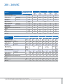
1
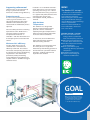
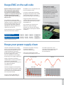
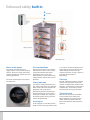
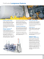
MAKING MODERN LIVING POSSIBLE VLT® HVAC Drive For HVAC it has to be VLT® 1.5 mio VLT® HVAC Drives reliably perform tasks in HVAC systems. Rely on proven VLT® technology – now available PM motor control, offering efficient control of EC and IEC standard motors types. 56% Energy use reduction in Mumbai’s VSNL building. ‘Only by using Variable Frequency Drives in the HVAC system could we achieve this target’ – General Manager VSNL, India. www.danfoss.com/drives VLT® HVAC Drive provide the lowest life-time cost The VLT® HVAC Drive is the safe choice for fan, pump or compressor applications. It provides a high flexibility with regard to the place of installation, range of available bus systems, broadest HVAC control intelligence and functionality, and respecting the building environment by offering the best EMC and harmonics behaviour in the market. nent magnet motors. It can log and record it’s own energy load profile for both estimation and validation of actual energy savings. The HVAC Drive offers the highest efficiency solution with both asynchronous motors and perma- In everything we do, Danfoss is a clean tech company. The VLT® HVAC Drive includes: ■ > 98% basic energy efficiency ■ Automatic Energy Optimisation ■ User-friendly operation ■ Programming in 27 languages ■ VLT® quality up to 1.4 MW 2 The VLT® HVAC Drive is a singular engineering platform for all your variable speed needs designed to minimize the total applied system cost and lifecycle cost. Save money Easy commissioning The modular design enables the user greater flexibility to select from a range of functional performance requirements to secure the best cost advantage for their application needs. ■ ■ ■ ■ Application menus Quick menu Motor Rotation Check PID-auto tuning High ambient temperature Fire Override Mode EMC & network protection The robust VLT® HVAC Drive is designed to work at maximum output in an ambient temperature up to 50° C. At higher temperatures, the drive will continue operation with lower performance. Automatic derating enables reduced operation for a period of time still at higher ambient temperatures to maintain operation of the HVAC system. Fire Override Mode helps keep fire escape routes free of smoke, overrides the drive’s self-protecting features and keeps the driven equipment running as long as possible in the event of fire. Fully integrated EMC filters eliminate the cost of installing external EMC filters and secure the highest integrity & fully tested EMC performance. Activating Fire Override Mode will ensure the VLT® HVAC Drive ignores “soft“ faults and alarms to continue operation during essential services such as a “fire” command. Maintenance free Save cabinet All versions of VLT® HVAC Drive comply as standard with EMC limits according to the EN 61800-3 norm (page 13). All A1 and B filter options are available as factory built-in options. Due to a series of self-protecting and monitoring features and a highly durable mechanical design, the VLT® HVAC Drive is maintenance free, except for general cleaning. No replacement of internal fans or capacitors is required. We offer a standard & integrated IP55/ Type 12 protection class equal to that of the motor. The standard integrated DC coils also ensure low harmonic load on the network within EN 61000-3-12 and increase the lifespan of the DC link capacitors. They also ensure that the drive can operate motors to their full performance. This eliminates the cost of a separate enclosure and saves on the additional installation costs associated with installation in a remote location. Save space IP 66/Type 4x Indoor for harsh environments Due to its compact dimensions, the VLT® HVAC Drive is easily mounted inside a HVAC unit or panel, reducing overall enclosure costs and freeing up panel backspace for other devices. For further protection against harmonic disturbances of the supply grid, Danfoss provides passive solutions such as 12/18 pulse solutions and Advanved Harmonic Filters (AHF). IP 66/Type 4x enclosure option for harsh environments also can eliminate the cost of a separate enclosure and reduce the installation costs associated with remote installations. Save energy Active solutions Danfoss also provides active solutions such as Low Harmonic Drives, combining standard drives with an active filter and standalone VLT® Advanced Active Filters (AAF). The energy consumption from HVAC applications such as fans and pumps raises with the cube of the flow. Thats the reason why VLT® control of such applications typically save 48% energy compared to on-off operation Proven reliability The first VLT® HVAC Drive – the VLT® 100 from 1983 – has proven the reliability of VLT® drives. Original VLT® HVAC Drives installed in1983 are still functioning reliably over 20 years later. VLT® Integrated Servo Drive VLT® Decentral Drive FCD 302 Global Marine VLT® VLT® OneGearDrive 12-Pulse Drive VLT® Micro Drive VLT® 5 VLT® 100 VLT® 1000 VLT® 3000 HVAC VLT® 2000 VLT® 3500 HVAC 1968 1983 1988 1989 1993 VLT® 5000 VLT® 5000 book VLT® 6000 HVAC 1996 VLT® Drive Motor FCM 300 1998 VLT® 2800 VLT® FCD 300 2000 VLT® AutomationDrive VLT® HVAC Drive VLT® AQUA Drive 2004 VLT® High Power Drives 2006-2008 VLT® Advanced Active Filter VLT® High Power Drives up to 1.4 MW 2010-2011 2013- 3 VLT® HVAC Drives make your building green Expect optimisation Danfoss’ long experience in applying drives in HVAC systems has enhanced its ability to offer a “Best in Class” technical expertise in integrating the drive into the overall system design to extract the maximum value from your initial investment and optimize the operational savings performance. The 21st Century focus on energy efficiency is not new with regards to energy saving but the emphasis on the consequences of wasted energy and the over-use of fossil fuels to produce energy is at the top of the agenda. Climate Change is seen as a cost to the human race more than simply a financial cost. Save energy and CO2 emission VLT® frequency converters save more than 20 million MWh of energy 4 globally each year. This is equivalent to the annual electricity consumption of 5 million homes. This energy saving reduce the annual CO2 emissions with 12 million tons! Makes the building perform Today the prime focus is on the overall performance of buildings including design, construction, efficiency, sustainability and the environmental impact of these buildings in the future. Energy efficient products form part of this overall plan. In most countries around the world this is now realized in the evaluation of high performance buildings under the banner LEED. We offer you a wealth of knowledge The various applications incorporated within high performance buildings are well understood by Danfoss and as global market leader we have built a wealth of knowledge and understanding of the applications and developed products and technology to ensure we meet and determine future trends in this industry. Our 40 years of experience in this business has made the VLT® HVAC Drive the industry benchmark. Premier drive in the market The efficiency of the VLT® HVAC Drive and its built-in features make the VLT® HVAC Drive the premier drive in the market today. Danfoss application and industry knowledge will ensure that the investment made in VLT® drives provides a qualified return. Financial incentives are just as important as moral incentives to make people choose energy efficient solutions. Reliable and cost effective Correct drive selection is critical to reliability. Products that introduce unacceptable levels of RFI or harmonics into a building can prove highly problematic and costly in addition to breaking legislative regulations. Danfoss’ many years of experience in the application of VLT® drives and in the HVAC industry in particular, has resulted in a global team focused on delivering the best drives solution, ensuring total security of your investment. Minimum impact on the environment Having chosen to fit a VLT® drive as part of the building control architecture, the lifetime sustainability of this product is an important aspect. end-of-life? Danfoss complies with RoHS, WEEE Directives, ISO14001 are all standards and directives created to ensure the minimum impact on the environment. Energy monitoring New regulations are forcing manufacturers to look at how they manufacture, what they manufacture and with what materials. Are products harmful to make? Are they harmful to dispose of at their The VLT® HVAC Drive provides a complete range of energy consumption information. Choose to divide absolute energy consumption into hours, days or weeks or to monitor a load profile for the application. Energy documentation VLT® Energy Box software is the most modern and advanced energy calculation tool available. It allows energy consumption calculations and comparisons of HVAC fans, pumps and cooling tower applications driven by Danfoss drives and alternative methods of flow control. The program compares the total operation costs of various traditional systems to operation of the same system with a VLT® HVAC Drive. With this program it is easy to evaluate the savings by comparing a VLT® HVAC Drive over other types of capacity control systems in both new installations as well as retrofit situations. Complete financial analysis VLT® Energy Box provides a complete financial analysis including: ■ ■ ■ ■ Initial cost for the drive system and the alternative system Installation and hardware costs Annual maintenance costs and any utility company incentives for energy conservation products Payback time and accumulated savings ■ Upload of actual energy consumption (kWh) and duty cycle from the VLT® HVAC Drive VLT® Energy Box makes it possible to capture actual energy data from the drives and monitor energy consumption and overall system efficiency. Audit equipment for both estimation and validation of savings. VLT® HVAC Drive can be interrogated remotely for full energy data, making it easy to monitor your energy savings and return on investment. Monitoring via fieldbus often makes energy meters omissible. Energy audit The VLT® HVAC Drive coupled with Energy Box software enables the package to be used as the Energy 5 Danfoss VLT® HVAC Drive provide lowest cost of ownership ness and highest efficiency in daily operations with environmental sustainability. Total Cost of Ownership is an organization’s total cost of acquiring, operating and maintaining a system through a given lifecycle. Danfoss dedicated HVAC organization at your side Total Cost of Ownership includes initial acquisition cost and operating cost. Through its technology and experience, Danfoss can transform this into the “Benefit of Ownership”. Customer assurance stems from Danfoss’ dedicated and highly experienced HVAC support team. It has the depth of understanding in HVAC applications that ensures the maximum benefit is extracted from the customers’ investment in VLT® drive systems. We understand the needs of our customers operating their facilities in a competitive environment which requires total system cost effective- Total lifetime cost Disposal Cost Energy Commissioning and installation Purchase Time 6 Reducing acquisition costs ■ Fully integrated EMC & Harmonic compliant solution ■ IP 21/55/66; Type 1/12/4x ■ Extensive HVAC functions to reduce other system components ■ Extendable I/O to reduce total BMS costs ■ Ease of installation and set-up Reducing operating costs ■ ■ ■ ■ ■ ■ ■ ■ ■ ■ ■ Minimum 98% efficiency Energy metering Automatic Energy Optimisation Design lifetime of 10 years Danfoss legacy and history in HVAC applications IP enclosures and optional conformal coating to provide robust & reliable performance in the harshest of environments 50° C ambient temperature without derating Auto derate functions above 50o Broadest range of drive and motor protection Maintenance free drive System diagnostics Enhanced advanced monitoring Enhanced advanced application monitoring functionality for fans allows you to keep track of the status of pumps and compressors. This can mean increased lifetime, reduced maintenance costs, and less downtime. Supporting software tool Software tools are available to help design a system with minimal harmonics and best energy efficiency. Protection mode As soon as the system detects a critical status (e.g. over-current or overvoltage) the frequency of the VLT® HVAC Drive will automatically be reduced and the modulation process adjusted. Due to its ability to limit its switching operations the VLT® HVAC Drive is extremely reliable and robust. The protection mode will – if allowable – end after 10 seconds and the frequency will be restored under control. Installed in an air conditioned switchroom, lower losses can easily result in operating cost savings >5% – 10% of the cost of the drive every year (based on a typical load profile, with the drive operating 24/7). Also energy consumption and CO2 emission is reduced. High Ambient Temperatures VLT® HVAC Drive is designed to operate in ambient temperatures up to 50o C with an autoderate capability for higher temperatures in order to maintain reduced operation in extreme climate conditions. In most cases, the VLT® HVAC Drive will handle abnormal situations without needing attention. Minimum 98% efficiency The VLT® HVAC Drive sets new standards with a minimum 98% efficiency at full load. This reduces initial costs and operating costs due to the smaller heat load/air conditioning requirement in the switchroom/ plantroom, thereby maximizing energy efficiency. Every kW of losses requires another ~0.5 kW of energy to remove the heat. VLT® HVAC Drive will manage the loss of a mains phase or a high mains imbalance by autoderating speed and load to maintain a period of reduced operation, enabling technicians to respond to the situation. NEW! The Danfoss EC+ concept... ... enables the use of PM motors in IEC-standard sizes with Danfoss VLT® frequency converters. After entering the relevant motor data, you benefit from the high engine efficiency at EC technology level in all applications. Necessary control method has been embedded in dedicated VLT® series drives. Benefits of the EC + concept: ■ Free choice of motor technology: PM or asynchronous with same frequency converter ■ Operation and installation of the VLT® drive remain the same ■ Vendor-independent election of all components ■ Best system efficiency by combining efficiency-optimized components ■ Retrofit of existing plant ■ Support a broad range of standard and PM motors GOAL efficiency Our goal is the highest efficiency with the lowest energy consumption and with the lowest overall system cost for our customers = “The Benefit of Ownership”. 7 The modular VLT® HVAC Drive – not too much – nor too little The VLT® HVAC Drive is built on Danfoss’ modular concept. Real plug-and-play adding and exchanging of options. Just upgrade instead of buying a new drive. 1 – – – – – 8 Fieldbus option Advanced BACnet LonWorks Profibus PROFINET DeviceNet 5 1 2 3 2 Local Control Panel (LCP) Choose numerical, graphical or no display 9 4 3 I/O option – General Purpose I/O (3DI + 2AI + 2DO + 1AO) – Analog I/O option (3AI (0 – 10 V / PT1000 / NI 1000) + 3AO (0 – 10 V)) – Relay output (3 x relays) 4 24 V supply option 5 RFI filter Built-in RFI filter for long motor cables compliant with the IEC 61800-3 and EN 55011 standards. 7 The modular design of the VLT® HVAC Drive allows even highly customised drives to be mass produced and factory tested. Plug-and-play options make upgrading easy and ensure flexibility. 6 8 6 AC mains disconnect (Factory mounted option) 7 Input mains option Various input plate configurations are available including mains switch (disconnect), or RFI filter. Input plates are field adaptable if options need to be added after installation. Unique cooling concept – No ambient air flow over the electronics up to 90 kW – Above 90 kW, designed with back channel cooling (85% heat dissipated via back channel) 9 Durable in aggressive environments In some HVAC applications, it is recommended to protect the drive with coated PCB’s. VLT® HVAC Drive is designed for level 3C2 according to IEC 60721-3-3. Protection level 3C3 is optionally delivered from factory. This option offers significantly improved protection against chlorine, hydrogen sulphide, ammonia and other corrosive environments. 8 VLT® quality up to 1.4 MW The VLT® HVAC Drive is available from 1.1 kW to 1.4 MW. Drive experience since 1968 lies behind the intelligent design of VLT® drives. All enclosures are mechanically designed with focus on: – Robustness – Easy access and installation – Intelligent cooling – High ambient temperatures The VLT® HVAC Drive is hooked upon your net The VLT® HVAC Drive integrates and communicates seamlessly with all HVAC devices, mastered by Building Management Systems via the fieldbus. HVAC-specific features make it economical, flexible and user-friendly and make HVAC operation simple. With VLT® HVAC Drive it is possible to read all the inputs and control all the outputs on I/O options. This means that when integrating a VLT® HVAC Drive into the control system it is possible to save by requiring fewer physical I/O points. Improve system performance VLT® HVAC Drive uses limited network bandwidth, and it requires less resources in the DDC controller due to the support of alarm and event notification. This can reduce traffic by more than 50% compared to other drives. Detailed information about warnings and alarms VLT® HVAC Drive has points giving detailed information about alarms and warnings. DDC controllers can monitor these and see when an alarm or warning occurs and why it occurred. Embedded fieldbuses ■ ■ ■ ■ ■ Native BACnet Modbus RTU (std.) FC protocol N2 Metasys FLN Apogee Optional fieldbuses ■ ■ ■ ■ Advanced BACnet LonWorks Profibus Devicenet NEW! ■ Ethernet Have BACnet your way VLT® HVAC Drive comes with an embedded BACnet protocol that makes it suited for most smaller plants. For larger plants, more system performance is required. The VLT® BACnet option is a plug-andplay solution that optimizes the use of VLT® HVAC Drive together with building management systems using the BACnet® fieldbus. Listed by BTL The option has passed comprehensive and long-lasting tests at the BTL laboratories, which ensures that the function will work together with any other BLT-listed equipment. VLT® HVAC Drive has objects defined to accept 3 separate feedbacks transmitted over BACnet. This option makes it easy to control or monitor points required in typical HVAC applications. 9 VLT® HVAC drives – optimized for installation in panels IP 20/Type 1 enclosures The installation volume and/or the mounting surfaces are reduced by up to 60% compared to the previous series. The functional sections nevertheless fulfill the highest requirements even for applications with high overload, long motor cables and ambient temperatures up to 50° C (55° C with derating). Optimized design Optimized efficiency and intelligent cooling technology make for a compact and service-friendly design. Supplementary equipment such as EMC filters, harmonics suppression and brake modules are integrated into the enclosure. Save installation time The IP20/NEMA 1 series is designed for easy accessibility and time-saving installation. Mechanical fastening points are easy to access from the front even with automatic tools. All terminals are sufficiently dimensioned and clearly marked. One needs only loosen a few screws to get to the terminals. Accessories for bonding screened cables are included. The compact enclosures are easier to install. This is important especially within existing installations with limited accessibility. An extensive range of options and accessories are available, optimizing the drive for the respective application. Intelligent heat management – variable cooling methods for different benefits Total separation between cooling air and electronics protects the electronics and allows for solutions where heat is removed from outside of the cabinets. With the VLT® HVAC Drive, a flanged heat sink kit is available for mounting the drive in the backplate of a cabinet, separating the heatsink airflow from the electronics. Eliminating airflow over the electronics increases lifetime as contaminants are excluded from the drive. Back channel cooling minimizes heat loss increasing energy efficiency, a significant benefit for high power drives. 10 High reliability in any environment All VLT® HVAC Drive versions have manganese phosphor rear bodies. IP66/Type 4x enclosed drives are suitable for installation in demanding environments (e.g. cooling towers). Cooling air is kept outside the device to prevent any pollution of the electronics. The surfaces are smooth and can easily be cleaned. The IP55/66, Type 4x series are designed for easy accessibility and time-saving installation. Furthermore, all components such as EMC filters for compliance with EN 55011, class A1/B, as well as the DC coils, are protected inside the drive. NEW! Type 4x Indoor VLT® HVAC Drive comes in the extremely tight Type 4x enclosure. Because of the high-density integration, the tight housings of the VLT® HVAC Drive are significantly smaller when compared to other drives of the same performance. Motor and power cables are mounted securely through glands in the base plate. The VLT® HVAC Drive is also available with a mains switch option. This switch interrupts the mains supply and has a free useable auxiliary contact. An external watertight USB plug connected to the control card inside IP 55/66 enclosures makes USB access easy. 11 The real effect of VLT® HVAC drives is – money-saving right through the chain Automatic Energy Optimisation The standard feature AEO provides optimized motor magnetization at all speeds and loads. This optimization program increases the energy savings gained by applying variable speed control. Automatic Motor Adaptation Enter the name plate data, and VLT® HVAC Drive automatically adjusts to the motor. Suitable for “follower” operation The drive’s modular structure makes it suitable for “follower” operation mastered by BMS, PLC’s or DDCs. 12 Automatic Energy Optimisation Start with high acceleration AEO-adjustment Speed Automatic load adjustment Motor voltage Motor current Keeps EMC on the safe side Optimum EMC protection coupled with integrated harmonic filters ensures that the optimum EMC environment and cleanest power supplies are maintained throughout the operational lifetime of the system, negating any reduction in lifecycle costs. VLT® HVAC Drive meets the EMC product standard EN 61800-3 without additional external components even when using long motor cables, and corresponds to the EMC guidelines 2004/108/EC, offering performance superior to other drives. Critical for practical use is compliance with the environment standard Categories according to EN 61800-3 Limits according to EN 55011 Clean power supply EN 61800-3, class C1 (residential) and Class C2 (industrial area). C2 ensures reliable plant operation through full compliance with all EMC requirements, product standards, prescribed warnings, and restrictions. Integrated chokes minimise the network effects dramatically and thus maintain operation within the limits of EN 61000-3-12. These chokes also make the VLT® HVAC Drive stable and highly dynamic even during short supply voltage drops or other poor network conditions. C1 C2 C3 C4 Class B Class A1 Class A2 Exceeding class A2 VLT® HVAC Drive introduces a minimum of RFI or harmonic pollution into the building and avoids problematic and, in some countries/regions, performance outside of their regulations. VLT® HVAC Drive is a reliable and cost effective investment. DC coils reduce harmonic noise and protect the drive. Also EMC filters are integrated (meets EN 55011 A2, A1 or B). Comparison of limits EN 55011/61800-3 Keeps your power supply clean Harmonic distortion on the supply grid is an increasing problem mainly caused by electronic power devices including frequency converters, drawing non-sinusoidal current from the mains supply. This creates harmonic distortion on the supply depending on the supply impedance. tool which can quickly and easily be downloaded from www.drives.danfoss.com. the software presents a clear overview of each project with data presented in both tabular and bar-chart formats. Data can be entered, stored and recalled project by project. At a click Typical without filter With AHF Without filter With AHF Danfoss’ Harmonic Calculation Software MCT 31 makes it possible to calculate the extent of these harmonics at the planning stage and can suggest mitigation countermeasures. Harmonic mitigation can be particularly valuable when the power supply is backed up with emergency generators, which have poorer tolerance to non-sinusoidal currents. Current standards (EN 50106) are included in the software analysis Harmonic disturbance with and without AHF filter. 13 The common approach to drive programming 1 – – – – – Graphical display International letters and signs Graphical display with bar-charts Easy overview 27 languages selection iF awarded design 4 1 2 Illumination – Relevant buttons are illuminated when active – LEDs indicate the status of the drive 5 2 Menu structure – Based on the well known matrixsystem in today’s VLT® drives – Easy shortcuts for the experienced user – Edit and operate in different set-ups simultaneously 3 – – – – – – Other benefits Demountable during operation Upload and download functionality IP 65/NEMA 4 rating when mounted in a panel door. (A remote mounting kit is available) Up to 5 different variables visible at a time Manual speed/torque setting 100% user defined information and size Three panel options: Graphical, numerical, blind cover. 14 5 3 6 Quick Menus – A Danfoss-defined Quick Menu – A user-defined Quick Menu – A Changes Made menu lists the parameters unique to your application – A Function Setup menu provides quick and easy set-up for specific applications – A Logging menu provides access to operation history 4 6 Intuitive functions – Info (“on board manual”) – Cancel (“undo”) – Alarm log (quick access) The user interface may be mounted remotely on a control panel fascia, eliminating the need for additional switches and instrumentation. The VLT® HVAC Drive is controlled locally via a control panel. This is plugged in directly or connected via a cable. The VLT® HVAC Drive can be remote-commissioned and monitored via a USB cable or fieldbus communication. Special software is available: Wizards, Data transfer tool, VLT® Set-up Software MCT 10, and Language changer. New! Smart Start Saves commissioning time Smart Start guides you through 10 basic steps for commissioning the VLT® drive and ensures a quick, safe and energy saving commissioning. Smart Start is activated at the first power up, after a factory reset, or from the quick menu. When activating the Smart Start feature, the drive will ask for information it needs to run the application. Smart Start will require following information: ■ Number of motors connected ■ Thermal protection, yes/no ■ Nominal motor frequency ■ Motor voltage ■ Total motor power ■ ■ ■ ■ ■ Total motor current Nominal motor speed Minimum reference Maximum reference Application: Fan, pump or compressor The Smart Start also asks if you want to apply the VLT® features Automatic Motor Adaptation (AMA and the Automatic Energy Optimisation (AEO). The Smart Start will be deactivated when the drive is programmed via bus or fieldbus and after a timeout. NOTE: The Smart Start will only be active if you choose the graphical control panel. VLT® Motion Control Tool The real effect is money saved Set-up software provides easy control of details as well as a general overview of drive systems, large or small. The tool handles all drives-related data. Explorer-like interface The MCT 10 software features explorer-like interface design and functionality to ease both use and learning of the facilities. More efficient service organisation ■ Scope & logging: Analyze problems easily ■ Read out alarms, warnings and fault log in one view ■ Compare a saved project with an on-line drive More efficient commissioning ■ Off-line commissioning offsite ■ Save/send/mail projects anywhere ■ Easy fieldbus handling, multiple drives in project file. Enables service organization to be more efficient Basic ■ Scope & Graph ■ Alarm history in saved projects ■ Graphical Timebased Actions, Preventive Maintenance and Basic Cascade Controller ■ Multiple fieldbus support Advanced ■ No limitation in number of drives ■ Motor database ■ Real-time logging from drive ■ Sensorless pump control On-line and off-line mode In the online mode, you work with the actual setup of the drives in question. Your actions will have immediate effect on the performance of the drive(s). Connections ■ USB ■ RS485 Project oriented In project mode you work with the drive parameters as a “virtual” set-up. This allows you to adjust the whole system before you implement it into the drives and put it in action. In project mode you can set the system up even before the drives are installed. A single command will update the whole system. In case a drive is exchanged, it is easily set up to perform exactly as its predecessor. 15 Enhanced safety built-in Fresh air in Speed Easy to open doors Differential pressure Mains switch option Fire Override Mode This switch interrupts the mains supply and has a free useable auxiliary contact. The mains switch ensures the safety of staff during maintenance and cleaning operations. Activating the function “Fire-mode” within the VLT® drive ensures secure and continued operation within applications such as stair-well pressurization, car park exhaust fans, smoke exhaust and essential service functions. The mains switch option also reduces assembly cost. Clearly indicated Fire mode is clearly indicated on the VLT® display to prevent any confusion. When set, the drive will override self protection and will continue operation despite the possibility of permanent damage in case of overheating or overload. The vital goal is to keep the motor running even if it means self-destruction. Drive bypass If a drive bypass is available, the VLT® HVAC Drive will not only sacrifice itself 16 in case of an extreme condition, but is able to bypass itself and connect the motor directly to mains. This will maintain operation as long as power is provided and the motor is functioning. Safe Stop The VLT® HVAC Drive comes standard with the safe stop functionality. The solution is approved by authorities for category 3 installations in accordance with EN 954-1. This feature prevents the drive from starting unintended. Thermistor card With the PTC Thermistor Card MCB 112 the Danfoss VLT® HVAC Drive offers improved surveillance of the motor condition compared to the built-in ETR function and thermistor terminal. Dedicated fan features User-friendly, distributed intelligence and reduced power consumption are beneficial for fan applications. Velocity-to-flow conversion The VLT® HVAC Drive is able to convert velocity pressure sensor values into flow values. Operators can therefore set the drive up to provide a fixed flow or fixed differential flow. This way both comfort and energy consumption are optimized. Using a pressure sensor instead of a flow sensor saves money. Extends BMS capacity When integrated into the BMS network, all the HVAC Drive I/O points are available as remote I/O to extend the capacity of the BMS. For example, room temperature sensors (Pt1000/ Ni1000) can be directly connected. With the VLT® Sensor Input Card option the motor is protected from overheating in the bearings and windings. The individual sensor temperature is visible as a read out in the display or by field bus. Resonance Monitoring Intelligent AHU functions The VLT® HVAC Drive handles logical rules and inputs from sensors, realtime functionality, and time-related actions. This enables the HVAC Drive to control a wide range of functions, including: ■ Weekend and working-day operations ■ Cascaded P-PI for temperature control ■ Multi-zone “3” control ■ Flow balancing between fresh and outlet air ■ Belt monitoring By pressing a few buttons on the Local Control Panel the drive can be set to avoid frequency bands at which connected fans create resonances in the ventilation system. This reduses vibration noise and wear on equipment. Stairwell Pressurisation In the event of fire, the VLT® HVAC Drive can maintain a higher level of air pressure in stairwells than in other parts of the building and ensure that fire escapes remain free of smoke. Lower AHU costs Fire Override Mode Fire Override Mode prevents the VLT® HVAC Drive from stopping for self-protecting reasons. In this mode it will continue vital fan operation regardless of control signals, warnings or alarms. The VLT® HVAC Drive is fitted with a built-in Smart Logic Controller and four auto tune PID controllers and can control air handling functions with fans, valves and dampers. The build ing management’s DDC tasks are redused and valuable data points (DP) are free for other use. 4 x PID controller (Individual set points/feed backs) ■ 1 PID for closed loop control of the motor connected to the drive ■ 3 PID for external closed loop control of HVAC equipment ■ Auto-tuning of all 4 PID loops ■ Eliminates the need for other controllers ■ Provides flexibility for the BMS and reduces the load on the central BMS The drive controller uses an input sensor that measures pressure, temperature, or other variables to change the speed on the motor connected to the VLT® HVAC Drive, by adjusting the output frequency to match the varying load. The additional 3 PID controllers can be used for external sensors (i.e. pressure, temperature, flow) to control heating/cooling coil valves, outside/return/exhaust dampers or other external HVAC components. 17 Dedicated pump features The VLT® HVAC Drive offers a vast number of pump-specific features developed in cooperation with OEMs, contractors and manufacturers around the world. 1 Vital water supply Vital water supply can be assured in the event of leakage or a broken pipe. For example overload is prevented by reducing drive speed – and supply is secured at lower flow. Sleep Mode In Sleep Mode the drive detects situations with low or no flow. Instead of continuous operation sleep mode boosts the system pressure and then stops to save energy. The drive starts automatically when the pressure falls below the lower set point. 1 18 2 3 2 Auto tuning of the PI controllers With auto tuning of the PI controllers, the drive monitors how the system reacts on corrections made by the drive, learns from it, and calculates the “P” and “I” values so that precise and stable operation is achieved quickly. This applies to each PI controller in the 4-menu sets individually. Exact P and I settings at start-up will not be necessary – which lowers commissioning costs. 3 Flow compensation Significant energy savings and reduced installation costs are provided by flow compensation in both fan and pump systems. A pressure sensor mounted close to the fan or pump provides a reference enabling pressure to be kept constant at the discharge end of the system. The drive constantly adjusts the pressure reference to follow the system curve. Dry Pump Protection and End of Curve relate to situations where the pump runs without creating the desired pressure – as when a well runs dry or a pipe leaks. In this situation the drive sets off an alarm, shuts off the pump, or performs another preprogrammed action. Embedded Pump Cascade Controller The Pump Cascade Controller distributes running hours evenly across all pumps, keeps wear and tear on individual pumps to a minimum and ensures that all pumps are in great shape. Dry Pump Protection and End of Curve 4 No/low flow An operating pump will normally consume more power the faster it runs – according to a curve determined by the pump and application design. The VLT® HVAC Drive will detect situations where the pump runs fast but is not fully loaded – and thereby not consuming adequate power. This is the case when water circulation stops, the pump runs dry, or when pipes leak. 4 Dedicated compressor features Premium torque control The VLT® HVAC Drive has been designed to offer flexible, intelligent control of compressors, making it even easier to optimize cooling capacity with constant temperature and pressure levels for water chillers, and other typical compressor applications in HVAC. Replace a cascade with a single compressor The VLT® HVAC Drive provides the same level of flexibility with one large compressor instead of a cascade of 2 or 3 smaller compressors. The VLT® HVAC Drive operates all compressors at a far more refined range of speeds than normal – even above nominal speed – meaning that one large compressor is sufficient. Alternatively use the built-in cascade controller to operate the lead compressor with variable speed, while using the VLT® HVAC Drive to manage on/off control of up to two additional compressors. Fewer starts and stops A maximum number of start/stop cycles within a given period of time can be set via the LCP or MCT10. Since start-up is the most critical part of compressor operation this extends compressor lifetime. Set point in temperature The VLT® HVAC Drive calculates the actual refrigerant temperature from the measured pressure and refines compressor operation accordingly using the built-in PID controller. Quick start-up The temperature setpoint for this calculation is set in degrees via the Local Control Panel or MCT 10 – and not as a pressure value. The VLT® HVAC Drive provides increased break away torque and can give 110% torque for 60 seconds in normal operation. The VLT® HVAC Drive offers a feature to open a bypass valve and let the compresser start quickly without load. Improving energy efficiency ... continuously Traditional commercial air conditioning systems are designed for efficient operation at peak load conditions, so systems are actually oversized about 85% of the time or more. Consequently at part load conditions, the systems has excess capacity, with significant and costly energy waste. Variable speed will contribute to a higher COP and lower energy consumption with load matched to actual demand while delivering a solid return on investment (ROI). 19 VLT® HVAC Drive projects 20 Dubai Metro Danfoss Drives deliver a total of 260 drives rated from 90 to 325 kW for the new metro in Dubai, United Arab Emirates, to operate exhaust fans and tunnel ventilation. Dubai Metro is projected to carry approximately 1.2 million passengers on an average day, and 355 million passengers per year. Tropical Islands Resort near Berlin, Germany A steady 25° C air temperature, 31° C water temperature, no rain, and a pleasant 40% to 60% humidity for the resort’s tropical plants. Everyone’s idea of perfect weather! All this is possible with a first class climate and water control system driven by VLT® HVAC Drives. Opera House in Sydney, Australia The Sydney Opera House is one of the architectural wonders of the world, and perhaps the best known building of the 20th century. In 2001, the NSW Government provided $69 million for several projects to improve the facilities and environment for performing arts companies, patrons and visitors. Danfoss provided the drives. Shanghai General Motors, China Shanghai General Motors Co Ltd. is a 50-50% joint venture between General Motors and the Shanghai Automotive Industry Corporation Group (SAIC).Shanghai GM has an annual production capacity of 200,000 vehicles. Danfoss provides the VLT® HVAC drives to maintain the production environment. Torre Mayor, Mexico City With its 55 floors and a height of 225 m the Torre Mayor is the highest building in Latin America. Danfoss drives control the heating and ventilation. Crowne Plaza Copenhagen Towers in Ørestad, Denmark Copenhagen’s latest luxury hotel, the elegant Crowne Plaza Copenhagen Towers in Ørestad, has been designed from the ground upwards with sustainability in mind. VLT® HVAC Drives are a natural part of the solution. Specifications (Basic unit without extensions) Main supply (L1, L2, L3) Analog output Supply voltage 200 – 240 V ±10% Supply voltage 380 – 480 V ±10% Supply voltage 525 – 600 V ±10% Supply voltage 525 – 690 V ±10% Programmable analog outputs 1 Current range at analogue output 0/4 – 20 mA 50/60 Hz Max. load to common at analogue output (clamp 30) 500 Ω Displacement power factor (cos ф) near unity > 0.98 Accuracy on analog output Max. error: 1% of full scale Switching on input supply L1, L2, L3 1–2 times/min. Supply frequency Harmonic disturbance Meets EN 61000-3-12 Output data (U, V, W) Output voltage 15 mA Max. load (24 V) 200 mA Unlimited 1 – 3600 sec. Programmable digital inputs 6* Changeable to digital output 2 (terminal 27, 29) Logic PNP or NPN Voltage level 0 – 24 V DC Maximum voltage on input 28 V DC Input resistance, Ri Approx. 4 kΩ Scan interval 5 ms * 2 can be used as digital outputs 2 Voltage or current 0 to +10 V (scaleable) 0/4 to 20 mA (scaleable) Max. error: 0.5% of full scale Pulse inputs Programmable pulse inputs 2 Max. terminal load (AC) on 1-3 (break), 1-2 (make), 4-6 (break) power card 240 V AC, 2 A Max. terminal load (AC) on 4-5 (make) power card 400 V AC, 2 A Min. terminal load on 1-3 (break), 1-2 (make), 4-6 (break), 4-5 (make) power card Vibration test Max. relative humidity 24 V DC 10 mA, 24 V AC 20 mA 0 – 24 V DC (PNP positive logic) Max. error: 0.1% of full scale Digital outputs Programmable digital/pulse outputs 2 Voltage level at digital/frequency output 0 – 24 V DC Max. output current (sink or source) 40 mA Maximum output frequency at frequency output 0 to 32 kHz Max. error: 0.1% of full scale IP: 00/20/21/54/5566 UL Type: Chassis/1/12/4x Outdoor 1.0 g (D, E & F-enclosures: 0.7 g) 5% – 95% (IEC 721-3-3; Class 3K3 (non-condensing) during operation Ambient temperature Max. 50° C wo. derating Galvanic isolation of all I/O supplies according to PELV Aggressive environment Designed for coated/uncoated 3C3/3C2 (IEC 60721-3-3) 2* * Utilize some of the digital inputs Accuracy on frequency output Programmable relay outputs Enclosure Analogue inputs Pulse input accuracy (0.1 – 1 kHz) Relay output Surroundings/external Analog inputs Voltage level Up to 115 kBaud 0–1000 Hz Digital inputs Accuracy of analog inputs Type “B” Max. load (10 V) Ramp times Current level 1.1 (Full Speed) USB plug RS485 interface Switching on output Voltage level USB interface 0 – 100% of supply voltage Output frequency Modes Control card Fieldbus communication Standard built-in: FC Protocol N2 Metasys FLN Apogee Modbus RTU BACnet (embedded) Optional: LonWorks (MCA 108) BACnet (MCA 109) Profibus (MCA 101) DeviceNet (MCA 104) Protection mode for longest possible up-time – Electronic thermal motor protection against overload – Temperature monitoring of the heatsink ensures that the frequency converter trips if the temperature reaches 95° C ± 5° C. – The frequency converter is protected against short-circuits on motor terminals U, V, W. – The frequency converter is protected against earth faults on motor terminals U, V, W. – Protection against mains phase loss Global Marine 21 Power, currents and enclosures IP 00/Chassis IP 20/Chassis IP 21/Type 1 A2 A2 A5 A5 A3 A3 B3 B1 B1 B1 B2 B2 B2 C1 C1 C1 C4 C2 C2 C2 B4 C3 D3 D1 D1 D4 D2 D2 400 450 500 570 630 730 850 945 1060 1260 1415 IP 54/55/Type 12 418 470 523 596 630 763 889 988 1108 1317 1479 IP 21/Type 1 54 73 86 108 131 155 192 242 290 344 B3 B1 B1 B1 B4 B2 B2 B2 C3 C1 C1 C1 C4 C2 C2 C2 F2/ F4 IP 54/Type 12 56 76 90 113 137 162 201 253 303 360 A3 A3 A5 A5 F2/ F4 With upgrade kit 690 V A3 A3 A5 A5 E1 E1 E2 550 V IP 00/Chassis IP 66/Type 12 6.1 9 11 18 22 27 34 41 52 62 83 100 131 IP 55/Type 12 6.4 9.5 11.5 19 23 28 36 43 54 65 87 105 137 IP 21/Type 1 2.4 2.7 3.9 4.9 IP 20/Chassis IP 55/Type 12 IP 66/Type 12 A4/A5 A4/A5 IP 54/Type 12 1530 IP 21/Type 1 1720 IP 20/Chassis 8.2 11 14.5 21 27 34 40 52 65 80 105 130 160 190 240 302 361 443 540 590 678 730 780 890 1050 1160 1380 >550 V 2.6 2.9 4.1 5.2 IP 55/Type 12 D3 D1 D1 D4 D2 D2 D4 D2 D2 E2 E1 E1 F1/F3 C4 C2 C2 C2 10 13 16 24 32 37.5 44 61 73 90 106 147 177 212 260 315 395 480 600 658 745 800 880 990 1120 1260 1460 A2 A2 ≤550 V F1/F3 C1 C1 C1 2.7 3.4 4.8 6.3 F2/F4 C3 B2 B2 B2 >440 V 3 4.1 5.6 7.2 F2/F4 B4 ≤440 V Amp. F1/F3 B3 B1 B1 B1 T7 525 – 690 V Amp. IP 00/Chassis IP 66 /Type 12 A3 A3 A5 A5 T6 525 – 600 V Amp. F1/F3 24.2 30.8 46.2 59.4 74.8 88 115 143 170 A2 A2 IP 55 / Type 12 6.6 7.5 10.6 12.5 16.7 T4 380 – 480 V A4/A5 Amp. 1.1 1.5 2.2 3 3.7 4.0 5.5 7.5 11 15 18 22 30 37 45 55 75 90 110 132 160 200 250 315 355 400 450 500 560 630 710 800 900 1000 1200 1400 IP 21 /Type 1 kW P1K1 P1K5 P2K2 P3K0 P3K7 P4K0 P5K5 P7K5 P11K P15K P18K P22K P30K P37K P45K P55K P75K P90K P110 P132 P160 P200 P250 P315 P355 P400 P450 P500 P560 P630 P710 P800 P900 P1M0 P1M2 P1M4 A4/A5 FC 102 IP 20 /Chassis T2 200 – 240 V IP 66/Type 4x Outdoor Dimensions [mm] H W D H+ W+ A2 A3 268 90 130 205 375 90 130 A4 390 200 175 A5 420 200 B1 B2 480 650 242 260 B3 399 165 249 475 165 B4 520 230 242 670 255 C1 680 308 310 C2 770 370 335 C3 C4 D1 D2 D3 D4 E1 E2 F1 F2 F3 F4 550 660 1209 1589 1046 1327 840 831 2324 2324 2324 2324 308 370 420 408 2197 1705 1569 1962 2159 2159 333 380 375 736 736 927 927 927 927 755 950 329 391 Note: H and W dimensions are with back-plate. H+ and W+ are with IP upgrade kit. D dimensions are without option. A or B for A2 and A3. 22 Ordering type code for VLT® HVAC Drive [1] FC-102 [2] – [3] – [4] – [5] – [1] Application 102 VLT® HVAC Drive FC 102 [2] Power Size P1K1 P1K5 P2K2 P3K0 P3K7 P4K0 P5K5 P7K5 P11K P15K P18K P22K P30K P37K P45K P55K P75K P90K See ratings data on page 22 P110 for power ratings P132 P160 P200 P250 P315 P355 P400 P450 P500 P560 P630 P710 P800 P900 P1M0 P1M2 P1M4 [3] AC Line Voltage T2 3 x 200/240 V AC (1.1 – 45 kW) T4 3 x 380/480 V AC T6 3 x 525/600 V AC (1.1 – 90 kW) T7 3 x 525/690 V AC (45 kW – 1.2 MW) [6] – [7] – [8] – [9] – [10] – [11] – X – SXX X – X – [4] Enclosure For cabinet mounting: E00 IP 00/Chassis (enclosure D3, D4) E20 IP 20/Chassis (encl. A2, A3, B3, B4, C3, C4) Standalone: E21 IP 21/Type 1 (encl. B1, B2, C1, C2, D1, D2, E, F) E54 IP 54/Type 12 (encl. D1, D2, E, F) E55 IP 55/Type 12 (encl. A5, B1, B2, C1, C2) E66 IP 66/Type 4x Outd. (encl. A5, B1, B2, C1, C2) Special designs: C00 [12] IP 00/Chassis (encl. E00 – air duct in stainless steel) P20 IP 20/Chassis (encl. B4, C3, C4 – Back Plate) E2M IP 21/Type 1 (encl. D1, D2 – protective cover) P21 IP 21/Type 1 (encl. as E21 – Back Plate) E5M IP 54/Type 12 (encl. D1, D2 – protective cover) P55 IP 55/Type 12 (encl. as E55 – Back Plate) [5] RFI Filter (EN 55011) H1 RFI-Filter Class A1/B (A, B, C) H2 RFI-Filter, Class A2 (A, B, C, D, E, F) H3 RFI -Filter Class A1/B (A, B, C) H4 RFI-Filter, Class A1 (D, E, F) H6 RFI-Filter for Marine HX No RFI-Filter (A, B, C, 525 – 600 V) [6] Braking & Safety X No brake IGBT B Brake IGBT mounted T Safe stop without brake U With brake and Safe Stop [13] [14] – [15] [16] [17] [18] – CX – X – XX – [9] Mains Input X No option 1 Mains disconnect 3 Mains disconnect and fuses 5 Mains disconnect, fuses and load sharing 7 Fuses A Fuses & load sharing terminals D Load sharing terminals [10] Cable X Standard Cable Entries O Metric Cable Entries US cable entries S [13] A Option (Fieldbus) AX No fieldbus option A0 MCA 101 – Profibus DPV1 A4 MCA 104 – DeviceNet AG MCA 108 – LonWorks AJ MCA 109 – BACnet [14] B Option (Application) BX No application option BK MCB 101 – General Purpose I/O BP MCB 105 – Relay Expansion B0 MCB 109 – Analog I/O MCB 102 – PTC Thermistor Card B2 [18] D Option (Control Power Backup Input) DX No DC input installed D0 MCB 107 24 VDC backup input Please beware that not all combinations are possible. Find help configuring your drive with the online configurator found under: driveconfig.danfoss.com [7] Display (Local Control Panel) X Blank faceplate, no LCP installed G LCP 102 – Graphic LCP installed N LCP 101 – Numeric LCP installed [8] Conformal Coating (IEC 721-3-3) X No conformal coating C Conformal coating on all PCBs Based on your selection, Danfoss manufactures the desired VLT® HVAC Drive. You will receive a fully assembled frequency converter, tested under full load conditions. 23 Connection examples The numbers represent the terminals on the drive 3 Phase power input DC-Bus (U) 96 91 (L1) 92 (L2) 93 (L3) 95 PE (V) 97 (W) 98 (PE) 99 Motor Switch Mode Power Supply 10Vdc 24Vdc 88 (-) 89 (+) 15mA +10Vdc 50 (+10 V OUT) + - (R+) 82 200mA + - Brake resistor (R-) 81 S201 S202 relay1 ON=0-20mA OFF=0-10V 03 ON 54 (A IN) 1 2 0-10Vdc 0/4-20 mA ON 53 (A IN) 0/4-20 mA 1 2 0-10Vdc 02 55 (COM A IN) 240Vac, 2A 01 relay2 12 (+24V OUT) 06 240Vac, 2A 13 (+24V OUT) P 5-00 18 (D IN) 24V (NPN) 0V (PNP) 19 (D IN) 24V (NPN) 0V (PNP) 20 (COM D IN) 27 (D IN/OUT) 24V (NPN) 0V (PNP) (COM A OUT) 39 24V S801 ON (D IN/OUT) Analog Output 0/4-20 mA Par. 6 - 50 1 2 0V 400Vac, 2A 04 (A OUT) 42 24V 29 05 ON=Terminated OFF=Open 5V 24V (NPN) 0V (PNP) 0V S801 0V 32 (D IN) 24V (NPN) 0V (PNP) 33 (D IN) 24V (NPN) 0V (PNP) RS-485 Interface (P RS-485) 68 RS-485 (N RS-485) 69 (COM RS-485) 61 (PNP) = Source (NPN) = Sink * 37 (D IN) * Safe Stop optional This diagram shows a typical installation of the VLT® HVAC Drive. Power is connected to the terminals 91 (L1), 92 (L2) and 93 (L3) and the motor is connected to 96 (U), 97 (V) and 98 (W). Terminals 88 and 89 are used for load sharing between drives. Analog inputs can be connected to 24 the 53 (V or mA), and for 54 (V or mA) terminals. These inputs can be set up as either reference, feedback or thermistor inputs. There are 6 digital inputs to be connected to terminals 18, 19, 27, 29, 32, and 33. Two digital input/output terminals (27 and 29) can be set up as digital outputs to show an actual status or warning. The terminal 42 analog output can show process values such as 0 - Imax. On the 68 (P+) and 69 (N-) terminals’ RS 485 interface, the drive can be controlled and monitored via serial communication. 200 – 240 VAC IP 20 (IP 21*)/Chassis(Type 1) IP 55 + IP 66 /NEMA 12 Typical Shaft Output Typical Shaft Output at 208 V Continuous Output Current (3 x 200 – 240 V) Intermittent [kW] [HP] [A] [A] P1K1 1.1 1.5 6.6 7.3 A2 A4 + A5 P1K5 1.5 2.0 7.5 8.3 Output Power (208 V AC) [kVA] 2.38 2.70 Enclosure Continuous Continuous Intermittent Max. pre-fuses Environment Estimated power loss at rated max. load Weight IP 20 IP 21 IP 55, IP 66 Efficiency P3K0 3 4.0 12.5 13.8 P3K7 3.7 4.9 16.7 18.4 3.82 4.50 6.00 4 (10) [A] [A] [A] 5.9 6.5 20 6.8 7.5 20 9.5 10.5 20 11.3 12.4 32 15.0 16.5 32 [W] 63 82 116 155 185 [kg] [kg] [kg] 4.9 5.5 13.5 0.96 4.9 5.5 13.5 0.96 4.9 5.5 13.5 0.96 6.6 7.5 13.5 0.96 6.6 7.5 13.5 0.96 Typical Shaft Output Typical Shaft Output at 208 V Continuous Output Current (3 x 200 – 240 V) Intermittent [kW] [HP] [A] [A] P5K5 5.5 7.5 24.2 26.6 B3 B1 P7K5 7.5 10 30.8 33.9 Output Power (208 V AC) [kVA] 8.7 11.1 Enclosure P2K2 2.2 2.9 10.6 11.7 [mm2] ([AWG]) Max. cable size (Mains, motor, brake) Max. Input Current (3 x 200 – 240 V) A3 A5 IP 20 (IP 21*)/Chassis(Type 1) IP 21/Type 1, IP 55 + IP 66/Type 12 Continuous B4 P11K 11 15 46.2 50.8 B2 P15K 15 20 59.4 65.3 16.6 21.4 C3 C4 C2 P18K 18.5 25 74.8 82.3 C1 P22K 22 30 88.0 96.8 P30K 30 40 115 127 P37K 37 50 143 157 P45K 45 60 170 187 26.9 31.7 41.4 51.5 61.2 120 (250 MCM) Max. cable size Mains, motor, brake [mm2] ([AWG]) 10 (7) 35 (2) 50 (1/0) (B4 = 35 (2)) 95 (4/0) Max. cable size mains With mains disconnect switch included [mm2] ([AWG]) 16 (6) 35 (2) 35 (2) 70 (3/0) Max. Input Current (3 x 200 – 240 V) Continuous Intermittent Max. pre-fuses Environment Estimated power loss at rated max. load Weight IP 20 IP 21, IP 55, IP 66 Efficiency [A] 22.0 24.2 63 28.0 30.8 63 42.0 46.2 63 54.0 59.4 80 68.0 74.8 125 80.0 88.0 125 104.0 114.0 160 130.0 143.0 200 185 (kcmil 350) 154.0 169.0 250 [W] 269 310 447 602 737 845 1140 1353 1636 [kg] [kg] 12 23 0.96 12 23 0.96 12 23 0.96 23.5 27 0.96 23.5 45 0.96 35 45 0.97 35 45 0.97 50 65 0.97 50 65 0.97 [A] * (A2, A3, B3, B4, C3 and C4 may be converted to IP21/Type 1 using a conversion kit. (Please see also items Mechanical mounting in Operating Instructions and IP 21/ Type 1 Enclosure kit in the Design Guide.)) 25 380 – 480 VAC IP 20 (IP 21*)/Chassis(Type 1) IP 55 + IP 66 /Type 12 Typical Shaft Output Typical Shaft Output at 460 V Continuous Output Current (3 x 380 – 440 V) Intermittent Continuous Output Current (3 x 441 – 480 V) Intermittent [kW] [HP] [A] [A] [A] [A] P1K1 1.1 1.5 3 3.3 2.7 3.0 P1K5 1.5 2.0 4.1 4.5 3.4 3.7 A2 A4 + A5 P2K2 2.2 2.9 5.6 6.2 4.8 5.3 Output Power (400 V AC) Continuous [kVA] 2.1 2.8 3.9 5.0 6.9 9.0 11.0 Output Power (460 V AC) Continuous [kVA] 2.4 2.7 3.8 5.0 6.5 8.8 11.6 Enclosure [mm2] ([AWG]) Max. cable size (Mains, motor, brake) Max. Input Current (3 x 380 – 440 V) Max. Input Current (3 x 441 – 480 V) Continuous Intermittent Continuous Intermittent Max. pre-fuses Environment Estimated power loss at rated max. load Weight IP 20 IP 55, IP 66 Efficiency P3K0 3 4.0 7.2 7.9 6.3 6.9 P4K0 4 5.0 10 11 8.2 9.0 P5K5 5.5 7.5 13 14.3 11 12.1 P7K5 7.5 10 16 17.6 14.5 15.4 4 (10) [A] [A] [A] [A] [A] 2.7 3.0 2.7 3.0 10 3.7 4.1 3.1 3.4 10 5.0 5.5 4.3 4.7 20 6.5 7.2 5.7 6.3 20 9.0 9.9 7.4 8.1 20 11.7 12.9 9.9 10.9 32 14.4 15.8 13.0 14.3 32 [W] 58 62 88 116 124 187 255 [kg] [kg] 4.8 13.5 0.96 4.9 13.5 0.97 4.9 13.5 0.97 4.9 13.5 0.97 4.9 13.5 0.97 6.6 14.2 0.97 6.6 14.2 0.97 Intermittent [kW] [HP] [A] [A] [A] [A] P11K 11 15 24 26.4 21 23.1 B3 B1 P15K 15 20 32 35.2 27 29.7 Output Power (400 V AC) Continuous [kVA] 16.6 22.2 26 30.5 42.3 50.6 62.4 73.4 102 123 Output Power (460 V AC) Continuous [kVA] 16.7 21.5 27.1 31.9 41.4 51.8 63.7 83.7 104 128 Enclosure IP 20 (IP 21*)/Chassis(Type 1) IP 21/Type 1, IP 55 + IP 66/Type 12 Typical Shaft Output Typical Shaft Output at 460 V Continuous Output Current (3 x 380 – 439 V) Intermittent Output Current (3 x 440 – 480 V) Continuous Max. cable size Mains, motor, brake [mm2] ([AWG]) Max. cable size mains With mains disconnect switch included [mm2] ([AWG]) Max. Input Current (3 x 380 – 439 V) Continuous Max. Input Current (3 x 440 – 480 V) Continuous Intermittent Intermittent Max. pre-fuses Environment Estimated power loss at rated max. load Weight IP 20 IP 21, IP 55, IP 66 Efficiency 26 A3 A5 B4 C3 B2 P18K 18.5 25 37.5 41.3 34 37.4 P22K 22 30 44 48.4 40 44 P30K 30 40 61 67.1 52 61.6 10 (7) C4 C2 P37K 37 50 73 80.3 65 71.5 C1 P45K 45 60 90 99 80 88 P55K 55 75 106 117 105 116 P75K 75 100 147 162 130 143 P90K 90 125 177 195 160 176 50 (1/0) (B4 = 35 (2)) 35 (2) 16 (6) (250 95 (4/0) 120 MCM)1) 35 (2) 185 70 (3/0) (kcmil 350) 133 161 146 177 118 145 130 160 250 250 [A] 22 24.2 19 20.9 63 29 31.9 25 27.5 63 34 37.4 31 34.1 63 40 44 36 39.6 63 55 60.5 47 51.7 80 66 72.6 59 64.9 100 82 90.2 73 80.3 125 96 106 95 105 160 [W] 278 392 465 525 698 739 843 1083 1384 1474 [kg] [kg] 12 23 0.98 12 23 0.98 12 23 0.98 23.5 27 0.98 23.5 27 0.98 23.5 45 0.98 35 45 0.98 35 45 0.98 50 65 0.98 50 65 0.99 [A] [A] * (A2, A3, B3, B4, C3 and C4 may be converted to IP21 using a conversion kit. Please contact Danfoss. (Please see also items Mechanical mounting in Operating Instructions and IP 21/ Type 1 Enclosure kit in the Design Guide.)) 1) With brake and load sharing 95 (4/0) 525 – 600 VAC Enclosure IP 20 Chassis IP 21/Type 1 IP 55, IP 66/Type 12 Typical Shaft Output Output Current Continuous (3 x 525 – 550 V) Intermittent (3 x 525 – 550 V) Continuous (3 x 525 – 600 V) Intermittent (3 x 525 – 600 V) Output Power Continuous (525 V AC) Continuous (575 V AC) A3 B3 A3 B4 C3 C4 B1 B2 C1 C2 A5 P1K1 P1K5 P2K2 P3K0 P4K0 P5K5 P7K5 P11K P15K P18K P22K P30K P37K P45K P55K P75K P90K [kW] 1.1 1.5 2.2 3 4 5.5 7.5 11 15 18.5 22 30 37 45 55 75 90 [A] 2.6 2.9 4.1 5.2 6.4 9.5 11.5 19 23 28 36 43 54 65 87 105 137 [A] 2.9 3.2 4.5 5.7 7.0 10.5 12.7 21 25 31 40 47 59 72 96 116 151 [A] 2.4 2.7 3.9 4.9 6.1 9.0 11.0 18 22 27 34 41 52 62 83 100 131 [A] 2.6 3.0 4.3 5.4 6.7 9.9 12.1 20 24 30 37 45 57 68 91 110 144 [kVA] 2.5 2.8 3.9 5.0 6.1 9.0 11.0 18.1 21.9 26.7 34.3 41 51.4 61.9 82.9 100 130.5 [kVA] 2.4 2.7 3.9 4.9 6.1 9.0 11.0 17.9 21.9 26.9 33.9 40.8 51.8 61.7 82.7 99.6 130.5 Max. cable size IP 20 (mains, motor, brake) [mm2] Max. cable size IP 21/55/66 (mains, motor, brake) [mm2] Max. cable size mains With mains disconnect switch included Max. Input Current Continuous (3 x 525 – 600 V) Intermittent (3 x 525 – 600 V) Max. pre-fuses Environment Estimated power loss at rated max. load Weight IP 20 IP 21, IP 55, IP 66 Efficiency [mm2] ([AWG]) ([AWG]) 4 (10) 10 (7) 4 (10) 10 (7) 4 (10) ([AWG]) 35 (2) 50 (1/0) 35 (2) 16 (6) 120 95 (250 (4/0) MCM) 50 (1/0) 150 95 (250 (4/0) MCM) 1) 35 (2) 185 70 (3/0) (kcmil 350) [A] 2.4 2.7 4.1 5.2 5.8 8.6 10.4 17.2 20.9 25.4 32.7 39 49 59 78.9 95.3 124.3 [A] 2.7 3.0 4.5 5.7 6.4 9.5 11.5 19 23 28 36 43 54 65 87 105 137 [A] 10 10 20 20 20 32 32 63 63 63 63 80 100 125 160 250 250 [W] 50 65 92 122 145 195 261 300 400 475 525 700 750 850 1100 1400 1500 [kg] [kg] 6.5 13.5 0.97 6.5 13.5 0.97 6.5 13.5 0.97 6.5 13.5 0.97 6.5 13.5 0.97 6.6 14.2 0.97 6.6 14.2 0.97 12 23 0.98 12 23 0.98 12 23 0.98 23.5 27 0.98 23.5 27 0.98 23.5 27 0.98 35 45 0.98 35 45 0.98 50 65 0.98 50 65 0.98 1) With brake and load sharing 95 (4/0) 27 380 – 480 VAC and 525 – 690 VAC High Power 380 – 480 VAC Enclosure IP 21/Type 1, IP 54/Type 12 IP 00/Chassis Typical Shaft Output at 400 V Typical Shaft Output at 460 V Output Current Continuous (at 400 V) Intermittent (60 sec overload) (at 400 V) Continuous (at 460/480 V) Intermittent (60 sec overload) (at 460/480 V) Output Power Continuous (at 400 V) Continuous (at 460 V) Max. Input Current Continuous (at 400 V) Continuous (at 460/480 V) Max. cable size Mains motor, brake and load share Max. external pre-fuses Estimated power loss at rated max. load – 400 V Estimated power loss at rated max. load – 460 V IP 21, IP 54 Weight IP 00 Efficiency Output Frequency Heatsink overtemp. trip Power card ambient trip D1 D3 [kW] [HP] P110 110 150 P132 132 200 P160 160 250 D2 D4 P200 200 300 [A] [A] [A] [A] 212 233 190 209 260 286 240 264 315 347 302 332 395 435 361 397 480 528 443 487 [kVA] [kVA] 147 151 180 191 218 241 274 288 333 353 [A] [A] [mm2] ([AWG]) [A] [W] [W] [kg] [kg] 204 183 251 231 304 291 463 427 300 3234 2947 96 82 350 3782 3665 104 91 630 5893 5634 151 138 85 90 400 4213 4063 125 112 0.98 0 – 800 105 60 381 348 2 x 150 (2 x 300 mcm) 500 5119 4652 136 123 105 115 2 x 70 (2 x 2/0) [Hz] [°C] [°C] P250 250 350 525 – 690 VAC Enclosure IP 21/Type 1, IP 54/Type 12 IP 00/Chassis Typical Shaft Output at 550 V Typical Shaft Output at 575 V Typical Shaft Output at 690 V Output Current Continuous (at 3 x 525 – 550 V) Continuous (at 550 V) Intermittent (60 sec overload) (at 550 V) Continuous (at 3 x 551 – 690 V) Continuous (at 575/690 V) Intermittent (60 sec overload) (at 575/690 V) Output Power Continuous (at 550 V) Continuous (at 575 V) Continuous (at 690 V) Max. Input Current Continuous (at 550 V) Continuous (at 575 V) Continuous (at 690 V) Max. cable size Mains, motor, load share and brake Max. external pre-fuses Estimated power loss at rated max. load – 600 V Estimated power loss at rated max. load – 690 V IP 21, IP 54 Weight IP 00 Efficiency Output Frequency Heatsink overtemp. trip Power card ambient trip 28 [kW] [HP] [kW] P45K 37 50 45 P55K 45 60 55 P75K 55 75 75 D1 D3 P90K 75 100 90 D2 D4 P110 90 125 110 P132 110 150 132 P160 132 200 160 P200 160 250 200 P250 200 300 250 162 178 201 221 253 278 303 333 [A] [A] [A] [A] [A] [A] 56 76 90 113 137 62 54 84 73 99 86 124 108 151 131 59 80 95 119 144 155 171 192 211 242 266 290 319 [kVA] [kVA] [kVA] 53 54 65 72 73 87 86 86 103 108 108 129 131 130 157 154 154 185 191 191 229 241 241 289 289 289 347 [A] [A] [A] [mm2] ([AWG]) [A] [W] [W] [kg] [kg] 60 58 58 77 74 77 110 106 109 130 124 128 158 151 155 125 1398 1458 160 1645 1717 200 2157 2262 250 2533 2662 89 85 87 2 x 70 (2 x 2/0) 200 1827 1913 96 82 0.97 [Hz] [°C] [°C] 198 189 197 2 x 70 (2 x 2/0) 315 350 2963 3430 3430 3612 104 91 0.98 245 299 234 286 240 296 2 x 150 (2 x 300 mcm) 350 400 4051 4867 4292 5156 125 136 112 123 0 – 600 85 90 60 110 Dimensions VLT® HVAC Drive In mm Min. 100 Exhaust A2 Enclosures 205 (220) 90 70 5,5 268 257 Exhaust Min. 100 Inlet 341 A2 Inlet 5,5 Rear View Depth 220 mm with A/B-Options 205 (220) 130 110 5,5 257 Exhaust 268 Exhaust Min. 100 A3 Enclosures Min. 100 Inlet 341 A3 5,5 Inlet Rear View Depth 220 mm with A/B-Options A4 Enclosures 176 ± 0.4 171 ± 0.4 420 ± 1 344.5 ± 0.4 397.5 ± 1 5 ± 0.2 A4 Rear View 29 Dimensions VLT® HVAC Drive In mm A5 Enclosures 200 215 242 402 Exhaust Min. 100 Inlet A5 420 Min. 100 Exhaust 6,5 6,5 Rear View Inlet B1 Enclosures 260 242 9 454 Min. 100 Inlet B1 480 Min. 100 Exhaust Exhaust 210 9 Rear View Inlet 30 Exhaust 9 624 Exhaust Min. 200 Inlet B2 260 650 242 Min. 200 B2 Enclosures 9 Inlet 210 Rear View Exhaust Min. 200 B3 Enclosures 165 249 (262) 6,8 140 Min. 200 Inlet 419 380 399 Exhaust 6,8 B3 Rear View Inlet Depth 262 mm with A/B-Options B4 Enclosures 231 Min. 200 Exhaust 242 8,5 200 Min. 200 Inlet 520 595 460 495 35 Exhaust B4 8,5 Rear View Inlet C1 Enclosures 308 310 272 9 C1 Min. 200 Inlet 680 648 Exhaust Min. 200 Exhaust 9 Rear View Inlet 31 Dimensions VLT® HVAC Drive In mm C2 Enclosures 335 370 9 Min. 225 Inlet 739 770 C2 334 Exhaust Min. 225 Exhaust Rear View 9 Inlet 36 8,5 270 Min. 200 Inlet Inlet 8,5 550 521 488 Exhaust 630 C3 308 334 Exhaust Min. 200 C3 Enclosures 210 Rear View Exhaust 334 8,5 36 370 330 631 660 Exhaust 598 Min. 225 C4 Enclosures Min. 225 Inlet 800 C4 8,5 Inlet Rear View 32 D1 Enclosures (Floor- or cabinet Mount) 420 74 Min. 22 Exhaust 765 m3/hr 170 m3/hr 1166 1209 D1 Min. 225 Inlet 981 310 163 380 417 Optional pedestal 176F1827 available for stand-alone floor mount installations (adds 200 mm to height) D2 Enclosures (Floor- or cabinet Mount) 420 72 Min. 225 Exhaust 765 m3/hr 1362 170 m3/hr 1589 1547 423 Min. 225 Inlet 157 D2 380 417 Optional pedestal 176F1827 available for stand-alone floor mount installations (adds 200 mm to height) Drives shown with optional disconnect switch 33 Dimensions VLT® HVAC Drive In mm D3 Enclosures (Cabinet Mount) 408 66 255 m3/hr Min. 225 Exhaust 765 m3/hr 1046 D3 997 818 Min. 225 Inlet 147 157 375 417 D4 Enclosures (Cabinet Mount) 66 408 255 m3/hr Min. 225 Exhaust 765 m3/hr 1327 D4 1280 1099 Min. 225 Inlet 161 151 375 417 34 Drives shown with optional disconnect switch VLT® HVAC Drive A Options Typecode Position VLT® LonWorks MCA 108 LonWorks is a fieldbus system developed for building automation. It enables communication between individual units in the same system (peer-to-peer) and thus supports decentralising of control. ■ ■ ■ ■ ■ ■ No need for big main station (master-follower) Units receive signals directly Supports Echelon free-topology interface (flexible cabling and installation) Supports embedded I/Os and I/O options (easy implementation of de-central I/Os) Sensor signals can quickly be moved to another controller via bus cables Certified as compliant with LonMark ver. 3.4 specifications 13 Ordering number 130B1106 uncoated – 130B1206 coated (Class 3C3/IEC 60721-3-3) VLT® BACnet MCA 109 The open communications protocol for worldwide building automation use. The BACnet protocol is an international protocol that efficiently integrates all parts of building automation equipment from the actuator level to the building management system. ■ ■ ■ ■ ■ ■ BACnet is the world standard for building automation International standard ISO 16484-5 With no license fees, the protocol can be used in building automation systems of all sizes The BACnet option lets the drive communicate with building management systems running the BACnet protocol Typical areas where BACnet is used include heating, ventilation, cooling and climate equipment control The BACnet protocol is easily integrated into existing control equipment networks 13 Ordering number 130B11446 uncoated – 130B1244 coated (Class 3C3/IEC 60721-3-3) VLT® DeviceNet MCA 104 ■ ■ This modern communications model offers key capabilities that let you effectively determine what information is needed and when You will also benefit from ODVA’s strong conformance testing policies, which ensure that products are interoperable Ordering number 130B1102 uncoated – 130B1202 coated (Class 3C3/IEC 60721-3-3) 13 VLT® PROFIBUS DP V1 MCA 101 ■ ■ ■ PROFIBUS DP V1 gives you wide compatibility, a high level of availability, support for all major PLC vendors, and compatibility with future versions Fast, efficient communication, transparent installation, advanced diagnosis and parameterisation and auto- configuration of process data via GSD-file A-cyclic parameterisation using PROFIBUS DP V1, PROFIdrive or Danfoss FC profile state machines, PROFIBUS DP V1, Master Class 1 and 2 Ordering number 130B1100 uncoated – 130B1200 coated (Class 3C3/IEC 60721-3-3) 13 Installation of options is a matter of plug-and-play 35 VLT® HVAC Drive B Options Typecode Position VLT® General Purpose I/O MCB 101 The I/O option offers an extended number of control inputs and outputs. 14 ■ ■ ■ 3 digital inputs 0-24 V: Logic ‘0’ < 5 V; Logic ‘1’ > 10 V 2 analogue inputs 0-10 V: Resolution 10 bit plus sign 2 digital outputs NPN/PNP push pull ■ ■ ■ 1 analogue output 0/4-20 mA Spring loaded connection Separate parameter settings Ordering number 130B1125 uncoated – 130B1212 coated (Class 3C3/IEC 60721-3-3) VLT® Relay Option MCB 105 Lets you extend relay functions with 3 additional relay outputs. 14 Max. terminal load: AC-1 Resistive load ..............................................240 V AC 2 A AC-15 Inductive load @cos ф 0.4 ...............240 V AC 0.2 A DC-1 Resistive load ...............................................24 V DC 1 A DC-13 Inductive load @cos ф 0.4 ..................24 V DC 0.1 A Min. terminal load: DC 5 V ................................................................................... 10 mA Max switch rate at rated load/min. load .............................................. 6 min-1/20 sec-1 Ordering number 130B1110 uncoated – 130B1210 coated (Class 3C3/IEC 60721-3-3) VLT® Analog I/O Option MCB 109 14 This analogue input/output option is easily fitted in the frequency converter for upgrading to advanced performance and control using the additional in/ outputs.This option also upgrades the frequency converter with a battery back-up supply for the clock built into the frequency converter. This provides stable use of all frequency converter clock functions as timed actions etc. ■ ■ 3 analogue inputs, each configurable as both voltage and temperature input Connection of 0-10 V analogue signals as well as PT1000 and NI1000 temperature inputs ■ ■ 3 analogue outputs each configurable as 0-10 V outputs Incl. back-up supply for the standard clock function in the frequency converter The back-up battery typically lasts for 10 years, depending on environment. Ordering number 130B1143 uncoated – 130B1243 coated (Class 3C3/IEC 60721-3-3) VLT® PTC Thermistor Card MCB 112 14 With the MCB 112 PTC Thermistor Card, the Danfoss VLT® HVAC Drive FC 102 now offers improved surveillance of the motor condition compared to the built-in ETR function and thermistor terminal. ■ ■ ■ Protects the motor from overheating ATEX approved for use in potentially explosive atmospheres Uses Safe Stop function, which is approved in accordance with Cat. 3 EN954-1 VLT® Sensor Input Card MCB 114 14 The option protects the motor from being overheated by monitoring the bearings and windings temperature in the motor. The limits as well as the action are adjustable and the individual sensor temperature is visible as a read out in the display or by field bus. Installation of options is a matter of plug-and-play 36 • Protects the motor from overheating • Three self-detecting sensor inputs for 2 or 3 wire PT100/PT1000 sensors • One additional analogue input 4-20mA VLT® HVAC Drive D Options & LCP LCP D Typecode Position VLT® 24 V DC Supply Option MCB 107 The option is used to connect an external DC supply to keep the control section and any installed option active when mains power is down. ■ ■ ■ ■ ■ ■ ■ ■ Input voltage range.................. 24 V DC +/- 15% (max. 37 V in 10 sec.) Max. input current ........................................................2.2 A Max. cable length ......................................................... 75 m Input capitance load .............................................. < 10 uF Power-up delay ........................................................... < 0.6 s Easy to install in drives in existing machines Keeps the control board and options active during power cuts Keeps fieldbuses active during power cuts 18 Ordering number 130B1108 uncoated – 130B1208 coated (Class 3C3/IEC 60721-3-3) Graphical Local Control Panel LCP 102 ■ ■ ■ ■ ■ ■ ■ Multi-language display Status messages Quick Menu for easy commissioning Parameter setting and explanation of parameter function Adjustment of parameters Full parameter backup and copy function Alarm logging ■ ■ ■ ■ Info button – explains the function of the selected item on display Hand-operated start/stop, or automatic mode selection Reset function Trend graph 15 + 17 Ordering number 130B1107 Numerical Local Control Panel LCP 101 The numerical control panel offers an excellent MMI interface to the drive. ■ ■ ■ ■ ■ Status messages Quick menu for easy commissioning Parameter setting and adjustment Hand-operated start/stop function or automatic mode select Reset function 15 Ordering number 130B1124 LCP Panel Mounting Kit For easy installation of the LCP 101 and LCP 102 in e.g. a cabinet. ■ ■ ■ ■ ■ IP 65/Type 12 (front) Thumb screws for tool-free installation Incl. 3 meters of cables in industry quality (also available separately) With or without LCP operating unit Each time easy to install Ordering number 130B1113 (Incl. graphical LCP, fasteners, 3 m cable and gasket). Ordering number 130B1114 (Incl. numerical LCP, fasteners and gasket). Ordering number 130B1129 (LCP front mounting IP 55/IP 66) – Ordering number 175Z0929 (cable only). Ordering number 130B1170 (Panel Mouting Kit for all LCP w.o. cable). 16 Ordering number 130B1117 (Mounting kit for all LCP’s including fasteners, 3 m cable and gasket). Installation of options is a matter of plug-and-play 37 VLT® HVAC Drive Accessories Profibus Adapter Sub-D9 Connector The adapter makes linking of fieldbus connections pluggable. For use with option A. ■ ■ Option to use prefabricated Profibus cabling For retrofit Screw terminals Screw terminals as an alternative to the standard springloaded terminals. ■ Pluggable ■ Terminal name is described Ordering number 130B1116 IP 21/Type 12 Kit The IP 21/Type 12 (NEMA1) kit is used for installation of VLT® drives in dry environments. The enclosure kits are available for frame sizes A1, A2, A3, B3, B4, C3 and C4. ■ ■ Supports VLT® drives from 1.1 to 90 kW Used on standard VLT® drives with or without mounted option modules ■ ■ IP 41 on top side PG 16 and PG 21 holes for glands 130B1122 for frame size A2, 130B1123 for frame size A3, 130B1187 for frame size B3, 130B1189 for frame size B4, 130B1191 for frame size C3, 130B1193 for frame size C4 Kit for panel through mount Mounting kit for external cooling of the heatsink for appliances with A5, B1, B2, C1 and C2 housing. ■ ■ ■ ■ ■ The air conditioned installation space can be reduced. Additional cooling may be omitted No contamination of electronics by forced ventilation Facilitates integrated assembly Reduced cabinet depth/less space VLT® Brake Resistors Energy generated during braking is absorbed by the resistors, protecting electrical components from heating up. ■ ■ ■ Danfoss brake resistors cover the full power range. ■ Quick braking of heavy loads Braking energy is only absorbed into the brake resistor External mounting makes it possible to use the generated heat All necessary approvals are available USB Extension USB extension for IP 55 and IP 66 enclosures. Makes the USB connector available outside the drive. The USB extension is designed for mounting in a cable gland in the bottom of the drive, which makes PC communication very easy even in drives with high IP rating. Please refer to the product and design manuals for selection and dimensioning 38 USB extension for A5-B1 enclosures, 350 mm cable, ordering number 130B1155 USB extension for B2-C enclosures, 650 mm cable, ordering number130B1156 VLT® HVAC Drive Accessories VLT® Harmonic Filter AHF 005/010 Easy, effective harmonic distortion reduction by connecting the AHF 005/010 harmonic filter in front of a Danfoss frequency converter. ■ ■ AHF 005 reduces total harmonic current distortion to 5% AHF 010 reduces total harmonic current distortion to 10% ■ ■ ■ ■ Small compact housing that can be fitted into a panel Easy to use in retrofit applications User-friendly start-up – no adjustment necessary No routine maintenance required VLT® Sine-Wave Filters Sine-wave filters are placed between the frequency converter and the motor to optimise the motor power current. ■ ■ ■ It provides a sinusoidal phase-to-phase motor voltage. The filters reduce motor insulation stress, acoustic noise from the motor, and bearing currents (especially in large motors). ■ ■ ■ ■ Reduces motor insulation stress Reduces acoustic noise from the motor Reduces bearing currents (especially in large motors) Enables use of longer motor cables Reduces losses in the motor Prolongs service lifetime IP 20/Chassis; IP 21/Type 1 VLT® dU/dt filter VLT® dU/dt filters are placed between the frequency converter and the motor to eliminate very fast voltage changes. ■ The motor terminal phase-to-phase voltage is still pulse shaped but its dU/dt values are reduced. ■ These filters reduce stress on the motor’s insulation and are recommended in applications with older motors, aggressive environments or frequent braking which cause increased DC link voltage. IP 20/Chassis; IP21/Type 1 ■ ■ ■ ■ DC-DC coupling of multiple drives possible High efficiency through IGBT technology Simple operation Overload protection in regenerative operation SVCD – regenerative braking Transferring the generated power from a decelerating motor back into the power supply enables braking of virtually unlimited duration. ■ ■ Energy efficient braking Self-synchronisation Note: Missing numbers can be found in the design manual or can be delivered on request 39 What VLT® is all about Danfoss VLT Drives is the world leader among dedicated drives providers – and still gaining market share. Environmentally responsible VLT® products are manufactured with respect for the safety and well-being of people and the environment. All activities are planned and performed taking into account the individual employee, the work environment and the external environment. Production takes place with a minimum of noise, smoke or other pollution and environmentally safe disposal of the products is pre-prepared. UN Global Compact Danfoss has signed the UN Global Compact on social and environmental responsibility and our companies act responsibly towards local societies. EU Directives All factories are certified according to ISO 14001 standard. All products fulfil the EU Directives for General Product Safety and the Machinery directive. Danfoss VLT Drives is, in all product series, implementing the EU Directive concerning Hazardous Substances in Electrical and Electrical Equipment (RoHS) and is designing all new product series according to the EU Directive on Waste Electrical and Electronic Equipment (WEEE). Dedicated to drives Dedication has been a key word since 1968, when Danfoss introduced the world’s first mass produced variable speed drive for AC motors – and named it VLT®. Twenty five hundred employees develop, manufacture, sell and service drives and soft starters in more than one hundred countries, focused only on drives and soft starters. Intelligent and innovative Developers at Danfoss VLT Drives have fully adopted modular principles in development as well as design, production and configuration. Tomorrow’s features are developed in parallel using dedicated technology platforms. This allows the development of all elements to take place in parallel, at the same time reducing time to market and ensuring that customers always enjoy the benefits of the latest features. Rely on the experts We take responsibility for every element of our products. The fact that we develop and produce our own features, hardware, software, power modules, printed circuit boards, and accessories is your guarantee of reliable products. Local backup – globally VLT® motor controllers are operating in applications all over the world and Danfoss VLT Drives’ experts located in more than 100 countries are ready to support our customers with application advice and service wherever they may be. Danfoss VLT Drives experts don’t stop until the customer’s drive challenges are solved. Impact on energy savings One year’s energy savings from our annual production of VLT® drives will save the energy equivalent to the energy production from a major power plant. Better process control at the same time improves product quality and reduces waste and wear on equipment. DKDD.PB.36.B1.02 VLT® is a trademark of Danfoss A/S Produced by PE-MMSC 2011.05