1
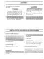
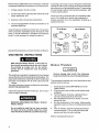
SEARS
GENERAL MANUAL
CRAFTSMAN
FOR
PERMANENTLY LUBRICATED
TANK MOUNTED
AIR COMPRESSOR
NOTE: For identificationof Repair
Parts, see separate Parts List
Manual.
Record in the spaces provided.
(1) The model number which can be
found on the maintenance label on
the top of the motor cover or on the
tank.
(2) The code number which can be
found on the small bar code label on
the rear of the air tank.
(3) The Manufacturers
Number is located on the metal data plate which
is welded onto the backside of the
air tank. (This data plate is painted
the same color as the tank.)
Retain these numbers for future
reference.
SAFETY GUIDELINES
i ASSEMBLY
;rOPERATION
i MAINTENANCE
i
IMPORTANT:
Read the Safety Guidelines
and All Instructions
Carefully Before Operating
i TROUBLESHOOTING
i REPAIR PARTS
Sears,
I MG1-OILFREE
9/17/941
Roebuck
Model No.
Code No.
Mfg. No.
and Co., Hoffman
Estates,
IL 60179
U.S.A.
TABLE
OF CONTENTS
Page
WARRANTY ...............................................................................................................................
2
SAFETY GUIDELINES
3
................................................................................................................
WARNING CHART ......................................................................................................................
3
GLOSSARY
5
...............................................................................................................................
ACCESSORIES
FOR USE WITH SEARS AIR COMPRESSORS
GENERAL INFORMATION
.................................................
..........................................................................................................
5
5
DESCRIPTION OF OPERATION ..................................................................................................
6
ASSEMBLY
7
...............................................................................................................................
INSTALLATION AND BREAK-IN PROCEDURES .........................................................................
Location of Air Compressor ...................................................................................................
Lubrication and Oil ................................................................................................................
Extension Cords ...................................................................................................................
Voltage and Circuit Protection ...............................................................................................
Grounding Instructions ..........................................................................................................
Break-in Procedure ...............................................................................................................
7
7
7
7
7
8
8
OPERATING PROCEDURES ......................................................................................................
9
MAINTENANCE .........................................................................................................................
Air Filter- Inspection and Replacement ................................................................................
CheckValve-Replacement
..................................................................................................
Safety Valve - Inspection ......................................................................................................
Motor ..................................................................................................................................
Storage ...............................................................................................................................
10
10
10
10
10
10
TROUBLESHOOTING GUIDE .....................................................................................................
11
HOWTO ORDER REPAIR PARTS .............................................................................................
16
FULL ONE YEAR WARRANTY
ON
AIR COMPRESSORS
If this air compressor fails due to a defect in material or workmanship within one year from the date of purchase, RETURN
IT TO THE NEAREST SEARS SERVICE CENTER/DEPARTMENT
THROUGHOUT THE UNITED STATES AND SEARS
WILL REPAIR IT, FREE OF CHARGE.
If this air compressor
of purchase.
is used for commercial
or rental purposes, the warranty will apply for ninety days from the date
This warranty gives you specific legal rights and you may have other rights which vary from state to state.
Sears,
Roebuck
and
Co.,
Hoffman
Estates,
IL 60179
U.S.A.
SAFETY GUIDELINES
This manual contains information that is important foryou to know and understand. This information relatesto protecting
YOUR SAFETY and PREVENTING EQUIPMENT PROBLEMS. To help you recognize this information, we use the
following symbols, Please read the manual and pay attention to these sections.
URGENT SAFETY INFORMATION
-A
HAZARD THAT WILL CAUSE
SERIOUS INJURY OR LOSS OF LIFE.
IMPORTANT
SAFETY INFORMATION
A HAZARD THAT MIGHT CAUSE
SERIOUS INJURY OR LOSS OF LIFE.
NOTE
Information
equipment.
for
HAZARDS
preventing
CAN
damage
OCCUR
PLEASE
WHAT TO
LOOK FOR
to
Information that you should pay special
attention to.
IF EQUIPMENT
READ
THE
IS NOT
FOLLOWING
WHAT COULD HAPPEN
HOW
USED
PROPERLY.
CHART.
TO PREVENT
IT
Hot Parts
The metal compressor components such as manifold, tubes, etc. become hot when the air compressor
is running. If you touch them, you may be seriously
burned.
Avoid contact with metal components of the compressor during or immediately after operation.
Reaching
under or removing portions of the plastic enclosures
such as the console cover exposes hot surfaces.
Allow compressor to cool prior to servicing.
Flammable
Vapors
It is normal for the motor and pressure switch to spark
when compressor starts or stops. A spark can ignite
vapors from gasoline or solvents, causing a fire or
explosion.
If spraying a flammable material, provide ample ventilation. Never spray in a closed area. There must be
a flow of fresh air at all times.
Always operate the air compressor in well-ventilated
areas, free of gasoline or other solvent vapors. Do not
operate the compressor near the spray area.
Air Tank
Modifications to air compressor components in an
attempt to reach higher air pressure can cause the air
tank to rupture or explode.
Do not adjust, remove or tamper with the safety valve
or pressure switch. If safety valve or pressure switch
replacement is necessary, a part with the same ratings must be used.
Incompatabitity between tank and compressor
cause the tank to rupture.
Never replace the air tank with a different model or a
larger tank.
Return to Authorized Service Center if
replacement is required.
will
Modifications to the air tank will cause it to weaken.
Never drill into, weld or in any way modify the air tank.
The tank may rupture or explode. If leaks develop due
to corrosion or tank is damaged, return to Authorized
Service Center for replacement.
SAFETY GUIDELINES
WHATTO
LOOK FOR
Compressed
Air
WHATCOULD
HAPPEN
Compressad air can propel dust, dirt or loose particles it comes in contact with. These propelled particles may cause serious injury or damage.
HOWTO PREVENT IT
Never point any nozzle or sprayer toward a person or
any part of the body.
Always wear safety goggles or glasses when using
the air compressor.
Always turn the air compressor
or removing accessories.
Too much air pressure applied to air tools or accessories can cause damage or risk of bursting.
Electricity
Your air compressor is powered by electricity. Like
any other electdca;_y powered device, if it is not used
properly it may cause electrical shock.
off before attaching
Check the manufacturer's pressure rating for air
tools and accessories. Regulator outlet pressure
must never exceed the maximum pressure rating.
Always unplug the air compressor
nance or repair.
Never use the air compressor
raining.
prior to mainte-
outdoors
when it is
Always plug the cord into an electrical outlet with the
specified voltage and adequate fuse protection.
Toxic
Vapors
It is normal for compressed air to contain toxic or
irritating vapors. Such vapors are harmful if inhaled.
Never directly inhale the compressed
this unit.
Certain materials you are spraying (like paint, weed
killer, sand or insecticide) can be harmful if you inhale
them.
Read labels and safety data for all materials you spray.
Follow all safety precautions.
air produced by
Use a mask or respirator if there is a chance of inhaling
toxic sprayed materials. Masks and respirators have
limits and will only provide protection against some
kinds and limited amounts of toxic material.
Read
mask and respirator instructions carefully.
Consult
with a safety expert or industrial hygienist if you are not
sure about the use of a certain mask or respirator.
Unsuitable
Solvents
The solvents 1,!,1 - Trichloroethane and Methylene
Chloride can chemically react with aluminum used in
paint spray guns, paint pumps, etc., and cause an
explosion. These solvents can also react with galvanized components and cause corrosion and weakening of parts. This does not affect your air compressor
- but it may affect the equipment being used.
If the material you intend to spray contains the solvents
listed at left (read the label or data sheet), do not use
accessories that contain aluminum or galvanized
parts. You must either change the material you intend
to spray, or use only stainless steel spray equipment.
GLOSSARY
CFM: Cubicfeet
perminute,
SCFM: Standard cubic feet per minute; a unit of measure
ofairdelivery.
PSIG: Pounds per square inchgauge; a unit of measure of
pressure.
AS ME: Amedcan Society of Mechanical Engineers; made,
tested, inspected and registered to meet the standards of
the ASME.
U.L. Listed: This product is Listed by Underwriters
Laboratories, Inc. (UL). Samples of this product have been
evaluated by UL and meet applicable UL Standards for
Safety.
Cut-In Pressure: While the motor is off, airtank pressure
drops as you continue to use your accessory. When the
tank pressure drops to a certain low level the motor will
restart automatically. The low pressure at which the motor
automatically re-starts is called "cut-in pressure."
Cut-Out Pressure: When you turn on your aircompressor
and it begins to run, air pressure in the air tank begins to
build. It buildsto a certain high pressure before the motor
automatically shuts off - protecting your air tank from
pressure higher than its capacity. The high pressure at
which the motor shuts off is called "cut-out pressure."
ACCESSORIES FOR USE WITH
SEARS AIR COMPRESSORS
•SPRAY GUNS
,BLOWGUNS
•AIR CAULKING GUNS
•PNEUMATIC POWER
WASHERS
.SANDBLASTERS
•AIR BRUSHES
•AIR LINE FI LTERS
"TIREAIRCHUCKS
°PAINTTANKS
"AIRTANKS
•INFLATOR KITS
•QUICKCONNECTOR SETS
(various sizes)
.VISCOSIMETER
•AIR PRESSURE REGULATORS
-OIL FOG LUBRICATORS
,AIRTOOLS:
Sanders
Drills
Impact Wrenches
Hammers
.AIRHOSE:
1/4", 5/16" or 3/8" I.D.
in various lengths
•NAI LER/STAPLERS
Decking
Farming
Roofing
Siding
Finishing
Carpentry
Upholstery
Picture Framing
•DRAIN CLEANER
-DUSTER GUN
GENERAL INFORMATION
You have purchased an air compressor unit consisting of a
one cylinder, single-stage air compressor pump and air
tank. included are an air hose, tire air chuck, wheels,
regulator, gauges, and handle.
This air compressor requires no oil. Nowyou can enjoy all
the benefits of having an air compressorwithout ever having
to purchase, add or change oil.
Your air compressorcan be used for operating paint spray
guns, air tools, caulking guns, grease guns, air brushes,
sandblaster, or inflating tires and plastic toys, spraying
weed killers, insecticides, etc. An air pressure regulator is
required for most of the applications.
An air filter which removes moisture and dirt from compressed air should be used where applicable.
These accessories can be purchased from most Sears
Parts Departments.
DESCRIPTION
OF OPERATION
Air Compressor Pump: To compress air, the piston
moves up and down in the cylinder. On the downstroke, air
isdrawn in through the air intake valves. Th e exhaust valves
remain closed. On the upstroke of the piston, air is
compressed. The intake valves close and compressed air
isforced outthrough the exhaust valves, through the outlet
tube, throughthe check valve and intothe airtank. Working
air is not available until the compressor has raised the air
tank pressure above that required at the air outlet.
Check Valve: When the air compressor is operating, the
check valve is"open", allowing compressed airto enterthe
air tank. When the air compressor reaches "cut-out"
pressure,the checkvalve "closes", allowing air pressureto
remain inside the air tank.
Pressure Release Valve: The pressure release valve located on the side of the pressure switch, is designed to
automatically release compressed air from the compressor
head and the outlet tube when the air compressor roaches
"cut-out" pressure or is shut off. Ifthe air is not released, the
motor will not be able to start. The pressure release valve
allows the motor to restart freely. When the motor stops
running, airwill be heard escaping from the valve for a few
seconds. No air should be leaking when the motor is
running.
Pressure Switch: The pressure switch automatically starts
the motor when the air tank pressure drops below the
factory set "cut-in" pressure. It stops the motor when the
airtank pressure reaches the factory set"cut-out" pressure.
Safety Valve: If the pressure switch does not shut off the
air compressor at its cut-out pressure setting, the safety
va lyewill protectthe tank against high pressure by"popping
out" at its factory set pressure (slightly higher than the
pressure switch cut-out setting).
Regulator." The air pressure coming from the air tank is
controlled by the regulator. Turn the regulator knob clockwise to increase pressure and counter-clockwise to decrease pressure. To avoid minor readjustment after making
a change in pressure setting, always approach the desired
pressure from a lower pressure. When reducing from a
higher to a lowersetting, first reduce to some pressure less
than that desired, then bring up to the desired pressure.
Depending on the air requirements of each particular
accessory, the outlet regulated air pressure may have to be
adjusted while operating the accessory.
Outlet Pressure Gauge: The outlet pressure gauge indicates the air pressure available at the outlet side of the
regulator. This pressure iscontrolled bythe regulator and
is always less or equal to the tank pressure. See "Operating Procedures".
Tank Pressure Gauge: The tan k pressure gauge indicates
the reserve air pressure in the tank.
Cooling System: This compressor contains an advanced
design cooling system. At the heart of this cooling system
is an engineered fan. It is perfectly normal forthis fan to blow
air through the vent holes in large amounts. You knowthat
the cooling system is working when air is being expelled.
Tools Needed for Assembly
• a 9/16" socket or open end wrench for attaching the wheels
• a 3/8" open end wrench or socket to tighten handle screws
ASSEMBLY
Installing
Wheels,
Handles,
Rubber
Foot Strip
It will be necessary to brace or support one
side of the outfit when installing the wheels
because the compressor will have a tendency to tip.
THE WHEELS AND HANDLE DO NOT PROVIDE ADEQUATE CLEARANCE, STABILITY
OR SUPPORT FOR PULLING THE UNIT UP
AND DOWN STAIRS OR STEPS. THE UNIT
MUSTBE LIFTED, OR PUSHED UPA RAMP.
.
.
Tighten securely. The outfit will sit level if the wheels
are properly installed.
Attach the handle to the compressor saddle by insertingthe handle inside the compressorsaddle and lining
up the two bolt holes on each side. Install the four
screws, two on each side. Tighten securely.
INSTALLATION
Location
Clean and dry underside of air tank leg opposite
wheels. Remove the protective paper strip from the
adhesive backed rubber foot strip. Attach the rubber
foot strip to the bottom of leg. Press firmly into place.
AND BREAK-IN
PROCEDURES
of the Air Compressor
Loca;.athe air compressorin a clean, dry and well ventilated
area. The airfilter must be kept clear of obstructionswhich
could reduce air delivery of the air compressor. The air
compressor should be located at least 12" away from the
wall or other obstructions that will interfere with the flow of
air. The air compressor head and shroud are designed to
allow for proper cooling.
Lubrication
•
a 3-wire extension cord that has a 3-blade grounding
plug, and a 3-slot receptacle that will accept the plug
on the product
•
in good condition
no Iongerthan 50 feet
•
12 gauge (AWG) or larger. (Wire size increases as
gauge number decreases. 10 AWG and 8 AWG may
also be used. DO NOT USE 14 OR 16 AWG.)
and Oil
This unit needs no lubrication or oiling.
Extension
Install one shoulder bolt and one nut for each wheel.
Cords
Use extra air hose instead of an extension cord to avoid
voltage drop and power loss to the motor, and to prevent
overheating.
Voltage
and Circuit
Protection
Referto your Parts List Manual forthe voltage and circuit
protction requirements of your compressor. Use only a fuse
or circuit breaker that is the same rating as the branch
circuit the air compressor is operated on. If the compressor
is connected to a circuit protcted by fuses, use only dual
RefertoPartsList Manual
for your compressor. Certain air
compressor models can be operated on a 15 amp circuit if:
1.
Voltage supply to circuit is normal.
2.
Circuit is not used to supply any otherelectdcal
(lights, appliances, etc.).
If repairing cord or plug, the grounding wire must be kept
separate from the current-carrying wires. Never connect the
grounding wire to a flat blade plug terminal. The grounding
wire has insulation with an outer surface that is green-with
or without yellow stripes.
needs
3.
Extension cords comply with specifications.
4.
Circuit is equipped with a 15 amp circuit breaker or 15
amp time delay fuse.
If these grounding instructions are not completely understood, or if in doubt as to whether the compressor is
properly grounded, have the installation checked by a
qualified electrician.
120 Volt Models
If any of the above conditions cannot be met, orif operation
of the compressor repeatedly causes interruption of the
power, it may be necessary to operate it from a 20 amp
circuit. It is not necessary to change the cord set.
240 Volt Models
wlllte
1,, p PLU
OUTL.
n G.ouNoED
20 AMP PLUG
OUTLET
o.oo.o,._,I
;element time delay fuses, as noted in that Service Bulletin.
GROUNDING
PIN
-7
PIN
GROUNDING
INSTRUCTIONS
RISK OR ELECTRICAL
SHOCK.
In the event of a
short circuit, grounding reduces the risk of shock
by providing
an escape wire for the electric
current. This air compressor
must be properly
grounded.
The portable air compressor is equipped with a cord having
a grounding wire with an appropriate grounding plug. The
plug must be used with an outlet that has been installed and
grounded in accordance with all local codes and ordinances.
The outlet must have the same configuration as the plug.
DO NOT USEAN ADAPTER.
Inspect the plug and cord before each use. Do not use if
there are signs of damage.
Break-in
Procedure
Serious damage may result if the following
break-in instructions are not closely followed.
This procedure is required only once, before the air compressor is put into service.
1.
2.
3.
4.
IMPROPER GROUNDING CAN RESULT IN ELECTRICAL SHOCK.
5.
Do not modify the plug that has been provided.
If it does not fit the available outlet, the correct
outlet should be installed by a qualified electrican.
6.
Set the pressure switch OFF/AUTO lever in the
"OFF" position.
Plug the power cord into the correct branch circuit
receptacle.
Turn the regulator clockwise, opening it fully, to
prevent air pressure build-up in the tank.
Movethe OFF/AUTO leverto"AUTO".
Thecompressor will start.
Run the compressor for 15 minutes. Make sure the
regulator is open and there is no tank pressure buildup.
After 15 minutes, close the regulator by turning it
counterclockwise. The air tank will fill to cut-out
pressure and then the motor will stop.
Refer to "Operating Procedures".
OPERATING
.
2.
PROCEDURES
Before attaching air hose or accessories, make sure
the OFF/AUTO lever is set to "OFF" and the air
regulator is closed.
Compressed air from the outfit may contain
water condensation.
Do not spray unfiltered air at an item that could be damaged.
Some air operated tools or devices may
require filtered air. Read the instructions
for the air tool or device.
.
.
Check the manufacturer's maximum pressure rating for air tools and accessories.
The regulator
outlet pressure must never exceed the maximum
pressure rating. If your compressor is not supplied
with a regulator with gauge, install one before
using accessories.
the compressor
When you are finished:
7.
Set the "OFF/AUTO"
8.
9.
near the spray
lever to "OFF".
Turn the regulator counterclockwise
let pressure to zero.
Remove the air tool or accessory.
and set the out-
10.
Open the regulator and allow the air to slowly bleed
from the tank. Close theregulator when tank pressure
is approximately 20 psi.
11.
Drain water from air tank.
WATER WILL CONDENSE IN THE AIR TANK.
IF NOT DRAINED, WATER WILL CORRODE
AND WEAKEN THE AIR TANK CAUSING A
RISK OF AIR TANK RUPTURE.
With tank pressure at approximately
drain cock or drain valve.
20 psi, open the
NOTE:
If drain cock valve is plugged, release all air
pressure.
The valve can then be removed,
cleaned, then reinstalled.
Turn the OFF/AUTO lever to "AUTO" and allow tank
pressure to build. Motor will stop when tank pressure
reaches "cut-out" pressure.
Open the regulator by turning it clockwise. Adjust the
regulator to the correct pressure setting. Your compressor is ready for use.
Always operate the air compressor in well-venti
lated areas; free of gasoline or other solvent
vapors.
Do not operate
area,
Attach hose and accessories,
TOO MUCH AIR PRESSURE CREATES
A HAZARDOUS RISK OF BURSTING.
CAREFULLY FOLLOW STEPS 3 AND 5
EACH TIME THE COMPRESSOR
IS
USED,
.
6.
12.
After the water has been drained, close
drain cock or drain valve. The air compressor
can now be stored.
MAINTENANCE
UNITCYCLESAUTOMATICALLYWHEN
POWERIS ON. WHEN DOING MAINTENANCE, YOU MAY BE EXPOSEDTOVOLTAGE
SOURCES, COMPRESSEDAIRORMOVING
PARTS. PERSONALINJURIESCANGCCUR.
BEFORE PERFORMINGANY
MAINTENANCE OR REPAIR, UN PLUG THE COMPRESSORAN D BLEED 0 FFALLAIR PRESSURE.
ALL MAINTENANCE
Air Filter-
Inspection
and
AND REPAIR OPERATIONS NOT LISTED MUST BE DONE BY
QUALIFIED SERVICE PERSONNEL.
Replacement
Hot surfaces. Risk of burn. Compressor
heads are exposed when filter cover
removed°
Allow compressor
to cool
prior to servicing.
Filte__
Safety
is
Valve
- inspection
If the safety valve does not work properly,
over-pressurization
may occur, causing air
tank rupture or an explosion.
Before starting compressor,
pull the ring on the safety
valve to make sure that the safety valve
operates freely. If the valve is stuck or does
not operate
smoothly,
it must be replaced
with the same type of valve.
Filter Retainer
Keep the air filter clean at all times. Do not operate the
compressorwith the air filter removed.
A dirty air filterwill not allowthe compressor to operate at
full capacity. Beforeyou usethe compressor, checkthe air
filter to be sure it is clean.
CheckYalve
- Replacement
Before servicing:
• Unplug or disconnect electrical
compressor.
•Bleed tank of pressure.
•Allow compressor to cool.
1.
2.
3.
4.
5.
supply to
Release all air pressure from airtank and unplug outfit.
Removeshroud.
Loosen the top and bottom nuts and remove the outlet
tube.
Removethe pressure releasetube and fitting.
Unscrewthe check valve (turn counterclockwise) using
a socket wrench.
6. Checkthatthevalve
disc moves freely insidethe check
valve and that the spring holds the disc in the upper,
closed position. The check valve may be cleaned with
a solvent, such as paint and varnish remover.
7. Apply sealant tothe check valve threads. Reinstall the
checkvalve (turn clockwise).
8. Replace the pressure release tube and fitting.
9. Replace the outlet tube and tighten top and bottom
nuts.
10. Replace the shroud.
10
Motor
The motor has an automatic reset thermal overload
protector, tf the motor overheats for any reason, the
overload protectorwill shut offthe motor. The motor
must be allowed to cool down before restarting. The
compressor will automatically restart after the motor
cools.
If the overload protectorshuts the motor off frequently,
check for a possible voltage problem. Lowvoltage can
also be suspected when:
1.
The motor does not get up to full power or speed.
2.
Fusesblowout
whenstartingthemotor;lightsdim
Storage
Before you store the air compressor, make sure you do
the following:
t.
2.
Reviewthe"Maintenance"and"Operating
Procedures" sections and perform maintenance as necessary. Be sure to drain water from the air tank.
Protect the electrical cord and air hose from
damage (such as being stepped on or run over).
Wind them loosely around the compressor handle.
Store the air compressor in a clean and dry location.
TROUBLESHOOTING
GUIDE
PERFORMING REPAIRS MAY EXPOSE VOLTAGE SOURCES, MOVING PARTS OR COMPRESSED
AIR SOURCES. PERSONAL INJURY MAY OCCUR. PRIOR TO ATTEMPTING ANY REPAIRS,
UNPLUG THE COMPRESSOR AND BLEED OFF TAN K AIR PRESS URE.
PROBLEM
CAUSE
CORRECTION
Pressure switch does not shut off motor
when compressor reaches "cut-out"
pressure.
Move the pressure switch lever to the "OFF" position.
If the outfit doesn't shut off, and the electrical contacts
are welded together, replace the pressure switch.
Pressure switch "cut-out" too high,
Return the outfit to Sears Service Center to check and
adjust, or replace switch.
Air leaks at fittings.
Tube fittings are not tight enough.
Tighten fittings where air can be heard escaping.
Check fittings with soapy water solution. DO NOT
OVERTIGHTEN.
Air leaks at pressure switch release valve,
Defective
valve.
Remove
Excessive tank pressure - safety
valve pops off.
pressure
switch
release
and
replace
the
release
valve.
Check to see if the pin in the bottom of the pressure
release valve is stuck.
If it does not move freely,
replace the valve.
Air leaks in air tank or at air tank
welds.
Defective flappervalve in manifold.
A defective flapper valve results in a constant air leak
at the pressure release valve when there is pressure
in the tank and the compressor is shut off. Remove
and clean or replace valve.
Check valve seat damaged.
Inspect and replace upper manifold assembly.
Defective air tank.
Air tank must be replaced.
Do not repair the leak.
DO NOT DRILL INTO, WELD OR OTHERWISE
MODIFY AIR TANK OR IT WILL WEAKEN, THE
TANK CAN RUPTURE OR EXPLODE.
Air leaks between
valve plate.
Pressure
lated
when
reading
head and
on the
regu-
pressure
gauge
drops
an accessory
is used,
Leaking seal.
It is normal for "some" pressure drop
to occur.
_ Torque head screws
leak, replace seal
to 8 ft. Ibs. If this does not stop
If there is an excessive amount of pressure drop
when the accessory is used, adjust the regulator
following the instructions on page 6.
NOTE
Adjust the regulated
tions (while accesory
pressure
is being
under flow condiused).
11
TROUBLESHOOTING
GUIDE
(Continued)
PROBLEM
CAUSE
CORRECTION
Air leak from safety valve.
Possible defect in safety valve.
Operate safety valve manually by pulling on ring. If
valve still leaks, it should be replaced.
Knocking
Defective check valve.
Remove and clean, or replace.
Prolonged excessive use of air.
Decrease amount of air usage.
Compressor is not large enough for
air requirement.
Check the accessory air requirement.
If it is higher
than the SCFM or pressure supplied by your air
compressor, you need a larger compressor.
Restricted air intake filter.
Clean or replace air intake filter. Do not operate the
air compressor in the paint spray area.
Hole
in hose.
Check and replace if required.
Check
valve
Noise
Compressor
is not supplying
enough air to operate accessories.
Air
Motor will not run or restart.
restricted.
Remove and clean, or replace.
leaks.
Tighten fAings.
(See Air Leaks Section
bleshooting Guide.)
of Trou-
Motor ovedoad protection switch has
tripped.
Let motor cool off and overload switch will automatically reset.
Tank pressure
exceeds
switch "cut-in" pressure.
Motor will start automatically when tank pressure
drops below "cut-in" pressure of pressure switch.
pressure
Wrong gauge wire or length of extension cord.
Check for proper gauge wire and cord length.
Check valve stuck open.
Remove and clean, or replace.
Loose
Check wiring connection
terminal box area.
Possible
electrical
connections.
defective
motor
or capacitor.
inside pressure switch and
Return to Sears Service Center for inspection
replacement, if necessary.
Paint spray on internal motor parts.
Have checked at Sears Service Center.
Do not
operate the compressor in the paint spray area. See
flammable vapor warning.
Fuse blown, circuit breaker tripped.
1.
2.
3.
4.
Pressure
switch
sure.
release
has
not
valve
unloaded
on
Check fuse box for blown fuse and replace, if
necessary. Reset circuit breaker. Do not use a
fuse or circuit breaker with higher rating than that
specified for your particular branch circuit.
Check for proper fuse. Only time delay fuses are
acceptable.
Check for low voltage conditions and/or proper
extension cord.
Disconnect the other electrical appliances from
circuit or operate the compressor in its own
branch circuit.
pressure
head
pres-
Broken exhaust valve.
Bleed the line by pushing the lever on the pressure
switch to the "off" position; if the valve does not open,
replace it.
Inspect and replace if necessary.
/
Regulator knob continuous air I Dirty or damaged
leak. Regulator will not shut off /. parts.
at air outlet.
!
}
..............
12
i
or
regulator
internal
Clean or replace regulator,
or internal parts.
SERVICE NOTES
13
SERVICE
14
NOTES
SERVICE NOTES
15
SEARS
PARTS
MANUAL
CRAFTSMAN
PERMANENTLY LUBRICATED
AIR COMPRESSOR
MODEL
NO.
The model number of your Sears Compressor can be found on
the label which is located on the top of the shroud.
IF YOU
NEED
REPAIR
PART5:
REPAIR
For Replacement Parts Ordering,
Call This Toll-Free Number:
1-800-366-PART
(1-800-366-7278)
SERVICE
Now that you have purchased your Sears Craftsman Air
Compressor, should a need ever exist for repair service, simply
take it to any Sears Repair Center.
For The
WHEN ORDERI NG REPAIR PARTS,
ALWAYS GIVE THE FOLLOWING
INFORMATION:
Location
Of A Sears
You,
Call This Toll-Free
Repair
Center
Near
Number:
1-800-488-1222
•MODEL NUMBER,
•PART NUMBER.
•PART DESCRIPTION.
•NAME OF ITEM.
FULL ONE YEAR WARRANTY
AIR COMPRESSORS
If this air compressor fails due to a defect in material or
workmanship within one year from the date of purchase, RETURN IT TO THE NEAREST SEARS REPAIR CENTER
THROUGHOUT THE UNITED STATES AND SEARS WILL
REPAIR IT, FREEOF CHARGE.
Ifthisair compressoris used for commercialor rental purposes,
the warranty will apply for ninety days from the date of purchase.
This warranty gives you specific legal rights and you may have
other rights which vary from state to state.
Sears,
Roebuck
and Co.,
Hoffman
Estates,
IL 60179 U.S.A.