1
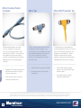
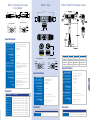
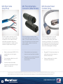
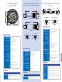
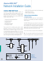
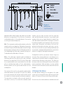
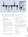
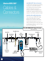
Maretron NMEA 2000 ®
About NMEA 2000 ® Cables and Connectors
Cables &
Connectors
The NMEA 2000® standard goes beyond defining
message content and includes requirements
for the cabling used to interconnect electronic
components (referred to as the physical
interface). The following catalog pages contain
the NMEA 2000® approved network interconnect
components used to build an operational network.
About Micro, Mid and Mini Cable Systems
There are three types of NMEA 2000® cabling
systems, Micro, Mid and Mini. The Micro/
Mid cable system is generally used for smaller
networks requiring less power (i.e., less than 4
amps per network leg) while the Mini cable system
is used for larger networks (i.e., more than 4 amps
but less than 8 amps per leg).
Micro/Mid NMEA 2000® Network Example
(Up to 4 amps per leg)
Micro/Mid Tee
Micro/Mid Powertap
Tee
Field-Attachable
Connectors
4�
amps
Micro
Termination
Resistor
Micro Double-ended
Cordsets
4�
amps
Micro
Termination
Resistor
Micro Bulk Cable
To Power
Source
Micro Drop-line
to NMEA 2000®
Component
50
Micro/Mid Tee
Micro �
Double-ended
Cordsets
N2KMeter
NMEA 2000®
Diagnostic Tool
Micro
Bulkhead
Feed-Thru
Multi-Port Box
Micro Drop-line
to NMEA 2000®
Component
Mini NMEA 2000® Network Example
(Up to 8 amps per leg)
Mini Powertap Tee
Mini Tee
Mini/Micro
Tee
Field-Attachable
Connectors
Mini Double-ended
Cordsets
BUS
Mini Double-ended
Cordsets
Mini
Termination
Resistor
BUS
Optional Shield
Ground Inside
V+
V+
V-
V-
SUPPLY
Mini
Termination
Resistor
Mini Bulk Cable
8 amps
8 amps
Mini
Bulkhead
Feed Thru
To Power
Source
Mini Drop-line
to NMEA 2000®
Component
N2KMeter
NMEA 2000®
Diagnostic Tool
Multi-Port Box
Micro Drop-line
to NMEA 2000®
Component
Maretron NMEA 2000 ® Cable Features
•
•
•
•
•
•
Simple trunk and drop line topology interconnects all NMEA 2000® equipment
Drop line topology allows powered component removal or re-connection while
rest of network remains operational
Cable includes power and ground for powering equipment drawing less than
1 amp/device
Connectors include keys and keyways for simple error free connections
Screw thread connectors reduce chances of accidental disconnects of
essential equipment
Waterproof connection system prevents corroded intermittent connections and
continues to operate even while submerged in the bilge
• Three independent cable shields (power pair, signal pair, and overall cable) protects
system from external noise sources such as high power radio transmitters and radar units
• Nickel plated brass connector ends ideally suited to harsh marine environment
• Phosphor bronze contact base material with gold over nickel plate for reliable connections
• Overmolded cable connector ends provide strain relief
• Simple easy to use diagnostic components enable trained and untrained personnel to
diagnose and troubleshoot network installations
51
Micro/Mid FieldAttachable Connectors
(Straight – Male/Female)
Micro/Mid FieldAttachable Connectors
(90° Male/Female)
Micro bulk cable is primarily used as
drop cable, but it can also be used at
the trunk line depending on network
power requirements. Bulk cable with
field-attachable connectors allows for
maximum flexibility as cables can be
made on the job to exact lengths.
Field-attachable connectors allow you
to make field connections to bulk cable
(see diagram). The color-coded screw
terminals match the individual wire
colors found within the bulk cable for
error-free field installation.
Like the straight Micro/Mid Fieldattachable Connectors, the 90° field
attachable connectors allow you to
make field connections to bulk cable.
The 90° connectors are particularly well
suited for tight spaces like the back of
displays where there is limited space for
a straight connector.
•
•
Color-coded screw terminals make
for error-free field installation
•
Rugged housing material designed
to withstand harsh marine
environments
Micro Bulk Cable
MICRO
•
•
Meets and exceeds NMEA 2000®
specifications for the highest
reliability
Trunk or drop cable for use with
Micro connectors
•
Useful in tight spaces or where
sharp corners need to be made
•
Waterproof rated to IP67
Used with field-attachable
connectors to build exact length
cables at the job site
Copyright 2009 Maretron, LLP. All rights reserved. As Maretron is constantly improving its products, all specifications are subject to change without notice. Maretron’s products are designed to be
accurate and reliable; however, they should be used only as aids to navigation and vessel monitoring, and not as a replacement for traditional navigation and vessel monitoring techniques. A prudent
captain or navigator never relies on a single source for navigation or system monitoring information. “NMEA 2000” is a registered trademark of the National Marine Electronics Association.
52
www.maretron.com
Micro Bulk Cable
Micro/Mid Field-Attachable
Connectors (Straight)
Micro/Mid Field-Attachable
Connectors (90°)
MALE
40 mm
1.57”
60 mm
2.36”
BLACK
RED
6-8mm
.27”
CABLE DIA.
6-8mm
.27”
CABLE DIA.
M12x1
44.5mm
1.75”
WHITE
.190±.015"
Ø20.0
Ø20.0
BLUE
M12x1
FEMALE END VIEW
MALE END VIEW
4. White
(Net-H)
1. Bare
(Shield)
2. Red
(Net-S)
3. Black
(Net-C)
3. Black
(Net-C)
5. Blue
(Net-L)
5. Blue
(Net-L)
4. White
(Net-H)
1. Bare
(Shield)
Ø20.0
MALE
2. Red
(Net-S)
M12x1
39.4mm
1.55”
6-8mm
.27”
CABLE DIA.
55 mm
2.17”
FEMALE
6-8mm
.27”
CABLE DIA.
M12x1
MALE END VIEW
FEMALE
Ø20.0
4. White
(Net-H)
Specifications
OVERALl
Outer Jacket Mat/Color:
Insulation Material:
Construction: Shielding (3 Levels):
Power Pair
Wire: Resistance/Conductor: Max Amperage: Color Code: Data Pair
Wire: Characteristic Impedance:
Capacitance: Color Code: 1. Bare
(Shield)
2. Red
(Net-S)
WIRE SIDE VIEW
OF CONTACT HOLDER
TO SHOW LABEL DETAILS
PVC/Gray
PE (data wires), SRPVC (power wires)
4x22 AWG, 22 AWG Drain
FOIL (overall), FOIL (power pair),
FOIL (data pair)
Specifications
2X22 AWG
18.1 Ohms/1000ft
6 Amps
Red/Black
2X22 (AWG)
120 Ohms ± 10%
11.33pF/fT ± 10%
White/Blue
PART NUMBER
CG1
CG1-100
3. Black
(Net-C)
3. Black
(Net-C)
5. Blue
(Net-L)
5. Blue
(Net-L)
Mechanical
Housing Mat/Plating: Contact Mat/Plating: Coupling Nut Mat/Plating:
Maximum Wire Size:
Cable Grip Range:
Electrical
Rated Current: Rated Voltage: Protection Class: Temperature Range:
Approvals
NMEA: IEC: 4. White
(Net-H)
1. Bare
(Shield)
2. Red
(Net-S)
LABEL DETAIL
WHITE
BLACK
Specifications
Nylon/Black
Brass/Gold – FA-CF-ST
Brass/Optaloy – FA-CM-ST
Brass/Nickel
18 AWG
6-8 mm
BLUE
Mechanical
Housing Mat/Plating:
Nylon/Black RED
GRAY
HOLDER
(SCALE 2:1)Contact Mat/Plating: (CONTACT
Brass/Optaloy
REMOVED)
Coupling Nut Mat/Plating:
Brass/Nickel
Maximum Wire Size:
18 AWG
Cable Grip Range:
6-8 mm
Electrical
4.0 Amps
30 V AC/ 36 V DC
Environmental
IEC IP67
-40°c TO 85°C (-40°F to 185°F)
Approvals
NMEA 2000® Approved
IEC-61162-3
Environmental
PLTC 75°C Sunlight Resistant E90625,
AWM 80°C 300V
CMX-OUTDOOR-CMG LL54185 75°C,
AWM I/II A/B 80C 300V FT4
NMEA 2000® Approved
IEC-61162-3
Products
FEMALE END VIEW
DETAIL "A"
Approvals
UL:
CSA: NMEA: IEC: 40 mm
1.57”
Products
Rated Current: Rated Voltage: Protection Class: Temperature Range:
NMEA: IEC: IEC IP67
-40°c TO 85°C (-40°F to 185°F)
NMEA 2000® Approved
IEC-61162-3
Products
DESCRIPTION
PART NUMBER DESCRIPTION
PART NUMBER DESCRIPTION
Micro Bulk Cable (Per Meter)
Micro Bulk Cable (Per 100 Meter Spool-Gray)
FA-CF-ST
FA-CM-ST
FA-CF-90
FA-CM-90
Micro/Mid Field Attachable Connector (Straight Female)
Micro/Mid Field Attachable Connector (Straight Male)
4.0 Amps
30 V AC/ 36 V DC
Micro/Mid Field Attachable Connector (90° Female)
Micro/Mid Field Attachable Connector (90° Male)
MICRO
.285±.010"
Micro Double-Ended
Cordsets
Double-ended cordsets are used
for trunk or drop lines and make
for a secure connection and simple
timesaving installation. The connectors
are keyed for error-free connection
and they are waterproof for continued
operation even while submerged in
the bilge.
MICRO
•
Rugged, IP68 rated connectors for
continued connection integrity in
marine environments
•
Various cable lengths to match
installation requirements
Micro Tee
Micro/Mid Powertap Tee
A Tee is used to tap into the trunk line
for adding a drop connection. The
standard tee is also available with a cap
for a protected diagnostic connection.
Tees can be mated with all other
devices on the network of the same
connector style.
A Powertap Tee is connected to a
network backbone just like any Tee but
rather than connecting a device their
purpose is to provide “bus” power.
Maretron Powertap Tee uniquely
provides two power inputs permitting
doubled power provision for devices.
•
Gold contacts for greatest reliability
•
•
Keyed connectors for error-free
connections
Yellow cable indicates power
and can’t be confused with gray
network cable
•
Two cable lengths to match
installation requirements
Copyright 2009 Maretron, LLP. All rights reserved. As Maretron is constantly improving its products, all specifications are subject to change without notice. Maretron’s products are designed to be
accurate and reliable; however, they should be used only as aids to navigation and vessel monitoring, and not as a replacement for traditional navigation and vessel monitoring techniques. A prudent
captain or navigator never relies on a single source for navigation or system monitoring information. “NMEA 2000” is a registered trademark of the National Marine Electronics Association.
54
www.maretron.com
Micro Double-Ended
Cordsets
55.2 [2.17]
Micro Tee
48.5 [1.91]
Ø15.0 [0.59]
48.5 [1.91]
55.2 [2.17]
12x1
M12x1
55.0 [2.17]
M12x1
Ø15.0 [0.59]
Ø15.0 [0.59]
Micro/Mid Powertap Tees
M12x1
ANTI-VIBRATION DETENT
ANTI-VIBRATION DETENT
MALE END VIEW
MALE END VIEW
4. White
(Net-H)
1. Bare
(Shield)
4. White
(Net-H)
2. Red
(Net-S)
3. Black
(Net-C)
5. Blue
(Net-L)
5. Blue
(Net-L)
5. Blue
(Net-L)
2. Red
(Net-S)
ANTI-VIBRATION DETENT
ANTI-VIBRATION DETENT
M12x1
M12x1
FEMALE END VIEW
3. Black
(Net-C)
3. Black
(Net-C)
1. Bare
(Shield)
Ø7.2 [0.28]
Ø7.2 [0.28]
FEMALE END VIEW
4. White
(Net-H)
1. Bare
(Shield)
2. Red
3. Black (Net-S)
(Net-C)
5. Blue
(Net-L)
4. White
(Net-H)
1. Bare
(Shield)
M12x1
2. Red
(Net-S)
Specifications
ELECTRICAL
CABLE
Current Rating: Voltage Rating: Outer Jacket Mat/Color: Conductor Insulation Material: Number of Conductors:
Shielding (3-Levels):
Thermoplastic PUR/Blue-Gray
Thermoplastic PUR/Blue-Gray
Brass/Gold
Brass/Nickel
0.59”
4.0 Amps
250 V
Protection Class:
Temperature Rating:
Approvals
(Cable) UL:
(Cable) CSA: NMEA: IEC:
4. White
(Net-H)
1. Bare
(Shield)
Red
IEC IP68, NEMA2.1,3,4,6P
(Net-S)
-40°C to 80°C to (-40°F to 176°F)
PART NUMBER
CM-CG1-CF-00.5
CM-CG1-CF-01.0
CM-CG1-CF-02.0
CM-CG1-CF-03.0
CM-CG1-CF-04.0
CM-CG1-CF-05.0
CM-CG1-CF-06.0
CM-CG1-CF-07.0
CM-CG1-CF-08.0
CM-CG1-CF-09.0
CM-CG1-CF-10.0
3. Black
(Net-C)
5. Blue
4. White
(Net-L)
(Net-H)
5. Blue
(Net-L)
2. Red
(Net-S)
3. Black
(Net-C)
(Net-C)
5. Blue
(Net-L)
1. Bare
(Shield)
5. Blue
(Net-L)
4. White
(Net-H)
1. Bare
(Shield)
Thermoplastic PUR/Blue
PA 6 (Nylon)/Black
Brass/Gold
Brass/Nickel
ELECTRICAL
Rated Current: Rated Voltage: 4.0 Amps
60 V
ENVIRONMENTAL
DESCRIPTION
Protection Class:
Operating Temperature:
Approvals
NMEA: IEC:
IEC IP67, NEMA 1,3,4,6
-40°C TO 80°C (-40°F to 176°F)
NMEA 2000® Approved
IEC 61162-3
PART NUMBER
CM-CF-CF
Usage
Connector
NET-C
Ground
J1
Brown
NET-S
Power
J1
Gray
SHIELD
Drain
J1 & J2
Black
NET-C
Ground
J2
White
NET-S
Power
J2
Electrical
Environmental
Approvals
Voltage Rating: Max Amperage: Protection Class: Operating Temperature: NMEA: IEC:
Thermoplastic PUR/Yellow
Thermoplastic PUR/Black
Brass/Gold
Brass/Nickel
PVC/ Yellow
PVC
5x22 AWG
250 V
4.0 Amps
IEC IP67, NEMA 1,3,4,6P
-40°C to 105°C (-40°F to 221°F)
NMEA 2000® Approved
IEC 61162-3
Products
Products
Name
Blue
Mechanical
Molded Body Mat/Color:
Contact Carrier Mat/Color:
Contact Mat/Plating: Coupling Nut Mat/Plating:
Cable Jacket Mat/Color:
Conductor Insulation Mat:
Number of Conductors:
2. Red
(Net-S)
Mechanical
Molded Body Mat/Color:
Contact Carrier Mat/Color:
Contact Mat/Plating: Coupling Nut Mat/Plating:
Color
Specifications
2. Red
(Net-S)
Specifications
PLTC 75°C Sunlight Resistant E90625, AWM 80°C 300V
CMX-OUTDOOR-CMG LL54185 75°C, AWM I/II A/B 80C 300V FT4
NMEA 2000® Approved
IEC 61162-3
Micro Double-Ended Cordset - M to F - 0.5M (gray)
Micro Double-Ended Cordset - M to F - 1M (gray)
Micro Double-Ended Cordset - M to F - 2M (gray)
Micro Double-Ended Cordset - M to F - 3M (gray)
Micro Double-Ended Cordset - M to F - 4M (gray)
Micro Double-Ended Cordset - M to F - 5M (gray)
Micro Double-Ended Cordset - M to F - 6M (gray)
Micro Double-Ended Cordset - M to F - 7M (gray)
Micro Double-Ended Cordset - M to F - 8M (gray)
Micro Double-Ended Cordset - M to F - 9M (gray)
Micro Double-Ended Cordset - M to F - 10M (gray)
3. Black
1. Bare
FEMALE
END VIEW (Net-C)
(Shield)
Products
FEMALE END VIEW
MALE END VIEW
PVC/Gray
HDPE (data pair), SRPVC
MALE(power
END pair)
VIEW
4X22 AWG, 22 AWG Drain Wire
4.
White
FOIL (Overall),(Net-H)
FOIL (Power Pair),
3. Black
FOIL (Data Pair)
ENVIRONMENTAL
23.5 [0.92]
PART NUMBER
DESCRIPTION
Micro Tee
CF-SPWR05-CF
DESCRIPTION
Micro/Mid Powertap Tee - FM (left)/
5 Meter 4 Wire Power drop (bottom)/FM (right)
MICRO
Mechanical
Contact Carrier Mat/Color: Molded Body Mat/Color:
Contact Mat/Plating:
Coupling Nut Mat/Plating:
Connector Outside Diameter:
Micro Termination
Resistors
Two termination resistors are required
on every NMEA 2000 network, one on
each end of the trunk line. Normally,
a male termination is used since male
pins tend to point back to the power
source. In cases where the gender is
reversed, a female terminator may be
required. The inline terminator is used
where the network is terminated at a
product, for example a GPS or weather
station at the top of a mast.
Micro Bulkhead
Feed-Thru
The Bulkhead Feed-Thru allows ease of
installation through panels or bulkheads
and establishes future connection points
in a network installation. The bulkhead
feed-thru also maintains the integrity
of watertight bulkheads by providing a
waterproof seal and connection.
•
MICRO
•
•
Screw terminal connector for
positive connections
•
Termination resistors are used
to terminate both ends of the
trunk line
Features rugged keyways for
positive alignment of connections
Multiport Box
(Micro-Mid Male Homerun
/ Micro-Mid Female Drops)
Multiport boxes allow several drop
cables to be consolidated and
connected back to the trunk, which
eliminates the need to have numerous
tees connected near a single point.
Multiport boxes connect back to the
trunk through a double-ended cordset
and Tee.
•
Ideal for consolidating many
connections; for example behind
dashboards
•
Requires the purchase of an
additional double-ended cordset
for connection back to the trunk
Waterproof rated to IP67
Copyright 2009 Maretron, LLP. All rights reserved. As Maretron is constantly improving its products, all specifications are subject to change without notice. Maretron’s products are designed to be
accurate and reliable; however, they should be used only as aids to navigation and vessel monitoring, and not as a replacement for traditional navigation and vessel monitoring techniques. A prudent
captain or navigator never relies on a single source for navigation or system monitoring information. “NMEA 2000” is a registered trademark of the National Marine Electronics Association.
56
www.maretron.com
Micro Termination
Resistors
Micro Bulkhead
Feed-Thru
55.2 [2.17]
Multiport Box
(Micro-Mid Male Homerun /
Micro-Mid Female Drops)
47.7 [1.88]
Ø15.0 [0.59]
(119.0)
3.5 TYP
17.0
29.4 [1.16]
21.3
TYPICAL
21.1
3.5 TYP
GASKET
M12x1
(23.0)
30.0
MOUNTING HOLE
M3 SOCKET HEAD
12mm MINIMUM
LENGTH
MALE
Ø16.2 [0.64]
48.5 [1.91]
Ø3.5 THRU
(9x) REMOVABLE LABELS
(INCLUDED)
Ø15.0 [0.59]
M12x1
M12x1
126.0
M12x1
M12x1
P1
M12x1
(16.0)
LOCKWASHER LW-M12
J3
J4
1
2
3
4
4.5
Ø12.7 [0.50]
4. White
(Net-H)
1. Bare
(Shield)
17.5 [0.69]
Ø19.6 [0.77]
FEMALE END VIEW
MALE END VIEW
Ø19.4 [0.76]
2. Red
(Net-S)
17.0 [0.67]
INLINE
J2
(25.0)
LOCKNUT LN-M12
FEMALE
J1
3. Black
(Net-C)
3. Black
(Net-C)
5. Blue
(Net-L)
5. Blue
(Net-L)
4. White
(Net-H)
P1
1. Bare
(Shield)
2. Red
(Net-S)
TYPICAL PANEL CUTOUT
WIRING DIAGRAM
FEMALE END VIEW
4. White
(Net-H)
3. Black
(Net-C)
1. Bare
(Shield)
3. Black
(Net-C)
5. Blue
(Net-L)
2. Red
(Net-S)
5. Blue
(Net-L)
J1
4. White
(Net-H)
FEMALE END VIEW
MALE END VIEW
1. Bare
(Shield)
J3
1 2 3 4 5
1 2 3 4 5
1 2 3 4 5
1 2 3 4 5
1
2
3
4. White
(Net-H)
1. Bare
(Shield)
2. Red
(Net-S)
3. Black
(Net-C)
3. Black
(Net-C)
5. Blue
(Net-L)
5. Blue
(Net-L)
4. White
(Net-H)
4
5
1. Bare
(Shield)
J2
2. Red
(Net-S)
Specifications
Specifications
Mechanical
Molded Body Mat/Color: Contact Carrier Mat/Color:
Contact Mat/Plating: Coupling Nut Mat/Plating:
Thermoplastic PUR/Blue-Gray – TR-CM, TR-CF
Thermoplastic PUR/Black – IT-CM-CF
Thermoplastic PUR/Blue-Gray – TR-CM, TR-CF
Thermoplastic PUR/Black – IT-CM-CF
Brass/Gold
Brass/Nickel
Mechanical
Contact Carrier Mat/Color:
Contact Mat/Plating: Housing Mat/Plating: Gasket Material: Accommodates Wall (thick):
Electrical
Rated Voltage: Internal Resistor:
10-30 V DC
120 Ohms (1/2 W) – TR-CM, TR-CF
121 Ohms (1/4 W) – IT-CM-CF
Environmental
Approvals
Protection Class: NMEA: IEC:
IEC IP68, NEMA 1,3,4,6P
NMEA 2000® APPROVED
IEC 61162-3
Products
PART NUMBER
TR-CM
TR-CF
IT-CM-CF
PA 6 (Nylon)/Blue-Gray
Brass/Gold
Brass/Nickel
Nitrile (Buna N)
.40” (1.0 mm) to .875” (22.2 mm)
Mechanical
Housing Mat/Color:
Receptacle Mat/Plating:
Contact Carrier Mat/Color: Contact Mat/Plating:
Environmental
Approvals
Protection Class: Temperature Range: NMEA: IEC:
250 V
4.0 Amps
5x22 AWG
PART NUMBER
BHF-CM-CF
ELECTRICAL
Operating Voltage:
Operating Current:
Nylon/Blue-Gray
Brass/Nickel
Nylon/Black
Brass/Gold
250 V 4.0 Amps
250 V
ENVIRONMENTAL
IEC IP67, NEMA 1,3,4,6
-40°C to 105°C (-40°F to 221°F)
Protection Class:
Operating Temperature:
Approvals
NMEA 2000® APPROVED
IEC 61162-3
NMEA: IEC:
IP67 – when receptacles are covered
-30°C to 80°C (-22°F to 176°F)
NMEA 2000® Approved
IEC 61162-3
Products
Products
DESCRIPTION
Micro Termination Resistor (Male)
Micro Termination Resistor (Female)
Micro Inline Terminator
Specifications
Electrical
Voltage Rating: Max Amperage: Number of Conductors:
J4
2. Red
(Net-S)
DESCRIPTION
Micro Bulkhead Feed-Thru
PART NUMBER
CM-CF-4
DESCRIPTION
Multiport Box (Micro-Mid Male Homerun /
Micro-Mid Female Drops)
MICRO
MALE END VIEW
Mid Bulk Cable
(Gray/Blue)
MID
Mid Double-Ended
Cordsets (Gray)
Mid Double-Ended
Cordsets (Blue)
Mid bulk cable is primarily used as
drop cable, but it can also be used at
the trunk line depending on network
power requirements. Bulk cable with
field-attachable connectors allows for
maximum flexibility as cables can be
made on the job to exact lengths.
Double-ended cordsets are used
for trunk or drop lines and make
for a secure connection and simple
timesaving installation. The connectors
are keyed for error-free connection and
are waterproof for continued operation
even while submerged in the bilge.
Double-ended cordsets are used
for trunk or drop lines and make
for a secure connection and simple
timesaving installation. The connectors
are keyed for error-free connection and
are waterproof for continued operation
even while submerged in the bilge.
•
Meets and exceeds NMEA 2000®
specifications for the highest reliability
•
•
•
Used with field-attachable
connectors to build exact length
cables at the job site
Rugged, IP68 rated connectors for
continued connection integrity in
marine environments
Rugged, IP68 rated connectors for
continued connection integrity in
marine environments
•
Various cable lengths to match
installation requirements
•
Various cable lengths to match
installation requirements
•
Optimized for voltage drop
sensitive networks (long runs)
because power pair wires have half
the resistance of Micro cable
•
Optimized for voltage drop
sensitive networks (long runs)
because power pair wires have half
the resistance of Micro cable
•
Optimized for voltage drop
sensitive networks (long runs)
because power pair wires have half
the resistance of Micro cable
Copyright 2009 Maretron, LLP. All rights reserved. As Maretron is constantly improving its products, all specifications are subject to change without notice. Maretron’s products are designed to be
accurate and reliable; however, they should be used only as aids to navigation and vessel monitoring, and not as a replacement for traditional navigation and vessel monitoring techniques. A prudent
captain or navigator never relies on a single source for navigation or system monitoring information. “NMEA 2000” is a registered trademark of the National Marine Electronics Association.
58
www.maretron.com
Mid Bulk Cable
(Gray/Blue)
Mid Double-Ended
Cordsets (Gray)
Mid Double-Ended
Cordsets (Blue)
48.5 [1.91]
55.2 [2.17]
48.5 [1.91]
55.2 [2.17]
Ø8.4 [0.33]
Ø8.4 [0.33]
Ø15.0 [0.59]
M12x1
M12x1
Ø15.0 [0.59]
M12x1
M12x1
WHITE
Ø15.0 [0.59]
Ø15.0 [0.59]
BLUE
FEMALE END VIEW
MALE END VIEW
.235±.010"
4. White
(Net-H)
1. Bare
(Shield)
RED
2. Red
(Net-S)
3. Black
(Net-C)
3. Black
(Net-C)
5. Blue
(Net-L)
5. Blue
(Net-L)
4. White
(Net-H)
1. Bare
(Shield)
1. Bare
(Shield)
2. Red
(Net-S)
2. Red
(Net-S)
Specifications
Mechanical
Contact Carrier Mat/Color:
Molded Body Mat/Color:
Contact Mat/Plating: Coupling Nut Mat/Plating:
Connector Outside Diameter:
.330±.005"
Specifications
Overall
Outer Jacket Mat/Color:
Insulation Material:
Construction: Shielding (3 levels):
Power Pair
Wire: Resistance/Conductor:
Max Amperage: Color Code: PVC/Gray – DG1
PVC/Blue – DB1
PE (data wires), PVC (power wires)
2x16 AWG, 2x20 AWG, 20 AWG Drain Wire
Foil (overall), Foil (power pair),
Foil (data pair)
2x20 (AWG)
120 Ohms ± 10%
10.75 pF/ft
White/Blue
Approvals
UL:
CSA: NMEA: IEC:
PLTC 75°C Sunlight Resistant E90625,
AWM 80°C 300V
CMX-OUTDOOR-CMG LL54185 75°C, AWM I/II A/B 80C 300V FT4
NMEA 2000® Approved
IEC-61162-3
Products
PART NUMBER
DG1
DG1-100
DB1
DB1-100
2x16 AWG
4.1 Ohms/1000 ft max
14 Amps
Red/Black
Data Pair
Wire: Characteristic Impedance:
Capacitance:
Color Code: Cable
Outer Jacket Mat/Color: Conductor
Insulation Material: Number of Conductors:
Shielding (3 Levels):
DESCRIPTION
Mid Bulk Cable (Per Meter-Gray)
Mid Bulk Cable (Per 100 Meter Spool-Gray)
Mid Bulk Cable (Per Meter-Blue)
Mid Bulk Cable (Per 100 Meter Spool-Blue)
Approvals
(Cable) UL: (Cable) CSA: NMEA:
IEC:
PART NUMBER
DM-DG1-DF-00.5
DM-DG1-DF-01.0
DM-DG1-DF-02.0
DM-DG1-DF-03.0
DM-DG1-DF-04.0
DM-DG1-DF-05.0
DM-DG1-DF-06.0
DM-DG1-DF-07.0
DM-DG1-DF-08.0
DM-DG1-DF-09.0
DM-DG1-DF-10.0
5. Blue
(Net-L)
5. Blue
(Net-L)
Mechanical
Contact Carrier Mat/Color:
Molded Body Mat/Color:
Contact Mat/Plating: Coupling Nut Mat/Plating:
Connector Outside Diameter:
4.0 Amps
250 V
PVC/Gray
Cable
Outer Jacket Mat/Color: Conductor
Insulation Material: Number of Conductors:
Shielding (3 Levels):
PE (data pair), PVC (power pair)
2x16 AWG, Data 2x20 AWG,
20 AWG Drain Wire
Alum/Polyester Foil (Overall),
Foil (Power Pair), Foil (Data Pair)
4. White
(Net-H)
1. Bare
(Shield)
2. Red
(Net-S)
Thermoplastic PUR/Blue-Gray
Thermoplastic PUR/Blue-Gray
Brass/Gold
Brass/Nickel
0.59”
Electrical
Current Rating: Voltage Rating: 4.0 Amps
250 V
PVC/Blue
PE (data pair), PVC (power pair)
2x16 AWG, 2x20 AWG, 20 AWG Drain Wire
Foil (Overall), Foil (Power Pair),
Foil (Data Pair)
Environmental
IEC IP68, NEMA 1,3,4,6P
-40°C to 80°C to (-40°F to 176°F)
PLTC 75°C Sunlight Resistant E90625, AWM 80°C 300V
CMX-OUTDOOR-CMG LL54185 75°C,
AWM I/II A/B 80C 300V FT4
NMEA 2000® Approved
IEC 61162-3
Approvals
(Cable) UL: (Cable) CSA: NMEA:
IEC:
Products
3. Black
(Net-C)
Thermoplastic PUR/Blue-Gray
Thermoplastic PUR/Blue-Gray
Brass/Gold
Brass/Nickel
0.59”
Environmental
Protection Class:
Temperature Rating:
3. Black
(Net-C)
Specifications
Electrical
Current Rating: Voltage Rating: FEMALE END VIEW
MALE END VIEW
4. White
(Net-H)
Protection Class:
Temperature Rating:
IEC IP68, NEMA 1,3,4,6P
-40°C to 80°C to (-40°F to 176°F)
PLTC 75°C Sunlight Resistant E90625,
AWM 80°C 300V
CMX-OUTDOOR-CMG LL54185 75°C,
AWM I/II A/B 80C 300V FT4
NMEA 2000® Approved
IEC 61162-3
Products
DESCRIPTION
PART NUMBER
Mid Double-Ended Cordset - M to F - 0.5M (gray)
Mid Double-Ended Cordset - M to F - 1M (gray)
Mid Double-Ended Cordset - M to F - 2M (gray)
Mid Double-Ended Cordset - M to F - 3M (gray)
Mid Double-Ended Cordset - M to F - 4M (gray)
Mid Double-Ended Cordset - M to F - 5M (gray)
Mid Double-Ended Cordset - M to F - 6M (gray)
Mid Double-Ended Cordset - M to F - 7M (gray)
Mid Double-Ended Cordset - M to F - 8M (gray)
Mid Double-Ended Cordset - M to F - 9M (gray)
Mid Double-Ended Cordset - M to F - 10M (gray)
DM-DB1-DF-00.5
DM-DB1-DF-01.0
DM-DB1-DF-02.0
DM-DB1-DF-03.0
DM-DB1-DF-04.0
DM-DB1-DF-05.0
DM-DB1-DF-06.0
DM-DB1-DF-07.0
DM-DB1-DF-08.0
DM-DB1-DF-09.0
DM-DB1-DF-10.0
DESCRIPTION
Mid Double-Ended Cordset - M to F - 0.5M (blue)
Mid Double-Ended Cordset - M to F - 1M (blue)
Mid Double-Ended Cordset - M to F - 2M (blue)
Mid Double-Ended Cordset - M to F - 3M (blue)
Mid Double-Ended Cordset - M to F - 4M (blue)
Mid Double-Ended Cordset - M to F - 5M (blue)
Mid Double-Ended Cordset - M to F - 6M (blue)
Mid Double-Ended Cordset - M to F - 7M (blue)
Mid Double-Ended Cordset - M to F - 8M (blue)
Mid Double-Ended Cordset - M to F - 9M (blue)
Mid Double-Ended Cordset - M to F - 10M (blue)
MID
BLACK
Mini Bulk Cable
(Gray/Blue)
Mini Double-Ended
Cordset (Gray)
Mini bulk cable is primarily used as
trunk cable, but it can also be used
as drop lines. Bulk cable with fieldattachable connectors allows for
maximum flexibility as cables can be
made on the job to exact lengths.
Field-attachable connectors allow
you to make field connections to bulk
cable. The color-coded screw terminals
match the individual wire colors found
within the bulk cables for error-free
field installation.
Double-ended cordsets are used
for trunk or drop lines and make
for a secure connection and simple
timesaving installation. The connectors
are keyed for error-free connection and
are waterproof for continued operation
even while submerged in the bilge.
•
Meets and exceeds NMEA 2000®
specifications for the highest
reliability
•
Color-coded screw terminators
make for error-free field installation
•
•
•
Trunk or drop cable for use with
Mini connectors
Rugged housing material designed
to withstand harsh marine
environments
Rugged, IP68 rated connectors for
continued connection integrity in
marine environment
•
Various cable lengths to match
installation requirements
•
Used with field-attachable
connectors to build exact length
cables at the job site
MINI
Mini Field-Attachable
Connector (Male/Female)
Copyright 2009 Maretron, LLP. All rights reserved. As Maretron is constantly improving its products, all specifications are subject to change without notice. Maretron’s products are designed to be
accurate and reliable; however, they should be used only as aids to navigation and vessel monitoring, and not as a replacement for traditional navigation and vessel monitoring techniques. A prudent
captain or navigator never relies on a single source for navigation or system monitoring information. “NMEA 2000” is a registered trademark of the National Marine Electronics Association.
60
www.maretron.com
Mini Bulk Cable
(Gray/Blue)
Mini Field-Attachable
Connector (Male/Female)
Mini Double-Ended Cordset
(Gray)
68.5 [2.70]
65.0 [2.56]
Ø27.0 [1.06]
78.5 [3.09]
Ø27.0 [1.06]
7/8-16UN
7/8-16UN
WHITE
Ø11.3 [0.44]
Ø27.0 [1.06]
BLUE
10-12mm
CABLE DIAMETER
7/8-16UN
.295±.015"
BLACK
FEMALE END VIEW
MALE END VIEW
FEMALE
RED
88.0 [3.46]
Ø27.0 [1.06]
.390±.010"
Specifications
7/8-16
Mechanical
Contact Carrier Mat/Color: Molded Head Mat/Color:
Contact Mat/Plating: Coupling Nut Mat/Plating:
Connector Outside Diameter:
MALE
FEMALE END VIEW
MALE END VIEW
Specifications
Overall
Outer Jacket Mat/Color: PVC/Blue – NB1
PVC/Gray – NG1
Insulation Material:
PE (data), PVC (power)
Construction: 2x15 AWG, 2x18 AWG,
18 AWG Drain Wire
Shielding (3 Levels):
Foil (overall), Foil (power pair),
Foil (data pair)
Power Pair
Wire: Resistance/Conductor:
Max Amperage: Color Code: 2x15 AWG
3.44 Ohms/1000 ft max
16 Amps – NB1
14 Amps – NG1
Red/Black
Data Pair
Wire: Characteristic Impedance:
Capacitance: Color Code: 2x18 (AWG)
120 Ohms ± 10%
12 pF/1000 ft Max
White/Blue
Approvals
UL:
CSA: NMEA: IEC:
PLTC 75°C Sunlight Resistant E90625,
AWM 80°C 300V
CMX-OUTDOOR-CMG LL54185 75°C, AWM I/II A/B 80C 300V FT4
NMEA 2000® APPROVED
IEC-61162-3
Products
PART NUMBER
NG1
NG1-100
NB1
NB1-100
Mini Bulk Cable (Per Meter-Gray)
Mini Bulk Cable (Per 100 Meter Spool-Gray)
Mini Bulk Cable (Per Meter-Blue)
Mini Bulk Cable (Per 100 Meter Spool-Blue)
Electrical
Environmental
Approvals
Rated Current: Rated Voltage: Protection Class: Temperature Range:
NMEA: IEC:
Glass Filled Nylon/Black
Brass/Gold
Anodized Aluminum
16 AWG
Screw Terminal
PART NUMBER
FA-NF-ST
FA-NM-ST
Current Rating: Voltage Rating: 9.0 Amps
300 V
PVC/Gray
PE (data pair), PVC (power pair)
Power 2x15 AWG, 2x18 AWG,
18 AWG Drain Wire
Braid (Overall), Foil (Power Pair),
Foil (Data Pair)
Environmental
Protection Class:
Temperature Rating:
Approvals
(Cable) UL: (Cable) CSA: NMEA:
IEC:
9.0 Amps
250 Volts
IEC IP68, NEMA 1,3,4,6P
-40°C to 80°C (-40°F to 176°F)
PLTC 75°C Sunlight Resistant E90625, AWM 80°C 300V
CMX-OUTDOOR-CMG LL54185 75°C,
AWM I/II A/B 80C 300V FT4
NMEA 2000® Approved
IEC 61162-3
Products
IEC IP67
-40°c TO 85°C (-40°F to 185°F)
NMEA 2000 Approved
IEC-61162-3
®
Products
DESCRIPTION
Mechanical
Housing Mat/Color: Contact Mat/Plating: Coupling Nut Material:
Maximum Wire Size:
Termination Method:
Electrical
Cable
Outer Jacket Mat/Color: Conductor Insulation Material: Number of Conductors:
Shielding (3-Levels):
Specifications
Thermoplastic PUR/Blue-Gray
Thermoplastic PUR/Blue-Gray
Brass/Gold
Brass/Nickel
1.06”
DESCRIPTION
Mini Field Attachable Connector (Female)
Mini Field Attachable Connector (Male)
PART NUMBER
NM-NG1-NF-00.5
NM-NG1-NF-01.0
NM-NG1-NF-02.0
NM-NG1-NF-03.0
NM-NG1-NF-04.0
NM-NG1-NF-05.0
NM-NG1-NF-06.0
NM-NG1-NF-07.0
NM-NG1-NF-08.0
NM-NG1-NF-09.0
NM-NG1-NF-10.0
DESCRIPTION
Mini Double-Ended Cordset - M to F - 0.5M (gray)
Mini Double-Ended Cordset - M to F - 1M (gray)
Mini Double-Ended Cordset - M to F - 2M (gray)
Mini Double-Ended Cordset - M to F - 3M (gray)
Mini Double-Ended Cordset - M to F - 4M (gray)
Mini Double-Ended Cordset - M to F - 5M (gray)
Mini Double-Ended Cordset - M to F - 6M (gray)
Mini Double-Ended Cordset - M to F - 7M (gray)
Mini Double-Ended Cordset - M to F - 8M (gray)
Mini Double-Ended Cordset - M to F - 9M (gray)
Mini Double-Ended Cordset - M to F - 10M (gray)
MINI
10-12mm
CABLE DIAMETER
Mini Double-Ended
Cordset (Blue)
Mini Tees
Double-ended cordsets are used
for trunk or drop lines and make
for a secure connection and simple
timesaving installation. The connectors
are keyed for error-free connection and
are waterproof for continued operation
even while submerged in the bilge.
A Tee is used to tap into the trunk line
for adding a drop connection. Two Mini
Tees are available: 1) a Mini Tee with
Mini connectors for the trunk and drop
lines, and 2) a Mini/Micro Tee with Mini
connectors for the trunk lines and a
Micro connector for the drop line.
•
•
MINI
•
Rugged, IP67 rated connectors for
continued connection integrity in
marine environment
Various cable lengths to match
installation requirements
•
Gold Contacts for greatest
reliability
Mini Powertap /
Mini Power Cord
A Powertap is connected to a network
backbone just like any Tee but rather
than connecting a device, its purpose
is to provide “bus” power. Typically
a Powertap is placed as central as
possible between total devices on
backbone. Maretron Powertap uniquely
provides two power inputs permitting
doubled power provision for devices.
•
Connects power supply to NMEA
2000® Trunk Line in convenient
plug/play fashion
•
Replaceable fuses to protect bus
and connected components from
excessive current
Keyed connectors for error-free
connections
Copyright 2009 Maretron, LLP. All rights reserved. As Maretron is constantly improving its products, all specifications are subject to change without notice. Maretron’s products are designed to be
accurate and reliable; however, they should be used only as aids to navigation and vessel monitoring, and not as a replacement for traditional navigation and vessel monitoring techniques. A prudent
captain or navigator never relies on a single source for navigation or system monitoring information. “NMEA 2000” is a registered trademark of the National Marine Electronics Association.
62
www.maretron.com
Mini Double-Ended
Cordset (Blue)
68.5 [2.70]
Mini Tees
Mini Powertap /
Mini Power Cord
28.0 [1.10]
CLEARANCE FOR
#8 (M4) FASTENER
65.0 [2.56]
3.86
[98.0]
3.38
[86.0]
1.42
[36.0]
Ø26.0 [1.02]
Ø27.0 [1.06]
17.5 [0.69]
7/8-16UN
7/8-16UN
7/8-16UN
7/8-16UN
1.42
[36.0]
2.52
[64.0]
BUS
BUS
2.05
[52.0]
Ø11.3 [0.44]
SUPPLY
Ø27.0 [1.06]
NF
FEMALE END VIEW
MALE END VIEW
SHIELD
M4 OR .138-32 SOCKET
CONNECTION
HEAD SCREW 16 MM
MINIMUM (2) NOT INCLUDED
7/8-16 UN
65.0 [2.56]
Ø26.0 [1.02]
50.0 [1.97]
10.0 [0.39]
BOTTOM VIEW
28.0 [1.10]
73.0 [2.87]
7/8-16UN
17.5 [0.69]
Ø11.0 [0.43]
Ø27.0 [1.06]
Specifications
28.0 [1.10]
CLEARANCE FOR
#8 (M4) FASTENER
7/8-16
UN
Current Rating: Voltage Rating: 7/8-16
UN
Ø26.0 [1.02]
CF
M12x1
28.0 [1.10]
9.0 Amps
300 V
73.0 [2.87]
17.5 [0.69]
37.4 [1.47]
Cable
Outer Jacket Mat/Color: Conductor Insulation Material: Number of Conductors:
Shielding (3-Levels):
PVC/Blue
PE (data pair), PVC (power pair)
2x15 AWG, 2x18 AWG, 18 AWG Drain Wire
Braid (Overall), Foil (Power Pair),
Foil (Data Pair)
31.5 [1.24]
Ø26.0 [1.02]
Specifications
Environmental
Protection Class:
Temperature Rating:
Approvals
(Cable) UL: (Cable) CSA: NMEA:
IEC:
IEC IP67, NEMA 1,3,4,6P
-40°C to 80°C (-40°F to 176°F)
Mechanical
Molded Body Mat/Color: Contact Carrier Mat/Color:
Contact Mat/Plating: Coupling Nut Mat/Plating:
PLTC 75°C Sunlight Resistant E90625, AWM 80°C 300V
CMX-OUTDOOR-CMG LL54185 75°C,
AWM I/II A/B 80C 300V FT4
NMEA 2000® Approved
IEC 61162-3
Electrical
Rated Current: Rated Voltage: Environmental
Protection Class: Temperature Range:
Products
PART NUMBER
NM-NB1-NF-00.5
NM-NB1-NF-01.0
NM-NB1-NF-02.0
NM-NB1-NF-03.0
NM-NB1-NF-04.0
NM-NB1-NF-05.0
NM-NB1-NF-06.0
NM-NB1-NF-07.0
NM-NB1-NF-08.0
NM-NB1-NF-09.0
NM-NB1-NF-10.0
DESCRIPTION
Mini Double-Ended Cordset - M to F - 0.5M (blue)
Mini Double-Ended Cordset - M to F - 1M (blue)
Mini Double-Ended Cordset - M to F - 2M (blue)
Mini Double-Ended Cordset - M to F - 3M (blue)
Mini Double-Ended Cordset - M to F - 4M (blue)
Mini Double-Ended Cordset - M to F - 5M (blue)
Mini Double-Ended Cordset - M to F - 6M (blue)
Mini Double-Ended Cordset - M to F - 7M (blue)
Mini Double-Ended Cordset - M to F - 8M (blue)
Mini Double-Ended Cordset - M to F - 9M (blue)
Mini Double-Ended Cordset - M to F - 10M (blue)
Thermoplastic PUR/Blue-Gray
Thermoplastic PUR/Blue-Gray
Brass/Gold
Brass/Nickel
9.0 Amps – NM-NF-NF
4.0 Amps (Micro) 9.0 Amps (Mini) – NM-CF-NF
600 V – NM-NF-NF
250 V – NM-CF-NF
250 V – NM-CF-NF
IEC IP67, NEMA 1,3,4,6P
-40°C to 80°C (-40°F to 176°F)
Approvals
NMEA: IEC:
Connector
Ground
Power
Ground
Power
V-1 & V-2
V+1 & V+2
V-1 & V-2
V+1 & V+2
ELECTRical
Operating Voltage:
Protection Circuit:
Schottky Rectifier:
Bus Line Minimum Conductor: Supply Line Minimum Conductor: 31.5 [1.24]
Electrical
Usage
NET-C
NET-S
NET-C
NET-S
Specifications
17.5 [0.69]
Thermoplastic PUR/Blue-Gray
Thermoplastic PUR/Blue-Gray
Brass/Gold
Brass/Nickel
1.06”
Name
Black
White
Green
Red
NMEA 2000® APPROVED
IEC 61162-3
Products
Environmental
Approvals
Temperature Range:
Storage Temperature:
NF-NM4P-NF
25 V min
Slo-Blo Fuse: 8 Amps, 250 V
Metric Fuse Block: 5x20 mm
Trip Time: 4 sec Min to 100 sec max
Type: MBR 3045PT
Max: Reverse Voltage VRWM=45 V
Max: Average Fwd Cur IFRM=30 Amps
Peak Surge Cur t=8.3 sec., IFSM=200 Amps
Max Vf = 0.65 V @ 125°C and IF=20 Amps
16 AWG 8 Amps (Mini 5-Pin)
16 AWG 8 Amps (Mini 4-Pin)
-40°C to 70°C (-40°F to 158°F)
-40°C to 85°C (-40°F to 185°F)
NMEA: IEC:
NMEA 2000® APPROVED
IEC 61162-3
Mechanical
Molded Body Mat/Color: Outer Jacket Mat/Color:
Contact Carrier Mat/Color:
Contact Mat/Plating: Coupling Nut Mat/Plating:
Conductor Insulation Mat:
Thermoplastic PUR/Yellow
PVC/Yellow
Thermoplastic PUR/Yellow
Brass/Gold
Brass/Nickel
PVC
Electrical
Environmental
Approvals
Conductors: Current Rating: Voltage Rating: Protection Class: Temperature Range: NMEA: IEC:
NM4P-01, NM4P-05
4x16 AWG
9.0 Amps
600 V
IEC IP67, NEMA 1,3,4,6P
-40°C to 105°C (-40°F to 221°F)
NMEA 2000® APPROVED
IEC 61162-3
Products
PART NUMBER
DESCRIPTION
PART NUMBER
NM-NF-NF
NM-CF-NF
Mini Tee
Mini/Micro Tee
NF-NM4P-NF
NM4P-01
NM4P-05
DESCRIPTION
Mini Powertap - Female-Female with Fuses
Mini Power Cord - Female to Pigtail - 1 Meter
Mini Power Cord - Female to Pigtail - 5 Meter
MINI
Mechanical
Contact Carrier Mat/Color: Molded Body Mat/Color:
Contact Mat/Plating: Coupling Nut Mat/Plating:
Connector Outside Diameter:
Color
Mini Termination Resistor
(Male/Female)
MINI
Mini 90° Male to Female
Connector
Mini Male to
Micro Female Reducer
Termination Resistors are required on a
NMEA 2000® network and are placed
at each end of a network trunk cable.
Like the double-ended cordsets, the
termination resistors are waterproof
and continue to function even while
submerged in the bilge.
The Mini Elbow is used in spots where
it is impossible to bend a cordset
around tight corners. The elbow easily
connects to a tee or double-ended
cordsets making 90 [degree] turns
practical at the end or anywhere along
the line.
The reducer is used to change from a
Mini cable to Micro or Mid cable. For
example, one end of the network might
be terminated at the top of the mast but
it may not be desireable to run a Mini
trunk cable up the mast. In this case,
you can switch over to Micro or Mid
cable at the base of the mast using the
reducer and continue up the mast with
Micro or Mid cable.
•
•
Mounting hole for secure fastening
of cabling system
•
Waterproof seals for reliable
connections
•
Corrosion resistant Nickle plated
Brass
•
Nickel plated brass ideally suited
for harsh marine environment
•
Weatherproof to IP67
•
Reduces Mini Backbone to Micro/
Mid Cable
•
•
Diagnostic versions indicate
correct polarity at a glance to
ensure power connections have
been made properly
Screw connector for positive
connnection
Termination resistors are used
to terminate both ends of the
trunk line
Copyright 2009 Maretron, LLP. All rights reserved. As Maretron is constantly improving its products, all specifications are subject to change without notice. Maretron’s products are designed to be
accurate and reliable; however, they should be used only as aids to navigation and vessel monitoring, and not as a replacement for traditional navigation and vessel monitoring techniques. A prudent
captain or navigator never relies on a single source for navigation or system monitoring information. “NMEA 2000” is a registered trademark of the National Marine Electronics Association.
64
www.maretron.com
Mini Termination Resistor
(Male/Female)
Mini 90° Male to Female
Connector
48.5 [1.91]
Mini Male to
Micro Female Reducer
7/8-16UN
2.100 [53.3]
Ø26.0 [1.02]
CLEARANCE FOR
#8 FASTENER (M4)
MALE
27.0
[1.06]
1.472 [37.4]
P1
7/8-16UN
7/8-16UN
Ø1.024 [26.0]
36.0
[1.42]
63.4
[2.50]
7/8-16UN
46.6 [1.83]
Ø26.0 [1.02]
FEMALE
Ø1.024 [26.0]
7/8-16UN
J1
Ø1.102 [28.0]
18.1 [0.71]
M12x1
Specifications
Electrical
Rated Voltage: Internal Resistor:
Voltage Monitoring:
(Bus Power)
Environmental
Approvals
Protection Class: Temperature Rating:
NMEA: IEC:
Thermoplastic PUR/Blue-Gray –
TR-NM, TR-NF
Thermoplastic PUR/Clear –
TRL-NM, TRL-NF
Thermoplastic PUR/Blue-Gray
Brass/Gold
Brass/Nickel
PART NUMBER
TR-NM
TR-NF
TRL-NM
TRL-NF
5. Blue
(Net-L)
3. Black
(Net-C)
5. Blue
(Net-L)
38.2 [1.50]
2. Red
(Net-S)
Specifications
300 V DC
120 Ohms (1/2 W)
Green: Correct Polarity
Red: Reversed Polarity –
TRL-NM, TRL-NF
Mechanical
Molded Body Mat/Color:
Contact Carrier Mat/Color: Contact Mat/Plating: Coupling Nut Mat/Plating:
Electrical
IEC IP67, NEMA 1,3,4,6, 13
-40°C to 80°C (-40°F to 176°F)
Environmental
NMEA 2000® Approved
IEC 61162-3
Approvals
1. Bare
(Shield)
2. Red
(Net-S)
4. White
(Net-H)
Rated Current: Rated Voltage: Protection Class: Temperature Range:
NMEA: IEC: Specifications
Thermoplastic PUR/Blue
Thermoplastic PUR/Blue
Brass/Gold
Brass/Nickel
9.0 Amps
600 V
IEC IP67, NEMA 1,3,4,6 P
-40°c TO 80°C (-40°F to 176°F)
NMEA 2000® Approved
IEC 61162-3
Mechanical
Contact Mat/Plating: Coupling Nut Mat/Plating:
Electrical
Environmental
Approvals
Rated Current: Rated Voltage: Protection Class: Temperature Range:
NMEA: IEC:
Brass/Gold
Brass/Nickel
4.0 Amps
250 V
IEC IP67, NEMA 1,3,4
-40°c TO 75°C (-40°F to 167°F)
NMEA 2000® APPROVED
IEC 61162-3
DESCRIPTION
Mini Termination Resistor (Male)
Mini Termination Resistor (Female)
Mini Termination Resistor with LED (Male)
Mini Termination Resistor with LED (Female)
4. White
(Net-H)
3. Black
(Net-C)
Products
FEMALE END VIEW
MALE END VIEW
1. Bare
(Shield)
Products
PART NUMBER
ELB-NM-NF
Products
DESCRIPTION
PART NUMBER
Mini 90° Male to Female Connector
NM-CF
DESCRIPTION
Mini Male to Micro Female Reducer
MINI
Mechanical
Molded Body Mat/Color: Contact Carrier Mat/Color:
Contact Mat/Plating: Coupling Nut Mat/Plating:
17.5 [0.69]
Mini Gender Changers
(Male/Male)(Female/Female)
Mini Bulkhead
Feed-Thru
MINI
Maretron cables have a male connector
on one end and a female connector
on the other end. Normally, the male
connector points back towards the
network power supply, but on some
occasions, this gets reversed and a
gender changer can be used to get
back to the desired connector type.
The Bulkhead Feed-Thru allows ease of
installation through panels or bulkheads
and establishes future connection
points in a network installation. The
bulkhead feed-thru also maintains
the integrity of watertight bulkheads
by providing a waterproof seal and
connection.
•
Waterproof seals for reliable
connections
•
Features rugged keyways for
positive alignment of connections
•
Easily swap connector gender to
get back to desired connector type
•
Waterproof rated to IP67
N2KMeter
The N2KMeter enables trained and
untrained personnel to diagnose and
trouble-shoot network installations
quickly and easily. Completely passive
on the network, the meter analyzes
both data and power lines on the
network. In seconds, both networkwide and device-specific traffic as well
as power monitoring information is
captured and displayed on a simple
user interface.
•
Diagnostic tool for NMEA 2000®
networks
•
Evaluates physical layer device
functions on a network
•
Data at boat can be locked in and
then evaluated later on bench
Copyright 2009 Maretron, LLP. All rights reserved. As Maretron is constantly improving its products, all specifications are subject to change without notice. Maretron’s products are designed to be
accurate and reliable; however, they should be used only as aids to navigation and vessel monitoring, and not as a replacement for traditional navigation and vessel monitoring techniques. A prudent
captain or navigator never relies on a single source for navigation or system monitoring information. “NMEA 2000” is a registered trademark of the National Marine Electronics Association.
66
www.maretron.com
Mini Gender Changers
Mini Bulkhead
Feed-Thru
N2KMeter
73.0 [2.87]
37.3 [1.47]
Electrician Mode (Simple)
49.3 [1.94]
32.7 [1.29]
7/8-16
UN
1. Plug in and set N2KMeter rotary switch to “autosearch”
2. Identify network health
• Happy face = healthy
7/8-16
UN
7/8-16UN
7/8-16UN
• Neutral face = nominal
28.0 [1.10]
• Sad face = faulty
17.5 [0.69]
LOCK
WASHER
SEE NOTE 1
19.2 [0.76]
THRUST
WASHER
Expert Mode (Advanced)
27.0 [1.06]
Ø26.0 [1.02]
Ø26.0 [1.02]
3. Scroll through faults. Refer to user manual
to link these faults to most likely network
problems or freeze and lock settings for review
back at the shop by an NMEA 2000® expert.
SEALING
GASKET
LOCKNUT
1. Scroll through NMEA 2000® parameters for each active NMEA
2000® node (mac id)
• Communication errors (rate, cumulAtive #)
• Bandwidth (% of full usage)
• Power supply and shield voltages
• Data bit quality (dominant, recessive, +, -,
differential voltage, cmv)
2. Check values (both numeric and icons)
• Happy face = within spec
Ø26.0 [1.02]
30.4 [1.20]
7/8-16UN
7/8-16UN
Ø26.0 [1.02]
37.4 [1.47]
74.5 [2.93]
• Neutral face = very close to limit
FEMALE END VIEW
MALE END VIEW
• Sad face = out of limit
17.5 [0.69]
3.Refer to user manual to link these faults to most
likely network problems
18.7 [0.74]
Mechanical
Molded Body Mat/Color: Contact Carrier Mat/Color:
Contact Mat/Plating: Coupling Nut Mat/Plating:
Mechanical
Contact Carrier Mat/Color: Housing Mat/Plating:
Contact Mat/Plating:
Gasket Material: Accommodates Wall (thick): Electrical
Rated Current: Rated Voltage: Environmental
Protection Class: Temperature Range:
Specifications
Thermoplastic PUR/Blue-Gray
Thermoplastic PUR/Blue-Gray
Brass/Gold
Brass/Nickel
9.0 Amps
600 V
IEC IP67, NEMA 1,3,4,6P – NM-NM
IEC IP67, NEMA 1,3,4,13 – NF-NF
-40°C to 70°C (-40°F to 158°F) – NM-NM
-40°C to 55°C (-40°F to 131°F) – NF-NF
Approvals
NMEA: IEC:
NMEA 2000® Approved
IEC 61162-3
Products
PART NUMBER
NM-NM
NF-NF
Thermoplastic PUR/Blue-Gray
Brass/Nickel
Brass/Gold
Nitrile (Buna N)
.040” (1.0 mm) to .875” (22.2 mm)
Electrical
Voltage Rating: Max Amperage: Number of Conductors:
Environmental
Approvals
Protection Class: Temperature Range: NMEA: IEC:
600 V
9.0 Amps
5x22 AWG
IEC IP67
-40°C to 105°C (-40°F to 221°F)
NMEA 2000® Approved
IEC 61162-3
PART NUMBER
BHF-NM-NF
Network 7 - 30v DC < 90MA
Batteries 2 X AA Alkaline Batteries
6 Hours Of Operation Approx.
1 Year Data Retention
Micro Connector
125k, 250k and 500k (Auto-detect)
Bus Power±100mv, Bus Signal±20mv
Bus Power 0 to 25v with over/under
Range Indication Bus signal -5 To 10v
with over/under range Indication
Bus Power 1 Khz Bus Signal Ideal
Sample Pt±250ns
NMEA 2000® Spec for Network Power
Detects Bus Idle In Real Time
Detects 100% of Individual Can Frames in Real Time
Detects 100% of Individual Error
Frames in Real Time
Approvals
Products
DESCRIPTION
Mini Gender Changer (Male/Male)
Mini Gender Changer (Female/Female)
Mechanical
Power Supply:
Connectors:
Band Rates:
Analog Accuracy:
Analog Range:
Analog Sample Rate:
Signal Error Threshold:
Bus Load Measurement:
Bus Message
Rate Measurement:
Error Rate Measurement: NMEA: NMEA 2000® Approved
Products
DESCRIPTION
PART NUMBER
Mini Bulkhead Feed-Thru
N2KMETER-01
DESCRIPTION
Diagnostic Meter w/1m Micro Cordset
MINI
Specifications
Specifications
Maretron NMEA 2000 ®
Network Installation Guide
Installing an NMEA 2000® Network
Installing an NMEA 2000® network consists of
inter-connecting NMEA 2000® electronic devices using
plug-and-play cables and connectors. The following pages
provide a brief description of how to setup a NMEA 2000®
network using five basic steps:
1.
2.
3.
4.
5.
Cable and Connector Network Basics
Installing Terminators
Supplying Power
Grounding the Network
Checking the Network
Please note that this installation guide contains a brief
description of the basic concepts of installing an NMEA
2000® network and Maretron suggests that you consult
a trained professional for any installation. You can learn
more about installing NMEA 2000® networks by contacting
the National Marine Electronics Association (NMEA) at
www.nmea.org and consulting the following documents:
• NMEA 2000® Standard for Serial-Data Networking of
Marine Electronic Devices
• NMEA Installation Standards
1. Cable and Connector Network Basics
1.1 Network Topology
The NMEA 2000® cable system uses a trunk (sometimes
referred to as the backbone) and drop line topology as
shown in Figure 1.
The NMEA 2000® cable system includes five wires within a
single waterproof cable: two signal wires, power and ground
wires, and a drain wire. The drain wire shields the signal, power,
and ground wires from external Radio Frequency Interference
(RFI) and helps reduce RFI emission from the cable.
You can connect devices using one of three cable options:
Mini - This is commonly used for the trunk line on the network
because of its greater current carrying capacity (8 amps) as
Multi
Port
Box
68
Figure 1
NMEA 2000®
Network Topology
Figure 2
Maximum Cable
Length Determination
opposed to Micro cable (4 amps). Mini cable has an outside
diameter in the range from 0.41 to 0.49 inches. Its maximum
installed bend radius is 7x the cable diameter. You can also
use this type of cable for drop lines.
Mid - This is commonly used for smaller networks as either the
network trunk line or as drop lines. Mid cable and connectors
are rated to 4 amps just like the Micro cable, however the larger
diameter power conductors within the Mid cable provides for
less voltage drop over Micro cable, especially for long runs.
The diameter of the Mid cable is 0.33 inches.
Micro - This cable type is typically used as the drop line
connecting devices to the main trunk line with an outside
diameter in the range from 0.24 to 0.28 inches. Micro cable
has a smaller diameter and is more flexible than mini cable
with an installation bend radius of 7x the cable diameter.
Smaller networks use this type of cable for both the trunk
and drop lines.
You construct the trunk line using double-ended cordsets
connected between tees or taps. One end of the cordset
has a male connector with male pins while the other end of
the cordset has a female connector and female receptacles.
The connectors are keyed so they can only connect to
each other in one way. As an alternative to double-ended
cordsets, you can make your own trunk line using bulk
cable and field-attachable connectors. If you decide to add
equipment later, you can simply disconnect a cordset from
a tee, add another tee directly to the existing tee, re-connect
the cordset and add the new component to the system using
a drop cable. Alternatively, you could cut the trunk line,
add two field-attachable connectors and insert a new tee.
Trunk lines can also be run up to watertight bulkheads and
connected to a waterproof bulkhead feed-thru connector to
maintain the integrity of watertight compartments.
To drop off the trunk line, you connect a device using a tee
connector. Daisy chaining of devices is not allowed, as it is
a requirement to be able to remove a component from the
network without affecting any other device. This allows you
to remove a device for servicing while the rest of the network
remains operational. Multi port boxes are also available
where instruments tend to be clustered, around the helm for
example.
1.2 Maximum Cable Distance
The cable distance between any two points in the cable
system must not exceed 200 meters (656 feet) for the Mini
cable or 100 meters (328 feet) for the Micro and Mid cable.
For most cases, the maximum distance should be measured
69
between termination resistors. However, if the distance from
a trunk line tee to the farthest device connected to the trunk
line is greater than the distance from the tee to the nearest
terminating resistor (TR), then you MUST include the drop
line length as part of the cable length in your maximum cable
distance calculation. Figure 2 shows an example where both
5 meter drops must be included in the maximum cable
distance since the drops are longer than the distance from
the tee to termination resistor.
1.5 Maximum Number of Devices
1.3 Cumulative Drop Line Length
The following table shows the color, name, and usage for
each wire contained within the cable.
The cumulative drop line length refers to the sum of all drop
lines, Mini, Mid or Micro cable in the cabling system. This
sum cannot exceed 78 meters (256 feet). Figure 3 shows
an example using four drop tees and two multiport drops to
attach 11 devices to the trunk line. The cumulative drop line
length is 37 meters (122 feet) and no single device is more
than 6 meters (20 feet) from the trunk line.
1.4 Maximum Drop Line Length
The maximum cable distance from any device on a branching
drop line to the trunk line is 6 meters (20 feet).
A maximum of 50 physical devices shall be connected to
the network, and the disconnection of any device shall not
interrupt any other device on the network.
1.6 NMEA 2000® Cable
The Mini, Mid and Micro cables contain five wires: One
twisted pair (red and black) for 12VDC power, one twisted
pair (blue and white) for signal and a drain wire (bare).
Color
Name
Usage
White
NET-H
Signal
Blue
NET-L
Signal
Bare
SHIELD
Drain
Black
NET-C
Ground
Red
NET-S
Power
Multi
Port
Box
70
Figure 3
Maximum
Cumulative
Drop Line Length
Determination
Figure 4
Figure 5
Mini Powertap
Micro/Mid Powertap
1.7 NMEA 2000® Connectors
3. Supplying Power
Connectors attach cables to devices or other components
of the NMEA 2000® cable system. This allows the network
to be completely “plug-and-play”. Connections can be
made with pre-molded cordsets or with field-attachable
connectors. The following diagram shows the pins found
within Mini connector and the Micro and Mid connector and
the corresponding wire colors for those pins.
NMEA 2000® networks can use a power supply originating
from a single-point connection to the vessel’s 12 volt battery
or one or more isolated power supplies distributed along the
network, but not a combination of battery and power supply
connections. For the purpose of this installation guide, we will
focus on the power source being a single-point connection
to the vessel’s battery. Over current protection should be
provided and should be sized in accordance with ABYC E-11,
AC and DC ELECTRICAL SYSTEMS ON BOATS, taking into
consideration the smallest gauge of cable being used for the
backbone or drop cables. The NET-S wire is connected to
the positive side of the battery while NET-C is connected to
the negative side of the battery.
2. Installing Terminators
Termination resistors are attached to each end of the trunk
cable to reduce reflections of the communication signals
on the network. If you do not use termination resistors as
described, the network will not operate properly. Termination
resistors are typically connected directly to the last tee on
the trunk line although they can be connected to a cordset
extending from the last tee on a trunk line. Inline terminators
are also available and they are used to terminate the network
at the last product.
3.1 Mini Power Connection
Power is supplied to a Mini trunk line via a Powertap that is
shown in Figure 4. Note that the Mini power cable does not
have a shield wire as this connection is made to the screw
terminal on the Powertap itself.
3.2 Mini Power Capability
Although Mini cable is rated to 8 amps, the cable system can
support a total load of more than 8 amps. For example, 16
amps of power could be supplied to the middle of the trunk
where 8 amps is supplied to both sides of the power tap. The
71
Powertap can handle large loads as long as no more than 8
amps is drawn through any single segment of the trunk line.
However, cable resistance may limit your application to less
than 8 amps.
network consists of two legs, one leg extending in each
direction from the power insertion point. Figure 7 shows a
middle-powered network.
3.3 Micro/Mid Power Connection
The NMEA 2000® network is designed to work properly as
long as there is no more than a 1.5 volt difference in the
power supply voltage between any two devices on the
network. Therefore, you should perform an estimate of the
voltage drop across a network using the following equation:
Like the Mini power connection, power is supplied to a Micro/
Mid trunk line via a Powertap, which is shown in Figure 5.
3.4 Micro/Mid Power Capability
Micro/Mid cable is rated to 4 amps but like Mini cable,
strategic placement of the power source could support higher
current. For example, 8 amps of power could be supplied to
the middle of the trunk where 4 amps is supplied to both
sides of the power tap. It can handle large loads as long as
no more than 4 amps is drawn through any single segment
of the trunk line. However, cable resistance may limit your
application to less than 4 amps
3.5 End-Powered Network
End-powered networks are typically seen on smaller vessels
with only a few NMEA 2000® devices. Figure 6 shows an
end-powered network.
3.6 Middle-Powered Network
A middle-powered network is typically found on larger
vessels and is any network where the power is connected
to the network at some location other than at the end. This
3.7 Maximum Power Supply Voltage Drop
Voltage Drop = 0.1 x Network Loads x Network Length x Cable Resistance/100
Where: Network Loads is sum of Load Equivalent Numbers (LEN)
for all devices (see device nameplate)
Network Length is in meters
Cable resistance is in ohms/100 meters
(see pages 1 and 9 specifications)
Power supply voltage drop estimates resulting in less
than 1.5 volts across the entire network require no further
analysis. Likewise, estimates ranging between 1.5 and 3.0
volts require no further analysis as long as a mid-powered
network is used. Occasionally, estimated power supply
voltage drops will occur outside these limits and will require
further consideration through detailed calculations by
certified technicians.
4. Ground the Network
The NMEA 2000® network should be grounded at ONE
Electronic Compass
Trunk Line
Depth Sounder
Compass Display
0.3 meter
2 loads
TR
10
meters
.03 meter
0.3 meter
2 loads
.03 meter
0.3 meter
2 loads
Speed Log
72
Power from
Battery
Drop Line
2 meters
1 load
Device or Node
TR
2
meters
5
meters
2 meters
1 load
Autopilot
TR
Drop Tee
Figure 6
End-Powered Network
Autopilot
Speed Log
Trunk Line
TR
5 meters
Drop Line
0.3 meters
2 loads
1 meter
1 load
20 meters
5 meters
2 meters
1 load
0.3 meters
0.3 meter
2 loads
Electronic Compass
Compass Display
Power from
Battery
location. Grounding at more than one location may
produce ground loops, which can cause problems with
communications on the network. In addition to the ground
wire, connect the drain or SHIELD wire at the supply ground
location and NO other place.
5. Checking Your Network
Verify that the network has been correctly designed and
installed by reviewing the following checklist:
• Number of devices does not exceed 50
• Maximum Mini cable distance between any two
devices does not exceed 200 meters (656 feet)
• Maximum Micro/Mid cable distance between any two
devices does not exceed 100 meters (328 feet)
• Maximum cumulative drop line length does not exceed
78 meters (256 feet)
• No drop should be greater than 6 meters (20 feet)
• Termination resistors are installed on both ends of the
trunk
• The network is grounded at a single location
• The SHIELD wire is connected to a single point, the
supply ground
If you are having difficulties with the network make sure to
check the following most common network problems:
0.3 meters
Device or Node
TR
TR
Drop Tee
0.3 meter
2 loads
Depth Repeater
Figure 7
Middle-Powered Network
• More or less than two terminating resistors
• Loose connections, make sure that all connectors are
securely fastened
• Excessive trunk line length-especially with Micro cable
• Excessive drop line cable length
• Improper shield and ground connection at the
power supply
• Shorts and opens in field-attachable connectors
• Failure to perform power distribution calculations for
new installations and when adding new devices
• Using a typical device current rather than maximum
current for power distribution calculations
In order to insure the proper installation and configuration of
an NMEA 2000® network, it is a good idea to have available at
least one N2KMeter. The N2KMeter greatly simplifies network
diagnostics and can detect many fault conditions including:
• Opens and shorts
• Incorrect topology
• Bad nodes
• Bad termination
• Improper shield connection
• Intermittent problems
• Excessive scan rate
• Common mode voltage
73
www.maretron.com
09
Maretron Corporate Office
9014 N. 23rd Avenue, Suite 10
Phoenix, AZ 85021
Toll Free: 866-550-9100
Phone: 602-861-1707
Fax: 602-861-1777
Email: [email protected]
Web: www.maretron.com