1
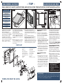
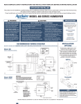
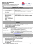
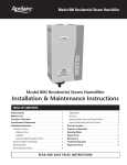
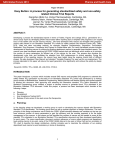
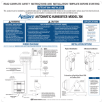
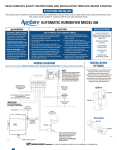
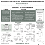
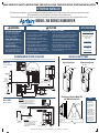
READ COMPLETE SAFETY INSTRUCTIONS AND INSTALLATION TEMPLATE BEFORE STARTING INSTALLATION
ATTENTION INSTALLER:
This product must be installed by a qualified heating and air conditioning contractor. Failure to do so could result in serious injury from electrical shock.
This product must be installed in compliance with all local, state and federal codes.
Proper humidification and humidity control also requires that the home be constructed in accordance with local codes and good building practices.
MODEL 700 SERIES HUMIDIFIER
WARNING
CAUTION
SPECIFICATIONS
RISK OF PROPERTY AND EQUIPMENT DAMAGE.
1. ELECTRICAL SHOCK HAZARD.
Disconnect electrical power to the
furnace before starting installation.
Failure to do so could result in serious
injury from electrical shock.
1. Do not install humidifier where freezing temperatures
could occur. The water line could freeze and crack
causing water damage to the home.
2. Do not install humidifier on the furnace jacket.
3. Do not install humidifier on a plenum face where the
blanked off ends of the cooling coil will restrict air
movement through the humidifier.
4. Do not set humidity level above recommended or to
recommended level if condensation exists on inside
windows of any unheated space, as condensation
damage may result. Excess humidity can cause
moisture accumulation which can allow the possibility
for mold growth in the home.
2. SHARP EDGES HAZARD. Sharp
edges may cause serious injury from cuts.
Use care when making plenum openings
and handling ductwork.
3. RISK OF SCALDING. Water
temperature over 125°F can cause severe
burns and scald instantly. Shut off the hot
water supply before disconnecting or
tapping into any hot water supply line.
HUMIDIFIER DIMENSIONS
Width 15 29⁄ 32”
Height (including solenoid valve
and drain spud) 18”
Depth 10 11⁄ 32”
5. Do not connect the Model 700 or 700M power cord to multispeed furnace blower motors or blower motors other than 120
VAC. Premature component failure may result. Use Research
Products Corporation Model 50 Current Sensing Relay.
6. When installing Humidifier Control on a downflow furnace,
ensure blower continues to run after a heat call is satisfied to
eliminate high temperatures from damaging the Control.
7. Do not install humidifier where water pressure exceeds
125 psi, since damage to the humidifier may result. Follow
codes in effect concerning pressure reduction.
8. Do not install humidifier on the supply plenum where static
pressure exceeds 0.4 in. wg.
RECOMMENDED WIRING DIAGRAMS
PLENUM OPENING
14 3⁄ 4”W x 14 5⁄ 16”H
WATER FEED RATE
6 gph
ELECTRICAL DATA
120 VAC-60 Hz, 0.8 AMP
INSTALLATION OPTIONS
(SEE STEP 6 ON BACK AND “HUMIDIFIER CONTROL SAFETY AND INSTALLATION INSTRUCTIONS” FOR DETAILED WIRING INSTRUCTIONS)
Typical Installation
Model 700
DIGITAL HUMIDIFIER
CONTROL
Alternate Installation
HOT WATER
RETURN
POWER
R
C
INPUTS
A
B
ODT
W
RETURN
SUPPLY
ADHC TERMINAL STRIP
SUPPLY
OUTPUTS
G
H
H
Gf
NORTH, EAST
OR WEST SIDE
OF HOME
OUTDOOR
TEMPERATURE
SENSOR FOR
AUTOMATIC MODE
120 VAC OUTLET
CONNECT DRAIN LINE HERE
ABOVE EXPECTED
SNOW LINE
C
C
G
G
Y
Y
THERMOSTAT
MANUAL CONTROL
90-921
BROWN WIRES
110 VAC
W
W
Model 700M
CONNECT TO HOT WATER SUPPLY
R
R
90-1514
FURNACE
CONTINUOUSLY POWERED 24 VAC
TRANSFORMER PROVIDED WITH HUMIDIFIER
Orientation of Aprilaire Model 700
and 700M to Cooling Coils
IMPORTANT
USE 120 VAC POWER SOURCE OTHER THAN FURNACE MOTOR
CIRCUIT. HOWEVER, THE TRANSFORMER CAN BE POWERED OFF
THE HOT 120 VAC LINE BEFORE IT ENTERS THE FURNACE.
BLANKED OFF
END OF COIL
• DO NOT WIRE TRANSFORMER INTO FURNACE BLOWER CIRCUIT.
24 VAC FURNACE ACCESSORY
TERMINALS OR TRANSFORMER
(10VA MINIMUM)
SHUT-OFF
(SADDLE VALVE)
COMMON
LO
COOLING COILS IN
WARM AIR PLENUM
MODEL 50
CURRENT SENSING RELAY
(IF REQUIRED)
Aprilaire to
be installed
as shown in
relation to
cooling coils.
IMPORTANT
FURNACE
BLOWER MOTOR
WHEN MODEL 50 CURRENT SENSING RELAY IS USED:
• WIRE MODEL 50 CURRENT SENSING RELAY
INTO 24 VAC HUMIDIFIER CONTROL CIRCUIT
ONLY! DO NOT INSTALL IN TRANSFORMER
PRIMARY CIRCUIT.
120 VAC
OUTLET
CONNECT DRAIN LINE HERE
90-1208
BROWN WIRES
RESEARCH PRODUCTS CORPORATION • P.O. BOX 1467 • MADISON, WI 53701-1467 • CALL 800/334-6011 • FAX 608/257-4357
1. Models 700 and 700M
are not suitable for
installation on ducts
with horizontal airflow.
Performance will be
reduced.
2. When installing the
Aprilaire humidifier with
the Aprilaire Digital
Humidifier Control or on
a heat pump system, use
hot water. The heated
water supplements the
reduced supply air
temperature as added
heat for evaporation.
WATER SUPPLY
HI
NOTES
90-922
– TOP –
READ REVERSE SIDE FIRST!
READ REVERSE SIDE FIRST!
READ COMPLETE SAFETY INSTRUCTIONS AND INSTALLATION TEMPLATE BEFORE STARTING INSTALLATION
FURNISHED ITEMS
Figure 1
Figure 2
Figure 3
Figure 4
24 VAC Transformer
Digital Humidifier Control
(Model 700 only)
Manual Humidifier Control
(Model 700M only)
Humidifier Control
Installation Instructions
Saddle Valve
Humidifier Installation Template
ITEMS NOT FURNISHED
Mounting screws
(sheet metal screws)
Water supply line (1 ⁄ 4” copper)
Drain line (1 ⁄ 2” I.D. hose)
Low voltage wire
Model 50 Current Sensing Relay
(if required)
1. Detach the cover assembly by
lifting the latch at the bottom.
Remove the Water Panel®
evaporator assembly by grasping
at top and tipping out. See Figure 1.
2. Position template on supply
plenum. Make sure template is
level. Allow clearance for drain line
and for servicing. See “Installation
Options” on opposite side for
position relative to cooling coil.
90-923
90-924
90-925
5. Insert Water Panel Evaporator
Trace template outline. Cut 14-3/4”
wide x 14-5/16” high opening. Avoid
injury from sharp edges.
assembly into base. Make sure bottom of
scale control insert (5) is over drain
opening. Snap top of evaporator assembly
into base.
3. Position base (2) in duct opening
top-first so hooks engage sheet metal
at top. See Figure 2. Insert bottom of
base and slide down to engage hooks
at bottom.
6. Control installation and wiring.
Disconnect electrical power to furnace
before wiring control. In order for
humidifier to operate, furnace must be on
and RH must be below set-point of control.
Wiring diagrams illustrate recommended
method of detecting furnace operation.
4. Rotate swing locks to secure base
to duct. See Figure 3. Fasten base to
duct using 4 sheet metal screws in
holes provided.
PARTS LIST
1. Front Cover
2. Base
3. Orifice Plate
4. Motor Mount Bridge
5. Scale Control Insert
6. Water Panel Evaporator
7. Water Distribution Tray
8. Fan Blade
9. Motor
16
15
6
3
2
Manual Control can be mounted in
return duct or on wall in living space.
Knob and cover must be removed to
mount control. See wiring diagram for
24V control connections.
• For return duct mounting, position
template in convenient location on duct.
Avoid injury from sharp edges when
cutting opening. Make sure foam
gasket is in place and secure control to
duct using 2 screws in holes provided.
• For wall-mount, select location that
will not be affected by drafts or heat
sources. Remove and discard foam
gasket and secure control over wire
access opening using screws &
anchors provided.
7
17
MANUAL HUMIDIFIER CONTROL,
MODEL 700M:
10. Motor Mount Gasket
11. Control Relay
12. Power Cord
13. Strain Relief Bushing
14. Solenoid Valve
15. Connector Plug
16. Feed Tube
17. Nozzle
18. Relay Connector Plug
DIGITAL HUMIDIFIER CONTROL,
MODEL 700:
• Select location for control on return
duct. Drill 3/4” hole for sensor. Knob
and cover must be removed to mount
control. Place control on duct with RH
sensor extending into duct opening.
Make sure gasket is in place around
sensor cage. Secure control to duct
using 2 screws in openings provided.
8
5
4
18
14
• See wiring diagrams on template and
control instructions for 24 V control
connections.
10
9
13
12
7. Humidifier will function with cold,
hot, softened or unsoftened water.
Hot water (140°F max) is strongly
recommended to provide maximum
evaporative capacity. Saddle valve
provided may be used to tap into water
supply. See installation instructions on
saddle valve package. Saddle valve is
designed to be fully opened or closed.
Do not use to regulate flow.
8. Run 1/4” copper tubing from saddle
valve to solenoid valve. DOUBLE-WRENCH
TO PREVENT LEAKING. See Figure 4.
9. INSTALL DRAIN IN ACCORDANCE
WITH LOCAL CODES. Run 1/2” I.D. hose
from drain spud to floor drain. Make
sure drain has constant downward
slope and is not kinked. Do not overtighten hose clamp onto drain spud. Do
not use solvent adhesive on drain spud.
10. Check humidifier operation. Open
saddle valve and turn control to highest
setting. Turn on furnace. Allow
humidifier to run until water flows from
drain. Make sure all electrical
connections are secure and all
plumbing connections are water-tight.
Set control to proper setting.
NOTE: BEFORE LEAVING THE
JOB SITE, MAKE SURE:
1. Saddle valve is fully open.
2. All plumbing connections are
watertight.
3. Humidifier functions properly.
11
1
TEMPLATE MUST BE LEVEL
90-926
90-1244
IMPORTANT! Be sure owner’s manual containing instructions for operation
and warranty information is given to owner in order to avoid unnecessary calls.
Warranty is void unless humidifier is installed by qualified heating and air conditioning
contractor due to possible misapplication of product.
10008976 B2205118A 4.10