1
TM
Cable Series
Engine Control Module (ECM)
Operation and Maintenance Manual
Effective: October, 2003
®
TM
2
TM
744-862-C0-003 Rev.C
TM
Overview:
The purpose of the AlphaGen ENGINE CONTROL MODULE(ECM)
Operation and Maintenance Manual is to provide a high-level
overview of the system and to detail the operation and
maintenance of the module.
Audience:
This manual intended for the operator of the system.
This Operation and Maintenance Manual is comprised of five sections:
Section 1.
Section 2.
Section 3.
Section 4.
Section 5.
744-862-C0-003 Rev.C
System Overview. This section describes the
theory of operation of the ECM.
ECM Indicators and Controls. Describes the various
module controls.
ECM Alarms and Notifications. Describes the functions
monitored and reported by the ECM.
ECM Configuration and system interface. Describes the
setup and connection of the module.
System self-test and maintenance. Describes testing of
the engine generator and module.
TM
3
Engine Control Module (ECM)
Table of Contents
Section 1, System Overview
1.1
1.2
Introduction ...............................................................................
Theory of Operation ....................................................................
1.2.1. Normal Operating Condition ..................................................
1.2.2. Standby Operating Condition (less than 3 minutes) ..................
1.2.3. Standby Operating Condition (more than 3 minutes) ................
1.2.4. Normal APU Shutdown .........................................................
1.2.5. Abnormal APU Shutdown ......................................................
1.2.6. ECM Operating Mode Summary ...............................................
13
17
17
17
17
18
18
19
Section 2, ECM Indicators and Control Functions
2.1
2.2
Indicators .................................................................................. 21
Control Functions ........................................................................ 23
Section 3, ECM Alarms and Notifications
3.1
3.2
3.3
3.4
3.5
3.6
Alarms Classifications ...................................................................
Notifications ...............................................................................
Alarm and Notification Indications ..................................................
Standard ECM-Transponder Interconnection ....................................
ECM Transponder Interface ...........................................................
Transponder System Block Diagram ................................................
25
28
29
30
32
33
Section 4, ECM Configuration/System Interface
4.1
4.2
4.3
4.4
4.5
ECM Configuration DIP Switch, Fuses .............................................
ECM Configuration .......................................................................
System Interface ........................................................................
ECM input voltage and line sense configurations ...............................
ECM System Parameters ...............................................................
4.5.1 Low DC Bus Level .................................................................
4.5.2 High DC Bus Level ................................................................
4.5.3 Service Interval ...................................................................
4.5.4 Service Countdown ..............................................................
4.5.5 Total Engine Runtime ............................................................
4.5.6 Auto-test Interval ................................................................
4.5.7 Auto-test Countdown ...........................................................
4.5.8 Auto-test Duration ...............................................................
4.5.9 Start Delay .........................................................................
4.5.10 Shutdown Delay ..................................................................
35
36
37
38
39
39
39
39
39
39
40
40
40
40
40
Section 5, System Self-test and Maintenance
5.1
5.2
4
Self-Test ................................................................................... 41
System Maintenance ................................................................... 43
TM
744-862-C0-003 Rev.C
Engine Control Module (ECM)
List of Figures
Section 1, System Overview
Fig. 1-1
Fig. 1-2
Fig. 1-3
Fig.1-4
Front view, Engine Control Module (ECM) ...................................
Run/Auto/Stop and Service/Reset switches ...............................
Location of Engine Control Module (ECM) ..................................
ECM Printed circuit boards .......................................................
14
15
15
16
Section 2, ECM Indicators and Control Functions
Fig. 2-1 Engine Control Module LED indicators and switches. ................... 22
Fig. 2-2 Run/Auto/Stop and Service/Reset switches ............................... 24
Section 3, ECM Alarms and Notifications
Fig.
Fig.
Fig.
Fig.
Fig.
3-1
3-2
3-3
3-4
3-5
Major, Minor Alarm Indications, and Notifications ........................
Transponder-to-ECM interconnect cable ....................................
ECM connector arrangement ....................................................
SCM-to-ECM interconnect cable ...............................................
ECM-to-SCM connector arrangement ........................................
29
30
30
31
31
Section 4, ECM Configuration/System Interface
Fig.
Fig.
Fig.
Fig.
Fig.
4-1
4-2
4-3
4-4
4-5
ECM Configuration DIP Switch and fuse locations ........................
SW5, ECM PCBA .....................................................................
ECM/APU Interconnection, 3.0 kW configuration .........................
ECM/APU Interconnection, 5.0 kW configuration .........................
ECM Power Board ...................................................................
34
35
36
37
38
List of Tables
Table 1-1 Normal Mode Crank Cycle ....................................................... 18
Table 3-1 ECM Transponder interface ..................................................... 32
Table 4-1 ECM switch configurations. ..................................................... 36
744-862-C0-003 Rev.C
TM
5
Engine Control Module (ECM)
IMPORTANT SAFETY INSTRUCTIONS
CONTAINED IN THIS MANUAL
CAUTION
HAZARDOUS CONDITION
To reduce the risk of electrical shock, injury or death caused by explosion of
fuel or moving parts, and to ensure the safe operation of this unit, the
following symbols have been placed throughout the manual. Where these
symbols appear, servicing must be performed only by qualified personnel.
DANGEROUS VOLTAGE
This symbol indicates a “dangerous voltage” exists in this area of the
product. Use caution whenever working in the area to prevent
electrical shock.
ATTENTION
This symbol indicates important installation, operation or maintenance
instructions. Always follow these instructions closely.
ELECTROSTATIC DISCHARGE SENSITIVITY
This symbol indicates the need for following approved procedures for
handling electrostatic-sensitive components.
INHALATION HAZARD
This symbol indicates an “inhalation hazard” exists in this area of the
product. Use caution whenever working in the area to prevent possible
inhalation of harmful (fuel or exhaust) vapors.
NO MATCHES OR OPEN FLAMES
This symbol indicate a fire or explosive hazard exists in this area of
the product. Use caution whenever working in the area to prevent the
possible combustion of fuel or vapors.
MECHANICAL OR MOVING PARTS HAZARD
These symbols indicate the presence of a “mechanical or moving parts
hazard” in this area of the product. Use caution whenever working in
the area to prevent possible injury to the operator or servicepersonnel.
LEAK HAZARD
This symbol indicates a “leak hazard” exists in this area of the product.
Use caution whenever working in the area to prevent and correct any
leaks detected.
HOT SURFACES
This symbol indicates the presence of high temperatures which result
from the operation of the system. To prevent burns, do not touch
these areas while the system is in operation or immediately after it has
been turned off.
6
TM
744-862-C0-003 Rev.C
Engine Control Module (ECM)
SAFETY PRECAUTIONS
NOTE:
Failure to follow these precautions could result in
injury or death caused by the explosion of fuel,
moving parts hazards or electrocution.
CAUTION:
This set of procedures will require the
operation of the generator and should
only be performed by qualified,
experienced personnel in a well-ventilated area.
• Technicians must have easy access to a fire extinguisher at all
times.
• Propane/Natural Gases are highly explosive. Use extreme
caution while handling and operating the Generator gas package
and equipment. Keep flame or spark away from Propane
bottles. Do not smoke during assembly of gas package.
• Any test equipment used in the testing of the CE Series system
must have isolated inputs to prevent shock hazards and short
circuits with the enclosure or other grounded objects.
• Run Generator only in properly ventilated areas. Exhaust
gasses can be lethal. Prolonged exposure can cause nausea,
headaches, dizziness, or Carbon Monoxide poisoning.
• All pipe connections must be leak tested immediately.
• Output of upper air dam must be unobstructed.
• “Test” Propane bottles MUST not come into contact with the
cabinet(s). Use a Digital Voltmeter (DVM) to ensure proper
cabinet grounding.
• “Test” Propane bottles must remain upright at all times.
• All generator grid screens, covers, and access panels on the
generator must be closed before operation. Moving parts are a
hazard.
• Both generator compartment fans must be operational any time
gas pressure is applied.
744-862-C0-003 Rev.C
TM
7
Engine Control Module (ECM)
SAFETY PRECAUTIONS
• The Engine Control Module (ECM) must be serviced only by qualified
personnel.
• Remove all rings, watches and other jewelry before servicing
batteries or installing the ECM.
• Verify the voltage requirements of the equipment to be protected
(load), the AC input voltage to the power supply (line), and the output
voltage of the system prior to installation.
• The utility service panel must be equipped with a properly rated
circuit breaker for use with this power supply.
• When connecting the load, DO NOT exceed the output rating of the
system.
• Always use proper lifting techniques whenever handling units,
modules or batteries.
• If batteries are being stored prior to installation, they should be
charged at least once every three months to ensure optimum
performance and maximum battery service life.
• The battery pack, used to provide backup power, contains dangerous
voltages. Battery inspection and replacement must be performed by
qualified personnel.
• Always wear protective clothing, insulated gloves and eye protection
(i.e. safety glasses or a face shield) whenever working with batteries.
• Always carry a supply of water, such as a water jug, to wash the eyes
or skin in the event of exposure to battery electrolyte.
• Do not allow live battery wires to contact the enclosure chassis.
Shorting battery wires can result in a fire or possible explosion.
• Batteries must be inspected every three to six months for signs of
cracking, leaking or swelling.
• Always replace batteries with those of an identical type and rating.
Never install old or untested batteries.
• Avoid using uninsulated tools or other conductive materials when
handling batteries or working inside the enclosure.
• Spent or damaged batteries are considered environmentally unsafe.
Always recycle used batteries or dispose of in accordance with all
Federal, State, and local regulations.
8
TM
744-862-C0-003 Rev.C
Engine Control Module (ECM)
IMPORTANT INSTALLATION NOTES
• The system must be installed ONLY by qualified service personnel.
• Consult local utility codes for additional cabinet grounding and utility
requirements.
• ALPHA TECHNOLOGIES is not responsible for broken welds or other
damage to the cabinet caused by improper installation.
• All dimensions are given in inches.
• For further information regarding this installation, contact ALPHA
TECHNOLOGIES or your nearest ALPHA representative.
For general product information and Customer Service
7:00AM to 5:00PM Pacific Time
1-800-863-3930
To obtain complete Technical Support,
7:00AM to 5:00PM Pacific Time
or
For after-hours Emergency support
7 days per week, 24 hours a day
1-800-863-3364
NOTE:
Alpha Technologies’ products are subject to change
through continual improvement processes. Therefore,
specifications and/or design layouts may vary slightly
from descriptions included in this manual. Updates to
the manual will be issued when changes affect form, fit
or function.
Retain these instructions for future reference
744-862-C0-003 Rev.C
TM
9
Engine Control Module (ECM)
Auxiliary Power Unit (APU) Notes
NOTE:
When the engine is stopping, a small amount of unburned fuel
may be detected by the odor of gas fumes. Fans are used to
expel these fumes from the enclosure and may be detected
outside the enclosure for a short period of time after engine
shutdown. This is a normal condition and does not present a
hazard.
NOTE:
Most utilities add a chemical agent to the gas which produces a
strong odor so leaks can be detected before they reach a
dangerous or explosive level. It may be possible to detect this
gas additive odor even though the gas hazard sensor does not
issue an alarm. The gas sensor will issue an alarm when the
detected levels of gas reaches 10% - 20% of the Lower
Explosive Limit (LEL). The gas hazard sensor has a 10 minute
delay for periods of purging and power up. During the purge
phase, the Green alarm light will flash. When the purge phase
is completed, the light will glow steadily. In the event the
detector has been disconnected from power for more than 24
hours, it may require a period of more than 10 minutes to
complete its purge phase. In that event, push the reset button
to disable the alarm for repeated purge cycles. Also, the reset
button may be used to disable the alarm for 10 minutes at any
time.
NOTE: If gas fumes are detected before the engine is run, or in
excess of approximately 10 minutes after running the
engine, you must check the system for leaks as
described in the INSTALLATION manual and correct as
necessary.
10
TM
744-862-C0-003 Rev.C
Engine Control Module (ECM)
Battery Safety Notes
Chemical Hazards
Any gelled or liquid emissions from a Valve-Regulated Lead-Acid (VRLA)
battery is electrolyte which contains dilute sulfuric acid which is harmful to
the skin and eyes; is electrically conductive; and is corrosive.
If electrolyte contacts the skin, wash immediately and thoroughly with water.
If electrolyte enters the eyes, wash thoroughly for 10 minutes with clean
water or a special neutralizing eye wash solution and seek immediate medical
attention.
Neutralize any spilled electrolyte with the special solutions contained in a
“spill kit” or with a solution of 1 lb. Bicarbonate of soda to 1 gal. of water.
Fire, Explosion, and Heat Hazards
Lead acid batteries can contain an explosive mixture of hydrogen gas which
can vent under overcharging conditions.
Do not smoke or introduce sparks in the vicinity of the battery.
Prior to handling the batteries, touch a grounded metal object, such as the
rack, to dissipate any static charge that may have developed in your body.
Do not charge batteries in a sealed container. The individual batteries should
have 0.5 inches of space between them to allow for convection cooling. If
contained, assure the container or cabinet and room have adequate
ventilation to prevent an accumulation of potentially dangerous gas.
744-862-C0-003 Rev.C
TM
11
Engine Control Module (ECM)
This page intentionally blank
12
TM
744-862-C0-003 Rev.C
Engine Control Module (ECM)
Section 1, System Overview
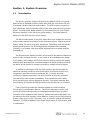
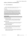
1.1
Introduction
The primary purpose of Alpha’s Engine Control Module (ECM) is to control
and monitor an AlphaGen Auxiliary Power Unit (APU) set, such as the CE-3X2
3.0kW and 5.0kW Series Engine-Generators. The ECM is used in conjunction
with a Generator Remote Interface (GRI) PCBA, often referred to as the Power
Board. The ECM/Power Board Assembly is mounted to the top of the EngineGenerator housing, to the left of the ignition battery. The Power Board is
attached to the ECM via three ribbon cables.
The GRI provides power to the ECM, steps down high voltages for the ECM,
and provides interface connectors for the enclosure sensors, engine controller,
battery sense, line sense, and other equipment. Depending upon the standby
powering configuration, the ECM and generator combination are installed
remotely, or co-located, with other Alpha equipment such as power supplies
and batteries.
The Engine Control Module monitors AC line and DC bus status to determine
when to start and stop the APU. In the event of an extended power outage
or low battery bus voltage, the ECM will start the APU to prevent the backup
batteries from discharging to a reduced voltage level which would compromise
the ability of the system to provide a continuous, reliable source of power.
In addition to starting the APU, the ECM monitors the entire system for
abnormal operating conditions such as low engine oil pressure, engine overtemperature, gas leak, enclosure pad shear, etc. If certain abnormal
conditions or alarms are present, the ECM will either prevent the generator
from starting or shut it down immediately. This provides for public safety,
while preventing any serious damage to the APU. The system operator also
has the ability to override the ECM and control the APU manually or remotely.
Finally, the ECM provides the interface between the APU and Alpha
Technologies' communication devices. The ECM is designed to control and
monitor the APU while responding to commands and queries from a system
controller via an isolated RS-485 data bus. Status information and alarms can
be read from the ECM remotely via the data bus, locally from the Light Emitting
Diodes (LEDs) on the unit’s front panel, or by an optically isolated transponder
interface. The ECM is capable of reporting 9 major alarms, 8 minor alarms, and
2 notifications.
744-862-C0-003 Rev.C
TM
13
Engine Control Module (ECM)
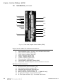
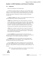
1.1
Introduction, continued
1
3
5
10
2
4
11
6
12
7
8
13
14
15
9
16
Fig. 1-1, Front view, Engine Control Module (ECM)
Engine Control Module LED Indicators and switches:
1.
2.
3.
4.
5.
6.
7.
8.
9.
Communications Input (J4) Note: Pin #1 at bottom of connector.
"Major" Alarm Indicator (Red LED)
"Minor" Alarm Indicator (Red LED)
"Notify" Indicator (Amber LED)
"Comm" Indicator (Green LED)
"System" Indicator (Green LED)
"Run-Auto-Stop" (RAS) switch
"Service/Reset" Push button switch (SW3)
Transponder Interface (J6) Note: Pin #1 at bottom of connector.
GRI Power Board Connectors:
10.
11.
12.
13.
14.
15.
16.
14
Enclosure Alarm Input connector (J10)
Fuel Enclosure Alarm connector (J5)
Interface Input connector from APU (J4)
Inverter battery string connector (J8)
Battery Charger Control Interface (J9) - (5.0kW APU only)
AC generator Voltage, Current connector (J7)
AC Line Input connector (J6) - Connected at all times
TM
744-862-C0-003 Rev.C
Engine Control Module (ECM)
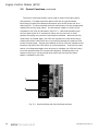
1.1
Introduction, continued
7
8
RUN
AUTO
STOP
SRVC
RESET
Fig. 1-2, Run/Auto/Stop and Service/Reset switches
Ignition
Battery
Shelf
Engine
Generator
Fig. 1-3, Location of Engine Control Module (ECM)
within the Engine-Generator Cabinet.
744-862-C0-003 Rev.C
TM
15
Engine Control Module (ECM)
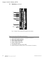
1.1
Introduction, continued
GRI
(Power Board)
Engine Control Module
(ECM) PCB
J2
10
11
J2
1
J1
3
J1
12
5
13
4
6
7
J3
J3
14
2
8
15
15
16
9
Fig.1-4 Open view, ECM Printed circuit boards
Engine Control Module LED Indicators and switches:
1.
2.
3.
4.
5.
6.
7.
8.
9.
Communications Input (J4) Note: Pin #1 at bottom of connector.
"Major" Alarm Indicator (Red LED)
"Minor" Alarm Indicator (Red LED)
"Notify" Indicator (Amber LED)
"Comm" Indicator (Green LED)
"System" Indicator (Green LED)
"Run-Auto-Stop" switch
"Service/Reset" Push button switch (SW3)
Transponder Interface (J6) Note: Pin #1 at bottom of connector.
GRI Power Board Connectors:
10.
11.
12.
13.
14.
15.
16.
16
Enclosure Alarm Input connector (J10)
Fuel Enclosure Alarm connector (J5)
Interface Input connector from APU (J4)
Inverter battery string connector (J8)
Battery Charger Control Interface (J9) - (5.0kW APU only)
AC generator Voltage, Current connector (J7)
AC Line Input connector (J6) - Connected at all times
TM
744-862-C0-003 Rev.C
Engine Control Module (ECM)
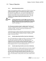
1.2
Theory of Operation
1.2.1
Normal Operating Condition
Under normal operating conditions (no alarms) the ECM's Run-Auto-Stop
(RAS) three-position rocker switch will be in the "center" or AUTO
position as shown in figure 1-2. The ECM has complete control over
the APU while in the AUTO mode. Also, each time the RAS switch is
moved from the STOP position, to the center or AUTO position, the
ECM will run the APU for one minute after a short delay. This is an
indicator to the system operator that the ECM is truly in the AUTO
mode and is fully capable of starting and stopping the APU
automatically.
NOTE:
The Run/Stop switch on the 5.0kW Generator Control
Board MUST be in the center (ECM) position before the
ECM will automatically control the Auxiliary Power Unit.
(On older versions, the center position may be marked
“AUTO” or left blank.)
The APU can be controlled manually by placing the RAS switch in the
“up” or RUN position and the “down” or STOP position. If a system
controller is attached to the ECM via the RS-485 bus, the APU can be
controlled remotely. Similarly, the APU can be started via the
transponder interface on the ECM.
In the AUTO mode, the ECM continuously monitors the AC line voltage,
and DC bus voltage, enclosure sensors, and the APU status. If a fault
occurs, the ECM will determine whether to start or inhibit the APU
based on the type of failure.
1.2.2.
Standby Operating Condition (less than 10 minutes)
If an AC line disturbance or outage is less than 10 minutes, the ECM will
not start the APU unless the battery bus voltage drops below a
programmable threshold (Low DC Bus Level) which defaults to 1.95
Volts per cell or 35.1/46.8/93.6 Volts for 36/48/96 Volt systems
respectively. However, the ECM will notify the system operator of a line
failure via the front panel LED’s (see alarm section). Otherwise, the
ECM will appear to be in a “normal” operating condition.
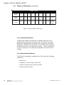
1.2.3.
Standby Operating Condition (more than 10 minutes)
If an AC line disturbance or outage is greater than 10 minutes, the ECM
start delay timer will expire and the ECM will attempt to start the APU.
The ECM will attempt to start the engine 9 times with either a 30
second or a 60 second pause between attempts (See Table 1-1). If
the engine fails to start, the ECM will report an “Engine Over-crank”
alarm. Otherwise, the ECM will start and continue to run the APU until
either a normal shutdown or Major alarm occurs (refer to Alarm section
3.1).
744-862-C0-003 Rev.C
TM
17
Engine Control Module (ECM)
1.2
Theory of Operation, continued
Crank Cycle
Crank
Attempt
1
2
3
4
5
6
7
8
9
Cranking
Engine
15 Sec
15 Sec
15 Sec
15 Sec
15 Sec
15 Sec
15 Sec
15 Sec
15 Sec
Pause
(no crank)
30 Sec
30 Sec
60 Sec
30 Sec
30 Sec
60 Sec
30 Sec
30 Sec
Engine
Overcrank
Alarm
Table 1-1 Normal Mode Crank Cycle
1.2.4. Normal APU Shutdown
The ECM will initiate a normal APU shutdown when AC line is
qualified, DC bus alarm is not active, the 12 minute cool-down
period has elapsed, and the Engine Run command is not active.
Otherwise, the ECM will continue to run the APU until the above
conditions are met or a major alarm occurs. Also, the APU will
run for a minimum of 30 minutes if started due to low DC Bus
voltage.
1.2.5. Abnormal APU Shutdown
The ECM will immediately shutdown the APU under the following
conditions:
•
•
•
•
18
Major alarm
Activation of manual engine stop switch
Receipt of software engine stop command
General generator failure
TM
744-862-C0-003 Rev.C
Engine Control Module (ECM)
1.2
Theory of Operation, continued
1.2.6. ECM Operating Mode Summary
The ECM monitors the status of the AC line and DC bus to make a
determination when to start and stop the generator. The ECM also monitors
APU status while the engine is running and will immediately shut down the unit
if certain alarm conditions are detected. The ECM reports status information
via a parallel data interface and/or an Alpha-Bus serial data (RS-485)
interface.
Any of the following conditions can cause the ECM to start the generator:
1.
2.
3.
4.
5.
6.
7.
Loss of AC line for a period of time in excess of Start Delay
(programmable).
DC bus voltage drops below 1.95 Volts/cell (35.1/46.8/93.6 VDC
for 36/48/96 Volt systems, respectively).
Manual run switch is activated.
Software run command received.
Engine run is commanded via the transponder interface.
A self-test is initiated manually.
An automatic self-test is initiated.
The following conditions are required for normal engine shutdown:
1.
2.
3.
4.
5.
AC line is qualified.
DC bus voltage is greater than nominal +2 Volts (i.e., 50V for a
48V system).
Cool-down period has expired.
Engine Run command is not active.
Engine has run for a minimum of 30 minutes if it started due to low
DC bus voltage.
The following conditions will cause immediate engine shutdown:
1.
2.
3.
Manual engine stop switch is activated.
Software engine stop switch is received.
Any of the following engine alarms become active:
·
·
·
·
·
·
4.
Any of the following system alarms become active:
·
·
·
·
744-862-C0-003 Rev.C
Low oil
Engine over-temperature
Low fuel
Over-speed
Over-crank
Overvoltage
Gas hazard
Pad shear
Water intrusion
General APU failure
TM
19
Engine Control Module (ECM)
This page intentionally blank
20
TM
744-862-C0-003 Rev.C
Engine Control Module (ECM)
Section 2, ECM Indicators and Control Functions
2.1
Indicators
Refer to the illustration on the following page:
The ECM user interface consists of 5 LEDs (2-6), a three-position rocker
switch (7), and a momentary contact, push-button switch (8). The COMM
Interface (1) can be used to attach an Alpha Technologies system controller.
Provisions are made for Transponder connections through the Interface
connector (9).
The Major and Minor alarm LEDs (2,3) are red and reflect the state of the
discrete major and minor alarms monitored by the ECM.
A Major alarm indicates failure of a critical component or some other
situation (pad shear, for example) where the system either has gone offline, or system failure and/or shutdown is imminent. Major alarms cause
the engine to shutdown immediately and generally prevent further
operation. Most major alarms are latched by the ECM. A site check by
service personnel is required to repair the fault and clear the system.
A Minor alarm indicates a system fault which, though not indicative of
imminent system failure or shutdown, requires service attention as the
fault condition could worsen to shut down the system. A site check by
service personnel is recommended.
The amber Notify LED (4) represents status information that is not
significant enough to be classified as an alarm. At present, only two items fit
into this category: AC line status and Engine Service Required.
The COMMunications LED (5) illuminates for two seconds after each
communications session on the Alpha bus. This is a standard that is used
throughout the Alpha bus communications system.
The green SYStem status LED (6) indicates that the microprocessor has
power and is operating normally. This LED flashes at a 1 Hz rate with a 50%
duty cycle. When the ECM is in factory test mode, this LED will flash at a 0.5
Hz rate.
NOTE: Early versions of the ECM (prior to 12/99), the Communications
and System Status functions were swapped.
744-862-C0-003 Rev.C
TM
21
Engine Control Module (ECM)
2.1
Indicators, continued
1
3
5
2
4
6
7
8
9
Pin 1
Fig. 2-1 Engine Control Module LED indicators and switches.
Engine Control Module LED Indicators and switches:
1.
2.
3.
4.
5.
6.
7.
8.
9.
22
Communications Input (note: Pin #1 at bottom of connector)
"Major" Alarm Indicator (Red LED)
"Minor" Alarm Indicator (Red LED)
"Notify" Indicator (Amber LED)
"Comm" Indicator (Green LED)
"System" Indicator (Green LED)
"Run-Auto-Stop" switch
"Service/Reset" Push button switch (SW3)
Parallel Transponder Interface (note: Pin #1 at bottom of connector)
TM
744-862-C0-003 Rev.C
Engine Control Module (ECM)
2.2
Control Functions
Refer to Figure 2-2 on the following page:
The three positions of the rocker switch (7) are RUN - AUTO - STOP (RAS).
The RAS switch is normally left in the center, AUTO, position so that the ECM
has control of the generator set. A minor alarm is indicated when the RAS
switch is not in the AUTO position. The STOP ("down") position is used to
stop or prevent APU operation during maintenance. Placing the RAS switch
in the STOP position for three (3) seconds, then switching back to AUTO
will clear any latched alarms and start the generator if the cause of the
alarm has been corrected. Placing the RAS switch in the RUN ("up") position
will cause the engine to start and run until this switch is released to AUTO.
The engine may not shut down immediately when the switch is returned to
AUTO from RUN, because the ECM’s shutdown criteria must be met in order to
shutdown the engine. Also, each time the RAS switch is placed in the AUTO
position (from the STOP position), the ECM will start and run the APU for one
minute after a short delay.
The service reset push-button switch (8) has two purposes. It resets the
engine service timer when depressed for 5 seconds and can be used to
determine which alarms are active (see "Alarms" section 3.3). The service
interval is a programmable counter within the ECM that defaults to 100 hours
after the initial 25-hour break-in period. When 100 hours of engine run time
elapses, the Service Required notification is set and the notification LED
illuminates. After the engine has been serviced, pressing and holding the
service reset switch for 5 seconds will reset the 100-hour service counter. All
of the LEDs flash, while the switch is depressed, until a five-second timer
elapses at which time all of the LEDs remain on solid until the switch is
released. This provides feedback to the technician, indicating the effective
resetting of the engine service counter.
744-862-C0-003 Rev.C
TM
23
Engine Control Module (ECM)
2.2
Control Functions, continued
The service reset push-button is also used to obtain information about
active alarms. The Major and Minor alarm LEDs are very general and a
technician will need more detailed information upon arrival to the site of an
alarming ECM. To retrieve details about an active alarm, the user presses and
releases the service-reset switch. An active alarm (Major or Minor) will be
indicated by the LEDs as indicated in Figure 3-1. Note that depressing the
service-reset switch for 5 seconds will cause the service timer to clear
possibly disrupting the preventive maintenance schedule. When the servicereset button is pressed again, the LEDs will represent the next active alarm.
Pressing the button when there are no more active alarms will reset the LEDs
to their normal usage. Several quick flashes of all five LEDs will indicate end of
the alarm list before the LEDs return to normal operation. If the service reset
button is not depressed again when an alarm is indicated, the LEDs will return
to normal operation after 30 seconds have elapsed. Resetting alarms via
status monitoring or via the manual stop switch will also clear the alarm
pattern indicated by the LEDs.
RUN
AUTO
STOP
7
SRVC
RESET
8
Fig. 2-2, Run/Auto/Stop and Service/Reset switches
24
TM
744-862-C0-003 Rev.C
Engine Control Module (ECM)
Section 3, ECM Alarms and Notifications
3.1
Alarms Classifications
The ECM is capable of reporting 9 "Major" alarms, 8 "Minor" alarms and 2
"Notifications". The following are detailed descriptions of each.
Major Alarm:
A Major alarm indicates failure of a critical component or some other
situation (pad shear, for example) where the system either has gone offline, or system failure and/or shutdown is imminent. Major alarms
cause the engine to shutdown immediately and generally prevent further
operation. Most major alarms are latched by the ECM. A site check by
service personnel is required to repair the fault and clear the system.
Placing the RAS switch in the STOP position for three (3) seconds,
then switching back to AUTO will clear any latched alarms and start
the generator if the cause of the alarm has been corrected.
MAJOR ALARMS:
Low Oil Pressure (Latching)
Indicates engine oil pressure is below safe limits and operation of the
unit has been suspended. The alarm is cleared when the Reset
command is issued or when the manual stop switch is activated.
Engine Over-Temp
Indicates engine temperature has exceeded safe limits and operation of
the unit has been suspended. The alarm is reset when the engine
temperature falls below safe limits.
Engine Over-speed (Latching)
Indicates engine RPM has exceeded safe limits, and operation of the
unit has been suspended. The alarm is cleared when the Reset
command is issued or when the manual stop switch is activated.
Engine Over-Crank (Latching)
Indicates the failure of the engine to start when commanded to do so.
The alarm is cleared when the Reset command is issued or when the
manual stop switch is activated.
744-862-C0-003 Rev.C
TM
25
Engine Control Module (ECM)
3.1
Alarms Classifications, continued
MAJOR ALARMS (continued):
Alternator Over-voltage (Latching)
The generator set has detected that the alternator output voltage is too
high. Depending on generator type, this likely means that the voltage
regulator or the engine speed governor has failed. Operation of the unit
has been suspended. The alarm is cleared when the Reset command is
issued or when the manual stop switch is activated.
The alternator over-voltage alarm can be triggered in any of three
ways:
1.)
2.)
3.)
The generator controller can signal the ECM that an overvoltage condition exists.
A programmable threshold of 57 VDC (Hi DC Bus Level) is
exceeded for 15 seconds.
A fixed threshold of 2.7V/cell is exceeded for five (5)
seconds. The programmable threshold defaults to 2.5V/cell.
Gas Hazard (Latching)
The concentration of hydrocarbon fuel in the power system’s enclosure
air space has exceeded safe limits or 10%-20% of the Lower Explosive
Limit (LEL) for more than three (3) seconds. APU operation is
suspended. The alarm is cleared when the Reset command is issued or
when the manual stop switch is activated.
Water Intrusion
Water level within the main or fuel enclosure has exceeded safe limits
for generator operation. APU operation is suspended while this alarm
is active. The alarm is reset when the water level falls below maximum
limits.
Pad Shear (Latching)
Indicates that the main or fuel enclosure has shifted from its pad
mounting position. APU operation is suspended. The alarm is reset
when the unit is returned to its original position and the reset command
is issued or when the manual stop switch is activated.
NOTE:
APU will not start if Pad Shear magnet is not
correctly installed below the Pad Shear sensor.
Low Fuel Pressure (Latching - after 5 activations)
Indicates that site fuel supply (Propane-fueled APU only) is
insufficient for extended engine operation. The alarm is reset 5 minutes
after the fuel supply is replenished.
26
TM
744-862-C0-003 Rev.C
Engine Control Module (ECM)
3.1
Alarms Classifications, continued
Minor Alarm:
These alarms indicate a system fault which, though not indicative of
imminent system failure or shutdown, require service attention as the fault
condition could worsen to shut down the system. A site check by service
personnel is recommended.
MINOR ALARMS:
Control Fail (Latching - after 5 activations)
Indicates a control failure between the ECM and the generator set.
Typically this means that the engine did not start or stop when
commanded to do so. The alarm is cleared when the Reset
command is issued or when the manual stop switch is activated.
Alternator Off
This alarm is active if the generator controller has disabled the
alternator output. A generator controller may disable the alternator
output if the output voltage cannot be held above some threshold.
Self-Test Fail (Latching)
Status of most recent generator test. The alarm is cleared when the
Reset command is issued, the manual stop switch is activated or
another Self-Test command is issued.
Low Ignition Battery
Indicates that the generator’s ignition battery voltage has fallen below
11.5VDC. Alarm is cleared when battery voltage rises above 12.0VDC
indicating battery recovery has begun. Note that low ignition battery
voltage is not alarmed during engine cranking.
744-862-C0-003 Rev.C
TM
27
Engine Control Module (ECM)
3.1
Alarms Classifications, continued
Auto Mode Disabled
Indicates the position of the ECM control select switch. When the
Run-Auto-Stop (RAS) switch is in a manual (STOP or RUN) position, the
ECM has no control over engine operation and therefore raises an alarm.
This is a hardware ‘lockout’ input and cannot be changed via status
monitoring.
Tamper
One of the doors on enclosure is open. The alarm clears when the door
is closed.
DC Bus Fault
Indicates that the power system DC bus voltage, as measured at the
ECM, is less than 1.95 volts per cell. This alarm clears automatically
when the bus voltage exceeds 2 volts above nominal (i.e., 50VDC in a
48V system).
Engine Disabled
Command to disable normal operation of the generator set. When set
to DISABLE the engine is shutdown and will remain so under all
conditions. A Minor Alarm indicator will be active if this switch is set to
DISABLE.
The engine is disabled by software after five consecutive "Low Fuel"
alarms or five consecutive "Control Fail" alarms. This alarm is cleared
by issuing a "Reset" command or when the "Manual Stop" switch is
activated.
3.2
Notifications
Additionally, the ECM will report the following "Notification" information.
Line Failure
The ECM’s determination of the state of AC line voltage. Loss of AC
utility input is one of the criteria for starting the generator.
Service Required
Indicates that routine maintenance of the engine - generator is overdue.
This alarm activates when Service Countdown reaches 0. It is cleared
by depressing the service timer reset button for five seconds. (Refer to
Section 5.2 "System Maintenance" for further information) .
28
TM
744-862-C0-003 Rev.C
Engine Control Module (ECM)
3.3
Alarm and Notification Indications
Alarms are indicated in three ways: ECM LEDs, RS-485 communications
and alarm contact closures on ECM transponder interface. Alarm indication
on the ECM LEDs is obtained by pressing the service reset button
momentarily and noting the combination of illuminated LEDs. Pressing the
service reset switch again will reveal the next alarm in the list. When the
alarm list has been exhausted, all LEDs will flash several times and then
return to their normal functions. Placing the RAS switch in the STOP
position for three (3) seconds, then switching back to AUTO will clear
any latched alarms and start the generator if the cause of the alarm
has been corrected. The following figure shows the LED patterns and the
alarms they represent:
Major Alarms
1
2
3
4
5
6
7
8
9
Abbreviation
LO
OT
OS
OC
OV
GH
WI
PS
LP
Major Alarms
10
11
12
13
14
15
16
17
18
19
Abbreviation
CF
AO
TF
IB
AD
TP
DC
ED
LF
SR
Major
Minor
Notify
Comm
System
Major
Minor
Notify
Comm
System
Fig. 3-1 Major, Minor Alarm Indications, and Notifications
(LEDs as displayed on the ECM)
1.
2.
3.
4.
5.
6.
7.
8.
9.
Low Oil Pressure (LO)*
Engine Over-Temp (OT)
Engine Over-Speed (OS)*
Engine Over-Crank (OC)*
Alternator Over-Volt (OV)*
Gas Hazard (GH)*
Water Intrusion (WI)
Pad Shear (PS)*
Low Fuel Pressure (LP)***
Legend:
744-862-C0-003 Rev.C
*
**
***
=
=
=
10.
11.
12.
13.
14.
15.
16.
17.
18.
19.
Control Fail (CF)***
Alternator OFF (AO)
Self-Test Fail (TF)*
Low Ignition Battery (IB)
Auto-mode Disabled (AD)
Tamper (TP)
DC Bus fault (DC)
Engine Disable (ED)
Line Failure (LF)**
Service Required (SR)**
Latching Alarm
Notifications
Alarm “latches” after 5 activations
TM
29
Engine Control Module (ECM)
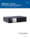
3.4
ECM Transponder Interface
The ECM also provides a transponder interface for remote status
monitoring as shown in figure 2-1, item 9. The transponder interface consists
of a 12-position terminal block with 8 optically-isolated output signals and one
switch closure input signal. The wiring diagram for the transponder interface
is shown in Figure 3-2, with the following signals mapped to the transponder
interface terminal block as shown in below.
PIN
INPUT / OUTPUT
DESCRIPTION
ACTIVE STATE
1
Output
M ajor Alarm (note 1)
Open with respect to Pin 9
2
Output
M inor Alarm (note 1)
Open with respect to Pin 9
3
Output
Engine Alarm (note 3)
Open with respect to Pin 9
4
Output
Gas Hazard
Open with respect to Pin 9
5
Output
Test Fail
Open with respect to Pin 9
6
Output
Enclosure Alarm (note 4)
Open with respect to Pin 9
7
Output
Engine Status
(Running, Stopped)
Closed to Pin 9
8
Output
Tam per
Closed to Pin 9
9
Output Common
10
Input
Engine Run
11
Ground
Engine Run Return
12
Connect to Pin 11
To Be Determined
Table 3-1 ECM Transponder interface
Notes:
1. Major Alarms:
Low Oil Pressure
Engine over-temperature
Engine Overspeed
Overcrank
Output Over-voltage
Low Fuel
Water Intrusion
Pad Shear
Gas Hazard
3. Engine Alarms:
Low oil pressure
Engine over-temperature
Engine Overspeed
Overcrank
Engine disabled by software
4. Enclosure Alarms:
Water Intrusion
Pad Shear
2. Minor Alarms
ECM Control Fail
Alternator OFF (at the time
it should be ON)
Self-test failed
Low Ignition Battery
ECM Run/Auto/Stop switch
not in AUTO position
Tamper
DC bus voltage out of range
Engine disabled by software
Engine Service Required
30
TM
744-862-C0-003 Rev.C
Engine Control Module (ECM)
3.5
Standard ECM-Transponder Interconnection
PIN 1, W1, MAJOR ALARM (Red wire)
PIN 2, W2, MINOR ALARM (Green wire)
PIN 3, W3, ENGINE ALARM (Gray wire)
PIN 4, W4, GAS HAZARD (Brown wire)
PIN 5, W5, TEST FAIL (Blue wire)
PIN 6, W6, ENCLOSURE ALARM (White/Red wire)
PIN 7, W7, ENGINE STATUS (Yellow wire)
PIN 8, W8, TAMPER (White wire)
1
2
3
4
5
6
7
8
9
10
11
12
PIN 9, W9, OUTPUT COMMON (Black wire)
PIN 10, W10, ENGINE RUN (Orange wire)
PIN 11, W11, ENGINE RUN RETURN (White/Black wire)
Not Used
Fig. 3-2 Standard Transponder-to-ECM interconnect cable, collocated applications
USER - SUPPLIED
15
CONDUCTOR BELDEN CABLE
RED
BLACK
BLK W / W HT
1
2
3
4
5
6
7
8
9
10
11
12
GRN W / W HT
GRN W / BLK
BLUE
GREEN
RED
GREEN
GRAY
BROWN
BLUE
W HITE / RED
YELLOW
O RANGE
W HITE
WH ITE
BLACK
W HT W / BLK
BLU W / WHT
RED W / BLK
O RANGE
W HT / BLK
N OT U SED
Fig. 3-3 Standard Transponder-to-ECM interconnect cable, remote applications
744-862-C0-003 Rev.C
TM
31
Engine Control Module (ECM)
3.5
Standard ECM-Transponder Interconnection, cont’d
Top view
Plug-side view
Terminal 1
Terminal 1
Wire-insertion-side view
Terminal 1
Fig. 3-4 ECMconnector arrangement
1
2
3
4
Unused
SCM COMM
PIN 2, BLACK Wire
PIN 3, RED Wire
Unused
Fig. 3-5 SCM-to-ECM interconnect cable
Plug-side view
Top view
Terminal 1
Terminal 1
Wire-insertion-side view
Terminal 1
Fig. 3-6 ECM-to-SCM connector arrangement
32
TM
744-862-C0-003 Rev.C
Engine Control Module (ECM)
3.6
Transponder System Block Diagram
Alpha
XMS2
USM-2
Transponder
Enclosure
Tamper
Switc
h
USM
Interface
Connector
APU Interface
'Alpha'
Side
'Transponder'
Side
Power Supply
Enclosure
Transponder
to
ECM Interface cable
Enclosure
Sensors
Alpha
ECM
Battery Pack, 36 VDC or 48VDC
Auxiliary Power Unit
Enclosure CE-3X2
Alpha
Auxiliary
Power Unit
(APU)
Pin 1 on bottom
744-862-C0-003 Rev.C
TM
33
Engine Control Module (ECM)
Section 4, ECM Configuration/System Interface
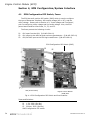
4.1
ECM Configuration DIP Switch, Fuses
The ECM has an 8 position DIP switch (SW5) which is used to configure
the type of Generator Interface, APU output voltage (AC or DC), and the
utility voltage. Please refer to Section 4.4, "Input Voltage and Line Sense",
prior to configuring utility voltage and line sense voltage. Also, the ECM
power board contains three fuses, F1, F2, and F3.
The fuses protect the following circuits:
F1:
F2:
F3:
12V input from the APU. (P/N 460-204-10)
12V output to the APU fan and enclosure gas detector. (P/N 460-205-10)
120/240 VAC input to the ECM logic transformer. (P/N 460-166-10)
ECM Configuration DIP Switch (SW5)
J2
F2
J2
J1
J1
F1
J3
J3
F3
GRI (Power Board)
Engine Control Module
(ECM) PCB
Fig. 4-1 ECM Configuration DIP Switch and fuse locations
Fuses and Switches:
F1
F2
F3
SW5
34
1.5A, 250V (Slo-Blo)
1.0A, 250V (Slo-Blo)
250mA, 250V (Slo-Blo)
Configuration DIP switch
TM
744-862-C0-003 Rev.C
Engine Control Module (ECM)
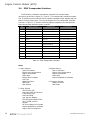
4.2
ECM Configuration
The ECM configuration is required for interface type, output voltage,
input voltage and reserved functions. The following should be used to
configure the ECM:
E C M S w i tc h 5 S e t t in g s
1
2
M e a n in g
3
4
5
6
7
8
1 = ON, 0 = O FF
N o n s ta n d a r d G R I in te r fa c e
( 7 .5 k W S e r ie s )
0
1
S ta n d a r d G R I in te r fa c e , C E - 3 X 2
0
0
0
In v a lid o u tp u t v o lta g e c o n fig u ra tio n
0
0
1
2 4 V D C O u tp u t
0
1
0
3 6 V D C O u tp u t
0
1
1
4 8 V D C O u tp u t
1
0
0
9 6 V D C O u tp u t
1
0
1
1 2 0 V D C O u tp u t
1
1
0
2 0 8 V D C O u tp u t
1
1
1
2 4 0 V D C O u tp u t
0
0
In v a lid in p u t v o lta g e c o n fig u r a tio n
0
1
1 2 0 A C in p u t
1
0
2 0 8 3 -p h a s e in p u t
1
1
2 4 0 V A C in p u t
0
0
N o a ffe c t
0
1
N o a ffe c t
1
0
1
1
E C M D r iv e s s ta r te r w ith th e " E n g in e S ta r t"
S ig n a l.
" E n g in e S ta r t" S ig n a l b e c o m e s
" E n g in e R u n " a n d is h e ld lo w b y E C M
0
A u to te s t tu r n e d O F F .*
1
A u to te s t s e q u e n c e e n a b le d w ith 1 4 - d a y te s t
in te r v a l
Table 4-1 ECM switch configurations.
(Switch settings shown below are for a CE-3X2 with 120 VAC input and 36VDC output.)
*NOTE:
Programming parameters that affect the Autotest
feature via Status Monitoring will override this switch
setting.
Input voltage configuration
Output voltage configuration
Interface
Engine Start/Run Signal
Enable Autotest
ON
1 2 3 4 5 6 7 8
Fig. 4-2 SW5, ECM PCBA
(Alpha p/n 704-630-xx-xxx)
744-862-C0-003 Rev.C
TM
35
Engine Control Module (ECM)
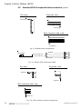
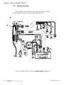
4.3
System Interface
The illustration below shows the interconnection between the ECM,
engine-generator controller, and enclosure safety sensors.
PIN 1
Fig. 4-3 ECM/APU Interconnection, 2.7kW/3.0 kW configuration
36
TM
744-862-C0-003 Rev.C
Engine Control Module (ECM)
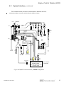
4.3
System Interface, continued
The illustration below shows the interconnection between the ECM,
engine-generator controller, and enclosure safety sensors.
PWR-GRI
ECM
J10
GHD
PLUG
ALARM
INTERFACE
PIN 1
LFP
PLUG
PAD
SHEAR
DOOR
OPEN
WATER
INTRUSION
J4
GAS
APU CONTROL
INTERFACE
SOLENOID
ALAR
M
GSC
RESET
J8
CHARGER CONTROL
GAS
MODEL HIC
DETECTOR
Chestec Corporation
Port Washington, NY
OUTPUT
842
GAS
SENSOR
DC
POWER
RED
BLK
RED
PLUG
READ
Y
INV BATTERY
SENSE
LOW
FUEL
PRESSURE
FAN
2
J
2
1 3
1
PIN 1
2 4
J6
LINE
SENSE
APU
CONTROL
PCB
+
-
POS
NEG
POS
NE
G
12 pin
AMP
6 pin
ML
INTERFACE
+
LINE
SENSE
BATTERY HEATER
OPTION - 120V
20 pin
AMP
DCNDCP
120V
NEU
T
ALARM
POS
NE
G
IGNITION
BATTERY
-
DC OUTPUT BUS
2 pin
MML
-
BLOCK HEATER
OPTION
IG
BAT
N
T
+
15 pin
MML
DC
OUT
See Alpha 5 Manual,
Kohler Power Systems document
# TP-6076, 12/99
ENGINE ALTERNATOR
COMPARTMENT
Fig. 4-4 ECM/APU Interconnection, 5.0 kW configuration
744-862-C0-003 Rev.C
TM
37
Engine Control Module (ECM)
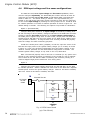
4.4
ECM input voltage and line sense configurations
The ECM has 120/240VAC input voltage and line sense capabilities, which
must be configured separately. The ECM PCBA part number 704-630-XX must be
configured for 120/208/240VAC line sense via DIP Switch SW5-5 and SW5-6 as
shown in table 4-1. The default setting is 120VAC. The logic transformer (T1)
located on the GRI power board part number 704-634-XX must also be configured
for the correct input voltage by installing zero ohm jumpers R1-R4. Install R1 & R2
for 120VAC operation or R3 & R4 for 240VAC operation as shown in figure 4-4. The
default setting is 120VAC. The following two options are provided for clarification:
Option 1 (Recommended)
Configure ECM power board for an input voltage of 120VAC by installing R1 &
R2 and removing R3 & R4 (default). Configure DIP SW5 on the ECM board for either
120VAC or 240VAC line sense depending on the input voltage configuration of
the XMS2 power supplies being used. In other words, always power the ECM with
120VAC and set DIP SW-5 for the input voltage of the XMS2 power supplies being
used (120VAC or 240VAC). As long as SW-5 is set correctly, the ECM will properly
scale the voltage for status monitoring purposes.
Install the 120VAC power cable (y-adapter) to both the input line sense of the
ECM and the input power to the ignition battery charger (L1 to neutral) as shown
in Figure 4-3. This is the preferred configuration since the battery charger is only
rated for 120VAC operation and the ECM’s default configuration is 120VAC. The
120VAC ignition battery charger is only used on the 2.7/3.0kW APUs.
Note: The ECM will properly sense a line loss on a 240VAC (L1-L2) system even
though it’s only monitoring 120Vac (L1-Neutral) as long as SW-5 is set for 240VAC.
This is based on the fact that the ECM is monitoring the secondary winding of a
centered tapped single-phase transformer from utility power.
Option 2
Configure the power board jumpers R3 and R4 and the DIP SW-5 on the ECM
for 240VAC operation. Install a 240VAC line sense cord for the ECM and a separate
120VAC power cord for the ignition battery charger. When R1 and R2 are installed,
VAC=120. When R3 and R4 are installed, VAC=240.
F3
J6
120/240VAC
AC LINE
SENSE
250mAMP 250V SB
1
2
R1
120V
T1
12V
R3
120/240V
240V
R2
12V
120V
R4
240 V
Fig. 4-5 ECM Power Board
(p/n 704-634-XX)
38
TM
744-862-C0-003 Rev.C
Engine Control Module (ECM)
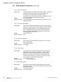
4.5
ECM System Parameters
The following is a listing of programmable parameters used by the ECM.
They may be changed via the Telecom Power Monitor (TPM). Refer to the
Telecom Power Monitor Technical Manual (p/n 744-781-B0) for additional
information.
4.5.1 Low DC Bus Level
Description:
Range:
Default setting:
If the power system battery voltage goes below this
threshold voltage for a certain period of time, the
ECM will start the generator.
0V to 127VDC
1.95 volts/cell
4.5.2 High DC Bus Level
Description:
Range:
Default setting:
If the power system battery voltage goes above this
threshold voltage for a certain period of time, the
ECM will shut down the generator.
0V to 127VDC
2.5 volts/cell
4.5.3 Service Interval
Description:
Range:
Default setting:
Number of engine run hours between required
services.
0 to 65535 hours
100 hours
4.5.4 Service Countdown
Description:
Range:
Default setting:
The number of engine run hours remaining until the
next periodic maintenance is required. This
parameter is reset to Service Interval when the
service timer reset button is depressed for at least
five seconds. Run time since last service is simply
Service Interval minus Service Countdown.
0 to 65535 hours
N/A
4.5.5 Total Engine Runtime
Description:
Range:
Default setting:
744-862-C0-003 Rev.C
This counter keeps track of total in-service hours on
the generator set. It can be programmed to an
initial value that matches a mechanical hour-meter
that is often found on the generator’s prime mover or
it can be used in place of such a meter.
0 to 65535 hours
N/A
TM
39
Engine Control Module (ECM)
4.5
ECM System Parameters, continued
4.5.6 Auto-test Interval
Description:
Range:
Default setting:
Interval between automatic self tests in days. Auto-test
Countdown is reset to this value (multiplied by 24
hours) when this parameter is written or upon
completion of an automatic self test. Setting this value
to zero will disable the automatic self-test.
0 to 65535 days
0 days (automatic self tests disabled) See table 4-1 for
Autotest enable.
4.5.7 Auto-test Countdown
Description:
Range:
Default setting:
The number of hours remaining until the next automatic
self-test. This parameter is an indicator but also can be
used to program the time of the next automatic selftest. Subsequent tests will occur Auto-test Interval
days later at the same time of the day (if a real time
clock is installed in the ECM).
0 to 65535 hours
N/A
4.5.8 Auto-test Duration
Description:
Range:
Default setting:
The number of minutes that the engine will run when a
test is requested.
0 to 65535 minutes
10 minutes
4.5.9 Start Delay
Description:
Range:
Default setting:
The period of time between detection of utility failure
and start of the engine - generator. If utility power
returns before the start delay timer expires (counts
down to 0), the timer will start to count up after 30
minutes and continue to increment 1 count per minute
until it returns to the Start Delay value.
0 to 65535 seconds
600 (10 minutes)
4.5.10 Shutdown Delay
Description:
Range:
Default setting:
40
TM
Cool-down period between determination by the ECM
that the generator can be shutdown and the time actual
shutdown occurs.
0 to 65535 seconds
720 (12 minutes)
744-862-C0-003 Rev.C
Engine Control Module (ECM)
Section 5, System Self-test and Maintenance
5.1
Self-Test
Generator testing can be initiated in four ways:
1.
2.
3.
4.
The ECM can be programmed to periodically run an automatic test
(Default OFF).
A Self-Test can be commanded via status communications.
Momentary activation of the Engine Run command will cause the
ECM to effectively run a test. Note that this method is the least
desirable because the Self-Test Fail alarm will not be set if an
alarm condition arises.
A one-minute automatic test is performed when the manual control
switch is returned to Auto from Stop.
Generator testing consists of starting and running the generator for a
programmable period of time (the default test duration is 10 minutes). The
ECM monitors all engine-related signals and will declare a self-test as failed if
any of the following alarms activate during the test:
•
•
•
•
•
•
•
•
•
•
Low Oil Pressure
Engine Over-temperature
Engine Over-speed
Engine Over-crank
Low Fuel
Alternator Over-voltage
ECM Control Failure
Alternator Not On
Low Ignition Battery
Low DC Bus Voltage
The ECM will not start a self-test if the engine is disabled, the stop switch is
asserted, or the engine is already running.
744-862-C0-003 Rev.C
TM
41
Engine Control Module (ECM)
5.1
Self-Test, continued
If AC line should fail during a test, the test will terminate normally but the
engine will continue to run until line returns. If the test fails because the DC
Bus alarm activates, the test will terminate, the self-test fail alarm will
activate but the generator will continue to run until the DC Bus alarm clears.
The Self-Test Fail alarm may be cleared via a reset command or by
successfully running a subsequent test.
The programmable, internal ECM variables listed below control automatic
self-tests.
Auto-Test Interval
This feature represents the number of days between automatic tests.
Programming this variable to 0 disables the automatic test feature (0 is
the default value).
Auto-Test Countdown
This countdown timer is monitored by the ECM to determine when the
next automatic test should be initiated. Although this timer is normally
used as a status indicator, it can be used to set the start time for the
next auto-test. For example, if the user wants to start the automatic
test sequence at 12:30pm and it is presently 10:15am, they can wait
until 10:30 and program Auto-Test Countdown to 2 hours. Subsequent
tests will begin at nearly the same time of day so long as the ECM
doesn't lose power in the interim. The ECM sets Auto-Test Countdown
whenever the Auto-Test Interval is changed. Thus, if the Auto-Test
Interval is programmed to 10 days, the ECM will set Auto-Test
Countdown to 240 hours.
Auto-Test Duration
The length of each Auto-test is measured in minutes. The default test
duration is 10 minutes. The test duration may be set between 10 and
120 minutes.
Manually enabling the Autotest feature
Switch SW5-8 is used to enable the autotest feature with a 14-day test
interval. The first autotest will begin 14 days from the time the ECM is
powered up with the configuration switch changed from 0 to 1 (OFF to
ON). To disable the autotest sequence, place switch SW5-8 in the OFF
position and restart the ECM. It is important to understand that upon
power up, the ECM looks for a change in the switch position before it
changes the test control parameters. (Please refer to Fig. 4-2)
42
TM
744-862-C0-003 Rev.C
Engine Control Module (ECM)
5.2
System Maintenance
The ECM monitors time between periodic maintenance of the enginegenerator. The Service Interval internal ECM variable represents the number
of hours of engine-run-time between periodic services. When the engine runs
for a number of hours equal to Service Interval, the ECM sets the Service
Required Alarm and turns on the amber notification LED. The default value of
Service Interval is 100 hours but may be programmed from 0 to 250.
Service Due represents the number of engine run time hours before the
next periodic maintenance will be required. Pressing and holding the servicereset switch for 5 seconds resets the service counter and Service Due is
updated with the current value of the service interval.
An exception to the standard Service Interval occurs when the engine is
new. At 25 hours of Engine Run Time, the ECM will set the Service Required
flag. 25 hours represents the break-in period of the engine, which should be
serviced at this point. Note that if a service-reset is performed before the
Engine Run Time counter reaches 20 hours, the Service Required flag will still
be set at 25 hours. If, on the other hand, a service-reset is issued when the
engine has run for more than 20 hours, the Service Countdown will be set to
Service Interval.
NOTE:
744-862-C0-003 Rev.C
5.0kW APUs are shipped with synthetic oil which does not
require changing after the initial 25 operational hours. The oil
should be changed after each 72- to 100-hour period of
continuous operation in accordance with the generator
manufacturer’s owners manual. Exact times will vary as a
function of temperature and operating conditions.
TM
43
Engine Control Module (ECM)
This page intentionally blank
44
TM
744-862-C0-003 Rev.C
Engine Control Module (ECM)
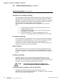
Engine Control Module Alarm Table
Remove page and use for quick reference
Alarms are indicated in three ways: ECM LEDs, RS-485 communications
and alarm contact closures on ECM transponder interface. Alarm indication
on the ECM LEDs is obtained by pressing the service reset button
momentarily and noting the combination of illuminated LEDs. Pressing the
service reset switch again will reveal the next alarm in the list. When the
alarm list has been exhausted, all LEDs will flash several times and then
return to their normal functions. Placing the RAS switch in the STOP
position for three (3) seconds, then switching back to AUTO will clear
any latched alarms and start the generator if the cause of the alarm
has been corrected. The following figure shows the LED patterns and the
alarms they represent:
Major Alarms
1
2
3
4
5
6
7
8
9
Abbreviation
LO
OT
OS
OC
OV
GH
WI
PS
LP
Major Alarms
10
11
12
13
14
15
16
17
18
19
Abbreviation
CF
AO
TF
IB
AD
TP
DC
ED
LF
SR
Major
Minor
Notify
Comm
✄
System
Major
Minor
Notify
Comm
System
Refer to the list below for the type of alarm indicated by the LEDs.
1.
2.
3.
4.
5.
6.
7.
8.
9.
Low Oil Pressure (LO)*
Engine Over-Temp (OT)
Engine Over-Speed (OS)*
Engine Over-Crank (OC)*
Alternator Over-Volt (OV)*
Gas Hazard (GH)*
Water Intrusion (WI)
Pad Shear (PS)*
Low Fuel Pressure (LP)***
Legend:
744-862-C0-003 Rev.C
*
**
***
=
=
=
10.
11.
12.
13.
14.
15.
16.
17.
18.
19.
Control Fail (CF)***
Alternator OFF (AO)
Self-Test Fail (TF)*
Low Ignition Battery (IB)
Auto-mode Disabled (AD)
Tamper (TP)
DC Bus fault (DC)
Engine Disable (ED)
Line Failure (LF)**
Service Required (SR)**
Latching Alarm
Notifications
Alarm “latches” after 5 activations
TM
45
Engine Control Module (ECM)
This page intentionally blank
46
TM
744-862-C0-003 Rev.C
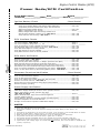
Engine Control Module (ECM)
Power Node/ECM Certification
Power Node Location___________Node____________ Model#____________
Technician______________Date ____________
Serial #___________
Ignition Battery Check
(Record Results)
Verify correct Ignition Battery and Charger cables attachment ........................
Verify Battery Terminal surfaces clean, tight, and covered with
approved corrosion inhibitor (NCP-2) ...........................................................
Battery Voltage Range 12.5-14.1Vdc. ...........................................................
Battery Charger LED is OFF when charge reaches 14.1V
and ON when discharge reaches 13.1V *See note 1 .................................
Verify Enclosure Fan Running? *See note 2 ..............................................
Pass / Fail
Pass / Fail
Actual= _____
Pass / Fail
Pass / Fail
ECM Interface Checks
Line sense Voltage. *See note 3
..................................................................
Line sense Frequency Range 60Hz +/- 1Hz. .......................................................
Verify all connectors correctly installed and locked into place. ..................................
Run-Auto-Stop (RAS) rocker switch set to Auto. *See note 4 ............................
Verify Pad Shear Magnet is correctly installed. .......................................................
Verify Gas Detector is correctly installed. ..............................................................
Verify Water Intrusion sensor is correctly installed. ................................................
Actual = ________
Actual = ________
Pass / Fail
Pass / Fail
Pass / Fail
Pass / Fail
Pass / Fail
✄
ECM Alarm Verification
ECM has “Heart Beat”? *See note 5 ...............................................................
Verify no Major alarms are reported.
...............................................................
Verify the only Minor alarm reported is “Tamper” (Enclosure Door Open). ................
Water Intrusion Sensor (Hold float up to activate major alarm). ...............................
Pad Shear Sensor (Place metal object between sensors to activate major alarm). ..................
Gas Detector (Use a cloth moistened with Isopropyl alcohol to active major alarm). ...............
Verify Line Failure Notification by disconnecting Line Sense. *See Note 6 ...........
Verify DC Bus Fault alarm by disconnecting Battery Sense. *See Note 7 ...........
Generator Functional Verification
Pass
Pass
Pass
Pass
Pass
Pass
Pass
Pass
/ Fail
/ Fail
/ Fail
/ Fail
/ Fail
/ Fail
/ Fail
/ Fail
(Record Results)
Remove page and use for quick reference
Verify oil clean and filled to capacity.
...............................................................
Verify air filter clean and installed.
...............................................................
Verify no oil leakage from oil filter, drain plug, and oil fill tube. ................................
Perform one minute self-test. *See note 4 .......................................................
Engine does not “hunt” excessively during idle/no load conditions. ...........................
Enclosure properly grounding.
...............................................................
Pass
Pass
Pass
Pass
Pass
Pass
/ Fail
/ Fail
/ Fail
/ Fail
/ Fail
/ Fail
Power Supply Verification
XMS2 Power Supply checked per section 5 of the operator’s manual ........................
Battery pack voltage (no load, generator off) range.
*See note 8, note 9
...............................................................
Battery Terminals clean, tight, and covered with approved
corrosion inhibitor (NCP-2).
...............................................................
Service Entrance, Enclosure, and Power Supply grounded properly. ..........................
Successful completion of 10 minute Self-test. ........................................................
No Major or Minor alarms reported on XMS2 Smart Display. ....................................
Pass / Fail
Actual =________
Pass
Pass
Pass
Pass
/
/
/
/
Fail
Fail
Fail
Fail
NOTES:
1 . Some older 5kW chargers do not have an LED.
2 . During initial installation, the fan will completely discharge the ignition battery if utility power is not
available.
3 . The ECM can be configured for 120 or 240 VAC line sense. Refer to Section 4.4 of the ECM Manual for details.
4 . Each time the RAS switch is placed in Auto, a one minute self-test is performed.
5 . ECM’s built after 12/99 use a flashing SYS LED in lieu of the COM LED for the “Heart Beat”.
6 . The generator will not start unless a line failure is greater then 10 minutes.
7 . The generator will start immediately and run for a minimum of 30 minutes (Use RAS to stop Gen).
8 . The difference between any battery in the string should not exceed 0.3 Vdc under load (XMS2 self-test).
9 . Typical battery pack voltage ranges are 39.6-42.3Vdc, 52.8-56.4Vdc, and 105.6-112.8Vdc for 36/48/96 volt
systems, respectively.
744-862-C0-003 Rev.C
TM
47
This page intentionally blank
Notes:
Investigate the
of Alpha @ www.alpha.com
UNITED STATES
ASIA PACIFIC
LATIN AMERICA
Alpha Technologies
3767 Alpha Way
Bellingham, WA 98226
Tel: (360) 647-2360
Fax: (360) 671-4936
Web: www.alpha.com
CANADA
Alpha Technologies
7033 Antrim Ave.
Burnaby, B.C. V5J 4M5
Tel: (604) 430-1476
Fax: (604) 430-8908
UNITED KINGDOM
Alpha Technologies
Cartel Business Estate
Edinburgh Way
Harlow, Essex CM20 2DU
Tel: +44-1279-422110
Fax: +44-1279-423355
GERMANY
Alpha Technologies
Hansastrasse 8
D-91126 Schwabach
Tel: +49-9122-997303
Fax: +49-9122-997321
MIDDLE EAST
Alphatec
P.O. Box 6468
3307 Limassol, Cyprus
Tel: +357-5-375675
Fax: +357-5-359595
AUSTRALIA
Alpha Technologies
8 Anella Ave., Unit 6
Castle Hill, NSW 2154
Tel: +61 (0)2 9894-7866
Fax: +61 (0)2 9894-0234
Due to continuing product improvements, Alpha reserves the right to change specifications without notice.
Copyright © 2003 Alpha Technologies, Inc. All rights reserved. Alpha is a registered trademark of Alpha Technologies. 744-862-C0-003 Rev. C.