1
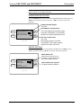
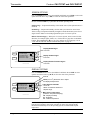
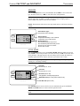
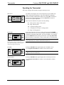
Crestron CHV-TSTAT & CHV-THSTAT Thermostats Operations and Installation Guide This document was prepared and written by the Technical Documentation department at: Crestron Electronics, Inc. 15 Volvo Drive Rockleigh, NJ 07647 1-888-CRESTRON All brand names, product names and trademarks are the property of their respective owners. ©2002 Crestron Electronics, Inc. Crestron CHV-TSTAT and CHV-THSTAT Thermostats Contents Quick Installation Reference .....................................................................................................ii Thermostats: CHV-TSTAT and CHV-THSTAT 1 Introduction ............................................................................................................................... 1 Functions and Features ................................................................................................ 1 Heating and Cooling Systems...................................................................................... 2 Specifications .............................................................................................................. 3 Physical Description.................................................................................................... 4 Industry Compliance ................................................................................................... 6 Setup .......................................................................................................................................... 7 Network Wiring........................................................................................................... 7 Identity Code ............................................................................................................... 7 Wiring Diagrams ......................................................................................................... 8 Installation ................................................................................................................. 12 Thermostat Setup....................................................................................................... 14 Operating the Thermostat .......................................................................................... 18 Programming Software ............................................................................................................ 20 Programming with the Crestron D3 Pro .................................................................... 21 Programming with SIMPL Windows ........................................................................ 21 Problem Solving ...................................................................................................................... 32 Troubleshooting......................................................................................................... 32 Further Inquiries ........................................................................................................ 33 Firmware Upgrades ................................................................................................... 33 Future Updates .......................................................................................................... 33 Appendix A: Glossary ............................................................................................................. 34 Appendix B: About Heat Pumps.............................................................................................. 35 Return and Warranty Policies .................................................................................................. 36 Merchandise Returns / Repair Service ...................................................................... 36 CRESTRON Limited Warranty................................................................................. 36 Operations and Installation Guide – DOC. 8163 Contents • i Thermostats Crestron CHV-TSTAT and CHV-THSTAT Quick Installation Reference 1. Select a suitable location and run the connecting wires from the heating/cooling system and the Cresnet system. Refer to page 5 for a description of the thermostat connectors. Refer to page 7 for Network wiring details. Use the appropriate wiring diagram: • Heating or Cooling System Powered (Refer to page 8). • Separately Powered (Refer to page 9). • Two Wire Heat Only (Refer to page 9). • Three Wire Heat Only with Fan (Refer to page10). • Single Stage Heat/Cool (Refer to page 10). • Single Stage Heat Pump (Refer to page 11). • Two Stage Heat Pump (Refer to page 11). 2. Separate the thermostat from the backplate to expose the connections and mounting holes. 3. Mount the thermostat backplate directly to the wall with wall anchors (not provided) and screws (not provided) or to a single-gang box (not provided) mounted horizontally, and connect the wiring. Refer to page 12 for detailed mounting instructions and page 5 for detailed connector information. 4. Install the thermostat on the backplate and setup the thermostat (Refer to page 14). 5. Configure the thermostat (Refer to Operating the Thermostat on page 18). ii • Contents Operations and Installation Guide – DOC. 8163 Crestron CHV-TSTAT and CHV-THSTAT Thermostats Thermostats: CHV-TSTAT and CHV-THSTAT Introduction Functions and Features The CHV-TSTAT and CHV-THSTAT series are wall-mounted universal thermostats that can be part of a Crestron Home™ total control system. The thermostats are capable of controlling one or two-stage heating and cooling systems. Each thermostat is available in three colors: almond, black and white. The suffix ‘A’, ‘B’, and ‘W’, respectively denotes color, i.e., CHV-TSTATB is a black unit. For simplicity within this guide, color suffix is omitted and the designations CHV-TSTAT and CHVTHSTAT are used except where noted. Functional Summary • • • • • • • • User adjustable temperature and/or humidity control of one and two-stage heating and cooling systems 128 x 64 transflective 2.75 inch (6.99 cm) LCD display Fahrenheit or Celsius indication Four-front panel buttons for setup, configuring and temperature/humidity adjustments Back light (with each button press) for night viewing Supports up to two remote temperature and/or temperature/humidity sensors. Future firmware releases will support up to four remote sensors per thermostat Operates as a stand-alone device or in a Cresnet System Extended functionality as a Cresnet device for lighting control, alarms, etc. The CHV-TSTAT provides temperature control, while the CHV-THSTAT provides temperature and humidity control. Temperature and humidity information is provided through a transflective LCD display. Four front panel buttons and the LCD display provide temperature and/or humidity indication and control, current system status, and current fan mode. The LCD also provides status indicators denoting when heat, cool, humidity or fan outputs are energized; a message indicator, so users know when a message is waiting to be read; a net indicator to denote when the network is active and a hold indicator that identifies when the thermostat is overriding the Cresnet temperature set point commands. Operations and Installation Guide - DOC. 8163 Thermostats: CHV-TSTAT and CHV-THSTAT • 1 Thermostats Crestron CHV-TSTAT and CHV-THSTAT Remote Sensors The current firmware release supports the addition of two optional remote sensors: temperature only (CHV-RTS) and/or temperature/humidity (CHV-RTHS), for both thermostats. Outdoor conditions can be imported from the optional external sensors CHV-RTS or CHV-RTHS, temperature and temperature/humidity respectively. Subsequent firmware releases will support the addition of up to four optional remote sensors, in any combination, for each thermostat. NOTE: The CHV-TSTAT and CHV-THSTAT allow the user to set a temperature that the heating and/or cooling system maintains. This is called the “Set Point”. Refer to “Operating the Thermostat” on page 18 for more information. NOTE: Installers should have a strong working knowledge of HVAC systems. Heating and Cooling Systems The CHV-TSTAT can control the following heating and cooling systems: • One stage heat • One stage heat, one stage cool • One stage heat, one stage cool: heat pump with auxiliary heat • Two stage heat • Two stage heat, one stage cool • One stage heat, two stage cool • Two stage heat, two stage cool • Two stage heat, two stage cool: heat pump with auxiliary heat NOTE: Two Stage Heating – Unlike traditional furnaces that turn on and run at full capacity with each demand for heating, two-stage heat operates like two separate furnaces to maintain more consistent comfort in your home. The unit starts out running in its first stage, and operates at about 68% of its heating capacity. This reduced capacity is sufficient to warm your home on mild winter days. But when the temperature outside goes very low, the furnace adjusts to full capacity (second stage) to meet the demand for heat within the home. 2 • Thermostats: CHV-TSTAT and CHV-THSTAT Operations and Installation Guide – DOC. 8163 Crestron CHV-TSTAT and CHV-THSTAT Thermostats Specifications The following table provides a summary of specifications for the CHV-TSTAT and CHV-THSTAT. CHV-TSTAT and CHV-THSTAT Specifications SPECIFICATION DETAILS Power Requirements 2 Watts (24 VAC @ 83mA) Heating or Cooling System Supplied Crestron power factor <1Watt (required for Cresnet communication only) Default Network ID 2A Control System Update Files 1,2,3 2-Series Control System Version C2-2004.CUZ or later CEN/CN-TVAV Version 5.10.13V.UPZ or later CNMSX-AV/PRO Version 5.07.05X.UPZ or later CNRACKX/-DP Version 5.07.06W.UPZ or later ST-CP Version 4.00.49S.UPZ or later LCD Display 128 x 64 Transflective 2.75 in (6.99 cm) Screen Viewing Angles Y Dir. (X=0º): +50º (from top) –50º (from bottom) X Dir. (X=10º): +50º (from right) –50º (from left) Humidity Range 0 – 100% Auto Setpoint Range (union of heat and cool setpoint ranges) 38 – 110°F (3 – 43°C) Heat Only Setpoint Range 38 –- 90°F (3 – 32°C) Cool Only Setpoint Range 59 – 110°F (15 – 43°C) Temperature Measurement Range 0 – 110° (-18 – 43°C) 4 Firmware Update Files CHV-TSTAT/CHV-THSTAT CHVTSTAT.xx.UPG or later Update File CHVTHSTAT.x.x.UPG or later Dimensions and Weight Height: 3.75 in (9.50 cm) Width: 5.00 in (12.70 cm) Depth: 1.04 in (2.63 cm) Weight: 5.80 oz (165 g) 1. 2. 3. 4. The latest versions can be obtained from the Downloads | Software Updates section of the Crestron website (www.crestron.com). Refer to NOTE after last footnote. Crestron 2-Series control systems include the AV2, CP2, CP2E, MP2, MP2E, PAC2, PRO2, and RACK2. CNX update files are required for either CNMSX-AV/Pro or CNRACKX/-DP. Filenames for CNX update files have a UPZ extension and ST-CP files are in one EXE or zipped UPZ file. To avoid program problems, make certain you are using the update file with the correct suffix letter (e.g., S, V, W, X). Filenames for CHV update files have a UPG extension and are in one zipped UPG file. The ‘x’ in the file name refers to the version number. NOTE: Crestron software and any files on the website are for Authorized Crestron dealers only. New users may be required to register to obtain access to certain areas of the site (including the FTP site). Operations and Installation Guide - DOC. 8163 Thermostats: CHV-TSTAT and CHV-THSTAT • 3 Thermostats Crestron CHV-TSTAT and CHV-THSTAT Physical Description Refer to the illustrations below and on next page. The CHV-TSTAT and CHVTHSTAT are enclosed in a plastic enclosure with four buttons and an LCD display on the front. The back of the unit has ventilation slots, and holes for mounting the unit and wiring. The ventilation slots must be unobstructed for airflow to the unit. Physical View of CHV-TSTAT and CHV-THSTAT Current Temperature Current Humidity 76 43 o F % 74 F o HEATING HEAT ONLY NET FAULT H1 H2 AX Current Set Point (manual) or Set Point range (auto mode) Current Activity Current Function System Information ON LINE (Cresnet on) HOLD (Cresnet off) NET FAULT (Net down) VIEW MSG (view message) Available Systems 0.47 in (1.18) cm Front and Side Views 3.75 in (9.50) cm MODE VIEW 5.00 in (12.70) cm Rear View 4.630 in (11.76) cm 1.04 in (2.63) cm 1.75 in (4.44 cm) 3.38 in (8.59) cm 3.27 in (8.29) cm 4 • Thermostats: CHV-TSTAT and CHV-THSTAT Operations and Installation Guide – DOC. 8163 Crestron CHV-TSTAT and CHV-THSTAT Thermostats Connection View (Backplate, view from the front with cover removed) Z G 24V Y 24(C) 24(R) RS2 RS1 RSR RSR HUM RHU TOP W2 W/W1 B O Y2 Y/Y1 G RC RH NETWORK Ports The CHV-TSTAT and CHV-THSTAT have four types of connections on the inside back plate (refer to graphic above). NET (Optional) – provides communication to the control system and Cresnet power to the CHV-TSTAT and CHV-THSTAT. If making network connections to Cresnet peripherals, refer to “Network Wiring” on page 7. CRESNET CONNECTIONS (optional) PIN DESCRIPTION 24 +24VDC Y Cresnet Data Z Cresnet Data G Ground REMOTE SENSING CONNECTIONS (optional) PIN DESCRIPTION RSR Remote Sensor Returns – Common sensor terminal RS1 Remote Sensor terminal – Connect the sensor from RS1 to RSR RS2 Remote Sensor terminal – Connect the sensor from RS2 to RSR POWER CONNECTIONS (Required) PIN DESCRIPTION (refer to Power Connections on page 8) 24 (C) 24 VAC common terminal supplies remote 24 VAC power to thermostat. 24 (R) 24 VAC reference terminal. Can be connected to RH or RC by jumper setting, or tied directly to power source (refer to Power Connections on page 8) Operations and Installation Guide - DOC. 8163 Thermostats: CHV-TSTAT and CHV-THSTAT • 5 Thermostats Crestron CHV-TSTAT and CHV-THSTAT CONTROL CONNECTIONS (System Dependent) PIN DESCRIPTION HUM Energized to RHU during humidity call RHU Reference for humidifier RH Reference Heat, used for calls to heating system RC Reference Cool, used for calls to cooling system G Y/Y1 Y2 Fan, energized to RC during call for fan Compressor (stage one), energized to RC when compressor (or first stage) is run Compressor (stage two), energized to RC on two-stage systems on call for second stage O Changeover control, energized to RC during cooling modes B Energized to RC during non-cooling modes W/W1 W2 Heat (single stage)/heat (stage one) energized to RH during a call for heat in heat/cool systems or aux heat in heat pump systems Heat (stage two), energized to RH during a call for second stage heat in heat/cool systems Buttons There are four buttons used to setup and adjust the thermostat. MODE – Access to the user controls (System Mode, Fan Mode, Humidifier, Crestron System, and Global Update) VIEW – Access to Humidity reading, Outdoor Temperature reading, and System Messages. NOTE: When VIEW and MODE are pressed together and held for five seconds, the thermostat enters the system setup mode. UP ▲ – Selects user modes and increments selection in setup modes DOWN ▼ – Selects user modes and decrements selection in setup modes Industry Compliance As of the date of manufacture, this unit has been tested and found to comply with specifications for CE marking and standards per EMC and Radio Communications Compliance Labeling (N11785). NOTE: This device complies with part 15 of the FCC rules. Operation is subject to the following two conditions: (1) this device may not cause harmful interference, and (2) this device must accept any interference received, including interference that may cause undesired operation. 6 • Thermostats: CHV-TSTAT and CHV-THSTAT Operations and Installation Guide – DOC. 8163 Crestron CHV-TSTAT and CHV-THSTAT Thermostats Setup Network Wiring NOTE: When installing network wiring, refer to the latest revision of the wiring diagram(s) appropriate for your specific system configuration, available from the Downloads | Product Manuals | Software and Wiring Diagrams section of the Crestron website (www.crestron.com). When calculating the wire gauge for a particular Cresnet run, the length of the run and the power factor of each network unit to be connected must be taken into consideration. If Cresnet units are to be daisy-chained on the run, the power factor of each unit to be daisy-chained must be added together to determine the power factor of the entire chain. If the unit is a home-run from a Crestron system power supply network port, the power factor of that unit is the power factor of the entire run. The length of the run in feet and the power factor of the run should be used in the following resistance equation to calculate the value on the right side of the equation. Resistance Equation R < 40,000 L x PF Where: R = Resistance (refer to table below). L = Length of run (or chain) in feet. PF = Power factor of entire run (or chain). The required wire gauge should be chosen such that the resistance value is less than the value calculated in the resistance equation. Refer to the table below. Wire Gauge Values RESISTANCE (R) WIRE GAUGE 4 16 6 18 10 20 15 22 13 Doubled CAT5 8.7 Tripled CAT5 NOTE: All Cresnet wiring must consist of two twisted-pairs. One twisted pair is the +24V conductor and the GND conductor and the other twisted pair is the Y conductor and the Z conductor. NOTE: For larger networks (i.e., greater than 28 network devices), it may be necessary to add a Cresnet Hub/Repeater to maintain signal quality throughout the network. Also, for networks with lengthy cable runs, it may be desirable to add a hub/repeater after only 20 network devices. Identity Code Every equipment and user interface within the network requires a unique Cresnet identity code (NET ID). These codes are assigned a two-digit hexadecimal number from 03 to FE. The NET ID of the unit must match the NET ID specified in the SIMPL Windows or D3 Pro program. Refer to “Setting the Net ID in Device Settings” on page 22 for an example of the SIMPL Windows procedure. Operations and Installation Guide - DOC. 8163 Thermostats: CHV-TSTAT and CHV-THSTAT • 7 Thermostats Crestron CHV-TSTAT and CHV-THSTAT Wiring Diagrams The wiring diagrams that follow show power wiring connections for the CHV-TSTAT and CHV-THSTAT. Choose one of the following methods. Power Connections (Note the P4 Jumper Position on Circuit Board) Heating System Powered Jumper on P4 between pins 1 and 2 CRESTRON ELECTRONICS P6 P3 Z G 24V Y 24(C) 24(R) RS2 RS1 RSR RSR HUM RHU TOP NETWORK P4 P4 1 2 W2 W/W1 B O Y2 Y/Y1 G RC RH 1 2 3 4 P5 P1 Backplate RH 24 VAC 24(C) Thermostat circuit board 120 VAC Transformer Cooling System Powered Jumper on P4 between pins 3 and 4 CRESTRON ELECTRONICS P6 P3 Z G 24V Y 24(R) 24(C) RS2 RS1 RSR RSR RHU HUM TOP NETWORK P4 P4 W2 W/W1 B O Y2 Y/Y1 G RC RH 1 2 3 4 P5 3 4 P1 Backplate RC 24(C) 24 VAC Thermostat circuit board 120 VAC Transformer 8 • Thermostats: CHV-TSTAT and CHV-THSTAT Operations and Installation Guide – DOC. 8163 Crestron CHV-TSTAT and CHV-THSTAT Thermostats Separately Powered (by an independent transformer) Jumper on P4 between pins 2 and 3 CRESTRON ELECTRONICS P6 P3 Z G 24V Y 24(C) 24(R) RS2 RS1 RSR RSR HUM RHU TOP NETWORK P4 P4 2 3 W2 W/W1 B O Y2 Y/Y1 G RC RH 1 2 3 4 P5 P1 Backplate 24(R) 24(C) 24 VAC Thermostat circuit board 120 VAC System Connections The following diagrams are examples of connections for heat, heat/cool and one-stage and two-stage heat pump systems. Thermostat power connections are not shown in the following diagrams. NOTE: For the power supply, provide disconnect means and overload protection as required. NOTE: Use either connector O or B for changeover control. Two-wire Heat Only Backplate Z G 24V Y 24(C) 24(R) RS2 RS1 RSR RSR HUM RHU TOP W2 W/W1 B O Y2 Y/Y1 G RC RH NETWORK W RH Heating relay or valve coil C 120 VAC 24 VAC R Operations and Installation Guide - DOC. 8163 Thermostats: CHV-TSTAT and CHV-THSTAT • 9 Thermostats Crestron CHV-TSTAT and CHV-THSTAT Three-wire Heat Only with Fan Backplate Z G 24V Y 24(C) 24(R) RS2 RS1 RSR RSR HUM RHU TOP NETWORK W2 W/W1 B O Y2 Y/Y1 G RC RH Jumper between RH and RC W Heating relay G C or valve coil Fan relay 24 VAC RH 120 VAC R Single Stage Heat/Cool Backplate Z G 24V Y 24(R) 24(C) RS2 RS1 RSR RSR HUM RHU TOP NETWORK W2 W/W1 B Y2 O Y/Y1 G RC RH Jumper between RH and RC Heat System Transformer Heat Relay C 24 VAC 120 VAC R Compressor Relay Fan Relay Cooling System Transformer C 24 VAC 120 VAC R 10 • Thermostats: CHV-TSTAT and CHV-THSTAT Operations and Installation Guide – DOC. 8163 Crestron CHV-TSTAT and CHV-THSTAT Thermostats Single Stage Heat Pump Backplate Z G 24V Y 24(C) RS2 24(R) RS1 RSR RSR HUM RHU TOP NETWORK W2 W/W1 B O Y2 Y/Y1 G RC RH Jumper between RH and RC Aux Heat Transformer Aux Heat Relay C 24 VAC 120 VAC R Changeover Valve Compressor Relay Heat Pump System Transformer Fan Relay R 24 VAC 120 VAC C Two Stage Heat Pump Backplate G Z 24V Y 24(R) 24(C) RS2 RS1 RSR RSR HUM RHU TOP NETWORK W2 W/W1 B Y2 Y/Y1 O G RC RH Jumper between RH and RC Aux Heat Transformer Aux Heat Relay C 24 VAC Changeover Valve 120 VAC R Second Stage Compressor First Stage Compressor Fan Relay Heat Pump System Transformer R 24 VAC 120 VAC C Operations and Installation Guide - DOC. 8163 Thermostats: CHV-TSTAT and CHV-THSTAT • 11 Thermostats Crestron CHV-TSTAT and CHV-THSTAT Installation The location of the thermostat can affect its performance and efficiency. Install the thermostat away from direct sunlight, drafts, doorways, skylights, and windows. Also make sure the thermostat is conveniently located for programming, and do not mount on an exterior wall. The thermostats may be mounted directly to drywall or to a single-gang box. Refer to the following illustrations. Do the following to install the CHV-TSTAT or the CHV-THSTAT. NOTE: When installing directly on drywall, use anchoring screws and hardware. Make sure the back of the thermostat is flush with drywall and the unit is level. Required Hardware • • • • • Thermostat Phillips screwdriver (not supplied) Two 6/32 x 1 inch panhead screws (supplied) for mounting to a single-gang box Single-gang box (not supplied) Wall anchors (not supplied) and screws (not supplied) for mounting directly to drywall 1. Separate thermostat front plate from back plate (you may need to exert force when removing the faceplate). 2. Turn of the circuit breaker when connecting power to the thermostat, and connect wiring as required (wiring goes through center hole on back plate). 3. Attach back plate to drywall with screws and anchors (anchor hardware not provided). Thermostat may also be mounted to a single-gang box mounted horizontally, using the two 6/32 x 1 in panhead screws provided. Ensure that the thermostat is level and the ventilation holes in the backplate are not blocked. 4. Note orientation of front plate connection leads and reattach the front plate on the back plate (make sure front plate snaps in place and no wires are pinched). NOTE: If replacing an existing thermostat, make note of the wire colors and positions before removing the old thermostat. 12 • Thermostats: CHV-TSTAT and CHV-THSTAT Operations and Installation Guide – DOC. 8163 Crestron CHV-TSTAT and CHV-THSTAT Thermostats Installation View – Single gang electrical box – horizontal mounting NOTE: Install insulation in the gang box to prevent inaccurate readings. Stud Panhead 6/32 x 1 in Single-gang electrical box (not provided) Installation view – Direct mount to wall Wall Anchors (not provided) Mounting Screws (not provided) Operations and Installation Guide - DOC. 8163 Backplate Thermostats: CHV-TSTAT and CHV-THSTAT • 13 Thermostats Crestron CHV-TSTAT and CHV-THSTAT Thermostat Setup After the thermostat is installed, it is necessary to set it up. Follow these directions. Press and hold the MODE and VIEW buttons simultaneously for five seconds to access the setup menus. The following setup screens appear in order: System Setup, System Preferences, Humidity and Fan Options, Device Options, Screen Options, Display Options, Sensors, and Service/Test. Use the MODE button to advance to the next setup screen. HEATING SYSTEM TYPE Press VIEW to select the parameter: Heating System Type (Heat/Cool or heat pump), Heat stages (1 or 2), Cool Stages (1 or 2), and radiant or forced air system. A box appears around the selected parameter. Press the Arrow keys (▲▼) to enter the value of the selected parameter. VIEW SETUP: SYSTEM Heat Sys Type: # Heat Stags: # Cool Stags: Radiant / Forced Air: T MODE H/C 1 1 Heat/Cool (H/C) or Heat Pump (Hpump) One or Two Stages T F.Air Forced Air or Radiant choice for Heat/Cool systems HP/Aux or D.Fuel (Dual Fuel) choice for Heat Pump CRESTRON SYSTEM PERFORMANCE Press the MODE button to access the next menu, SETUP: SYSTEM PERFORMANCE. Press VIEW to select preferences. Press the Arrow keys (▲▼) to select the value of the parameter. VIEW SETUP: SYSTEM PERF 3 Heat Anticipator: 3 Cool Anticipator: 20 Auto Mode DdBand: 00 HP Balance Pt: 150 AUX Balance Pt: T MODE T CRESTRON 14 • Thermostats: CHV-TSTAT and CHV-THSTAT Anticipators (valid selections are 1 through 6) Low number = more frequent cycles and faster response (tighter regulation) High number = less frequent cycles and slower response (looser regulation) Auto Mode Dead Band (valid selections are 2 through 60) The minimum differential between heating and cooling setpoints HP Balance Point (Heat Pump Systems only) Minimum outdoor temperature at which the heat pump will run (requires outdoor sensor) AUX Balance Point (Heat Pump with Aux only) Maximum outdoor temperature at which Aux Heat System supplements the heat pump (requires outdoor sensor) Operations and Installation Guide – DOC. 8163 Crestron CHV-TSTAT and CHV-THSTAT Thermostats NOTE: Setting the HP Balance Point to 0º can disable Heat pump. Setting the Aux Balance Point to 90º can disable Aux Heat. HUMIDIFIER/FAN OPTIONS Press the MODE button to access the SETUP HUMIDIFIER/FAN OPTIONS. Press VIEW to select option. Press the Arrow keys (▲▼) to select the value of the parameter. Display Humidity Pages? Yes or No Cold Weather Compensation? VIEW T MODE SETUP: HUM/FAN OPTS Disp Humidity Pgs? Y Cold Weather Comp? Y Run Fan in Ht Calls? N T Yes or No. Modifies the humidifier output to prevent condensation on the windows. Requires an outdoor temperature source Run Fan in Heat Calls? Yes or No Most heating systems run the fan automatically. If your heating system requires fan control, select Yes. CRESTRON DEVICE OPTIONS Press the MODE button to access the DEVICE OPTIONS. Press VIEW to select options. Press the Arrow keys (▲▼) to select the value of the parameter. Select Network ID VIEW SETUP: DEVICE OPTS Network ID: 2E LCD Contrast 5 T MODE Firmware Version [0.1] Bld 133 T Valid entries are 03 to FE in Hex to match the network ID set for the thermostat in SIMPL Windows Select LCD Screen Contrast (1 Lighter through 10 Darker) CRESTRON Operations and Installation Guide - DOC. 8163 Thermostats: CHV-TSTAT and CHV-THSTAT • 15 Thermostats Crestron CHV-TSTAT and CHV-THSTAT SCREEN OPTIONS Press the MODE button to access the SCREEN OPTIONS. Press VIEW to select each option. Press the Arrow keys (▲▼) to select the value of the parameter. NOTE: The pages in the following setup screen refer to the screens that are seen by the user when the VIEW key is pressed in the normal operating mode. Outdoor Page – Temperature/humidity of the outside sensor (if the optional sensor is installed) Global Page – Temperature/humidity selection and system status for entire house. Allows setting of temperature/humidity throughout a multi-thermostat system from a single location. Must be wired and programmed as part of a Cresnet system. Remote Function Page(s) – When part of a Cresnet System, allows control of other functions (for example: lights, alarms, etc.). Each of the two pages has two definable buttons. The up ▲and down ▼ keys are set by indirect text for each page, refer to “CHV-TSTAT and CHV-THSTAT Advanced Symbol” on page 24. Display Global Page? Yes or No VIEW SETUP: SCRN OPTIONS Disp Global Page? Y Disp Outdoor Page? Y Disp Rem Func Pg1? Y Disp Rem Func Pg2? Y T MODE T Display Outdoor Page? Yes or No Display Remote Function Pages? Yes or No CRESTRON DISPLAY OPTIONS Press the MODE button to access the DISPLAY OPTIONS. Press VIEW to select options. Press the Arrow keys (▲▼) to select the value of the parameter. 0F or 0C Offset (-6 to +60) Allows the user to adjust the displayed temperature VIEW SETUP: DISP OPTIONS Temperature Units: F Temp display offset: 00 Dual Setpoint Auto: Y Main Scn Lwr Obj: HM T MODE T Dual Setpoint Automatic Yes or No Allows an automatic selection of setpoint range. Main Screen Lower Object (Under the Temperature Display) HM - Displays Humidity NA - No Display OD - Outdoor temperature CRESTRON NOTE: Dual Setpoint Automatic – Selecting Yes allows the user to explicitly set the heat and cool setpoints in auto mode. Selecting No shows one setpoint and the thermostat automatically selects the operating systems to maintain that setpoint temperature. 16 • Thermostats: CHV-TSTAT and CHV-THSTAT Operations and Installation Guide – DOC. 8163 Crestron CHV-TSTAT and CHV-THSTAT Thermostats SENSORS Press the MODE button to access the SENSORS. Press VIEW to select each sensor type. Press the Arrow keys (▲▼) to select the value of the parameter. NOTE: The sensors are used for Temperature/Humidity Averaging. Choose USE to include each sensor, or OMIT to exclude each sensor in the averaging equation. Choose OMIT if the remote sensors are not installed. NOTE: The thermostat will not leave the setup mode unless a valid sensor selection is made. Select Sensor Type Temperature and/or Humidity MODE SETUP: SENSORS Sensor TEMP HUM T VIEW Internal: Remote 1: Remote 2: T USE USE USE OMIT OMIT OMIT CRESTRON Internal Sensor Temperature/Humidity in CHV-THSTAT Temperature only in CHV-TSTAT Remote Sensors CHV-RTS temperature only sensor CHV-RTHS temperature/humidity sensor Sensors may be indoor or outdoor. Choose Use or Omit LOCAL MODE Press the MODE button to access the LOCAL MODE SERVICE/TEST setup screen. Press VIEW to select each parameter. Press the Arrow keys (▲▼) to select the value of the parameter. This page bypasses all system delays and is used by the installer to manually operate the HVAC system. Only one system can be run at a time. NOTE: H1 – Single Stage Heating, H2 – Two stage Heating, C1 – Single Stage Cooling, C2 – Two Stage Cooling. Heat Call Choose Off, H1, or H2 VIEW T MODE SETUP: SERVICE/TEST Heat Call: OFF Cool Call: OFF Aux Heat Call: OFF Humidifier Call: OFF Fan Run Call: OFF T Cool Call Choose Off, C1 or C2 Aux Heat (ON or Off) Only appears on heat pump systems Humidifier Call (On or Off) CHV-THSTAT only Fan Run Call (ON or OFF) CRESTRON Press MODE button to return to the first screen. Simultaneously press and hold the MODE and VIEW buttons to return to normal operation mode. NOTE: Thermostat will not leave the setup mode until a valid sensor selection is made. Operations and Installation Guide - DOC. 8163 Thermostats: CHV-TSTAT and CHV-THSTAT • 17 Thermostats Crestron CHV-TSTAT and CHV-THSTAT Operating the Thermostat After setup, configure the thermostat using the following screens. Main Screen 76 VIEW 43 o F % o 74 F HEATING HEAT ONLY NET DEFAULT T MODE T H1 H2 AX The Main Screen displays the Current Temperature, System Mode, Fan Mode, and Set Point temperatures. The CHV-THSTAT also displays Relative Humidity and Humidifier Mode. Press the up ▲arrow button to increase the set point temperature. Press the down ▼arrow button to decrease the set point temperature. This screen also indicates the system currently running: H1 – Heat System or Stage 1 Heat System H2 – Stage 2 Heat System AX – Auxiliary Heating System C1 – Cooling System or Stage 1 Cooling System C2 – Stage 2 Cooling System System Mode MODE System Mode T VIEW HEAT COOL AUTO OFF AUX HEAT ONLY T NOTE: The AUX HEAT ONLY is for the backup heating system on Heat Pump systems only. Allows the backup system to operate without operating the heat pump. It may also be necessary to access a series of screens. Pressing MODE button allows the user to access System Mode, Fan Mode, Crestron System On/Offline, and Global Update mode. The “System Mode” screen appears when the MODE button is initially pressed once. Use the up ▲and down ▼arrow buttons to select HEAT, COOL, AUTO, OFF or AUX Heat Only. NOTE: The AUTO selection allows the system to switch between Heat and Cool automatically as needed to maintain the temperature. Pressing the MODE button again displays the “Fan Mode” screen. Fan Mode Use the up ▲and down▼arrow buttons to select AUTO or ON. AUTO VIEW ON T Fan Mode MODE T Pressing the MODE button again displays the Crestron System screen. Crestron System VIEW Crestron Sys ONLINE HOLD T MODE NOTE: In AUTO, the fan runs only when the system calls for heat or cool. In ON, the fan runs continuously. Use the up ▲and down▼arrow buttons to select ONLINE or HOLD (offline). T 18 • Thermostats: CHV-TSTAT and CHV-THSTAT Operations and Installation Guide – DOC. 8163 Crestron CHV-TSTAT and CHV-THSTAT Thermostats Pressing the MODE button again displays the Global Update screen. Allows a single thermostat location to update the current temperature settings to all other thermostats on the system. Global Update SEND VIEW T Global Update MODE Press the down▼ button to send the update. T Pressing the MODE button again returns you to the Main Screen (CHVTSTAT only). Humidifier Pressing the MODE button displays the “Humidifier” screen (CHVTHSTAT only). Humidifier T ENABLED DISABLED T MODE VIEW Humidity 30 % 24 % T Humidity T Outdoor Outdoor 32 T Press the VIEW button again to display the “Outdoor” screen. This allows the user to view the outdoor temperature (if an outdoor sensor has been installed) and outdoor humidity (if available). Outdoor temperature/humidity can come from an outdoor sensor wired directly to the thermostat or through the Cresnet system from another source. Messages Press the VIEW button again to display the “Messages” screen. This screen allows the user to view any text messages sent from the control system (Only when part of a Cresnet system). Emergency Gen in Use T o F Messages VIEW <CLR NOTE: If a CHV-RTHS temperature/humidity sensor is installed, a CHVTSAT can import and display the humidity. T VIEW Use the up ▲and down ▼arrow buttons to adjust the Humidity Set Point level (CHV-THSTAT only). T MODE MODE Pressing the MODE button again returns you to the Main Screen Press the VIEW button to display the “Humidity” screen. MODE VIEW Use the up ▲and down ▼arrow buttons to select ENABLED or DISABLED. Text messages are limited to 4 lines, approximately 20 characters per line. Allow for word wrap. When part of a Cresnet system, the up ▲ and down ▼ arrow buttons can be used to enable other functions (i.e., lighting control, alarm system, etc.). Press the MODE button to clear (CLR) the message(s). Acknowledges to the control system that the message has been read. Operations and Installation Guide - DOC. 8163 Thermostats: CHV-TSTAT and CHV-THSTAT • 19 Thermostats Crestron CHV-TSTAT and CHV-THSTAT Programming Software Have a comment about Crestron software? Direct software related suggestions and/or complaints to Crestron via email ([email protected]). Do not forward any queries to this address. Instead refer to "Further Inquiries" on page 33. The CHV-TSTAT and CHV-THSTAT thermostats do not require programming when used as stand alone devices. Programming as part of a Cresnet System allows additional functionality, including: Global Update and Global Page display – Allows viewing and setting the temperature/humidity for an entire house in a multi-thermostat system. Remote Function pages – Allows system control of other functions (lighting, alarms, etc.). Two pages, two functions per page. System Messaging – Allows the control system to send text messages to the thermostat. NOTE: As of press time, Crestron D3 Pro does not yet support the thermostats. Version numbers and release dates to be announced. Setup is easy thanks to Crestron’s Windows-based programming software. The Crestron D3 Pro Software creates a complete project, with no special programming required. The D3 Pro completes all necessary programming for a base system including the control system program. Once the D3 Pro creates the project, the system interfaces and program logic can be customized. It can easily be modified with Crestron development tools (i.e., SIMPL™ Windows) software. The program output of D3 Pro is a SIMPL Windows program with much of the functionality encapsulated in macros. Therefore, extending the capabilities of the system is very easy. Crestron D3 Pro and SIMPL Windows are intended for users with different levels of programming knowledge. The flexibility of each is proportional to the degree of programming expertise (i.e., the more flexible, the more a programmer needs to know and account for). Of course, one can initiate programming using the easiest method (Crestron D3 Pro) and use advanced techniques that are available from SIMPL Windows to customize the job. The D3 Pro comes with templates for all supported interfaces. If a user wishes to create a touchpanel project using templates with a different look-and-feel this can be accomplished by making a custom template. This custom template can then be used by D3 Pro to create the final project files. The following are recommended software version requirements for the PC: • D3 Pro. Requires SIMPL Windows. • SIMPL Windows version 2.03.12 or later with library update file 197 or later. • Requires SIMPL+ Cross Compiler version 1.1. • Crestron Database version 15.8.5 or later. Required by SIMPL Windows. 20 • Thermostats: CHV-TSTAT and CHV-THSTAT Operations and Installation Guide – DOC. 8163 Crestron CHV-TSTAT and CHV-THSTAT Thermostats Programming with the Crestron D3 Pro The easiest method of programming, but does not offer as much flexibility as SIMPL Windows. NOTE: As of press time, Crestron D3 Pro does not yet support the thermostats. Version numbers and release dates to be announced. The Crestron D3 Pro offers automatic programming for residential and commercial systems. The interface of this tool guides you through a few basic steps for designating rooms and specifying the control system, devices, and functionality. The Crestron D3 Pro then programs the system, including all control system logic. The Crestron D3 Pro is fully integrated with the Crestron suite of software development tools and accesses these tools behind the scenes, enabling you to easily create robust systems. Programming with SIMPL Windows NOTE: The following assumes that the reader has knowledge of SIMPL Windows. If not, refer to the extensive help information provided with the software. NOTE: In the following description, the PRO2 control system is used. SIMPL Windows is Crestron's software for programming Crestron control systems. It provides a well-designed graphical environment with a number of workspaces (i.e., windows) in which a programmer can select, configure, program, test, and monitor a Crestron control system. SIMPL Windows offers drag and drop functionality in a familiar Windows® environment. This section describes a sample SIMPL Windows program that includes a CHVTSTAT. Configuration Manager is where programmers “build” a Crestron control system by selecting hardware from the Device Library. In Configuration Manager, drag the PRO2 from the Control Systems folder of the Device Library and drop it in the upper pane of the System Views. The PRO2 with its associated communication ports is displayed in the System Views upper pane. PRO2 System View The System Views lower pane displays the PRO2 system tree. This tree can be expanded to display and configure the communications ports. Operations and Installation Guide - DOC. 8163 Thermostats: CHV-TSTAT and CHV-THSTAT • 21 Thermostats Crestron CHV-TSTAT and CHV-THSTAT Expanded PRO2 System Tree C2Net-Device Slot in Configuration Manager To incorporate a CHV-THSTAT or CHV-TSTAT into the system, drag one of the symbols for the thermostat from the Crestron Sensing Modules folder of the Device Library and drop it on C2-NET Device slot in System Views. The PRO2 system tree displays the thermostat symbol in Slot 9, with a default NET ID of 2A as shown in the example graphic below. C2Net Device, Slot 9 Setting the Net ID in Device Settings Double-click the thermostat icon in the upper pane to open the “Device Settings” window. This window displays the device information. Select the Net ID tab to change the Net ID, as shown in the following graphic. “Device Settings” Window for the CHV-THSTAT 22 • Thermostats: CHV-TSTAT and CHV-THSTAT Operations and Installation Guide – DOC. 8163 Crestron CHV-TSTAT and CHV-THSTAT Thermostats Basic and Advanced Symbols in Programming Manager Programming Manager is where programmers “program” a Creston control system by assigning signals to symbols. You may choose between two different symbol sets for the thermostats, advanced and basic. The advanced symbol allows a broader range of functions, including the ability to control other devices (lighting, alarms, etc.), interact with other thermostats, receive messages from the Crestron system, import and export temperature and humidity information. The basic symbol, while simpler, still provides all the necessary connections to operate and control a Heating Ventilation and Air Conditioning (HVAC) system. CHV-TSTAT AND CHV-THSTAT BASIC SYMBOL The following diagram shows the basic thermostat symbols in the SIMPL Windows’ Programming Manager. Refer to page 27 for a detailed description of the inputs and outputs Detail View of the Basic CHV-THSTAT and CHV-TSTAT Symbol Digital Inputs/Outputs Operations and Installation Guide - DOC. 8163 Thermostats: CHV-TSTAT and CHV-THSTAT • 23 Thermostats Crestron CHV-TSTAT and CHV-THSTAT Detail View of the Basic CHV-THSTAT and CHV-TSTAT Symbol Analog Inputs/Outputs CHV-THSTAT AND CHV-TSTAT ADVANCED SYMBOL The advanced symbol allows additional functionality, including: Global Update and Global Page display, Function pages, and System Messaging. Refer to page 27 for a detailed description of the inputs and outputs. Detail View of the Advanced CHV-THSTAT and CHV-TSTAT Symbol Digital Inputs/Outputs 24 • Thermostats: CHV-TSTAT and CHV-THSTAT Operations and Installation Guide – DOC. 8163 Crestron CHV-TSTAT and CHV-THSTAT Thermostats Detail View of the Advanced CHV-THSTAT and CHV-TSTAT Symbol Digital Outputs Operations and Installation Guide - DOC. 8163 Thermostats: CHV-TSTAT and CHV-THSTAT • 25 Thermostats Crestron CHV-TSTAT and CHV-THSTAT Detail View of the Advanced CHV-THSTAT and CHV-TSTAT Symbol Analog Inputs/Outputs Detail View of the Advanced CHV-THSTAT and CHV-TSTAT Symbol Serial Inputs 26 • Thermostats: CHV-TSTAT and CHV-THSTAT Operations and Installation Guide – DOC. 8163 Crestron CHV-TSTAT and CHV-THSTAT Thermostats Thermostat Symbol Definitions The following tables contain a detailed description of the inputs and outputs for the basic and advanced CHV-TSTAT and CHV-THSTAT symbols. System Mode Related Digital Joins Signal Name Symbol* I/O Definition SYS_MODE_OFF Both Input Selects off mode (no HVAC system operation) SYS_MODE_HEAT Both Input Selects heat only mode when asserted SYS_MODE_COOL Both Input Selects cool only mode when asserted SYS_MODE_AUTO Both Input Selects auto mode when asserted SYS_MODE_EHEAT Both Input Selects emergency heat only mode on heat pump systems Has no effect if sent to a heat/cool (H/C) system SYS_MODE_OFF_F Both Output Outputs for the joins above Can be used as feedback to show actual system mode status since the mode can be changed from the thermostat end or through Cresnet SYS_MODE_HEAT_F SYS_MODE_COOL_F SYS_MODE_AUTO_F SYS_MODE_EHEAT_F *Joins are either available in both basic and advanced symbols or in the advanced symbol only. Fan Mode Related Digital Joins Signal Name Symbol I/O Input Definition FAN_MODE_AUTO Both Selects auto fan mode when asserted FAN_MODE_ON Both Input Selects fan ON mode, fan runs continuously FAN_MODE_AUTO_F Both Output Feedback for the auto fan mode join above FAN_MODE_ON_F Both Output Feedback for the on fan mode join above System Operation Feedback Digital Joins Signal Name Symbol I/O Definition HEAT1_F Both Output Asserted for the duration that heat stage 1 is running HEAT2_F Both Output Asserted for the duration that heat stage 2 is running AUX_HEAT_F Both Output Asserted for the duration that auxiliary heat is running (Heat pump only) COOL1_F Both Output Asserted for the duration that cooling stage 1 is running COOL2_F Both Output Asserted for the duration that cooling stage 2 is running FAN_F Both Output Asserted for the duration that the fan is on for any reason HUMIDIFIER_F Both Output Asserted for the duration that the humidifier is running HOLD_F Both Output Indicates that the thermostat has been set “offline” by the user active = offline, inactive=online Operations and Installation Guide - DOC. 8163 Thermostats: CHV-TSTAT and CHV-THSTAT • 27 Thermostats Crestron CHV-TSTAT and CHV-THSTAT Other Digital Joins Signal Name Symbol I/O Definition GLOBAL_UPDATE_BTN Advanced Input Output that is asserted when the global update “send” button is pressed MESSAGE_ICON_ON Advanced Input Causes the front panel third text line to flash “view msg” alternately with “on line/offline,” alerting the user to check a message that was sent to the thermostat FRONT_PANEL_LOCKOUT Both Input Causes the buttons on the thermostat to become inoperable when asserted, Useful for locking out changes in operation by users RUN_BACKLIGHT Advanced Input Triggers the backlight to turn on for its 8 seconds BTN_PRESS_1_F Advanced Output Asserted for the duration that remote button 1 is pressed (up button, remote page 1) BTN_PRESS_2_F Advanced Output Asserted for the duration that remote button 2 is pressed (down button, remote page 1) BTN_PRESS_3_F Advanced Output Asserted for the duration that remote button 3 is pressed (up button, remote page 2) BTN_PRESS_4_F Advanced Output Asserted for the duration that remote button 4 is pressed (down button, remote page 2) MSG_WAITING_F Advanced Output Asserted when an indirect text message is received on $message join and latched until the user presses the “CLR” button on the message screen Humidifier Related Joins (all analog values are in whole %) NOTE: All humidity-related analog values are input and output as whole numbers. Example: For 47% humidity, the reading is sent as 47. Signal Name Symbol I/O Input Definition Enables the humidistat operations when asserted (Digital) HUMIDIFIER_EN Both HUMIDIFIER_EN_F Both Output Feedback for above (Digital) HUM_SETPOINT Both Input Analog join that sets the humidity setpoint, 5-70%, all other values ignored, All values are whole numbers, so sending 38 changes the setpoint to 38% HUM_SETPOINT_F Both Output Feedback output so that changes in the value can be monitored by the control system OUTDOOR_HUM Both Input Input allowing the outdoor humidity value to be displayed on the "outdoor" page even if the particular unit does not have an outdoor remote sensor OUTDOOR_HUM_F Both Output Output for outdoor humidity It is only active when a particular unit has a remote outdoor sensor connected Otherwise, zero is output INDOOR_HUM Both Input Input allowing display of indoor humidity on the front panel Importing the value this way is required only if setup was a TSTAT with non-humidity remotes (no way of measuring indoor humidity) The network input value is overridden by a measured value if one is available 28 • Thermostats: CHV-TSTAT and CHV-THSTAT Operations and Installation Guide – DOC. 8163 Crestron CHV-TSTAT and CHV-THSTAT Thermostats Humidifier Related Joins (continued) Signal Name Symbol I/O Definition OUTDOOR_HUMID_F Both Output Analog value that is output if a connected remote temperature/humidity sensor is declared as “outdoor” Can be used to distribute the reading to other thermostats for display purposes REGULATION_HUMID_F Both Output The "regulation" humidity that a thermostat is using, This is the average of the humidity sensor inputs declared "use" in set-up This output is only active when a thermostat setup has humidity sensing capability, either by being a CHV-THSTAT or a CHV-TSTAT with humidity remote (Analog) BUILT_IN_HUMID_F Advanced Output Humidity value of built-in sensor (Analog) Output will send out the sensor values even if the sensor is declared, "omit" REM1_HUMID_F Advanced Output Humidity value of remote 1 sensor (Analog) Output will be zero if the sensor is not installed Output will send out the sensor values even if the sensor is declared "omit" REM2_HUMID_F Advanced Output Humidity value of remote 2 sensor (Analog) Output will be zero if the sensor is not installed Output will send out the sensor values even if the sensor is declared "omit" HVAC Related Analog Joins NOTE: All temperatures except for setpoint values are expressed in tenths of degrees. For example: sending 703 means 70.3. Signal Name Symbol I/O The primary setpoint value, in whole numbers, Example: 71 means the setpoint is 71 degrees, It is the value used in heat, cool, and "aux heat only" modes, When operating in auto mode, setpoint_1 can mean two things, depending on setup, If the option "dual setpoint auto" is Yes, then setpoint is the heat setpoint If No is selected, then setpoint is the only setpoint (single-point auto only has one setpoint) SETPOINT_1 Both SETPOINT_1_F Both Output Output of setpoint 1, in whole numbers SETPOINT_2 Both Input Secondary setpoint value, which is ONLY used as the cooling setpoint in auto when "Dual setpoint auto" is selected as Yes SETPOINT_2_F Both Output Output of setpoint 2, in whole numbers OUTDOOR_TEMP Both Input Input that allows the outdoor temperature value to be retrieved from Cresnet for display on the "outdoor" page, This value is ignored when a thermostat has a remoteoutdoor sensor connected to it Also used for balance point action on heat pump systems, in 10ths of degrees OUTDOOR_TEMP_F Both Output Output used for sending outdoor temperature to other units It takes the value of remote sensors declared "OD"(Outdoor) Output is zero if no remotes are declared "OD", in 10ths of degrees Operations and Installation Guide - DOC. 8163 Input Definition Thermostats: CHV-TSTAT and CHV-THSTAT • 29 Thermostats Crestron CHV-TSTAT and CHV-THSTAT HVAC Related Analog Joins (continued) Signal Name Symbol I/O Definition REGULATION_TEMP_F Both Output Temperature used for regulation, this is the mean (averaged) temperature for all sensors declared “use”, in 10ths of degrees BUILT_IN_TEMP_F Advanced Output Temperature of the built-in sensor, in 10ths of degree, Note that the values are reported regardless of the use/OD/omit setting REM1_TEMP_F Advanced Output Temperature of remote 1 sensor, in 10ths of degree Unconnected sensors are reported as 0, Note that the values are reported regardless of the use/OD/omit setting REM2_TEMP_F Advanced Output Temperature of remote 2 sensor, in 10ths of degree Unconnected sensors are reported as 0, Note that the values are reported regardless of the use/OD/omit setting Symbol I/O Indirect Text Joins (Serial) Signal Name Definition MESSAGE Advanced Input Used for sending a message to the thermostat Appears on the “messages” view screen BUTTON_LABEL_1 Advanced Input Provides the soft button label for the first remote function button (up button, page 1) BUTTON_LABEL_2 Advanced Input Provides the soft button label for the second remote function button (down button, page 1) BUTTON_LABEL_3 Advanced Input Provides the soft button label for the third remote function button (up button, page 2) BUTTON_LABEL_4 Advanced Input Provides the soft button label for the fourth remote function button (down button, page 2) Advanced Setup Related Analog Joins Signal Name Symbol I/O Definition HEAT_ANTICIPATOR_F Advanced Output COOL_ANTICIPATOR_F Advanced Output Cooling anticipator value, 1-6 (refer to page 16) AUTO_MODE_DEADBAND_F Advanced Output Auto mode deadband value, 2-6 degrees (refer to page 16) HP_BALANCE_PT_F Advanced Output Heat pump balance point, 0-90˚F (refer to page 16) AUX_BALANCE_PT_F Advanced Output Aux balance point, 0-90˚F (refer to page 16) LCD_CONTRAST_F Advanced Output LCD contrast value, 1-10 TEMP_DISP_OFFSET_F Advanced Output Offset to be added to measured temperature value to correct display to user preference, -6 - +6 degrees Symbol I/O HEAT_COOL SYS_F Advanced Output Asserted when the system is heat/cool type (as opposed to heat pump) HEATPUMP_SYS_F Advanced Output Asserted when system type is heat pump Heat anticipator value, 1-6 (refer to page 16) Setup Related Digital Joins Signal Name 30 • Thermostats: CHV-TSTAT and CHV-THSTAT Definition Operations and Installation Guide – DOC. 8163 Crestron CHV-TSTAT and CHV-THSTAT Thermostats Setup Related Digital Joins (continued) Signal Name Symbol I/O Definition DUAL_FUEL_HP_F Advanced Output Asserted when dual-fuel heat pump system declared, In conventional heat pump systems, aux heat may be used to supplement heat pump heat, In dual-fuel setups, the aux heat output runs in place of the heat pump in cold weather Requires outdoor temperature source RADIANT_F Advanced Output Asserted when a heat/cool system is declared as Radiant, Radiant systems require slightly different control characteristics than forced air systems FAN_IN_HEAT_F Advanced Output Asserted when “Run Fan in Heat” is “yes”, Most heating systems control the fan if it is needed, but some systems may require the fan to be controlled by the thermostat HEAT_1_STG_F Advanced Output Asserted when one stage of heat is defined HEAT_2_STG_F Advanced Output Asserted when two stages of heat are define COOL_1_STG_F Advanced Output Asserted when one stage of cooling is defined COOL_2_STG_F Advanced Output Asserted when two stages of cooling are defined TEMP_IN_F Advanced Output Asserted when Fahrenheit units are used TEMP_IN_C Advanced Output Asserted when Celsius units are used DISP_FP_HUM_F Advanced Output Asserted when front panel object is set to be humidity DISP_FP_OD_F Advanced Output Asserted when front panel object is outdoor temperature DISP_HUM_F Advanced Output Asserted when humidity pages are enabled DISP_GLOBAL_F Advanced Output Asserted when global update page is enabled DISP_OUTDOOR_F Advanced Output Asserted when outdoor page is enabled DISP_REM_BUTTONS1_F Advanced Output Asserted when remote button page 1 is enabled DISP_REM_BUTTONS2_F Advanced Output Asserted when remote button page 2 is enabled DUAL_SP_AUTO_MODE_F Advanced Output Asserted when using 2 point auto mode, unasserted means using single point auto mode LOW_TEMP_HUM_COMP_F Advanced Output Asserted when low temperature humidity compensation is enabled, helps prevent condensation on windows in cold weather Symbol I/O Sensor Setup Related Digital Joins Signal Name Definition USE_LOC_TEMP_F Advanced Output Asserted when using built in temperature sensor USE_R1_TEMP_F Advanced Output Asserted when using remote 1 temperature sensor USE_R2_TEMP_F Advanced Output Asserted when using remote 2 temperature sensor OMIT_LOC_TEMP_F Advanced Output Asserted when Omitting built in temperature sensor OMIT_R1_TEMP_F Advanced Output Asserted when Omitting remote 1 temperature sensor OMIT_R2_TEMP_F Advanced Output Asserted when Omitting remote 2 temperature sensor R1_T_OUTDOOR_F Advanced Output Asserted when remote 1 temperature sensor has been declared as outdoor (OD) R2_T_OUTDOOR_F Advanced Output Asserted when remote 2 temperature sensor has been declared as outdoor (OD) USE_LOC_HUM_F Advanced Output Asserted when using built in humidity sensor (THSTAT) USE_R1_HUM_F Advanced Output Asserted when using remote 1 humidity sensor USE_R2_HUM_F Advanced Output Asserted when using remote 2 humidity sensor Operations and Installation Guide - DOC. 8163 Thermostats: CHV-TSTAT and CHV-THSTAT • 31 Thermostats Crestron CHV-TSTAT and CHV-THSTAT Sensor Setup Related Digital Joins (continued) Signal Name Symbol I/O Definition OMIT_LOC_HUM_F Advanced Output Asserted when Omitting built in hum sensor (THSTAT) OMIT_R1_HUM_F Advanced Output Asserted when Omitting remote 1 humidity sensor OMIT_R2_HUM_F Advanced Output Asserted when Omitting remote 2 humidity sensor R1_H_OUTDOOR_F Advanced Output Asserted when remote 1 humidity sensor is outdoor R2_H_OUTDOOR_F Advanced Output Asserted when remote 2 humidity sensor is outdoor Problem Solving Troubleshooting The table below provides corrective action for possible trouble situations. If further assistance is required, please contact a Crestron customer service representative. CHV-TSTAT/CHV-THSTAT Troubleshooting TROUBLE No display Heating/Cooling system not operating* POSSIBLE CAUSE(S) CORRECTIVE ACTION No power from system Check for +24V on pins 24(C) and 24(R) Incorrect mounting to backplate Check thermostat mounting No power to thermostat Check circuit breaker Check 24V connection at thermostat and at furnace/air conditioner Recheck wiring connections Thermostat minimum off times operating both systems Wait 5 minutes Indicator displays Heat On, but no heat from register Fan turns on when furnace reaches setpoint Wait five minutes, then recheck registers. Cannot change temperature setting The upper or lower temperature limits were reached. Furnace cycles too quickly Anticipator setting too low Reprogram anticipator. Refer to “Thermostat Setup” on page 14 High temperature variance Anticipator setting too high Reprogram anticipator. Refer to “Thermostat Setup” on page 14 Setpoint heat range is 38 – 90º F (3-38º C). Setpoint cool range is 59-100º F (15 – 38º C) *H1, H2, C1, C2 may appear but the system will not activate until the 5 minute timer guards have been satisfied. 32 • Thermostats: CHV-TSTAT and CHV-THSTAT Operations and Installation Guide – DOC. 8163 Crestron CHV-TSTAT and CHV-THSTAT Thermostats Further Inquiries If after reviewing this Operations and Installation Guide, you cannot locate specific information or have questions, please take advantage of Crestron's award winning customer service team by calling: • In the US and Canada, call Crestron’s corporate headquarters at 1-888-CRESTRON [1-888-273-7876]. • In Europe, call Crestron International at +32-15-50-99-50. • In Asia, call Crestron Asia at +852-2341-2016. • In Latin America, call Crestron Latin America at +5255-5093-2160. • In Australia and New Zealand, call Creston Pacific at +613-9480-2999 Firmware Upgrades To take advantage of all the features, it is important that the unit contains the latest firmware available. Therefore, please check Crestron’s website (http://www.crestron.com/downloads/software_updates.asp) for the latest version of firmware. Not every product has a firmware upgrade, but as Crestron improves functions, adds new features, and extends the capabilities of its products, firmware upgrades are posted. If you have questions regarding upgrades procedures, contact Crestron customer service. Future Updates As Crestron improves functions, adds new features, and extends the capabilities of this product, additional information may be made available as manual updates. These updates are solely electronic and serve as intermediary supplements prior to the release of a complete technical documentation revision. Check the Crestron website (www.crestron.com) periodically for manual update availability and its subjective value. Updates are available from the Download | Product Manuals section and are identified as an “Addendum” in the Download column. Operations and Installation Guide - DOC. 8163 Thermostats: CHV-TSTAT and CHV-THSTAT • 33 Thermostats Crestron CHV-TSTAT and CHV-THSTAT Appendix A: Glossary Anticipators – Used to anticipate the drop or rise in temperature and energize the appropriate system before reaching the set point. Balance Point – The lowest outdoor temperature at which the refrigeration cycle of a heat pump will supply the heating requirements without the aid of a supplementary heat source. Blower (Fan) – An air-handling device for moving air in a distribution system. BTU - British Thermal Unit – In scientific terms, it represents the amount of energy required to raise one pound of water one degree Fahrenheit. One BTU is the equivalent of the heat given off by a single wooden kitchen match. Call – A call is when the thermostat requests the heating or cooling system to turn on. Damper – Found in ductwork, this movable plate opens and closes to control airflow. Dampers are used effectively in zoning to regulate airflow to certain rooms. Dead Band – The minimal differential between Heating and Cooling. Dual Fuel – A heat pump used in conjunction with an existing furnace. Emergency Heat (Supplementary Electric Heat) – The auxiliary or emergency heat provided at temperatures below a heat pump's balance point. It is usually electrical resistance heat. Forced Air – A type of heating system that uses a blower motor to move air through the furnace and into the ductwork. Furnace – Equipment used to convert heating energy, such as fuel, oil, gas or electricity, to usable heat. It usually contains a heat exchanger, a blower and the controls to operate the system. Heat Exchanger – A device for the transfer of heat energy from the source to the conveying medium of air or water. Most common combinations are: Refrigerant to air or Refrigerant to water (DX), Water to air (hydronic), Steam to air, Steam to water. Heat Pump – A unit that both cools and heats. A heat pump system can be either a split system or a packaged system. A heat pump can be used in conjunction with a gas/oil/LP furnace (using the furnace instead of electric resistance heat when temperatures fall below about 35 F). Humidity – The total amount of moisture in air. Relative humidity (RH) is the amount of moisture in air, relative to its total capability based upon its temperature (dewpoint). Moisture will condense on surfaces that are below this dewpoint. HVAC – Heating, ventilation and air conditioning. Setpoint – The thermostat temperature set to begin heating or cooling. Time Delay (Timer Guards) – Refers to a safety device or circuit that will not allow restart for 5 minutes. Two Stage Heating/Cooling –The heating or cooling unit starts out running in its first stage, and operates at about 68% of its capacity. When the temperature outside goes very low or very high, the system adjusts to full capacity (second stage) to meet the demand. 34 • Thermostats: CHV-TSTAT and CHV-THSTAT Operations and Installation Guide – DOC. 8163 Crestron CHV-TSTAT and CHV-THSTAT Thermostats Appendix B: About Heat Pumps A heat pump extracts available heat from one area and transfers it to another. Even cold air contains some heat, and heat pumps can extract heat from the outside air on a cold day and transfer it indoors to maintain a comfortable temperature. A heat pump also works in reverse during the summer, extracting heat from indoors and transferring it outdoors. In the heating mode, the efficiency of a heat pump decreases as the outdoor air temperature decreases. Heat Pump Operation Heat flows naturally from a warm area to a cooler area, and the heat pump takes advantage of this principle. The heat pump essentially consists of a compressor, an inside coil and fan, and an outside coil and fan. A refrigerant flows inside the coils, under pressure applied by the compressor. The refrigerant boils at a very low temperature (as low as -15° F) and becomes a vapor, just as water becomes a vapor (steam) when boiled. This vapor is sucked into the compressor where it becomes a high pressure, high temperature vapor. When heating, the refrigerant is then forced through a coil within part of the heat pump located indoors. A fan blows cool air over the coil, the vapor cools, turns back to a liquid, releasing heat that is blown through a duct system to heat the house. The cycle begins again as the cooled liquid refrigerant is pumped back outside after releasing it’s heat. On the way, it passes through an expansion valve, lowering the refrigerant's pressure and temperature again so it can boil more easily in the outdoor coil. In its cooling mode the heat pump system works in reverse, extracting available heat from indoors and transferring it outside. Heat pumps are most economical when they can be used year-round for both winter heating and summer cooling. The efficiency of a heat pump varies significantly with the outdoor temperature. While a heat pump may be twice as efficient as a conventional heating system at 50°F. When the outdoor temperature drops to less than 30°F, the heat pump must be supplemented with an auxiliary heating system such as electric resistance. At temperatures of 15°F or less the heat pump may shut off and the backup heating system takes over. This is the heat pump balance point. In a dual-fuel system, the heat pump is supplemented with a standard furnace, which takes over when it becomes more efficient than the heat pump at very low temperatures. Operations and Installation Guide - DOC. 8163 Thermostats: CHV-TSTAT and CHV-THSTAT • 35 Thermostats Crestron CHV-TSTAT and CHV-THSTAT Return and Warranty Policies Merchandise Returns / Repair Service 1. No merchandise may be returned for credit, exchange, or service without prior authorization from CRESTRON. To obtain warranty service for CRESTRON products, contact the factory and request an RMA (Return Merchandise Authorization) number. Enclose a note specifying the nature of the problem, name and phone number of contact person, RMA number, and return address. 2. Products may be returned for credit, exchange, or service with a CRESTRON Return Merchandise Authorization (RMA) number. Authorized returns must be shipped freight prepaid to CRESTRON, Cresskill, N.J., or its authorized subsidiaries, with RMA number clearly marked on the outside of all cartons. Shipments arriving freight collect or without an RMA number shall be subject to refusal. CRESTRON reserves the right in its sole and absolute discretion to charge a 15% restocking fee, plus shipping costs, on any products returned with an RMA. 3. Return freight charges following repair of items under warranty shall be paid by CRESTRON, shipping by standard ground carrier. In the event repairs are found to be non-warranty, return freight costs shall be paid by the purchaser. CRESTRON Limited Warranty CRESTRON ELECTRONICS, Inc. warrants its products to be free from manufacturing defects in materials and workmanship under normal use for a period of three (3) years from the date of purchase from CRESTRON, with the following exceptions: disk drives and any other moving or rotating mechanical parts, pan/tilt heads and power supplies are covered for a period of one (1) year; touchscreen display and overlay components are covered for 90 days; batteries and incandescent lamps are not covered. This warranty extends to products purchased directly from CRESTRON or an authorized CRESTRON dealer. Purchasers should inquire of the dealer regarding the nature and extent of the dealer's warranty, if any. CRESTRON shall not be liable to honor the terms of this warranty if the product has been used in any application other than that for which it was intended, or if it has been subjected to misuse, accidental damage, modification, or improper installation procedures. Furthermore, this warranty does not cover any product that has had the serial number altered, defaced, or removed. This warranty shall be the sole and exclusive remedy to the original purchaser. In no event shall CRESTRON be liable for incidental or consequential damages of any kind (property or economic damages inclusive) arising from the sale or use of this equipment. CRESTRON is not liable for any claim made by a third party or made by the purchaser for a third party. CRESTRON shall, at its option, repair or replace any product found defective, without charge for parts or labor. Repaired or replaced equipment and parts supplied under this warranty shall be covered only by the unexpired portion of the warranty. Except as expressly set forth in this warranty, CRESTRON makes no other warranties, expressed or implied, nor authorizes any other party to offer any warranty, including any implied warranties of merchantability or fitness for a particular purpose. Any implied warranties that may be imposed by law are limited to the terms of this limited warranty. This warranty statement supercedes all previous warranties. Trademark Information All brand names, product names, and trademarks are the sole property of their respective owners. Windows is a registered trademark of Microsoft Corporation. Windows95/98/Me/XP and WindowsNT/2000 are trademarks of Microsoft Corporation. 36 • Thermostats: CHV-TSTAT and CHV-THSTAT Operations and Installation Guide – DOC. 8163 Crestron CHV-TSTAT and CHV-THSTAT Thermostats This page intentionally left blank. Operations and Installation Guide - DOC. 8163 Thermostats: CHV-TSTAT and CHV-THSTAT • 37 Thermostats Crestron CHV-TSTAT and CHV-THSTAT This page intentionally left blank. 38 • Thermostats: CHV-TSTAT and CHV-THSTAT Operations and Installation Guide – DOC. 8163 Crestron CHV-TSTAT and CHV-THSTAT Thermostats This page intentionally left blank. Operations and Installation Guide - DOC. 8163 Thermostats: CHV-TSTAT and CHV-THSTAT • 39 Crestron Electronics, Inc. 15 Volvo Drive Rockleigh, NJ 07647 Tel: 888.CRESTRON Fax: 201.767.7576 www.crestron.com Operations and Installation Guide – DOC. 8163 12.02 Specifications subject to change without notice.