1
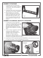
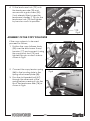
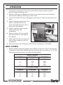
40”(1000mm) WOOD LATHE
WITH COPY FUNCTION
Model No CWL1000CF
Part No 6501670
OPERATING & MAINTENANCE
INSTRUCTIONS
GC0710
INTRODUCTION
Thank you for purchasing this CLARKE Wood Lathe.
Before attempting to operate the machine, it is essential that you read this
manual thoroughly and carefully follow all instructions given. In doing so you
will ensure the safety of yourself and that of others around you, and you can
also look forward to the product giving you long and satisfactory service.
GUARANTEE
This CLARKE product is guaranteed against faulty manufacture for a period of
12 months from the date of purchase. Please keep your receipt as proof of
purchase.
This guarantee is invalid if the product is found to have been abused or
tampered with in any way, or not used for the purpose for which it was
intended.
Faulty goods should be returned to their place of purchase, no product can
be returned to us without prior permission.
This guarantee does not effect your statutory rights.
ENVIRONMENTAL PROTECTION
Do not dispose of this product with general household waste. All tools,
accessories and packaging should be sorted, taken to a recycling
centre and disposed of according to the laws governing Waste
Electrical and Electronic Equipment.
PARTS & SERVICING
For parts & servicing, please contact your nearest dealer, or
CLARKE International, on one of the following numbers.
PARTS & SERVICE TEL: 020 8988 7400
PARTS & SERVICE FAX: 020 8558 3622
or e-mail as follows:
PARTS: [email protected]
SERVICE: [email protected]
2
CONTENTS
Introduction ............................................................................................ 2
Guarantee .............................................................................................. 2
Environmental Protection ...................................................................... 2
Parts & Service Contacts ....................................................................... 2
General Safety Rules ............................................................................. 4
Electrical Connections .......................................................................... 7
Main Components ................................................................................. 8
Unpacking & Assembly ......................................................................... 9
Operation ............................................................................................. 13
Maintenance ........................................................................................ 15
Troubleshooting .................................................................................... 16
Technical Specification ....................................................................... 17
Parts List and Diagrams ....................................................................... 18
Accessories .......................................................................................... 22
Declaration of Conformity .................................................................. 23
SAFETY SYMBOLS
The following safety symbols are displayed on the machine.
Wear dust protection
Wear eye protection
Read instructions before use
3
GENERAL SAFETY RULES
Important Note: Although the operation manual contains extensive instruction
on safe working with power tools, every power tool involves a certain residual
risk which cannot be completely excluded. Power tools must therefore
always be operated with caution.
WORK AREA SAFETY
1. Keep work area clean and well lit. Cluttered or dark areas invite
accidents.
2. Do not operate power tools in explosive atmospheres, such as In the
presence of flammable liquids, gases or dust. Power tools create sparks
which may Ignite the dust or fumes.
3. Keep children and bystanders away while operating a power tool.
Distractions can cause you to lose control.
ELECTRICAL SAFETY
1. Power tool plugs must match the outlet. Never modify the plug in any
way. Do not use any adapter plugs with earthed (grounded) power tools.
Unmodified plugs and matching outlets will reduce risk of electric shock.
2. Avoid body contact with earthed or grounded surfaces, such as pipes,
radiators, ranges and refrigerators. There is an increased risk of electric
shock if your body is earthed or grounded.
3. Do not expose power tools to rain or wet conditions. Water entering a
power tool will increase the risk of electric shock.
4. Do not abuse the cable. Never use the cable for pulling or unplugging the
power tool. Keep cable away from heat, oil, sharp edges or moving parts.
Damaged or entangled cables increase the risk of electric shock.
5. If operating a power tool in a damp location is unavoidable, use a
residual current device (RCD) protected supply. Use of an RCD reduces
the risk of electric shock.
PERSONAL SAFETY
1. Stay alert, watch what you are doing and use common sense when
operating a power tool. Do not use a power tool while you are tired or
under the influence of drugs, alcohol or medication. A moment of
inattention while operating power tools may result in serious personal
injury.
2. Use personal protective equipment. Always wear eye protection.
Protective equipment such as dust mask or non-skid safety shoes used in
appropriate conditions will reduce personal injuries.
3. Prevent unintentional starting. Ensure the switch is in the off-position
4
before connecting to power source and/or battery pack, picking up or
carrying the tool.
4. Remove any adjusting key or wrench before turning the power tool on. A
wrench or a key left attached to a rotating part of the power tool may
result in personal injury.
5. Do not overreach. Keep proper footing and balance at all times. This
enables better control of the power tool in unexpected situations.
6. Dress properly. Do not wear loose clothing or jewellery. Keep your hair,
clothing and gloves away from moving parts. Loose clothes, jewellery or
long hair can be caught in moving parts.
7. If devices are provided for the connection of dust extraction and
collection facilities, ensure these are connected and properly used. Use of
dust collection can reduce dust-related hazards.
POWER TOOL USE AND CARE
1. Do not force the power tool. Use the correct power tool for your
application. The correct power tool will do the job better and safer at the
rate for which it was designed.
2. Do not use the power tool if the switch does not turn it on and off. Any
power tool that cannot be controlled with the switch Is dangerous and
must be repaired.
3. Disconnect the plug from the power source, changing accessories, or
storing power tools. Such preventive safety measures reduce the risk of
starting the power tool accidentally.
4. Store idle power tools out of the reach of children and do not allow
persons unfamiliar with the power tool or these instructions to operate the
power tool. Power tools are dangerous in the hands of untrained users.
5. Maintain power tools. Check for misalignment or binding of moving parts,
breakage of parts and any other condition that may affect the power
tool’s operation. If damaged, have the power tool repaired before use.
Many accidents are caused by poorly maintained power tools.
6. Keep cutting tools sharp and clean. Properly maintained cutting tools with
sharp cutting edges are less likely to bind and are easier to control.
7. Use the power tool, accessories and tool bits etc. In accordance with
these instructions, taking into account the working conditions and the
work to be performed. Use of the power tool for operations different from
those intended could result in a hazardous situation.
SERVICE
1. Have your power tool serviced by a qualified repair person using only
identical replacement parts. This will ensure that the safety of the power
tool is maintained.
5
ADDITIONAL SAFETY RULES FOR WOODLATHES
1. IMPORTANT: You should not operate this machine unless you are
thoroughly familiar with woodlathes and turning techniques. If there is any
doubt whatsoever you should consult a qualified person.
2. ALWAYS store chisels safety when you have finished with the machine.
3. CAUTION: This machine is designed for use with wood lathe chisels only.
4. NEVER attempt to turn a workpiece unless a suitable support is used.
5. ALWAYS stop the lathe before removing workpieces, work supports or
swarf from the table.
6. ALWAYS be sure that the workpiece is securely locked in position.
7. ALWAYS keep hands and fingers away from the moving workpiece.
WARNING: DUST GENERATED FROM CERTAIN MATERIALS CAN BE
HAZARDOUS TO YOUR HEALTH. ALWAYS OPERATE THE LATHE IN A WELL
VENTILATED AREA. USE A DUST COLLECTION SYSTEM WHENEVER
POSSIBLE.
6
ELECTRICAL CONNECTIONS
WARNING! Read these electrical safety instructions thoroughly
before connecting the product to the mains supply.
Before switching the product on, make sure that the voltage of your electricity supply is the same as that indicated on the rating plate. This product is
designed to operate on 230VAC 50Hz. Connecting it to any other power
source may cause damage.
This product may be fitted with a non-rewireable plug. If it is necessary to
change the fuse in the plug, the fuse cover must be refitted. If the fuse cover
becomes lost or damaged, the plug must not be used until a suitable replacement is obtained.
If the plug has to be changed because it is not suitable for your socket, or
due to damage, it should be cut off and a replacement fitted, following the
wiring instructions shown below. The old plug must be disposed of safely, as
insertion into a mains socket could cause an electrical hazard.
WARNING! The wires in the power cable of this product are
coloured in accordance with the following code:
Blue = Neutral
Brown = Live
Yellow and Green = Earth
If the colours of the wires in the power cable of this product do not correspond with the terminal markings of your plug, proceed as follows.
•
The wire which is coloured Blue must be connected to the terminal which
is marked N or coloured Black.
•
The wire which is coloured Brown must be connected to the terminal
which is marked L or coloured Red.
•
The wire which is coloured Yellow and Green must be connected to the
terminal which is marked E or
or coloured Green.
Plug must be BS1363/A approved
Earth
(Green and Yellow)
Always fit a 13 Amp fuse.
Neutral
(Blue)
Live
(Brown)
Ensure that the outer sheath of the cable is firmly held by the clamp
We strongly recommend that this machine is connected to the mains supply
via a Residual Current Device (RCD).
If in doubt, consult a qualified electrician. DO NOT attempt repairs yourself.
7
MAIN COMPONENTS
A
A
ON/OFF Switch
J
Tail-stock Body
B
Speed Control
K
Tail-stock Advancing Handle
C
Headstock Centre Spur
L
Tool Rest Support
D
Tool Rest
M
Faceplate
E
Tool Rest Locking Lever
N
Open Wrench
F
Tool Holder
O
T-Spanner
G
Copy Tension Adjuster
P
Drift Rod
H
Copy Follower
Q
Cutting Tool(s)
I
Tail-stock Spur Assembly
R
Leadscrew Handles
B
C
L
Q
E
M
N
D
O
F
P
8
R
G
H
I
J
K
UNPACKING & ASSEMBLY
When unpacking, check for damage or omissions etc. Any found should be
reported to your CLARKE dealer where the lathe was originally purchased. Do
not discard the packaging until the lathe is assembled.
WARNING: DUE TO THE WEIGHT OF THE LATHE BED ASSEMBLY, IT IS
ESSENTIAL THAT TWO PEOPLE PERFORM THE UNPACKING, ASSEMBLY
AND POSITIONING.
The numbers in the following assembly instructions refer to the parts lists and
diagrams on pages 18-22.
The following items are supplied loose:
1 x Lathe c/w Tailstock & Tool Carrier
1 x Open Wrench
1 x Tool Rest
1 x Eye Shield Assembly
1 x Tool Rest Holder
1 x 10mm T-Wrench
1 x Face Plate
2 x Hex Keys (S3 & S4)
1 x Headstock Centre Spur
1 x Drift Rod
1 x Tailstock Spur Assembly
2 x Cutting Tools
1 x Copy Follower Assembly
3 x Wood Chisels
1 x Tool Holder Locking Handle
1 x Fixings Pack
3 x Leadscrew Handles
2 x Stand Front Legs
2 x Stand Rear Legs
2 x Stand Long Supports
2 x Stand Short Supports
2 x Stand Top Plates
1 x Stand Shelf Plate
1 x Instruction Manual (this document)
9
ASSEMBLY OF THE STAND
1. Assemble the front & rear legs,
supports and top plates using the
coachbolts, nuts and washers as
shown in Fig 1.
2. Assemble the stand loosely before
tightening all the fixings together.
3. With the help of an assistant,
position the lathe over the top
plates and align the holes in the
lathe bed with the holes in the
stand top plate. Secure with the
bolts supplied and tighten them
evenly.
Fig 1
ASSEMBLY OF FACEPLATE, TAILSTOCK & LEADSCREW
1. If faceplate turning is required,
screw the faceplate (24) onto the
headstock spindle (42) while using
the open wrench provided to
prevent the spindle from turning.
Tighten the faceplate as shown in
Fig 2.
2. If spur turning is required, insert the
headstock spur (25) into the
tapered hole in the headstock
spindle as shown in Fig 3a.
Fig 2
The spur can later easily be
removed by driving it away from the
headstock using the drift rod provided.
3. Insert the tail-stock spindle assembly (43/44/45) into the tail-stock as shown
in Fig 3b, the taper of the shaft gripping it in place.
Fig 3a
Fig 3b
10
4. Fit the leadscrew hub (79) onto
the leadscrew axle (78) and
secure with a grub-screw (50).
If not already fitted, screw the
leadscrew handles (113) into the
leadscrew hub (79) and tighten
by hand as much as possible.
Fig 4
ASSEMBLY OF THE COPY FOLLOWER
If the copy system is to be used
proceed as follows;
Fig 5
1. Position the copy follower body
(53) over the lead screw 3-way
trunnion (77) and connect it using
the copy pivot stud (73) and
tighten the nuts on each side as
shown in Fig 5.
2. Connect the copy tension spring
(68) to the locating hole in the
spring attachment plate (55).
Fig 6
3. Pass the slot-headed bolt (67)
through the other end of the
spring before screwing it into the
tip of the leadscrew axle (78) as
shown in Fig 6.
11
ASSEMBLING THE COPY TOOL
1. Install the copy toolholder rack
(64) into the hole in the copy
follower body (53) and drive it
through using the handwheel (1)
and the pinion gear (71) inside
the copy follower body.
Fig 7
2. Insert your chosen cutting tool
into the tool holder and tighten
the retaining bolt (118) using the
T- wrench as shown in Fig 7.
3. Advance the tool to the workpiece and
secure with the locking handle (59). The
tool tip should be at the same
height as the centre axis of the lathe.
Fig 8
4. Fit the eyeshield (115) to the copy follower
body using the socket-headed bolt (37) as
shown in Fig 8.
ASSEMBLING THE HAND CHISEL REST
If the copy system is not being used, the
standard tool rest for hand chisels can be
used as follows:
1. Set the chisel rest holder (101) on the lathe
bed and secure in position with the
securing plate (108) and the bolt/washer
(94/95) as shown in Fig 9.
2. Position the working edge of
the rest (100) level with the
centre axis of the lathe and
secure with the locking lever.
Fig 9
3. Position the rest level slightly
above the lathe centreline
and approx 3mm from the
workpiece and tighten the
locking handle (59) to secure.
The rest can be used parallel
with the workpiece or at 90
degrees for faceplate turning.
12
OPERATION
1. Ensure the cutting tool, tool rests and tailstock are securely locked in
position before starting work.
2. Always rotate the workpiece by hand and check it does not strike the
tool/tool rest before switching on the motor.
3. To turn the lathe ON, press the green push-button. Press the red button to
stop.
4. Avoid turning timber which has
splits or substantial knots or
voids and take special care if
these are discovered.
Fig 10
5. Always use the lowest speed
when starting a new
workpiece.
6. When turning, always roughly
turn the work to a cylinder at
low speed.
7. Take care that the turning tools
do not bite suddenly into the
workpiece.
8. Always position the toolrest just above the centreline of the lathe.
SPEED CONTROL
1. Set the speed using the speed control lever as shown in Fig 10. Always set
the lever to the lowest setting before switching the machine on or off. The
following settings serve as an approximate guide.
SPINDLE TURNING
SQUARE
ROUGHING
FINISHING
1"
1700
2200
2"
1200
2200
3"
700
2200
600
2200
4"
FACE PLATE TURNING
DIAMETER
ROUGHING
FINISHING
6"
1700
2200
8"
700
2200
9"
600
2200
13
COPY TURNING
1. Take the template object which
is to be copied and mark
diagonal lines on each end in
order to show the centre point
before installing it in the copy
stock position. Pierce the
template with the copy spindle
spur (8) and then tighten both
ends equally to hold the
template as shown in Fig 11.
2. Set the new workpiece in the
lathe by marking the centre
point as above and securing in
position between the head and
tailstock as shown in Fig 12.
Fig 11
Fig 12
3. Begin turning by roughing off the
workpiece until it is cylindrical and
ready for fine turning.
4. Check that the copy follower is
resting on the template object
and will follow the outline profile
as the assembly is moved along
as shown in Fig 13.
5. Set the tool post such that the
cutting tool is just level with the
axis of the lathe and workpiece
and begin turning progressively
from one end, advancing the tool
steadily. Take small cuts to assess
the progress and check that the
copy follower runs smoothly.
6. Progress slowly to ensure the copy
follower roller/pin remains in
contact with the template object
at all times. Take care that the
follower does not bounce on
sudden shape changes.
Fig 13
Different tools may be used according to the desired shape of the
workpiece; e.g, round-nosed, square-nosed, spear point, etc. These may
need changing during the operation.
14
MAINTENANCE
It is essential that the machine is properly maintained. Always inspect before
use. Any damage should be repaired and faults rectified. The machine
requires very little maintenance other than the following guidelines.
IMPORTANT - Disconnect from mains power before cleaning.
1. Vacuum clean any dust or shavings that accumulate in or on the motor.
2. Check all cables periodically for security, and that they are in good
condition and not cracked.
3. Check tightness of mounting bolts.
4. Check drive belt for wear and replace if frayed or otherwise damaged.
5. Periodically lubricate the tail-stock, copy stock and tool carrier screw
threads with engine oil such as SAE30 grade if they become stiff to use.
6. Lightly lubricate the tail-stock and tool-post locking handles with oil if they
become difficult to use.
• The ball bearings in the headstock and tail-stock spindles and in the copy
live roller pin are greased and permanently sealed at the factory and
require no further lubrication.
REPLACING THE BELT
1. Undo the retaining screws and
remove the belt guard.
2. By pushing the speed control
lever, expand the two halves
of the driven pulley (31)
allowing the belt to adopt its
smallest diameter at this end.
3. Rotate the motor pulley (18/
19) to dismount the drive belt
from it and then lift it off the
driven pulley.
4. Replacement is a reverse of
Fig 14
the removal procedure. A
broad-bladed screwdriver or
similar will be useful to prize the two halves of the motor pulley apart
against the pressure of the spring (17). Ensure the left & right halves of the
drive pulley spring back to grip the belt and that the belt is in tension.
In case of problems refer to TROUBLESHOOTING on page 16. If you are unable
to rectify any faults, please contact your local dealer or Clarke International
Service Department on 0208 988 7400 for assistance.
15
TROUBLESHOOTING
PROBLEM
Motor will not run.
CAUSES
SUGGESTIONS
1. Defective/broken switch.
Replace or return to your
Clarke dealer for repair.
2. Damaged power cable.
Replace cable or return to your
Clarke dealer for repair.
3. Open circuit, loose
connections or burned
out motor.
Return to your Clarke dealer for
repair. Attempting to repair the
motor may be hazardous unless
carried out by a qualified
technician.
4. Blown fuse or circuit breaker Replace fuse or re-set circuit
breaker. Turn off other
machines on the same circuit.
5. Low voltage
Motor will not start 1. Short circuit in motor or
and fuses or circuit
power cable.
breaker trip out.
2. Incorrect fuses or circuit
breakers.
Motor fails to
1. Overloaded circuit.
reach full power.
2. Unsuitable extension cable.
Motor stalls.
Noisy operation
Check the power supply for
correct voltage. Use another
circuit or have a qualified
electrician upgrade the power
supply.
Return to your Clarke dealer for
repair.
Replace with correct fuse or
circuit breaker for the circuit.
Turn off other machines & retry.
1. Short circuit in motor.
Replace with correct size
extension cable (rated at
<0.75mm2 section).
Return to your Clarke dealer for
repair. Attempting to repairing
the motor may be hazardous
unless carried out by a qualified
technician.
2. Incorrect fuses or circuit
breakers.
Replace with correct fuse or
circuit breaker for the circuit.
3. Overloaded circuit.
Turn off other machines & retry.
4. Low voltage.
Check the power supply for
correct voltage. Use another
circuit or have a qualified
electrician upgrade the service.
Adjust belt tension. See
"Replacing the Belt" section on
page 15.
1. Incorrect belt tension.
2. Worn bearings.
Tailstock loose on
bed
Locking handle not tight.
Overhaul or return to your
Clarke dealer for repair.
T ighten locking handle
Wood burns at
tailstock end
Tailstock set too tight. Lack of
lubrication.
Ease off tailstock adjustment
and lubricate tailstock spur.
16
TECHNICAL SPECIFICATION
Feature
Specification
Weight
69 kg
Dimensions (L x W x H)
1440 x 455 x 1180 mm
Speed
600 - 2200 rpm (variable)
Distance between centres
1000 mm
Height of centreline from base frame
173 mm
Turning Capacity
350 mm
Headstock Thread
3/4" UNF
Headstock Taper
MT1
Tailstock Taper
MT2
Motor Operating Voltage/Frequency
230V 50Hz
Rated Input Wattage
550 W
Motor Output
370 W
Sound Pressure Level LpA
No load 72.9 / Loaded 79 dB(A)
Measured Sound Power Level LwA
No load 85.9 / Loaded 92 dB(A)
Uncertainty K
3.0 dB(A)
Please note that the details and specifications contained herein, are correct at the
time of going to print. However, CLARKE International reserve the right to change
specifications at any time without prior notice.
17
PARTS LIST
No
1
Description
No
Description
Hand Wheel
32
Speed Shift Lever
2
Grub Screw M6 x 10
33
Coil Spring
3
Support Arm
34
Nut M8
4
Washer 8 mm diameter
35
Bolt M8 x 25 mm
5
Machine Screw M6 x 8
36
Speed Control Shaft
6
Folded Plate
37
Socket head Bolt M8 x 20
7
Movable Plate
38
Circlip
8
Copy Spindle M18
39
Bearing 80205
9
Bolt M6 x 8
40
Circlip 52 mm diameter
10
Hinge
41
Spindle Key
11 S/t Screw M4 x 8
42
Headstock Spindle
12
Spindle Cover Plate
43
Tailstock Spur
13
Grub Screw M5 x 8 mm
44
Bearing 80201
14
Power Cable
45
Taper Shank
15
Circlip 22mm
46
Tailstock Body
16
Penny Washer
47
Tailstock Spindle
17
Coil Spring
48
Locking Nut M18
18
Motor Pulley (Left)
49
Tailstock Handwheel
19
Motor Pulley (Right)
50
Grubscrew M8 x 8
20
Washer 5 mm dia
51
Bearing 80025
21
Parallel Key
52
Living Roller Arm Pin
22
Motor
53
Copy Follower Body
23
Headstock Body
54
Copy Tension Screw
24
Face Plate
55
Spring Attachment Plate
25
Spur Centre
56
Grubscrew M6 x 5 mm
26
Circlip 24 dia
57
Tool Carrier Pinion
27
Pulley Spindle (right)
58
Cover Tab
28
Drive Belt 560 mm circumferance
59
Locking Handle Arm
29
Pulley Spindle (left)
60
Wear Block
30
Circlip 55 dia
61
Screwed Shank
31
Bearing B0106
62
Screw
18
PARTS DIAGRAM
When requesting spare parts, please quote the reference DDCWL1000
followed by the number (1-118) on the following parts lists.
19
PARTS LIST
No
Description
No
Description
63
Bolt M6 x 25 mm
94
Bolt M16x35
64
Copy Toolholder Rack
95
Washer 16 dia
65
Copy Toolholder Pinion
96
Lathe Bed
66
Circlip 8 mm dia
97
Washer 10 dia
67
Slot Headed Bolt
98
Bolt M10 x18
Stand Top Plate
68
Copy Tension Spring
99
69
Circlip 6 mm dia
100 Chisel Rest
70
Bearing 80200
101 Chisel Rest Holder
71
Leadscrew Pinion
102 Stand Front (right)
72
Nut M12
103 Anchor Plate
73
Copy Pivot Stud
104 Stand Long Support
74
Leadscrew Bearing Rest
105 Stand Front (left)
75
Bearing 80201
106 Stand Cross Support
76
Leadscrew Guide Rack
107 Coachbolt M8x12
77
3-way Trunnion
108 Securing Plate
78
Leadscrew Axle
109 Washer 8 mm dia
79
Leadscrew Hub
110 Stand Base Plate
80
Nut M10
111 Cable Gland M16x1,5
81
Knob
112 Belt Guard
82
Cover Retaining Screw
113 Leadscrew Handle
83
ON/OFF Switch
114 Bolt M8 x 16
84
Screw M8 x 12
115 Eye Shield
85
Speed Control Spindle
116 Capacitor 10uF
86
Speed Label
117 Capacitor Cover
87
Circlip
118 Tool Retaining Bolt
88
Speed Control Cam
n/a Open Spanner
89
C/sunk Screw M4x20
n/a Drift Rod
90
Pin
n/a Hexagonal Key S3
91
Speed Control Lever
n/a Hexagonal Key S4
92
Washer
n/a T-Wrench
93
Bolt M8x20
n/a User Manual
20
PARTS DIAGRAM
When requesting spare parts, please quote the reference DDCWL1000
followed by the number (1-118) on the accompanying parts lists.
21
PARTS DIAGRAM
When requesting spare parts, please quote the reference DDCWL1000
followed by the number (1-118) on the following parts lists.
ACCESSORIES
The following range of accessories is also available from your Clarke dealer:
8-Piece Chisel Set
Part No: 6500649
4-Jaw Independent Lathe Chuck
Part No: 6500645
1/2” Cap. Tailstock Chuck
Part No: 6500643
22
DECLARATION OF CONFORMITY
23