1
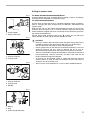
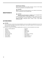
ENGLISH
Rotary Hammer
MODEL HR2450
MODEL HR2450F
MODEL HR2450X
MODEL HR2450T
MODEL HR2450FT
MODEL HR2451
003571
DOUBLE
INSULATION
I N S T R U C T I O N
M A N U A L
WARNING:
For your personal safety, READ and UNDERSTAND before using.
SAVE THESE INSTRUCTIONS FOR FUTURE REFERENCE.
SPECIFICATIONS
Model
HR2450/HR2450X/HR2450F/HR2451
HR2450T/HR2450FT
Tungsten-carbide tipped bit
24 mm
Core bit
54 mm
Diamond core bit
65 mm
Concrete
Capacities
Steel
13 mm
Wood
32 mm
No load speed (min-1)
0 - 1,100
Blows per minute
0 - 4,500
Overall length
360 mm
Net weight
2.4 kg
Safety class
384 mm
2.6 kg
/II
• Due to our continuing programme of research and development, the specifications herein are subject to change
without notice.
• Note: Specifications may differ from country to country.
SYMBOLS
END201-1
The following show the symbols used for the tool. Be
sure that you understand their meaning before use.
...................Read instruction manual.
...................DOUBLE INSULATION
Intended use
The tool is intended for hammer drilling and drilling in
brick, concrete and stone as well as for chiselling work.
It is also suitable for drilling without impact in wood,
metal, ceramic and plastic.
Power supply
The tool should be connected only to a power supply of
the same voltage as indicated on the nameplate, and
can only be operated on single-phase AC supply. They
are double-insulated in accordance with European
Standard and can, therefore, also be used from sockets
without earth wire.
2
For European countries only
Noise and Vibration
The typical A-weighted noise levels are
sound pressure level: 89 dB (A)
sound power level: 102 dB (A)
– Wear ear protection. –
The typical weighted root mean square acceleration
value is 9.0 m/s2.
EC-DECLARATION OF CONFORMITY
We declare under our sole responsibility that this product
is in compliance with the following standards of standardized documents, HD400, EN50144, EN55014,
EN61000 in accordance with Council Directives, 73/23/
EEC, 89/336/EEC, 98/37/EC.
Yasuhiko Kanzaki CE 2002
Director
MAKITA INTERNATIONAL EUROPE LTD.
Michigan Drive, Tongwell, Milton Keynes, Bucks MK15
8JD, ENGLAND
SAFETY INSTRUCTIONS
ENA001-2
WARNING:
When using electric tools, basic safety precautions, including the following,
should always be followed to reduce the risk of fire, electric shock and
personal injury. Read all these instructions before operating this product
and save these instructions.
For safe operations:
1.
Keep work area clean.
Cluttered areas and benches invite injuries.
2.
Consider work area environment.
Do not expose power tools to rain. Do not use
power tools in damp or wet locations. Keep work
area well lit. Do not use power tools where there is
risk to cause fire or explosion.
Guard against electric shock.
Avoid body contact with earthed or grounded surfaces (e.g. pipes, radiators, ranges, refrigerators).
Keep children away.
Do not let visitors touch the tool or extension cord.
All visitors should be kept away from work area.
Store idle tools.
When not in use, tools should be stored in a dry,
high or locked up place, out of reach of children.
Do not force the tool.
It will do the job better and safer at the rate for which
it was intended.
Use the right tool.
Do not force small tools or attachments to do the job
of a heavy duty tool. Do not use tools for purposes
not intended; for example, do not use circular saws
to cut tree limbs or logs.
Dress properly.
Do not wear loose clothing or jewellery, they can be
caught in moving parts. Rubber gloves and non-skid
footwear are recommended when working outdoors. Wear protecting hair covering to contain long
hair.
Use safety glasses and hearing protection.
Also use face or dust mask if the cutting operation is
dusty.
Connect dust extraction equipment.
If devices are provided for the connection of dust
extraction and collection facilities ensure these are
connected and properly used.
Do not abuse the cord.
Never carry the tool by the cord or yank it to disconnect it from the socket. Keep the cord away from
heat, oil and sharp edges.
Secure work.
Use clamps or a vice to hold the work. It is safer
than using your hand and it frees both hands to
operate the tool.
Do not overreach.
Keep proper footing and balance at all times.
Maintain tools with care.
Keep cutting tools sharp and clean for better and
safer performance. Follow instructions for lubrica-
3.
4.
5.
6.
7.
8.
9.
10.
11.
12.
13.
14.
15.
16.
17.
18.
19.
20.
21.
22.
tion and changing accessories. Inspect tool cord
periodically and if damaged have it repaired by an
authorized service facility. Inspect extension cords
periodically and replace, if damaged. Keep handles
dry, clean and free from oil and grease.
Disconnect tools.
When not in use, before servicing and when changing accessories such as blades, bits and cutters.
Remove adjusting keys and wrenches.
Form the habit of checking to see that keys and
adjusting wrenches are removed from the tool
before turning it on.
Avoid unintentional starting.
Do not carry a plugged-in tool with a finger on the
switch. Ensure switch is off when plugging in.
Use outdoor extension leads.
When tool is used outdoors, use only extension
cords intended for outdoor use.
Stay alert.
Watch what you are doing. Use common sense. Do
not operate tool when you are tired.
Check damaged parts.
Before further use of the tool, a guard or other part
that is damaged should be carefully checked to
determine that it will operate properly and perform
its intended function. Check for alignment of moving
parts, free running of moving parts, breakage of
parts, mounting and any other conditions that may
affect its operation. A guard or other part that is
damaged should be properly repaired or replaced
by an authorized service center unless otherwise
indicated in this instruction manual. Have defective
switches replaced by an authorized service facility.
Do not use the tool if the switch does not turn it on
and off.
Warning.
The use of any accessory or attachment, other than
those recommended in this instruction manual or
the catalog, may present a risk of personal injury.
Have your tool repaired by a qualified person.
This electric tool is in accordance with the relevant
safety requirements. Repairs should only be carried
out by qualified persons using original spare parts,
otherwise this may result in considerable danger to
the user.
3
ADDITIONAL SAFETY RULES FOR TOOL
1.
Hold tools by insulated gripping surfaces when
performing an operation where the cutting tool
may contact hidden wiring or its own cord. Contact with a “live” wire will make exposed metal parts
of the tool “live” and shock the operator.
2.
Wear ear protectors when using the tool for
extended periods. Prolonged exposure to high
intensity noise can cause hearing loss.
Wear a hard hat (safety helmet), safety glasses
and/or face shield. It is also highly recommended that you wear a dust mask and thickly
padded gloves.
Be sure the bit is secured in place before operation.
Under normal operation, the tool is designed to
produce vibration. The screws can come loose
easily, causing a breakdown or accident. Check
tightness of screws carefully before operation.
3.
4.
5.
6.
In cold weather or when the tool has not been
used for a long time, let the tool warm up for a
while by operating it under no load. This will
loosen up the lubrication. Without proper warmup, hammering operation is difficult.
7. Always be sure you have a firm footing.
Be sure no one is below when using the tool in
high locations.
8. Hold the tool firmly with both hands.
9. Keep hands away from moving parts.
10. Do not leave the tool running. Operate the tool
only when hand-held.
11. Do not point the tool at any one in the area when
operating. The bit could fly out and injure someone seriously.
12. Do not touch the bit or parts close to the bit
immediately after operation; they may be
extremely hot and could burn your skin.
SAVE THESE INSTRUCTIONS
4
ENB010-1
FUNCTIONAL
DESCRIPTION
•
001292
CAUTION:
Always be sure that the tool is switched off and unplugged before
adjusting or checking function on the tool.
Switch action
CAUTION:
Before plugging in the tool, always check to see that the switch trigger
actuates properly and returns to the “OFF” position when released.
To start the tool, simply pull the switch trigger. Tool speed is increased by
increasing pressure on the switch trigger. Release the switch trigger to stop.
For continuous operation, pull the switch trigger and then push in the lock button. To stop the tool from the locked position, pull the switch trigger fully, then
release it.
•
1
2
1. Switch trigger
2. Lock button
Lighting up the lamps
003572
For model HR2450F/HR2450FT
CAUTION:
• Do not look in the light or see the source of light directly.
To turn on the lamp, pull the trigger. Release the trigger to turn it off.
NOTE:
•
1
Use a dry cloth to wipe the dirt off the lens of lamp. Be careful not to
scratch the lens of lamp, or it may lower the illumination.
1. Lamp
001293
A
1
B
2
Reversing switch action
For Model HR2450,HR2450F,HR2450X,HR2450T and HR2450FT
This tool has a reversing switch to change the direction of rotation. Move the
reversing switch lever to the
position (A side) for clockwise rotation or the
position (B side) for counterclockwise rotation.
•
•
1. Switch trigger
2. Reversing switch lever
•
CAUTION:
Always check the direction of rotation before operation.
Use the reversing switch only after the tool comes to a complete stop.
Changing the direction of rotation before the tool stops may damage the
tool.
When you operate the tool in counterclockwise rotation, the switch
trigger is pulled only halfway and the tool runs at half speed. For
counterclockwise rotation, you cannot push in the lock button.
5
004415
1
2
3
Changing the quick change chuck for SDS-plus
For model HR2450T/HR2450FT
The quick change chuck for SDS-plus can be easily exchanged for the quick
change drill chuck.
Removing the quick change chuck for SDS-plus
CAUTION:
Before removing the quick change chuck for SDS-plus, always remove
the bit.
Grasp the change cover of the quick change chuck for SDS-plus and turn in
the direction of the arrow until the change cover line moves from the symbol
to the symbol to the <RHAM Unlock> symbol. Pull forcefully in the direction
of the arrow.
•
1. Quick change chuck for SDS-plus
2. Change cover line
3. Change cover
004416
1
2
3
Attaching the drill quick change drill chuck
Check the line of the quick change drill chuck shows the symbol. Grasp the
change cover of the quick change drill chuck and set the line to the symbol.
Place the quick change drill chuck on the spindle of the tool.
Grasp the change cover of the quick change drill chuck and turn the change
cover line to the symbol until a click can clearly be heard.
4
1.
2.
3.
4.
Quick change drill chuck
Change cover line
Change cover
Spindle
Selecting the action mode
003573
1
2
Rotation with hammering
For drilling in concrete, masonry, etc., depress the lock button and rotate the
action mode changing knob to the
symbol. Use a tungsten-carbide tipped
bit.
3
1. Rotation with hammering
2. Lock button
3. Action mode changing knob
003575
1
1. Rotation only
6
Rotation only
For drilling in wood, metal or plastic materials, depress the lock button and
rotate the action mode changing knob to the
symbol. Use a twist drill bit or
wood bit.
003574
1
Hammering only
For chipping, scaling or demolition operations, depress the lock button and
rotate the action mode changing knob to the
symbol. Use a bull point, cold
chisel, scaling chisel, etc.
•
•
1. Hammering only
CAUTION:
Do not rotate the action mode changing knob when the tool is running
under load. The tool will be damaged.
To avoid rapid wear on the mode change mechanism, be sure that the
action mode changing knob is always positively located in one of the
three action mode positions.
Torque limiter
The torque limiter will actuate when a certain torque level is reached. The
motor will disengage from the output shaft. When this happens, the bit will stop
turning.
•
•
ASSEMBLY
•
001295
4
1
2
3
1.
2.
3.
4.
5.
6.
6
CAUTION:
As soon as the torque limiter actuates, switch off the tool immediately.
This will help prevent premature wear of the tool.
Hole saws cannot be used with this tool. They tend to pinch or catch
easily in the hole. This will cause the torque limiter to actuate too
frequently.
CAUTION:
Always be sure that the tool is switched off and unplugged before
carrying out any work on the tool.
Side grip (auxiliary handle)
5
CAUTION:
• Always use the side grip to ensure operating safety.
Install the side grip so that the teeth on the grip fit in between the protrusions
on the tool barrel. Then tighten the grip by turning clockwise at the desired
position. It may be swung 360° so as to be secured at any position.
Grip base
Side grip
Loosen
Teeth
Protrusion
Tighten
Bit grease
Coat the bit shank head beforehand with a small amount of bit grease
(about 0.5 - 1 g).
This chuck lubrication assures smooth action and longer service life.
7
001296
Installing or removing the bit
Clean the bit shank and apply bit grease before installing the bit.
1
2
1. Bit shank
2. Bit grease
001297
Insert the bit into the tool. Turn the bit and push it in until it engages.
After installing, always make sure that the bit is securely held in place by trying
to pull it out.
001298
To remove the bit, pull the chuck cover down all the way and pull the bit out.
003576
Bit angle (when chipping, scaling or demolishing)
1
2
1. Bit
2. Chuck cover
1
2
1. Bit
2. Chuck cover
The bit can be secured at the desired angle. To change the bit angle, depress
the lock button and rotate the action mode changing knob to the O symbol.
Turn the bit to the desired angle.
1
1. Action mode changing knob
2. Lock button
8
2
003577
Depress the lock button and rotate the action mode changing knob to the
symbol. Then make sure that the bit is securely held in place by turning it
slightly.
001299
Depth gauge
The depth gauge is convenient for drilling holes of uniform depth. Loosen the
side grip and insert the depth gauge into the hole in the side grip. Adjust the
depth gauge to the desired depth and tighten the side grip.
1
NOTE:
•
The depth gauge cannot be used at the position where the depth gauge
strikes against the gear housing.
1. Depth gauge
001300
1
Dust cup
Use the dust cup to prevent dust from falling over the tool and on yourself
when performing overhead drilling operations. Attach the dust cup to the bit as
shown in the figure. The size of bits which the dust cup can be attached to is
as follows.
C00022
Bit diameter
Dust cup 5
6 mm - 14.5 mm
Dust cup 9
12 mm - 16 mm
1. Dust cup
OPERATION
003579
Hammer drilling operation
Set the action mode changing knob to the
symbol.
Position the bit at the desired location for the hole, then pull the switch trigger.
Do not force the tool. Light pressure gives best results. Keep the tool in position and prevent it from slipping away from the hole.
Do not apply more pressure when the hole becomes clogged with chips or
particles. Instead, run the tool at an idle, then remove the bit partially from the
hole. By repeating this several times, the hole will be cleaned out and normal
drilling may be resumed.
•
CAUTION:
There is a tremendous and sudden twisting force exerted on the tool/bit
at the time of hole break-through, when the hole becomes clogged with
chips and particles, or when striking reinforcing rods embedded in the
concrete. Always use the side grip (auxiliary handle) and firmly hold the
tool by both side grip and switch handle during operations. Failure to do
so may result in the loss of control of the tool and potentially severe
injury.
9
002449
Blow-out bulb (optional accessory)
After drilling the hole, use the blow-out bulb to clean the dust out of the hole.
1
1. Blow-out bulb
003580
Chipping/Scaling/Demolition
Set the action mode changing knob to the
symbol.
Hold the tool firmly with both hands. Turn the tool on and apply slight pressure
on the tool so that the tool will not bounce around, uncontrolled. Pressing very
hard on the tool will not increase the efficiency.
10
Drilling in wood or metal
004223
1
2
1. Chuck adapter
2. Keyless drill chuck
For Model HR2450/HR2450F/HR2450X/HR2451
Use the optional drill chuck assembly. When installing it, refer to “Installing or
removing the bit” described on the previous page.
For model HR2450T/HR2450FT
Use the quick change drill chuck as standard equipment. When installing it,
refer to “changing the quick change chuck for SDS-plus” described on the
previous page.
Hold the ring and turn the sleeve counterclockwise to open the chuck jaws.
Place the bit in the chuck as far as it will go. Hold the ring firmly and turn the
sleeve clockwise to tighten the chuck. To remove the bit, hold the ring and turn
the sleeve counterclockwise.
Set the action mode changing knob to the
symbol. You can drill up to
13mm diameter in metal and up to 32mm diameter in wood.
004415
1
2
3
•
•
•
1. Quick change chuck for SDS-plus
2. Change cover line
3. Change cover
004416
1
2
•
•
CAUTION:
Never use “rotation with hammering” when the quick change drill chuck is
installed on the tool. The quick change drill chuck may be damaged.
Also, the drill chuck will come off when reversing the tool.
Pressing excessively on the tool will not speed up the drilling. In fact, this
excessive pressure will only serve to damage the tip of your bit,
decrease the tool performance and shorten the service life of the tool.
There is a tremendous twisting force exerted on the tool/bit at the time of
hole breakthrough. Hold the tool firmly and exert care when the bit
begins to break through the workpiece.
A stuck bit can be removed simply by setting the reversing switch to
reverse rotation in order to back out. However, the tool may back out
abruptly if you do not hold it firmly.
Always secure small workpieces in a vise or similar hold-down device.
3
4
1.
2.
3.
4.
Quick change drill chuck
Change cover line
Change cover
Spindle
004224
1
2
3
1. Sleeve
2. Ring
3. Quick change drill chuck
11
Diamond core drilling
When performing diamond core drilling operations, always set the change
lever to the
position to use “rotation only” action.
CAUTION:
If performing diamond core drilling operations using “rotation with hammering”
action, the diamond core bit may be damaged.
MAINTENANCE
CAUTION:
Always be sure that the tool is switched off and unplugged before
attempting to perform inspection or maintenance.
To maintain product SAFETY and RELIABILITY, repairs, carbon brush inspection and replacement, any other maintenance or adjustment should be performed by Makita Authorized Service Centers, always using Makita
replacement parts.
•
ACCESSORIES
CAUTION:
These accessories or attachments are recommended for use with your Makita tool specified in this manual. The
use of any other accessories or attachments might present a risk of injury to persons. Only use accessory or
attachment for its stated purpose.
If you need any assistance for more details regarding these accessories, ask your local Makita service center.
•
•
•
•
•
•
•
•
•
•
12
SDS-Plus Carbide-tipped bits
Bull point
Cold chisel
Scaling chisel
Grooving chisel
Drill chuck assembly
Drill chuck S13
Chuck adapter
Chuck key S13
•
•
•
•
•
•
•
•
•
Bit grease
Side grip
Depth gauge
Blow-out bulb
Dust cup
Dust extractor attachment
Safety goggles
Plastic carrying case
Keyless drill chuck
Memo
13
Memo
14
Memo
15
Makita Corporation
884425D220