1
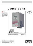
COMBIVERT
USA
F5-B Indexing
INDUSTRIAL MOTION CONTROL, LLC
Installation Guide & Operation Manual
FOR TECHNICAL SUPPORT PLEASE CALL
INDUSTRIAL MOTION CONTROL, LLC
AT
(847) 459-5200
Additional copies of manuals are available at
www.camcoindex.com
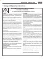
The icons below are used to draw draw attention to the reader.
They have the following meanings:
Danger!
Warning!
Caution!
Attention!
Observe at
all costs!
Information
Hint
Tip
Contents
Table of Contents
1. Safety and Operating Instructions ...........................................5
2. Product Description ..................................................................6
2.1 Application .................................................................................... ..6
2.2 Part Number Identification ............................................................ ..6
2.3 Technical Data .............................................................................. ..7
2.3.1 Technical Data 230V Class ............................................................... ..7
2.3.2 Technical Data 460V Class ............................................................... ..8
2.4 Dimensions and terminals ............................................................ ..9
2.4.1 A Housing .......................................................................................... ..9
2.4.2 B Housing ........................................................................................ ..10
2.4.3 D Housing ........................................................................................ ..11
3. Installation and Connection ................................................. ..12
3.1 Control Cabinet Installation ........................................................ ..12
3.2 Good EMC Installation Techniques ............................................ ..13
3.3 Connection of Power Circuit ....................................................... ..14
3.3.1 Wiring instructions ........................................................................... ..14
3.3.2 Terminal X1.A & Line Connection ................................................... ..15
3.3.3 Motor Connection ............................................................................ ..18
3.3.4 Motor Overload Protection .............................................................. ..19
3.3.5 Motor Terminal Connections ........................................................... ..19
3.3.6 IMC Motors ..................................................................................... ..20
3.3.7 EMI(CE) Filters ............................................................................... ..20
3.3.8 CAM Gear Box ............................................................................... ..21
3.4 Breaking Resistor ....................................................................... ..22
3.4.1 Explanation ...................................................................................... ..22
3.4.2 Options ............................................................................................ ..22
3.4.3 Connection ..................................................................................... ..23
3.4.4 Selection .......................................................................................... ..24
3.5 Control Circuit: F5-BASIC ......................................................... ..26
3
Contents
3.5.1 Terminal Strip Connections ............................................................. ..26
3.5.2 Connection of the control signals .................................................... ..26
3.5.3 Digital Inputs .................................................................................... ..27
3.5.4 Analog Inputs ................................................................................... ..27
3.5.5 Analog Output ................................................................................. ..27
3.5.6 Relay Outputs .................................................................................. ..27
3.5.7 Suggested wiring ............................................................................. ..28
3.5.8 Operation Explanation ..................................................................... ..29
3.5.9 Optional Speed Control Wiring ........................................................ ..31
3.5.10 F4si to F5Bi conversion ................................................................. ..31
3.5.11 Optional Jog Wiring ....................................................................... ..31
4. Operation of the inverter ........................................................32
4.1 Digital Operator .......................................................................... ..32
4.1.1 Keypad ............................................................................................ ..33
4.2 Parameter Summary .................................................................. ..34
4.3 Password Input ........................................................................... ..35
4.4 Operating Displays ..................................................................... ..35
4.5 Adjustment of the Drive .............................................................. ..36
4.6 The "Drive Mode" ....................................................................... ..46
4.6.1 Start / Stop Drive ............................................................................. ..46
4.6.2 Changing the Direction of Rotation ................................................. ..46
4.6.3 Speed setting .................................................................................. ..46
4.6.4 Leaving "Drive Mode" ..................................................................... ..46
5. Error Diagnosis .......................................................................47
6. Quick Reference ......................................................................51
7. Suggested Systems ............................................................. ..53
8. Accessories .............................................................................54
4
Important, please read
1. Safety and Operating Instructions
Safety and operating instructions for
AC motor controls
(in conformity with the low-voltage directive 73/23/EEC)
1. General
4. Installation
AC motor controls, depending on their degree of protection,
may have exposed live, un-insulated, and possibly also moving or rotating parts, as well as hot surfaces.
The installation and cooling of the unit shall be in accordance
with the specifications contained with in this document.
Removal of the protective covers, improper use, improper installation or operation, can be dangerous and result in serious
personal injury and or damage to property.
This document must be read in its entirety before attempting to
apply voltage to the KEB COMBIVERT F5.
All functions of, installation and commissioning as well as
maintenance are to be carried out by skilled or certified technical personnel (Observe IEC 364 or CENELEC HD 384 or DIN
VDE 0100 and IEC 664 or DIN/VDE 0110, NEC and all national and local codes and accident prevention rules!).
For the purposes of these basic safety instructions, ”skilled technical personnel“ means persons who are familiar with the installation, mounting, commissioning and operation of the product and have the qualifications needed for the performance of
their functions.
2. Intended use
AC motor controls are components designed for installation and
operation in electrical installations or machinery.
In case of installation in machinery, commissioning of the drive
converter (i.e. the starting of normal operation) is prohibited
until the machinery has been proved to conform to the provisions of the directive 89/392/EEC (Machinery Safety Directive
- MSD). Account is to be taken of EN 60204.
Commissioning (i.e. the starting of normal operation) is admissible only where conformity with the EMC directive (89/336/
EEC) has been established. The KEB COMBIVERT F5 motor
controls meet the requirements of the low-voltage directive 73/
23/EEC. They are subject to the harmonized standards of the
series DIN EN 50178/VDE 0160 in conjunction with EN 604391/ VDE 0660, part 500, and EN 60146/ VDE 0558.
The technical data as well as information concerning the supply conditions shall be taken from the name plate and from the
documentation and shall be strictly observed.
3. Transport, storage
The instructions for transport, storage and proper use shall be
complied with.
The climatic conditions shall be in conformity with EN 50178.
The unit shall be protected against excessive force or strain. In
particular, no components must be bent or isolating distances
altered in the course of transportation or handling. No contact
shall be made with electronic components and contacts.
Drive converters contain electrostatic sensitive components
which are can be damaged through improper use or handling.
Electric components must not be mechanically damaged or
destroyed (potential health risks).
5. Electrical connection
RISK OF ELECTRIC SHOCK! Always disconnect the supply
voltage before installing or servicing the KEB COMBIVERT F5
motor control! Wait five minutes for the before attempting to
change any connections as the internal DC bus must first discharge.
If it is necessary to work with the voltage supply turned on,
always comply with the applicable national accident prevention
rules (ex O.S.H.A.).
The electrical installation shall be carried out in accordance
with the relevant requirements (NEC and local codes). For further information, see documentation.
Instructions for installation in accordance with EMC requirements, like shielding, grounding, location of filters and wiring,
are included in the documentation. They must always be complied with. Motor controls bearing a CE marking do not preclude adherence to proper EMC installation requirements. Observance of the allowed values required by EMC law is the
responsibility of the designer or manufacturer of the installation or machine.
6. Operation
Installations which include motor controls shall be equipped
with additional control and protective devices in accordance
with the relevant applicable safety requirements. Changes to
the motor control by means of the operating software are admissible.
After disconnection of the motor control from the supply voltage, live parts and power terminals must not be touched because DC BUS capacitors may still be energized. Always follow the printed warnings on the unit.
During operation, all covers and doors shall be kept closed.
7. Maintenance and servicing
The manufacturer’s documentation shall be followed.
KEEP SAFETY INSTRUCTIONS IN A SAFE PLACE!
5
Product Description
2. Product Description
2.1 Application
The KEB COMBIVERT F5 series motor control is designed exclusively for the control and
regulation of induction motors. The operation of other electric devices and loads is prohibited and can lead to the destruction of the unit.
The F5 series motor control is a component which is intended for the installation in electric
systems or machines.
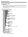
2.2 Part Number Identification
07.F5.B0A–PM00
Version
0: Standard
Interface type
0: none
Customer Specification
M: IMC Indexing Unit
Input identification
P: 230 VAC or 325 VDC
R: 460 VAC or 650 VDC
Housing type
A: A Housing
B: B Housing
D: D Housing
Accessory
0: None
1: GTR 7 1)
3: GTR7 1), integrated EMI filter
Control type
B: BASIC
Series F5
Inverter size
1)
2)
6
GTR 7:
PFC:
Braking transistor
Power Factor Correction
Product Description
2.3 Technical Data
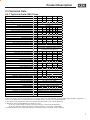
2.3.1 Technical Data 230V Class
Inverter Size
Recommended Motor Power
Housing size
5
[hp] 1/2
A
7
1
A
9
2
B
10
3
B
12
5
D
Input Ratings
Supply voltage
[V]
Supply voltage frequency [Hz]
Input phases
Rated input current
[A]
Recommended maximum input fuse
[A]
Recommended wire gauge1) [awg]
Output Ratings
Rated output power [kVA]
Rated motor power [kW]
Rated output current
[A]
Peak current (30 seconds)
[A]
Over current fault (E.OC) trip level
[A]
Overload curve (see annex)
Output voltage
[V]
Output frequency
[Hz]
180...260 ±0 (230 V rated voltage)
50 / 60 +/- 2
1
1 3 1 3
3
8.0
14 9.5 19 13
21
15
20 15 25 20
25
14
12 14 10 12
10
1
4.0
15
14
0.9
0.37
2.0
4.1
5.0
1.6
0.75
4.0
7.2
8.6
2.8
4.0
6.6
1.5
2.2
4.0
6.8
9.6
15.2
12.6
18.0
29.7
15.1
21.6
35.6
1
3 x 0...V input (3 x 0...255V)
Generally 0 to 1600Hz (limited by control
board and carrier frequency)
Rated switching frequency [kHz]
4
8
16
8
8
Maximum switching frequency [kHz]
8
8
16
16
16
4)
[W] 30
55
90
105
210
Power loss at rated operation
Stall current at 4kHz
[A] 2.3
4
7
10
16.5
Stall current at 8kHz
[A] 2.3
4
7
10
16.5
Stall current at 16kHz
[A]
–
–
7
8
10
Braking Circuit
47
33
27
Min. braking resistance 2) [Ohm]
68
56
33
Typ. braking resistance 2) [Ohm]
Max. braking current
[A]
9.5
12
15
Installation Information
30
330
Max. shielded motor cable length at 4 kHz 3) [ft] 30
30
330
Max. shielded motor cable length at 8 kHz 3) [ft] 30
3)
330
130
–
–
Max. shielded motor cable length at 16kHz [ft]
Tightening torque for terminal strip [in lb]
4.5
Environmental
Max. heat sink temperature TOH [°C]
90°C / 194°F
Storage temperature [°C]
-25...70 °C / -13…158°F
Operating temperature [°C]
-10...45 °C / 14…113°F
Housing design / protection
Chassis / IP20
Relative humidity
max. 95% without condensation
Approvals
Tested in accordance with…
EN 61800-3 /UL508C
Standards for emitted interference
EN 55011 Class B / EN 55022 Class A
Standards for noise immunity
IEC 1000-4-2 / -3 / -4 / -5/ -6
Climatic category
3K3 in accordance with EN 50178
1) The wire gauge is based on the maximum fuse rating, copper wire with minimum 75°C insulation rating, THHW or equivalent. If
branch circuit protection is selected based on rated input current, the wire size could be reduced.
2) This data is only valid for units with internal brake transistor GTR 7 (see "unit identification")
3) With units with integrated EMI filter the distance is less:
up to max. 5m line length and 4kHz operating frequency = Limit Value B (EN 55011)
up to max. 10m line length and 16kHz operating frequency = Limit Value A (EN 55022)
4) Rated operation means rated input voltage, rated output current, and rated carrier frequency.
7
Product Description
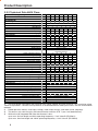
2.3.2 Technical Data 460V Class
Inverter Size
Recommended Motor Power
Housing size
5
[hp] 1/2
A
7
9
10
12
13
14
1
2
3
5
7.5
10
A
A
B
B
D
D
Input Ratings
Supply voltage
[V]
Supply voltage frequency [Hz]
Input phases
Rated input current
[A]
Recommended maximum input fuse
[A]
1)
Recommended wire gauge [awg]
305...500 ±0 (460 V Nominal
50 / 60 +/- 2
3
3
3
3
3
1.4
2.5
4.8
6.7 10.6
15
15
15
15
20
14
14
14
14
12
voltage)
3
15.4
20
12
3
19.6
25
10
Output Ratings
Rated output power [kVA] 0.90 1.8
2.8
4.0
6.6
8.3 11.0
Rated motor power [kW] 0.37 0.75 1.5
2.2
4.0
5.5
7.5
Rated output current
[A] 1.0
1.8
3.4
4.8
7.6 11.0 14.0
Peak current (30 seconds)
[A] 2.3
4.7
7.4 10.4 17.0 21.6 29.7
Over current fault (E.OC) trip level
[A] 2.8
5.6
8.9 12.5 21.0 25.9 35.6
Overload curve (see annex)
1
Output voltage
[V]
3 x 0…V Line
Output frequency [Hz] Generally 1600Hz however it is limited by the
switching frequency
Rated switching frequency [kHz] 4
4
4
8
4
4
4
Maximum switching frequency [kHz] 4
4
4
16
4
16
4
2)
[W] 45
50
60
120 150 185 185
Power loss at rated operation
Stall current at 4kHz
[A] 1.3
2.6
4.1
5.8
7.6
12
14
Stall current at 8kHz
[A]
5.8
9.5
[A]
4.9
5.8
Stall current at 16kHz
Braking Circuit
Min. braking resistance 3) [Ohm] 390
Typ. braking resistance 3) [Ohm] 620
Max. braking current
[A] 2.2
Installation Information
Max. shielded motor cable length at 4 kHz 4) [ft]
Max. shielded motor cable length at 8 kHz 4) [ft]
Max. shielded motor cable length at 16kHz 4) [ft]
Tightening torque for terminal strip [in lb]
Environmental
Max. heat sink temperature TOH [°C]
Storage temperature [°C]
Operating temperature [°C]
Housing design / protection
Relative humidity
Approvals
Tested in accordance with…
Standards for emitted interference
Standards for noise immunity
Climatic category
30
-
180
300
4.5
110
150
7.5
82
270
10
82
150
10
56
100
15
56
85
15
30
-
30
-
330
165
100
4.5
165
–
–
300
300
300
300
-
90°C / 194°F
-25...70 °C / -13…158°F
-10...45 °C / 14…113°F
Chassis / IP20
max. 95% without condensation
EN 61800-3 /UL508C
EN 55011 Class B / EN 55022 Class A
IEC 1000-4-2 / -3 / -4 / -5/ -6
3K3 in accordance with EN 50178
1) The wire gauge is based on the maximum fuse rating, copper wire with minimum 75°C insulation rating,
THHW or equivalent. If branch circuit protection is selected based on rated input current, the wire size could be
reduced.
2) Rated operation means, rated input voltage, rated output current, and rated carrier frequency.
3) This data is only valid for units with internal brake transistor GTR 7 (see "unit identification")
4) With units with integrated EMI filter the distance is less:
up to max. 5m line length and 4kHz operating frequency = Limit Value B (EN 55011)
up to max. 10m line length and 16kHz operating frequency = Limit Value A (EN 55022)
8
Product Description
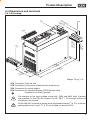
2.4 Dimensions and terminals
2.4.1 A Housing
A
X1
tor
era
Op ver
ith o
W ith C
W
A
X4
A
X2
L
PE
a
W
++
L3
/L2
1N
B
158 mm
6.2 in
144 mm
5.7 in
-
o
eK
Di ntlad g
e eträ e
b in F z s ei na
E hut s al aß sig
sc t al tzm Ìäs
is chu zul
S icht
n
X1
PE
U
V
W
T
PB
PA
1T2
mm
175 6.9 in
mm
185 7.3 in
m
5m
0.2
in
mm
76 .0 in
3
Weight 1/2 kg / 1 lb
X1A
X1B
X2A
X4A
Connection from the line
Connection to the motor, brake resistor, temp sensor
Connection for control cables
Connection for Operator/display HSP5-Service cable
Connection for shield / ground
Pay attention to the input voltage, since both 230V and 460V units (3-phase)
are possible. On the 230 VAC sytems The PA, PB, T1, T2 terminals will be not
included on the inverter.
On the 460 VAC inverters a jumper must be placed between T1 & T2 if a thermo
sensing device isn’t used. T1 & T2 are located on terminal X1B.
9
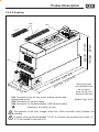
Product Description
2.4.2 B Housing
X2A
wi
th
X4
wi
th
Co
Op
er
ve
A
r
BA
ato
r
L
RA
C
SI
NE
GE
C
O
E
T
R
3
2
1
159,5 mm / 6,28 inch
173,5 mm / 6,83 inch
4
IV
ar
W
5
B
t
No PC
for
6
M
de
on eit
e K ez m
Di ntlad gt 5 le
e eträ eh
b in F tz s
E hu al
sc t als tzm
is chu zul
S icht
n
1
1 7
1 8
2 9
2 0
2 1
23 2
1 9
1 0
1 1
1 2
1 3
1 4
16 5
7
8
X1
A
L1
L2
L3
+
-
PB
U
V
W
T1
T2
53
116 00
014 1B-2A
5.G
m
m
10
10.F
90
2
5m
mm
m
/3
,54
inc
0m
inc
h
inc
h
66
/8,
22
/0
,2
m
h
nc
7i
,2
/8
h
X1A Connection from the line, motor, braking resistor and
temperature sensor/switch
X2A Connection for control cables
X4A Connection for Operator/display HSP5-Service cable
Connection for shield / ground
Mounting holes
are centered from
left to right at
both the top and
bottom of the unit
Weight 2 kg / 4 lb
Pay attention to the input voltage, since both 230V and 460V units (3-phase) are
possible.
A jumper must be placed between T1 & T2 if a thermo sensing device isn’t used.
T1 & T2 are located on terminal X1A.
10
Product Description
2.4.3 D Housing
X2A
-B
F5
X4A
-G
t
No r PC
fo
F5
ar
W
180.5 mm 7.11 inch
* 194.5mm 7.66 inch
de
on eit
e K ez m
Di tlad gt 5 le
en trä eh
be in F tz s
E hu al
sc t als tzm
is chu zul
S cht
ni
X1A
L1
L2
L3
+
-
PB
U
V
W
0402 0
9508 C-122
5.S0
90
5m
m
mm
0
3.5 .2 inc
h
4 in
ch
07.F
24
m
5m
5
9.6
m
4
9.8
0m
25
X1A Connection from the line, motor, braking resistor and
temperature sensor
X2A Connection for control cables
X4A Connection for Operator/display HSP5-Service cable
Connection for shield / ground
h
inc
h
inc
Mounting holes
are centered from
left to right at
both the top and
bottom of the unit
Weight 3 kg / 6.6 lb
Pay attention to the input voltage, since both 230V and 460V units (3-phase) are
possible.
A jumper must be placed between T1 & T2 if a thermo sensing device isn’t used. T1
& T2 are located on terminal X1A.
11
Installation and Connection
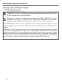
3. Installation and Connection
Enclosure type:
IP20/ Open Type
Operation temperature:
-10...45 °C / 14...113°F
Storage temperature:
-25...70 °C / -13...158°F
max. heat sink temperature:
90 °C / 194°F
Climatic category:
3K3 in accordance with EN 50178
Relative humidity:
max. 95 % without condensation
Power derating for high altitude:
1% for every 100m/330ft
above 1000m/3300ft
Maximum altitude for operation:
2000m / 6,600ft
Installation requirements:
150
6”
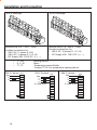
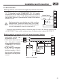
3.1 Control Cabinet Installation
30
1”
START
ENTER
F/R
START
FUNC.
ENTER
SPEED
F/R
STOP
FUNC.
SPEED
STOP
ANTRIEBSTECHNIK
ANTRIEBSTECHNIK
100
4”
• Mount in a stationary location with low vibration. Contact KEB
when mounting on a moving system.
• Adhere to minimum clearance distances in diagram 3.1.
Dia. 3.1
Multiple units can be mounted side by side with zero clearance.
• Most units have forced airflow from bottom to top using a thermostatically controlled
variable speed fan. Leave space above and below the unit for proper air flow.
• Prevent dust or debris from entering the unit, especially during the construction of the
control panel. Metal chips can cause internal shorts or malfunctions.
• Installation in a sealed enclosure requires proper cooling, be sure to over size control
cabinet or provide suitable cooling device.
• Protect the unit against conductive and corrosive gases and liquids.
• Water, mist, or steam should not be allowed into the unit.
• Do not allow water to condense within the unit
• The COMBIVERT F5 must not be installed in a “Explosion Proof” environment.
12
Installation and Connection
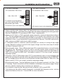
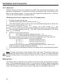
3.2 Good EMC Installation Techniques
1)
Mount the COMBIVERT F5 on a conductive
(zinc or nickel plated not painted) subpanel.
This sub plate serves as the central grounding
point for the machine.
2)
Always connect the shield of motor and
control cables with maximum surface area,
use a metal cable clamp to contact cable
shield on all sides. Using a single strand of
the shield or the drain wire from the shield
as the only connection can reduce the
shield’s effectiveness by 70%.
3)
The distance between control and power
cables should be at least 10..20 cm / 4...8
inches.
4)
Keep the motor and power cable spatially
separated especially if running parallel.
5)
If it cannot be avoided, cross control and
power cables and motor cables at a right
angle.
6
2
6
1
2
3
10-20cm
4...8 in
4
6)
Install all cables as close as possible to the
mounting plate - ideally in a metal wireway.
7)
90°
Ridged metal conduit can be used as a
shield for the motor cables. Always observe
the following points:
• Remove all paint from the control panel where the conduit is to be secured.
• Securely fasten all conduit fittings.
• Run only the motor wires through the conduit. All other wires must be pulled
through a separate conduit.
• Connect the control panel to the sub panel with a heavy ground strap.
8)
If a KEB EMI (CE) filter is used, it must be mounted as close as possible and to the
same subpanel as the COMBIVERT F5 motor control. The filter must have large bare
surface contact with the subpanel. Use only the wires from the filter to connect to the
inverter. Never add additional lengths of wire.
9)
All ground connections should be as short as possible. Always avoid creating ground
loops. NEC requires a ground conductor connected to every COMBIVERT F5 controller
in spite of the metal on metal connection to the subpanel.
5
You can find further instructions regarding EMC and proper wiring considerations by
contacting KEB technical support or visiting the web site www.kebamerica.com.
13
Installation and Connection
3.3 Connection of Power Circuit
3.3.1 Wiring instructions
RISK OF ELECTRIC SHOCK! Always disconnect supply voltage before servicing the
COMBIVERT F5. Wait 5 minutes before attempting to change the connections as the
DC Bus capacitors may still be charged.
Absolutely pay attention to the nameplate voltage of the KEB COMBIVERT and the
connected line voltage. A 230V-unit will be immediately destroyed on a 460V-power
supply. Never exchange the line and motor cables. The unit will be destroyed.
The COMBIVERT F5 motor controls specified in this manual are suitable for use on a circuit
capable of delivering not more than 10kA rms symmetrical ampers at the rated maximum
voltage.
Connection of the F5 series motor control to voltage systems configured as corner grounded
delta, center tap grounded delta, open delta, or ungrounded delta may defeat the internal
noise suppression. With this type of voltage supply the maximum phase to ground voltage is
300VAC for 230 VACrms units and 500 VACrms for 600VAC units. A balanced, center ground
wye connection is always recommended. The three phase voltage imbalance must be less
than 2% phase to phase. Greater imbalance can lead to destruction of the unit.
14
Installation and Connection
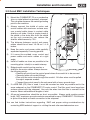
3.3.2 Terminal X1.A & Line Connection
A Housing:
-E
L3
L1 2
L
7
A Housing:
L3
L2
L1
GND
L3
N
L1
PE
X1.A
-++
L3
L2/N
L1
PE
++
X1.A
-++
L3
L2/N
L1
PE
Line connection
230 V 3-phase
& 460 V 3-phase
--
Line connection
230 V 1-phase
/L2
A Housing:
L2
L1
GND
++
Steps to wire the connectors
•Remove the connector from the inverter housing
by grasping it firmly and pulling straight out
•The maximum wire gauge is 14 awg or 1.5mm
•Strip the insulation back 0.25 in (7mm)
•The use of ferrules is optional
•Press a flathead screwdriver into the
upper slot
•Slide the bare wire into the lower slot
•Remove the screw driver and check
the wire connection by pulling back
on the wire to ensure it stays
Terminal strip X1A
Provides connections for:
• 230 VAC/1-phase (L1,L2/N)
• 230 VAC/3-phase (L1, L2/N,L3)
• 230 VAC/DC-Supply 250...370 V DC (++, --)
• 460 VAC/3-phase (L1, L2, L3)
• 460 VAC/DC-Supply 420...720 V DC (++, --)
15
Installation and Connection
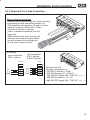
B & D Housings:
L1
N/L
2
B & D Housings:
L1
L3
++
--
PB
U
V
L2
L3
++
--
PB
W
U
V
T1
T2
Terminal strip X1A / 230 V - class
Provides connections for:
• 230 V AC / 1-phase (L1/L2)
• 230 V AC / 3-phase (L1, L2, L3)
• DC-Supply 250...370 V DC (++, --)
•
•
•
++, PB
U, V, W
T1, T2
Line connection
230 V 1-phase X1A
PE
L1
N/L2
W
L3
++
GND
L1
L2
--
PB
U
V
W
T1
T2
16
W
T1
T2
Terminal strip X1A / 460 V - Class
Provides connections for:
• 460 V AC / 3-phase (L1, L2, L3)
• DC-Supply 420...720 V DC (++, --)
Braking resistor
Motor
Temperature sensor/Switch
*Jumper T1/T2 if no temperature sensing device
Line connection
Line connection
460 V 3-phase
230 V 3-phase X1A
X1A
GND
L1
L2
L3
3 x 230 V AC
PE
L1
N/L2
L3
++
-PB
U
V
W
T1
T2
GND
L1
L2
L3
3 x 460 V AC
PE
L1
L2
L3
++
-PB
U
V
W
T1
T2
Installation and Connection
A, B, and D Housings:
A,B, and D Housings:
DC-connection 230 V-class
250...370 V DC
+
-
For branch circuit protection
use fuses rated for DC voltage.
(Bussmann type FWP)
X1A
PE
L1
N/L2
L3
++
-PB
U
V
W
T1
T2
*X1A terminal layout varies depending on housing
DC-connection 460 V-class
420...720 V DC
+
-
X1A
PE
L1
L2
L3
++
-PB
U
V
W
T1
T2
*X1A terminal layout varies depending on housing
• Always note the rated voltage, select the appropriate over current protection devices, select
a disconnect device, and select the proper wire size before beginning the wiring process.
Wire the COMBIVERT F5 according to NEC Class 1 requirements.
• Always use UL listed or CSA approved copper wire with a minimum temperature rating of
75°C. The wire gauge listed in the tables in section 2.3 is based on the maximum fuse rating,
copper wire and a 75°C insulation rating (THHW or equivalent). If a lower level of over current
protection is used, it may be possible to reduce the size of the wire. Use 300V rated wire for
230V systems and 600V rated wire for 460V systems.
• A disconnect switch or contactor shall be provided as a means of turning off the supply
voltage. Repetitive cycling on and off of the supply voltage more than once every 5 minutes
can lead to damage of the unit.
• B Housing and Larger: Class J (Bussmann type LPJ or equivalent) fuses or a circuit breaker
with type D trip characteristic must be used to provide branch circuit protection of the
COMBIVERT F5. The voltage rating of the fuse or circuit breaker shall be at least 250V for
230V units and 600V for 460V units. See tables in section 2.3 for over current protection
amperage ratings.
• A Housing: Class CC (Bussmann type LP-CC or equivalently) fuses or a circuit breaker with
type D trip characteristic must be used to provide branch circuit protection of the COMBIVERT
F5. The voltage rating of the fuse or circuit breaker shall be at least 250V for 230V units. See
table in section 2.3 for over current protection amperage ratings.
• B Housing and Larger: Terminal tightening torque for the power terminals is 0.5 Nm / 4 lbin
• A: Housing: Power connection must be installed as indicated on the previous page. Always
be sure to double check power connections for tightness.
• For installation requiring line side ground fault protection (GFI) consult KEB.
• Line chokes can be used to reduce harmonics, conducted high frequency noise, and can
extend the lifetime of the unit. Consult KEB for more information.
17
Installation and Connection
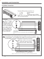
3.3.3 Motor Connection
A Housing:
PE
U
V
Terminal X1B provides connections for:
•
++, PB
Braking resistor
•
U, V, W
Motor
•
T1, T2
Temperature sensor/Switch
NOTE: The T1/T2 terminals aren’t present on the 230
VAC A-housing inverters.
W
PA
PB
T
T1
2
A Housing:
The maximum
motor
cable
length listed in
the tables in section 2.3
is based on several
factors: use of shielded
motor cables, ground
current limitations,
increased EMI noise
levels, voltage peaks at
the motor terminals.
M
3~
X1.B
PE
U
V
W
PA
PB
T1
T2
PE
U
V
W
-The PA, PB, T1, and T2 terminals aren’t present on the 230 VAC AHousing models.
-If terminals T1/T2 aren’t used a jumper needs to be installed between
them.
B & D Housings:
The maximum motor cable length listed in the tables in section 2.3 is based
on several factors: use of shielded motor cables, ground current limitations,
increased EMI noise levels, voltage peaks at the motor terminals.
Connect shield to the mounting
plate with maximum surface
area (use metal cable clamp)
M
3~
W
PE
U
V
X1A
L1
N/L2
L3
++
-PB
U
V
W
T1
T2
Motor-temperature sensor is optional
(can be NC switch or PTC type sensor)
NOTE: If terminals T1/T2 aren’t used a jumper needs to be installed between them.
18
Installation and Connection
3.3.4 Motor Overload Protection
The COMBIVERT F5 motor control by default provides motor overload protection at 130% of
the unit’s rated output current. See tables in section 2.3 for rated output current. Two additional
motor overload protection systems are available.
Electronic Motor Overload Protection
This software function provides speed dependent I2t overload protection and is approved
by UL as a solid state overload protection device according to UL508C section 42 and NEC
430 Part C. The trip current is adjustable as well as whether the motor is self cooled or
blower cooled.
Motor Winding Temperature Sensor
• Connects to Terminals T1, T2. These terminals as default need to be jumpered.
• Trip resistance level 1.65...4 kOhm
• Reset resistance level 0.75...1.65 kOhm
• This function can be activated or deactivated through a software parameter. The default
setting is On.
• Do not run sensor wires in the same conduit or wire way as other control cables. These
sensor wires most likely are carrying high frequency noise from the motor.
• If the sensor wires are part of the motor cable they must be shielded independently from
the motor wires.
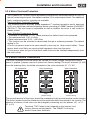
3.3.5 Motor Terminal Connections
The motor connections should always be verified for correct voltage configuration before
power is appiled. (jumpers may be in place from factory testing) The motor terminals (U,V,W)
from the indexing drive, should be connected to the motor terminals U1, V1, W1.
No Connection
Delta Connection
Wye Connection
U1
W2
U1
W2
U1
W2
V1
U2
V1
U2
V1
U2
W1
V2
W1
V2
W1
V1
No jumpers in place
230V
Jumper setting
460V
Jumper setting
The ground terminal at the motor should be connected to the ground terminal on the inverter.
The motor cables should be shielded and the sheild should be connected to the inverter. The
direction of rotation of the motor can be changed by reversing any two phases. (U1 to V1,
V1 to U1)
Terminals T1&T2 need to be jumpered on the inverter if not
using a thermo sensing device. The 230VAC A-Housing
doesn’t have these terminals.
19
Installation and Connection
3.3.6 IMC Motors
Hp
1/8
1/6
1/4
Operating Voltage
230V/460V
230V/460V
230V/460V
1/3
230V/460V
1/2
230V/460V
3/4
230V/460V
1
230V/460V
1.5
230V/460V
2
230V/460V
3
230V/460V
4
230V/460V
5
230V/460V
7.5
10
230V/460V
230V/460V
Speed [RPM]
1690
1685
1685
1640
1690
1685
1685
1710
1710
1710
1710
1720
1720
1710
1710
1720
1720
1730
1735
1735
1720
1720
1750
Mounting Configuration
IEC 56-B14
IEC 63-B14
IEC 63-B14
IEC 71-B14 (square)
IEC 71-B14
IEC 71-B14
NEMA 56C
IEC 80-B14
NEMA 56C
IEC 80-B14
NEMA 56C
IEC 90-B14
NEMA 145TC
IEC 90-B14
NEMA 145TC
IEC 100-B14
NEMA 182TC
IEC 100-B14
IEC 112-B14
NEMA 182TC
IEC 112-B14
NEMA 213TC
IEC 112-B14
Motor Part Number
92C81286010000
92C81286020000
92C81286030000
92C49952070000
92C49952080000
92C49953170000
92C49953180000
92C49954080000
92C49954090000
92C49955430000
92C49955410000
92C49956230000
92C49956220000
92C49957340000
92C49957330000
92C49958240000
consult factory
92C81285010000
92C49959260000
92C49959280000
consult factory
consult factory
consult factory
The above motors are also rated to operate on European 220V/380-50Hz or
230V/400V-50Hz systems. When operating on these types of voltage
supplies, parameter CP.5 must be set to 50.0 for proper motor operation.
3.3.7 EMI(CE) Filters
The KEB COMBIVERT frequency inverters are optionally available with EMI filters. If
you have a 1/2, 1, 2 Hp 460VAC system your unit comes equipped with this item. These
filters allow the KEB COMBIVERT to meet CE EMC directive 89/339. All filters are
dimensioned for the inverter’s rated current and are designed to meet the conducted
emission limit as defined by EN55011/B.
The filter kits contain all required hardware for installation. The filters include the
sheilded supply wires which connect the filter to the inverter. Depending on the
available space and filter type, the filter can either be installed under the frequency
inverter (Back Mount), or beside the frequency inverter (Panel Mount).
Voltage
Class
230
230
230
460
460
460
460
VAC
VAC
VAC
VAC
VAC
VAC
VAC
20
Phases
Filter Kit
1
1
3
3
3
3
3
92C84982210000
92C84982220000
92C84982230000
92C84982240000
92C84982250000
92C84982260000
92C84982270000
EMI (CE) Filters
Mounts with
Inverter size
05 & 07
09 & 10
12
10
12
13
14
Back
Back
Back
Back
Back
Back
Style
Panel Mount
Mount/Panel Mount
Mount/Panel Mount
Mount/Panel Mount
Mount/Panel Mount
Mount/Panel Mount
Mount/Panel Mount
Dimensions [in]
[HxWxL]
1.6x3.5x9.8
1.6x3.5x9.8
1.6x3.5x11.2
1.6x3.5x9.8
1.6x3.5x9.8
1.6x3.5x11.2
2.0x3.5x11.2
Installation and Connection
3.3.8 CAM Gear Box
Limit Switch
Keyway
Type II Extra
CAM LOBE
A standard Roller Gear unit with the CAM &
Limit Switch mounted on the correct keyway
position directly opposite of the output shaft,
90 degrees(clockwise or counter clockwise)
from the CAM Lobe. The CAM & Limit Switch
may also be mounted on the reducer. *If the
unit has a “Type II” motion, a special Limit
Switch CAM is needed with one extra Lobe,
180 degrees from the first Lobe. (as shown)
Limit switch
A standard right angle unit with the CAM &
Limit Switch mounted on the housing has a
correct keyway position directly opposite of the
CAM Lobe. CAM & Limit Switch may also be
mounted on the reducer.
Keyway
Keyway
A standard parallel unit with the CAM & Limit
Switch mounted on the housing has a correct
keyway position directly opposite of the output
shaft, 90 degrees (clockwise or counter
clockwise) from the CAM Lobe. CAM & Limit
Switch may also be mounted on the reducer.
Limit switch
For the correct dwell location of the cam or input shaft keyway see the IMC
CAMCO-Ferguson assembly drawing for your unit.
21
Installation and Connection
3.4 Breaking Resistor
3.4.1 Explanation
The COMBIVERT F5 inverter can be equipped with an external braking resistor for
limited 4 quadrant operation. The energy the motor regens into the inverter during deceleration is dissipated through the internal braking transistor to the braking resistor.
The braking resistor heats up during braking. If it is installed inside a control
cabinet, sufficient interior cooling must be provided! The resistor should be
mounted above and a minimum of 9 inches away from the inverter or in a separate
enclosure!
3.4.2 Options
Voltage Recommended
Class
Inverter Size
230 V
230 V
230 V
230 V
460 V
460 V
460 V
460 V
460 V
09
10,12
05
07
09
10
12,13,14
Minimum
Inverter
Size
09
09
10
12
05
07
07
10
10
Panel Mount Braking Resistors
Kit Number
Resistance Rated
[Ù]
Power
[W]
92C84982410000
92C84982420000
92C84982430000
92C84982440000
92C84982450000
92C84982460000
92C84982470000
92C84982480000
92C84982490000
100
68
33
27
390
270
150
110
85
82
120
250
300
90
130
230
350
410
Peak
Power
[W]
Dimensions [in]
[HxWxL]
1500
2200
4400
5400
1500
2100
3700
5000
6500
1.57x.95x9.5
1.57x.95x11.8
3.15x1.00x11.8
3.15x1.0x15.75
1.57x.95x9.5
1.57x.95x11.8
3.15x1.00x11.8
3.15x1.0x15.75
3.15x1.0x15.75
Peak power is classified as the peak repetitive power dissipation with a 6 sec
on time and 120 sec cycle time. KEB can offer many types of braking
resistors, please contact your sale representative for more information.
Kit Number
92C84982510000
92C84982520000
92C84982530000
Back Mount Braking Resistor
Voltage Class Inverter Size Resistance Rated Power Peak Power
[Ù]
[W]
[W]
230 V
460 V
230 V
460 V
230 V
460 V
9
10
10
12
12
13,14
160
35
82
35
82
35
900
3400
1700
6650
1700
6650
Peak power is classified as the peak repetitive power dissipation with a 3 sec
on time and 120 sec cycle time. The Back Mount Breaking Resistor adds 1.2
inches onto the height of the inverter.
22
Installation and Connection
3.4.3 Connection
Braking resistor connection with high temperature drive fault
• The resistor has a PTC type sensor and is connected to the
T1, T2 ter minal on the COMBIVERT F5. If a motor
temperature sensor and braking resistor sensor is used they
should be placed in series. Note: if the braking transistor in
the unit fails, there is no guarantee the voltage to the resistor
will be shut off!
twisted wires
= 90°C
(180°C)*
Braking resistors can develop very high surface
temperatures, therefore install away from other
devices, above the motor control and where people
can not inadvertently come in contact with it.
X1A
L1
N/L2
L3
++
-PB
U
V
W
T1
T2
* The panel mount breaking resistors listed on page 22 have a NC thermal contact rated
at 180°C/356°F. Back mount resistors have a thermal contact rated at 90°C/194°F.
Braking resistor connection with high temp disconnect feature
• The resistor has a NC
mechanical switch type
temperature sensor.
• If the resistor becomes too
hot, the sensor switch
opens and disconnects the
COMBIVERT F5 from the
supply voltage.
• In the event of a complete
failure of the internal
braking transistor, this is
the only way to disconnect
the resistor from the power
source!
PA
PB
U
= 90°C
OH1
OH2
X1A
L1
N/L2
L3
++
-PB
U
V
W
T1
T2
120 or 24 V AC/DC
23
Installation and Connection
3.4.4 Selection
Different braking resistors are available from KEB. They are selected according to their
application requirements. The selection formulas and technical data of the resistors are
listed on the following pages. In most cases the suggested braking resistor is sufficant.
This can be verified using the procedure below.
*Braking resistors aren’t required on 1/3 to 1 HP applications
1. Establish desired braking time.
2. Calculate braking time without braking resistor (tBmin).
3. If the desired braking time is shorter than the calculated braking time, it will be necessary to use a braking resistor. (tB < tBmin)
4. Calculate braking torque (T B ) taking the load torque (T L ) into
account. TL is a positive value for friction and windage and negative for overhauling loads.
5. Calculate peak braking power (PB). This must always be calculated for the "worst
case" (nmax to standstill).
6. Selection of the braking resistors:
a)
The resistor should be selected so that PR > PB.
b)
PN is to be selected according to the duty cycle factor (d.c.f.).
The braking resistors may only be used for the specified value. The maximum
ON period of the braking resistor may not be exceeded.
6 % d.c.f. =
maximum braking time 8 s
25 % d.c.f. =
maximum braking time 30 s
40 % d.c.f. =
maximum braking time 48 s
Longer ON periods require specially-designed braking resistors. Take into ac
count the current through the braking transistor.
7. Check whether the desired braking time is attained with the selected braking resistor
(tBmin).
Note: Consider the capacity of the braking resistor and motor. The braking torque may
not exceed the rated torque of the motor by more than 1.5 times. To realize maximum
possible braking torque, the frequency inverter must be sized for the increased motor
current.
Braking time
The braking time is adjusted in the frequency inverter through the deceleration parameters. If the selected deceleration time is too short, either the peak inverter current level
or the maximum DC bus voltage will be exceeded. The error message E.OC or E.OP will
result. The following formulas can be used to determine an allowable braking time.
24
Installation and Connection
Formulas
1. Braking time without braking
resistor
2. Braking torque (required)
(JM + JL) • (n1 - n2)
tBmin =
307 • (K • TN + TL)
Valid range: n1 > nN
(field weakening)
- TL
(307 • tB)
Conditions: TB - 1.5 • TN
f < 1.4 x rated frequency of motor
3. Peak braking power
4. Braking time with braking resistor
(JM + JL) • (n1 - n2)
T B • n1
tBmin =
PB =
307 • K• TN+ TL+
7.04
Conditions:
(JM + JL) • (n1 - n2)
TB =
(
PB < PR
Valid range:
(PR • 7.04)
(n 1 - n2)
)
n 1 > nN
PR • 9.55
Conditions:
On period
d.c.f.
ON period d.c.f for cycle
time tZ < 120 s
- TN • (1.5 -K)
(n1 - n2)
f < 1.4 x rated frequency of motor
PB < PR
f
tB
d.c.f =
• 100 %
tZ
ON period d.c.f for cycle
time tZ > 120 s
tB
d.c.f =
• 100 %
120 s
Definitions
K = 0.25 for motors
0.20 for motors
0.15 for motors
0.08 for motors
0.05 for motors
t
tB
tZ
up to 2 hp
3 to 5 hp
7.5 to15 hp
20 to 60 hp
75 to 400 hp
Moment of inertia of the motor [lb ft2] TB = Braking torque (required) [ft lbs]
Moment of inertia of the load [lb ft2] TL = Load torque [ft lbs]
Motor speed before deceleration [rpm] tB = Braking time (required) [s]
Motor speed after deceleration [rpm] tBmin= Minimum braking time
(Stand still = 0 rpm)
t Z = Cycle time
nN = Motor rated speed [rpm]
PB = Peak braking power
TN = Motor rated torque [ft lbs]
PR = Peak power dissipation of the resistor
JM =
JL =
n1 =
n2 =
[s]
[s]
[W]
[W]
25
Installation and Connection
3.5 Control Circuit: F5-BASIC
X2A
1
5
7
8
10 11 14 15 16 20 22
24 25 26 27 28 29
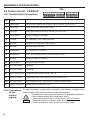
3.5.1 Terminal Strip Connections
PIN
1
Function
Description
+ Analog input 1
Voltage input for speed control, resolution:11 Bit, 0...±10 VDC, scan time: 2 ms
5
Analog Output
Outputs 10 VDC when motor speed is 0 rpm
7
+10V Output
Analog supply voltage for speed ref. +10 VDC ±5%, max. 4 mA
8
Analog Common
Common for analog In- and Outputs
10
Quick Stop
0 V = Quick Stop, +24 V = Normal Operation
11
Stop Signal
Stop Signal: +24 V pulse starts stop sequence
14
Start Signal
Momentary signal starts index
15
Direction Select
0 V = Forward, +24 V = Reverse
16
Control Release
+24 V = Drive enabled; Drive fault reset when signal removed
20
24V-Output
Approx. 24V Output (max.100 mA)
22
Digital Common
Common for digital In-/Outputs
24
Relay 1, NO contact
Fault Output
25
Relay 1, NC contact
Drive Ready
26
Relay 1, switching cont.
Switching Constant, Ratings: max. 30 V DC, 1 A
24
Relay 2, NO contact
Programmable Relay; Actual Frequency (CP.22) > Level (CP.23)
25
Relay 2, NC contact
Actual Frequency(CP.22) < Level (CP.23) *** Default Zero Speed Output ***
26
Relay 2, switching cont.
Switching Constant, max. 30 V DC, 1 A
3.5.2 Connection In order to prevent a malfunction caused by interference voltage on the
control inputs, the following steps should be observed:
of the
• Establish a common ground point for all ground connections.
control
• Use shielded cable with twisted pair wires.
signals
• Terminate shield wires to earth ground, only at inverter.
EMC • Separate control and power wires 8" or more apart.
• Control and power wires to cross at a right angle.
26
Installation and Connection
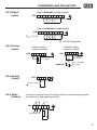
3.5.3 Digital
Inputs
Use of internal voltage supply
X2A 1
20 22
10 11 14 15 16
GND
Use of external voltage supply
X2A
1
10 11 14 15 16
Rin = 2.1 kΩ
22
GND
+
20...30 VDC Regulated
3.5.4 Analog
Inputs
Internal analog
speed ref. setting
X2A 1 5 7 8
External analog
speed ref. setting
22
GND
X2A 1 5 7 8
R = 3...10 kW
+
optional:
3.5.5 Analog
Output
X2A
1 5 7 8
22
+
22
GND
0...±10 VDC
Ri = 30 kW
0(4)...20 mADC
Ri = 250 W
GND
+10 VDC / 5 mA
3.5.6 Relay
Outputs
In case of inductive load on the relay output, protective wiring must be
provided (e.g. free-wheeling diode)!
X2A 24 25 26 27 28 29
GND
max.30VDC/1A
+
-
27
Installation and Connection
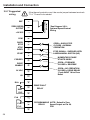
3.5.7 Suggested
wiring
1
REF
ZERO SPEED
OUTPUT
5
+10 VDC
7
COM
8
QUICK
STOP
10
STOP
INDEX
11
MOMENTARY PULSE
STARTS INDEX
16
DRIVE
ENABLE
OPEN = FORWARD
CLOSED = REVERSE
24 VDC
20
0V
22
25
RLB
28
FLB
27
FLA
FLC
29
28
DRIVE FAULT
RELAY
26
RLC
OPEN = NO OPERATION
CLOSED = DRIVE READY
*Cycle INPUT 16 for Error
Reset
24
RLA
STOP SIGNAL - SUPPLIED WITH
A MECHANICAL SWITCH (NO)
15
FOR/REV
*See Diagram 3.5.9 Optional Speed Control
Wiring
OPEN = QUICK STOP
CLOSED = NORMAL
OPERATION
14
START
Run Speed Adjust
(3K to 10K)
If the thermal protection won't be used a jumper between terminals
T1 & T2 need to be added.
PROGRAMABLE NOTE: Default is Zero
Speed Output on Pin 28,
RELAY
FLB
Installation and Connection
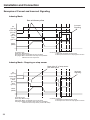
As a momentary signal is sent to INPUT 14 the drive indexes until it
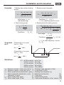
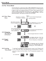
3.5.8 Operation
Explanation receives a signal on INPUT 11. On reception of signal on INPUT 11 the
drive either decelerates and stops or the stop point is delayed for a
positioning stop. This depends on the value entered in CP.27.
In the index mode, the start pulse
takes priority over the stop pulse.
Disabled Mode - Motor Voltage Off
ST
(pin 16)
Quick Stop
(pin 10)
Start
(pin 14)
6ms minimum pulse
Stop
(pin 11)
Motor
(RPM)
ST: Loss of signal shuts off the motor voltage - the motor will coast to a stop
Quick Stop: Ignored
Start pulse: Ignored
Drive reactivates into indexing mode - motor stopped condition
Stop signal: Ignored
or Quick Stop mode depending on Quick Stop input!
Quick Stop Mode - Stop Motor
6ms minimum delay between
Quick Stop and Start
ST
(pin 16)
Quick Stop
(pin 10)
Start
(pin 14)
Stop
(pin 11)
6ms minimum
pulse
Motor
(RPM)
ST: Must be high
Quick Stop: Loss of signal decelerates the load to a stop
Start pulse: Ignored
Drive reactivates into indexing mode - motor stopped condition!
Stop signal: Ignored
29
Installation and Connection
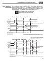
Examples of Correct and Incorrect Signaling
Indexing Mode
6ms minimum pulse
Incorrect
Signaling
ST
(pin 16)
Quick Stop
(pin 10)
Start
(pin 14)
Stop
(pin 11)
Motor
(RPM)
ST: Must be high
Quick Stop: Must be high
Start pulse: Motor accelerates and runs at speed
Stop signal: Motor decelerates and stops at a repeatable
distance from the stop sensor
* Incorrect singaling
1. Start pulse overrides the stop signal
2. Start input must be low for stop signal to function
Indexing Mode - Stopping on stop sensor
Must drive off of stop sensor
with start signal
ST
(pin 16)
Incorrect
Signaling
Quick Stop
(pin 10)
Start
(pin 14)
Stop
(pin 11)
Motor
(RPM)
ST: Must be high
* Incorrect singaling
Quick Stop: Must be high
1. Start pulse overrides the stop signal
Start pulse: Motor accelerates and runs at speed
2. Start input must be low for stop signal to function
Stop signal: Motor decelerates and stops at a repeatable
distance from the stop sensor (sensor still made)
30
REF
COM
+10V
REF
COM
3.5.9 Optional
Speed Control
Wiring
+10V
Installation and Connection
7
1
8
7
1
8
CP10
CP10
Single preset
speed
+10V
REF
COM
+10V
REF
COM
Potentiometer
3K to 10K Ohm
7
1
8
7
1
8
CP10
CP10 = max
frequency
CP9
CP9
+
-
CP9 = low
frequency
PLC
Dual preset
speeds
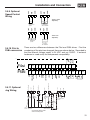
There are two differences between the F4si and F5Bi drives. First the
numbering of the pins has changed, these are shown below. Seconded is
that the internal voltage supply is 24 VDC and not 15VDC. If external
hardware is used verify the compenants compatiblity.
6
1
2
3
F5Bi
1
5
7
8
10
11
14
15
16
20
22
24
25
26
START
FOR/REV
Start
Forward/Reverse
+10V
REF
COM
11
10
14
15
7
1
8
Start
Pulse
Stop
Switch
S1
29
S1
see speed select
options
Jog
Jog
direction
S1
open = no operation
closed = drive ready
28
S1
Quick
Stop
Drive
Enable
RLA
24 VDC
Quick Stop
20
Stop Index
REF
Drive Enable
16
+24V
3.5.11 Optional
Jog Wiring
27
FLC
11
FLB
14
COM
RLC
12
FLA
13
RLC
5
RLB
4
0V
9
DRIVE
ENABLE
7
STOP INDEX
10
+10 VDC
8
ZERO SPEED
OUTPUT
F4si
QUICK
STOP
RLB
RLA
3.5.10 F4si to
F5Bi conversion
PLC source
0 to 10VDC
Ri = 4K Ohm
open = forward
closed = reverse
S1: AUTO/JOG Selector, 3PDT
shown in AUTO position
Index
direction
Not used if index is
always forward
31
Operation of the Drive
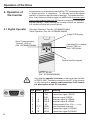
4. Operation of
the inverter
As an accessory for displaying and editing "CP" parameter values,
a "digital operator" is necessary. To remotely mount the digital
operator, a operator remote cable is required. To prevent malfunctions, the inverter must be brought into nOP status (remove signal
from control release terminal 16) before connecting / disconnecting the operator. When starting the inverter without an operator,
it is started with the last stored values.
4.1 Digital Operator
Standard Operator: Part No. 92C84982310000
Serial Operator: Part No. 92C84982320000
5-digit LED Display
Serial Communication
Transmit "LED on"
(Ref.: 92C84982320000)
Operating-Error display
Normal "LED on"
Error "LED blinks"
START
ENTER
FUNC.
F/R
SPEED
STOP
Double function keypad
ANTRIEBSTECHNIK
RS232, RS485
(Ref.: 92C84982320000)
Only use the operator interface for the serial data transfer
to RS232, 485. The direct connection from PC to the inverter
is only valid with a special cable otherwise it will lead to
the destruction of the PC-interface!
5
4
9
32
3
8
2
7
1
6
PIN RS485 Signal
1
–
–
2
–
TxD
3
–
RxD
4
A'
RxD-A
5
B'
RxD-B
6
–
VP
7
C, C' DGND
8
A
TxD-A
9
B
TxD-B
Meaning
reserved
Transmitter signal, RS232
Receiver signal, RS232
Receiver signal A, RS485
Receiver signal B, RS485
Voltage supply-Plus +5V (Imax = 10 mA)
Data reference potential
Transmitter signal A, RS485
Transmitter signal B, RS485
Operation of the Drive
4.1.1 Keypad
When switching on the KEB COMBIVERT F5, the value of parameter CP.1
appears in the operator display. (see "Drive Mode" to switch the keypad
function)
The function key
(FUNC) changes
between the
parameter value and
parameter number.
) and
With UP (
DOWN ( ), the
value of the
parameter number
is increased or
decreased.
Generally; when a value is changed, parameter values are immediately
accepted and stored nonvolatile. However, with some parameters it is not
useful that the adjusted value is accepted immediately. In these cases the
adjusted value is accepted and stored nonvolatile by pressing ENTER.
If a drive fault occurs during operation, the display changes to the drive
fault message. The drive fault message in the display is cleared by
pressing ENTER.
error
Pressing ENTER only clears the fault message in the display. In
the Inverter status display (CP. 2), the fault is still displayed until
the inverter has been reset. In order to reset the fault itself the
cause must be identified and removed, than a reset signal applied
to terminal 16, F5-Basic, or a power-on reset (cycle supply voltage
off and then on) must occur.
33
Operation of the Drive
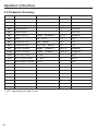
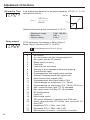
4.2 Parameter Summary
Display
Parameter
Setting Range
Resolution
Factory Setting
CP.0
Password Input
0 ... 9999
1
Read Only
CP.1
Actual Frequency Display
-
.0125
Read Only
CP.2
Inverter State
-
-
Read Only
CP.3
Actual Utilization
-
1%
Read Only
CP.4
Peak Utilization
-
1%
Read Only
CP.5
Rated Frequency
0.0000 ... 400.0000 Hz
.0125 Hz
60.0000 Hz
CP.6
B o o st
0.0 ... 25.5 %
0.1 %
5.0 %
CP.7
Acceleration Time
0.00 ... 300.00 s
0.01 s
.15 s
.12 s
CP.8
Deceleration Time
-0.01; 0.00 ... 300.00 s
0.01 s
CP.9
Minimal Frequency
0.0000 … 70.0000 Hz
0.0125 Hz
20.0000 Hz
CP.10
Maximal Frequency
0.0000 … 70.0000 Hz
0.0125 Hz
60.0000 Hz
CP.14
Max. Ramp Current
0 …2 0 0 %
1%
200 %
CP.15
Max. Constant Current
0 …2 0 0 %
1%
200: off
CP.16
Speed Search Condition
0 …1 5
1
0: off
CP.17
Voltage Stabilization
1…650 V (off)
1V
LTK
CP.20
DC Braking Mode
0 …9
1
1: LS + actual value = 0
CP.21
DC Braking Time
0.00…100.00 s
0.01 s
.10 s
CP.22
Relay 2 Output Condition
0 …6 8
1
27: actual value> level
CP.23
Relay 2 Output Level
± 300000.00
0.01
0.10
CP.27
Positioning Delay
-0.02 ... 327.67 s
0.01 s
0.00 s
CP.35
Customer Rev. Iden.
0 ... 65535
1
1
CP.36
Customer Iden. Number
0 ... 65535
1
10141
1) LTK - depending on power circuit
34
Operation of the Drive
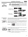
From the factory, the frequency inverter is supplied
without password protection, this means that all parameters can be adjusted. After programming, the unit can be
protected against unauthorized access thus preventing
the values from being changed.
4.3 Password
Input
FUNC.
SPEED
Locking the CPParameters (Read only)
START
ENTER
F/R
FUNC.
SPEED
FUNC.
SPEED
Releasing the
CP-Parameters
START
ENTER
F/R
FUNC.
SPEED
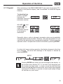
4.4 Operating
Displays
The parameters below provide the user with the ability to monitor various
operating characteristics of the drive. These parameters are very useful
during commissioning and trouble shooting.
Actual frequency
display
Display of the actual output frequency with a resolution of 0.0125 Hz. The
digital operator will display "noP" or "LS" if the enable (terminal 16) or the
direction of rotation (terminal 14 or 15) are not energized. The rotation of
the motor is indicated by the sign.
Output frequency 18.3 Hz, rotation forward
Examples:
Output frequency 18.3 Hz, rotation reverse
Inverter status
display
The status display shows the actual working conditions of the inverter.
Possible displays and their meanings are:
"no Operation" control release (terminal 16) signal removed,
modulation off, output voltage = 0 V, drive is disabled.
" Low Speed " no direction signal at F or R (terminal 14 or 15),
modulation off, output voltage = 0 V.
35
Operation of the Drive
"Forward Acceleration" drive accelerates with direction of
rotation forward .
"Forward Deceleration" drive decelerates with direction of
rotation forward.
"Reverse Acceleration" drive accelerates with direction of
rotation reverse.
"Reverse Deceleration" drive decelerates with direction of
rotation reverse.
"Forward Constant" drive runs with a constant speed and
direction of rotation forward.
"Reverse Constant" drive runs with constant speed and direction of rotation reverse.
Other status messages; such as error(E.xxx) and malfunction
(A.xx) codes, are described towards the end of this manual.
Actual inverter
load
Display of the actual inverter loading in percent. 100% rate of utilization is
equal to the inverter rated current. Only positive values are displayed,
meaning there is no difference between motor and regenerative operation.
Peak inverter load
CP.4 makes it possible to display the peak inverter loading during
operation in percent. Only positive values are displayed, meaning there
is no differentiation between motor and regenerative operation.
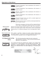
4.5 Adjustment of the
Drive
Rated frequency
The following parameters determine the fundamental
operating data of the drive. They should be checked and/or
adjusted for the application.
The inverter will output the applied input voltage or the voltage value
adjusted in CP.17 at the frequency value adjusted in this parameter. This
parameter is typically adjusted for the motor rated frequency. Note:
Motors can overheat when the rated frequency is incorrectly adjusted!
Adjustment range:
Resolution:
Factory setting:
36
0...400 Hz
0.0125 Hz
60 Hz
Adjustment of the Drive
Boost
In the lower speed range losses in the motor become greater. This
parameter can be used to boost the voltage in order to overcome these
losses. With proper adjustment, the torque output of the motor will remain
constant even at the lowest speeds.
U V
A
Adjustment range:
Resolution:
Factory setting:
0.0...25.5 %
0.1 %
5.0 %
0
CP.6
f
f
CP.5
Adjustment:
1) Determine the load level (CP.3) with no-load operation at the
rated frequency.
2) Then run at about 10 Hz and adjust the torque boost, so
that about the same load level (CP.3) is achieved as with the
rated frequency.
During continuous operation; if the motor operates at low speed
and too much voltage, it can lead to overheating of the motor.
Acceleration time
The parameter determines the time needed to accelerate from 0 Hz to
100 Hz. The actual acceleration time is proportional to the frequency
change (delta f).
100 Hz
f
–––––– x actual acceleration time = CP.7
delta f
100 Hz
Adjustment range:
Resolution:
Factory setting:
0.00...300.00 s
0.01 s
0.15 s
t
CP. 7
Example: actual acceleration time = 5s; the drive should accelerate from
10 Hz to 60 Hz, delta f = 60 Hz - 10 Hz = 50 Hz
CP.7 = (100 Hz / 50 Hz) x 5 s = 10 s
Deceleration time
The parameter determines the time needed to decelerate from 100 Hz to
0 Hz. The actual deceleration time is proportional to the frequency change
(delta f).
100 Hz
–––––– x actual deceleration time = CP.8
delta f
37
Adjustment of the Drive
f
100 Hz
Adjustment range:
Resolution:
Factory setting:
-1; 0.00...300.00 s
0.01 s
.12 s
t
CP. 8
By depressing DOWN arrow key, one increment passed the 0.0, the
display will show "=Acc". This means the same value stored in CP.7
(Decel=Accel time)!
Example: actual deceleration time = 5s; the drive should decelerate from
60 Hz to 10 Hz. delta f = 60 Hz - 10 Hz = 50 Hz
CP.8 = (100 Hz / 50 Hz) x 5 s = 10 s
Minimum
frequency
The frequency the inverter outputs with 0V applied to the analog input or
if the activated mode frequency is lower than this value.
Adjustment range:
Resolution:
Factory setting:
0...70 Hz
0.0125 Hz
20.0 Hz
f
CP.10
CP.9
0V
Maximum
frequency
VREF
The frequency the inverter outputs with 10V applied to the analog input.
Adjustment range:
Resolution:
Factory setting:
38
10V
0...70 Hz
0.0125 Hz
60.0 Hz
Adjustment of the Drive
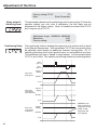
Max. ramp current
This function acts as an adjustable current limit during acceleration or
deceleration. It can be used to prevent the load current from exceeding the
inverter's peak current rating, thereby preventing shut down with an E.OC
fault. When the load level reaches the adjusted value, the acceleration
or deceleration is stopped until the load drops below the adjusted value.
Note: if this parameter is adjusted too low, the motor may not be able to
accelerate to full speed. The motor will run at a low speed. CP.2 displays
"LAS" when the function is active.
Adjustment range:
Resolution:
Factory setting:
Max. constant
current
0...200 %
1%
200 %
This function acts as an adjustable current limit when operating at a
constant speed. It can be used to prevent the load current from
exceeding the inverter's over current level, thereby preventing shut
down of the inverter with an E.OC fault. When the load level reaches
the adjusted value, the output frequency is reduced until the load drops
below the adjusted value, after which the frequency is increased again
to the previous value. Setting the value too low may prevent the motor
from running at the desired speed. CP. 2 displays "SSL" when the
function is active.
Utilization (CP.3)
Adjustment range:
Resolution:
Factory Setting:
0...200 % (off)
1%
200 % (off)
CP.14
CP.15
t
on
LAD-stop
off
t
on
Current limit
off
t
factual
fset
t
39
Adjustment of the Drive
Speed search
condition
When starting the frequency inverter into a spinning motor, an E.OC fault
can be triggered because of the difference between the actual motor
speed and the inverter set speed. By activating speed search, the inverter
searches for the actual motor speed, adjusts its output frequency to
match. It will then accelerate with the adjusted ramp time to the given set
value. During speed search CP.2 displays "SSF". This parameter determines under which conditions the function will operate. Parameter values
can be selected individually or any combinations.
Example: CP.16=12 means after reset or after auto-restart (E.UP).
Value
Condition
0
1
Function off
Control release enabled ( terminal 16 )
2
4
Power on
After fault reset
8
After auto-restart (reset) E.UP
Adjustment range:
Resolution:
Factory setting:
Note:
Voltage stabilization
0...15
1
8
Enter-Parameter
This parameter can be used to regulate the output voltage in relation to the
rated frequency. With this function active, voltage variations at the input
as well as on the DC bus will have only a small influence on the output
voltage (V/Hz-characteristic). This function can be used to adapt the
output voltage for special motors and can also prevent damage to the
motor resulting from over or under voltage supply.
Adjustment range:
Resolution:
Factory setting:
Note:
1...650 V (off)
1V
PSD
Enter-Parameter
PSD
(Power Stage
Dependent)
In the example below using a motor rated at 230 V / 60Hz, the output
voltage is too high due to our supply being 250 V and CP.17 off. By setting
CP.17 to the correct rated motor voltage of 230 V, the voltage is clamped
thereby giving the motor the correct voltage.
40
Adjustment of the Drive
If the supply voltage drops to190 V and CP.17=230 V, the inverter will still
provide rated voltage to the motor up until 190V. The output voltage can
not be increased further beyond the input therefore the motor will operate
in field weakening. To calculate at which frequency this will occur use the
following formula:
f = (60Hz/ 230 V)*190 V= 50 Hz
CP.17 = 230V
Vsupply = 190V
* Both scenarios above, it is assumed no boost (CP.6=0%).
DC-braking Mode
During DC-braking, the motor is not decelerated by a controlled ramp.
Quick braking without regen voltage can be achieved by applying a DC
voltage to the motor winding. Parameter values listed on the next page,
determine how the DC-braking is triggered.
Value DC-Braking Activation
0
1
Deactivated
Activates when direction signal is removed and the output
frequency has reached 0Hz. The braking time is dependent on
CP.21 or until the next direction of rotation.
2*
3*
Activates as soon as the direction signal is removed.
Activates as soon as the direction signal is removed or changed.
4*
Activates as soon as the direction signal is removed and if the
real frequency goes below 4 Hz.
5*
6*
Activates when the real frequency goes below 4 Hz.
Activates as soon as the set value goes below 4 Hz.
7
8
Reserved - No Function
Reserved - No Function
9
Activates before the acceleration ramp when a direction signal
is given. The time is dependent on CP.21.
* Braking time depends on the actual frequency.
Adjustment range:
Resolution:
Factory setting:
Note:
0...9
1
1
Enter-Parameter
41
Adjustment of the Drive
DC-braking Time
If the braking time depends on the actual frequency (CP.20 = 2...7), it is
f
calculated as follows:
100 Hz
tBrake =
CP.21 x f real
–––––––––
100 Hz
factual
t
Otherwise the braking time corresponds to CP.21.
Adjustment range:
Resolution:
Factory setting:
Relay output 2
tBrake CP.21
0.00...100.00 s
0.01 s
0.10 s
CP.22 determines the function of Relay Output 2.
Relay output 2 (terminal X2A.27...X2A.29)
The switching level of CP.22 is CP.23!
Value
0
1
2
3
4
5
6
7
8
9
10
11
12
13
14
15
16
17
18
19
20
21
22
23
42
Function
No function
On; active when unit has voltage applied to it
Run signal; also by DC-braking
Ready signal (no error)
Fault relay
Fault relay (no auto-reset)
Warning or error message at abnormal stopping
Overload alert signal
Overtemperature alert signal power modules
External Overtemperature alert signal motor
Motor thermal relay tripped (OH2)
Overtemperature alert signal interior (OHI)
Cable breakage on analog input 1 (4...20 mA)
Cable breakage on analog input 2 (4...20 mA) {F5G only}
Max. constant current (stall, CP.15) exceeded
Max. ramp current (LA-Stop CP.14) exceeded
DC-braking active
Power off
Motor brake control
PID control difference > switching level {F5G only}
Actual value=set value (CP.2=Fcon, rcon; not at noP, LS
error,SSF)
Accelerate (CP.2 = FAcc, rAcc, LAS)
Decelerate (CP.2 = FdEc, rdEc, LdS)
Real direction of rotation = set direction of rotation
Adjustment of the Drive
24
25
26
27
28
29
30
31
32
33
34
35
36
37
38
39
40
41
42
43
44
45
46
47
48
49
50
51
52
53
54
55
56
57
58
59
60
61
62
63
64
65
66
Actual load utilization (CP.3) > 100%
Active current > switching level
Actual DC voltage >switching level
Actual frequency (CP.1) > switching level
Set frequency > switching level
Ref. point run complete {F5G only}
Actual torque > level {F5G only}
Absolute speed on AN1 > switching level
Absolute speed on AN2 > switching level {F5G only}
Absolute. speed on AN3 > switching level {F5G only}
Set value on AN1 > switching level
Set value on AN2 > switching level {F5G only}
Set value on AN3 > switching level {F5G only}
Timer 1 > switching level
Timer 2 > switching level
Reserved {F5M}
Hardware current limit active
Modulation on-signal
ANOUT3 PWM
ANOUT4 PWM {F5G only}
Inverter status (ru.0) = switching level
Power transistor temperature > switching level
Motor temperature > switching level
Ramp output > switching level
Phase current > switching level
Rotation forward
Rotation reverse
OL2 warning {F5G only}
Reserved {F5M}
Reserved {F5M}
Reserved {F5M}
Reserved {F5M}
Reserved {F5M}
Reserved {F5M}
Reserved {F5M}
Digital input (ru.22} "AND" > switching level {F5B only*}
Digital input (ru.22} "OR" > switching level {F5B only*}
Digital input (ru.22} "NAND" > switching level {F5B only*}
Digital input (ru.22} "NOR" > switching level {F5B only*}
Absolute value ANOUT1 > switching level {F5B only*}
Reserved {F5B only*}
Absolute speed on ANOUT1 > switching level {F5B only*}
Reserved {F5B only*}
*These functions are currently not supported by the F5G in the B housing.
43
Adjustment of the Drive
Factory setting CP.22:
27
Note:
Enter-Parameter
Relay output 2
Switching level
This parameter determines the switching point for relay output 2. Since the
operator display can only view 5 characters, the last digits are not
displayed for the higher values. Note; all conditions chosen with CP.22
don't require use of CP.23.
Adjustment range: -30000.00...30000.00
Resolution:
0.01
Factory setting:
0.00
Positioning Delay
The positioning function enables the approach of a position with a signal
from different frequencies. With parameter CP.27 the stop position can
be adjusted, which entails an additional constant running time. CP. 27
selects positioning on/off and if positioning is on and additional run time.
This additional run time is added to every speed. In the example below
CP.27 is set to 0.00. This selects posiitioning without a positioning delay.
Start
(pin 14)
Stop
(pin 11)
Stop From
Max Speed
Speed 1
(MAX)
Speed 2
0 Hz
Speed 1
Stop From
(MAX)
Low Speed No Positioning
Speed 2
0 Hz
Stop From
Low Speed Positioning
Speed 1
(MAX)
Speed 2
0 Hz
44
Additional run
time so that the
stop point is the
same as the
stop from the
max speed.
Adjustment of the Drive
Setting
-2; S_int
-1; Off
0.00...327.67
Factory Setting
Function
Positioning Off
Positioning Off
Positioning On; positioning delay by
adjusted value
0.00; Positioning On; No delay
Program Revision This parameter identifies the revision number of the programing in
Identifier
the drive. This will allow for easy identification of errors or
upgrades to the software. Please don't change this parameter.
Adjustment range:
Resolution:
Factory setting:
Customer
Identification
Number
0 ... 65355
1
1
The customer identification number allows verification of the programming
in the inverter. This will simplify identification of software. Please don't
change this parameter.
Adjustment range:
Resolution:
Factory setting:
0 ... 65355
1
10141
45
Drive Mode
4.6 The "Drive Mode"
The Drive Mode is a operating mode of KEB COMBIVERT that permits the
manual starting of the drive through the keypad display unit. After applying
a signal to the control release terminal 16, the set value (speed ref.) and
rotation setting are effected exclusively over the keypad. In order to
activate the Drive Mode the corresponding password (500) must be
entered in CP.0. The display switches over as follows.
4.6.1 Start / Stop
Drive
Direction of rotation
F=forward, r=reverse
Status
noP = "control release" deactivated
LS = neutral position
Modulation blocked,
Drive in standby mode
Drive decreases to 0 Hz and
switches the modulation off
Drive accelerates up
to the adjusted set
value (speed ref.)
Drive operates with adjusted set
value (speed ref.)
4.6.2 Changing
the Direction
of Rotation
Drive changes direction of rotation
The display changes when the
FUNC/SPEED key is pressed.
The set frequency is displayed.
4.6.3 Speed
setting
Set frequency can be changed
with the UP/DOWN keys while
holding the FUNC/SPEED key
4.6.4 Leaving
To exit the Drive Mode the inverter must be in status “stop” (Display noP
"Drive Mode" or LS). Press the FUNC and ENTER keys simultaneously for about 3
seconds to leave the Drive Mode. The CP-parameters appear in the
display.
for 3 seconds
46
+
Error Diagnosis
5. Error
Diagnosis
KEB COMBIVERT Error messages are always represented with an
"E.xx" and the appropriate error code in the display. Errors cause the
immediate turn off of the output to the motor. Restart is possible, only after
reset.
Malfunctions are represented with an "A.xx" and the appropriate code.
Responses to malfunctions can vary depending on the programmed
condition.
In the following table the error codes and their causes are described.
Display Description
Value
Meaning
E. OP
ERROR over voltage
1
Error: Overvoltage (DC-bus circuit)
Occurs, if DC-bus voltage rises above the permissible value.
Causes:
• poor control adjustment (overshooting)
• input voltage too high
• interference voltages at the input
• deceleration ramps too short
• braking resistor damaged or undersized
E. UP
ERROR under voltage
2
Error: Under voltage (DC-bus circuit).
Occurs, if DC-bus voltage falls below the permissible value.
Causes:
• input voltage too low or instable
• inverter rating too small
• voltage losses through wrong cabling
• the supply voltage through generator / transformer breaks
down at very short ramps
• one phase of the input voltage is missing (ripple-detection)
• with separate supply and switched off power circuit
E. OC ERROR over current
4
Error: Over current
Occurs, if the specified peak current is exceeded. Causes:
• acceleration ramps too short
• the load is too big at turned off acceleration stop and turned
off constant current limit
• short-circuit at the output
• ground fault
• deceleration ramp too short
• motor cable too long
• EMC
E.OHI ERROR overheat internal
6
Error: Overheating in the interior: error can only be reset once
the drive displays E.nOHI; this means the interior temperature
has fallen by at least 3°C
7
No longer overheating in the interior E.OHI, interior temperature has fallen by at least 3°C
E.nOHI no ERROR overheat int.
E. OH ERROR overheat pow.mod. 8
Error: Overtemperature of power module. Error can only be
reset at E.nOH. Causes:
• insufficient air flow at the heat sink (soiled)
• ambient temperature too high
• ventilator clogged
47
Error Diagnosis
E.dOH ERROR drive overheat
E.nEd no ERROR detected
E.ndOH no ERROR drive overheat
E. PU
ERROR power unit
9
Error: Overtemperature signal from motor temperature sensor.
Error can only be reset at E.ndOH, when sensor resistance
decreases. Causes:
• resistor at the terminals T1, T2 >1650 Ohm
• motor overloaded
• line breakage to the temperature sensor
10
No defined error recognized (should not occur)
11
No longer overtemperature of motor Temperature SENSOR,
SENSOR is again low-resistance.
12
Error: General power circuit fault
NO.PU power unit not ready
13
Power circuit not ready
E.PUIN ERROR power unit invalid
14
Error: Software version for power circuit and control card are
different. Error cannot be reset.
E.LSF ERROR load shunt fault
15
Error: charging relay does not close after the DC bus voltage
reaches its normal operating level. Occurs for a short time
during the switch-on phase, but must automatically be reset
immediately (after 10 sec's E.UP). If the error message remains, the following causes may be applicable:
• load-shunt defective
• input voltage incorrect or too low
• high losses in the supply cable
• braking resistor incorrectly connected or damaged
• braking module defective
E. OL
16
Error: Overload error can only be reset at E.nOL, if OL-counter
has again reached 0%. Occurs, if an excessive load is applied
longer than the permissible time (see technical data). Causes:
• poor control adjustment (overshooting)
• mechanical fault or overload in the application
• inverter not correctly sized for application
• motor incorrectly wired
• encoder damaged
E.nOL no ERROR overload
17
No more overload, OL-counter has reached 0%; after the error
E.OL a cooling phase must elapse. This message appears
upon completion of the cooling phase. The error can be reset.
The inverter must remain switched on during the cooling
phase.
E.buS ERROR bus
18
Error: Adjusted time (Watchdog) of communication between
operator and communication bus has been exceeded.
E.OL2 ERROR overload 2
19
Error: Overload while running below 3 Hz. Can only be reset at
E.nOL2, if cool-down time has elapsed.
E.nOL2 no ERROR overload 2
20
No more overload, the cool-down time is terminated.
E.EEP E. EEPROM defective
21
Error: EEPROM defective. After reset the error is repeated.
(parameter values changed are erased in the EEPROM)
48
ERROR overload
Error Diagnosis
E.PUCO E. power unit common.
22
Error: Parameter value could not be written to the power
circuit. Acknowledgment from PC <> OK
E.OH2 ERROR motor protection
30
Error: Electronic motor protective relay has tripped.
E. EF
31
Error: External error is triggered when a digital input is being
programmed as an external error input.
32
Error: Encoder cable and/or connection wiring
ERROR external fault
E.ENC ERROR encoder
E.nOH no E. over heat pow. mod.
36
Internal or external temperature has dropped to a safe level.
E.SET ERROR set
39
Error: Set selection: It has been attempted to select a locked
parameter set.
E.PRF ERROR prot. rot. for.
46
Error: Locked direction of rotation clockwise
E.PRR ERROR prot. rot. rev.
47
Error: Locked direction of rotation counterclockwise
E.PUCI E. power unit code inv.
49
Error: during the initialization the power circuit could not be
recognized or was identified as invalid.
E.PUCH E. power unit changed
50
Error: Power circuit identification was changed; with a valid
power circuit this error can be reset by writing to SY.3 (application mode).
51
Error: Driver relay. Relay for driver voltage on power circuit has
not picked up although control release was given.
52
Error: Invalid encoder interface identifier
E.DRI
ERROR driver relay
E.HYB ERROR hybrid
E.CO1 ERROR counter overrun 1
54
Error: Counter overflow encoder channel 1
E.CO2 ERROR counter overrun 2
55
Error: Counter overflow encoder channel 2
E. BR
ERROR brake
56
Error: This error can occur in the case of switched on brake
control, if the load is below the minimum load level Pn.58
(application mode) at start up.
E.INI
ERROR initialization MFC
57
Error: MFC not booted
59
Error: Encoder interface identifier has changed, it must be
confirmed over ec.0 or ec.10 (application mode).
E.HYBc ERROR hybrid changed
E.ccd
ERROR calculation drive
60
Error: during the automatic motor stator resistance measurement
E.OS
ERROR over speed
105
Error: Real frequency is bigger than the max. Output frequency
A.OHI ABN.STOP overheat int.
87
Warning: overtemperature in the interior
A.nOH no A. overheat pow.mod.
88
Warning: no more overtemperature of power module
A. OH A.STOP overheat pow.mod 89
Warning: Overtemperature of power module
49
Error Diagnosis
A. EF
ABN.STOP external fault
A.ndOH no A. drive overheat
90
Warning: external error. This will be shown on Quick Stop
condition.
91
Warning: no more overtemperature of motor TEMPERATURE
SENSOR. Motor SENSOR is low-resistance again.
A.nOHI no A.STOP overheat int.
92
Warning: no more overtemperature in the interior
A.buS ABN.STOP bus
93
Warning: Watchdog for communication between operator/
control card has responded
A.PRF ABN.STOP prot. rot. for.
94
Warning: locked direction of rotation clockwise
A.PRR ABN.STOP prot. rot. rev.
95
Warning: locked direction of rotation counterclockwise
A.dOH ABN.STOP drive over heat
96
Warning: overtemperature of motor TEMPERATURE SENSOR
A.OH2 ABN.STOP motor protect.
97
Warning: electronic motor protective relay has tripped
A.nOL no ABN.STOP overload
98
Warning: no more overload, OL counter has reached 0 %.
A. OL
99
Warning: Overload can only be reset at A.nOL, if OL counter
has again reached 0 %
A.OL2 ABN.STOP overload 2
100
Warning: Overload can only be reset at A.nOL2, if cool-down
time has elapsed
A.nOL2 no ABN.STOP overload 2
101
Warning: no more overload, the cool-down time has elapsed.
A.SET ABN.STOP set
102
Warning: set selection: It has been attempted to select a
locked parameter set.
50
ABN.STOP overload
6. Quick Reference
Display
Parameter
Setting Range
Resolution
CP.0
Password Input
0 ... 9999
1
Read Only
CP.1
Actual Frequency Display
-
.0125
Read Only
CP.2
Inverter State
-
-
Read Only
CP.3
Actual Utilization
-
1%
Read Only
CP.4
Peak Utilization
-
1%
Read Only
CP.5
Rated Frequency
0.0000 ... 400.0000 Hz
.0125 Hz
CP.6
B o o st
0.0 ... 25.5 %
0.1 %
CP.7
Acceleration Time
0.00 ... 300.00 s
0.01 s
CP.8
Deceleration Time
-0.01; 0.00 ... 300.00 s
0.01 s
CP.9
Minimal Frequency
0.0000 … 70.0000 Hz
0.0125 Hz
CP.10
Maximal Frequency
0.0000 … 70.0000 Hz
0.0125 Hz
CP.14
Max. Ramp Current
0 …2 0 0 %
1%
CP.15
Max. Constant Current
0 …2 0 0 %
1%
CP.16
Speed Search Condition
0 …1 5
1
CP.17
Voltage Stabilization
1…650 V (off)
1V
CP.20
DC Braking Mode
0 …9
1
CP.21
DC Braking Time
0.00…100.00 s
0.01 s
CP.22
Relay 2 Output Condition
0 …6 8
1
CP.23
Relay 2 Output Level
± 300000.00
0.01
CP.27
Positioning Delay
-0.02 ... 327.67 s
0.01 s
Customer Setting
CP.35
Customer Rev. Iden.
0 ... 65535
1
1
CP.36
Customer Iden. Number
0 ... 65535
1
10141
Write in customer settings for application specific adjustments. This will
help in the problem solving proceess in the future. Also please don't adjust
CP.35 and CP.36 from keypad this will help with trouble shooting in the
future.
51
Quick Reference
From the factory, the frequency inverter is supplied without
password protection, this means that all parameters can be
adjusted. After programming, the unit can be protected
against unauthorized access thus preventing the values from
being changed.
Password Input
FUNC.
Locking the CP Parameters
(Read only)
SPEED
START
ENTER
F/R
FUNC.
SPEED
FUNC.
SPEED
Releasing the
CP-Parameters
START
ENTER
F/R
FUNC.
SPEED
Parameter Display
When switching on the KEB COMBIVERT F5, the value of parameter CP.1
appears in the operator display. (see "Drive Mode" to switch the keypad
function)
The function key (FUNC) changes between the parameter value and
parameter number.
With UP (
) and DOWN (
increased/decreased.
52
), the value of the parameter number is
Suggested Systems
7. Suggested Systems
208/230 VAC 1 Phase Systems
1/2 HP Indexing Drive (size 5)
EMI filter
1 HP
PART NUMBER
92C84982010000
92C84982210000*
Indexing Drive (size 7)
EMI filter
92C84982030000
92C84982210000*
208/230 VAC 3 Phase Systems
2 HP
Indexing Drive (size 9)
EMI filter
Braking Resistor
92C84982050000
92C84982220000*
92C84982420000*
3 HP
Indexing Drive (size 10)
EMI filter
Braking Resistor
92C84982070000
92C84982220000*
92C84982430000
5 HP
Indexing Drive (size 12)
EMI filter
Braking Resistor
92C84982090000
92C84982230000*
92C84982430000
400/460 VAC 3 Phase Systems
1/2 HP Indexing Drive (size 5)
with internal EMI filter
92C84982020000
1 HP
Indexing Drive (size 7)
with internal EMI filter
92C84982040000
2 HP
Indexing Drive (size 9)
with internal EMI filter
Braking Resistor
92C84982060000
3 HP
Indexing Drive (size 10)
EMI filter
Braking Resistor
92C84982080000
92C84982240000*
92C84982480000
5 HP
Indexing Drive (size 12)
EMI filter
Braking Resistor
92C84982100000
92C84982250000*
92C84982490000
92C84982470000*
*optional
More options are available in larger sizes. Low inertia motors are also
avaiable in IEC or NEMA configurations. These motors can be found on
page 20.
53
Accessories
8. Accessories
PC to Inverter Programming
PART NUMBER
F5 Serial Operator
92C84982320000
(Display, Keypad, COMBIVIS Port)
COMBIVIS Serial Cable
92A78348030000
*COMBIVIS software can be downloaded at www.kebamerica.com
F5
F5
F5
F5
F5
F5
F5
F5
54
Basic Operator - supplied with drive
Ethernet Operator
Devicenet Operator
Profibus Operator
Modbus Operator
SERCOS Operator
CAN Operator
Interbus Operator
92C84982310000
92C84982330000
92C84982340000
92C84982350000
92C84982360000
92C84982370000
92C84982380000
92C84982390000
Notes
55
00.MC.0U0-K000
© KEB
Additional copies of manuals are available at
www.camcoindex.com
03/2005
FOR TECHNICAL SUPPORT PLEASE CALL
INDUSTRIAL MOTION CONTROL, LLC
AT
(847) 459-5200