1
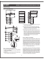
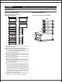
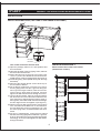
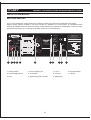
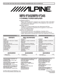
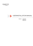
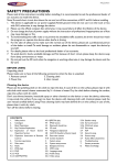
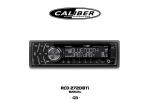
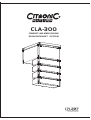
CLA-300
COMPACT LINE ARRAY SOUND
REINFORCEMENT SYSTEM
171.227
USERS MANUAL
EK-YG-MA-070629-001
TABLE OF CONTENTS
Description
1
Acoustic Features
2
Installation
5
Connection
9
Amplification Module
10
Control Software
11
Safety Information
19
Warranty
19
Technical Specifications
20
171.227
COMPACT LINE ARRAY SOUND
REINFORCEMENT SYSTEM
¡
ñCompact design suitable for various application
situations
¡ ñ Up to 40KHz frequency range due to adoption
of ribbon tweeter
¡ ñ Low distortion due to utilization of unique thin
foam surround & specially coated paper cone
¡
ñ Multi-speaker array configurable for flying in
¡
ñ 600W DSP active amplifier
¡
ñ RS232 Port available for system control
different venues, with splay angle adjustable
by 1 increment
DESCRIPTION
the full-range speakers, which forms an integrated
system.
The flying hardware is designed to fit different application
situation flexibly with the splay angel adjustable by
1 increment vertically.
171.227 is specially designed for luxury cinema,
large-sized meeting room, multi-functional hall, church
and auditorium applications. The system consists of
1 active subwoofer and 4 full range speakers which
can form multi-cluster configurations.
171.227 is designed by applying line array concept. It
features compact dimensions and easy to handle design.
The built-in 600W amplifier and DSP make it available
for use at any moment when connected to sound
resource. System control over each cluster at frequency
response, crossover point & slope, delay, gain and
limit protection can be achieved by connecting the
speaker system to PC via RS232 port. Adoption of
ribbon tweeters offers a wide-range frequency response
to up to 40KHz. The tweeter's impedance and phase
response curves are nearly ideal horizontal lines.
The light moving mass of milligrams ensures excellent
impulse response. Utilization of the unique thin foam
surround and specially coated cone paper has reduced
the distortion rate effectively. The active subwoofer
applies Low Distortion, Linear Amplification, and DSP
technologies. Input signals are amplified by the built-in
pre-amplifier, then processed and distributed by DSP,
finally output via power amplifier to the subwoofer and
1
171.227
COMPACT LINE ARRAY SOUND REINFORCEMENT SYSTEM
HORIZONTAL DIRECTIVITY
The data of 171.227 horizontal directivity were collected by testing the speaker system in a big anechoic chamber.
The distance between the testing microphone and the speaker system is 4 meters.
0
0
30
330
60
300
150
210
150
150
4.0kHz
0
30
120
270
150
120
150
210
180
10kHz
60
300
90
270
270
30
330
60
300
90
270
0
30
330
60
300
6.3kHz
180
2.5kHz
0
150
210
180
1.6kHz
180
120
270
150
210
180
90
270
120
270
60
300
90
270
120
270
30
330
60
300
90
270
0
30
330
60
300
210
1kHz
0
30
330
180
630Hz
0
150
210
180
400Hz
210
120
270
150
210
180
90
270
120
270
60
300
90
270
120
270
30
330
60
300
90
270
0
30
330
60
300
330
250Hz
0
30
210
180
160Hz
0
150
210
180
100Hz
330
120
270
150
210
180
90
270
120
270
60
300
90
270
120
270
30
330
60
300
90
270
0
30
330
90
270
120
270
150
210
180
16kHz
The scale is stepped by 6dB increment.
3
171.227
COMPACT LINE ARRAY SOUND REINFORCEMENT SYSTEM
VERTICAL DIRECTIVITY
The data of 171.227 vertical directivity were collected by testing the speaker system in a big anechoic chamber.
The distance between the testing microphone and the speaker system is 4 meters.
0
0
30
330
60
300
150
210
150
150
4.0kHz
0
30
120
270
150
120
150
210
180
10kHz
60
300
90
270
270
30
330
60
300
90
270
0
30
330
60
300
6.3kHz
180
2.5kHz
0
150
210
180
1.6kHz
180
120
270
150
210
180
90
270
120
270
60
300
90
270
120
270
30
330
60
300
90
270
0
30
330
60
300
210
1kHz
0
30
330
180
630Hz
0
150
210
180
400Hz
210
120
270
150
210
180
90
270
120
270
60
300
90
270
120
270
30
330
60
300
90
270
0
30
330
60
300
330
250Hz
0
30
210
180
160Hz
0
150
210
180
100Hz
330
120
270
150
210
180
90
270
120
270
60
300
90
270
120
270
30
330
60
300
90
270
0
30
330
90
270
120
270
150
210
180
16kHz
The scale is stepped by 6dB increment.
4
171.227
COMPACT LINE ARRAY SOUND REINFORCEMENT SYSTEM
INSTALLATION
Ring
Flying Frame
LF
M5 Thumb
Screw
Front Link
MF/HF
M5 Small
Head Screw
Back Link A
LF
Back Link B
MF
Back Link B
5
/HF
Back Link A
171.227
COMPACT LINE ARRAY SOUND REINFORCEMENT SYSTEM
INSTALLATION
INSTALLATION METHOD 1
608
492
437
852
133
900
262
536
250
(4) Demount the two M5 thumb screws at the top of
the front side of MF/HF.
1
(5) Insert the two LF Front Links into the U grooves
along the left & right front edges of MF/HF, make
sure the two screw holes on both sides are aligned,
and tighten the screws through the holes.
(6) Insert one end of the Back Link A into the U groove on the
back of MF/HF and the other end into the U groove on the
bottom of LF, make sure the two screw holes at both ends
of the link are aligned with the corresponding holes in the U
grooves, mount the two M5 thumb screws, and tighten them
(see Figure3). Alignment of the white scale lines on the Back
Link A with the edges of the two U grooves indicates
successful mounting. .
.
2
SPLAY ANGEL ADJUSTMENT
Turn MF/HF speaker together with its Back link Back Link B,
make sure the right scale line marked on the Back Link B
is aligned with the edge of the U groove at the back Of MF/HF
speaker (The numbers marked besides each scale line indicate
different splay angles). Then insert the M5 thumb screw through
the aligned holes of the B ack Link B and the U groove at the
back of the speaker (Alignment with Number 1 hole in the groove
is required when0 /2 /4 /6 /8 /10 of splay angle is
wanted, and alignment with Number 2 hole is required when
3 /5 /7 /9 Of splay angel Is wanted).
3
No.1 Hole
No.2 Hole
4
For example, if the splay angle between two MF/HF
speakers is designed to be 5 , the scale line marked
with the number of 5 on the Back Link B must be aligned
to the bottom edge of the groove on the back of the top
speaker, then a certain hole in the Back Link B will be
found to be aligned with Number 2 hole in the groove at
the back of the top speaker. Insert a M5 thumb screw
through the two aligned holes and tighten it.
ONE CLUSTER FLOWN VERTICALLY
(1) Open the package and take out 171.227 speakers
and the accessories.
(2) Mount the four M8 rings to the flying frame (see
Figure 1).
(3) Demount the two M5 thumb screws at the bottom
Of LF, and take out the Back Link A.
6
171.227
COMPACT LINE ARRAY SOUND REINFORCEMENT SYSTEM
INSTALLATION
INSTALLATION METHOD 2
INSTALLATION METHOD 3
Multi Clusters Flown Vertically
(maximum 4 Clusters)
Cluster stacked with LF at the bottom.
(1) Open the package, and take out 171.227 speakers
and the accessories.
(2) Mount the four M8 rings to the flying frame.
(3) Demount the two M5 thumb screws at the bottom
of LF, and take out the Back Link A. Disassemble
the U grooves and remount the two M5 small head
screws in the original holes.
(4) Disassemble the flying frame of another LF, mount
this LF to the bottom of the first LF by tightening M5
thumb screws accordingly.
(5) Demount the two M5 thumb screws at the top of
the front side of MF/HF.
(6) Insert the two LF Front Links into the U grooves along the
left & right front edges of MF/HF, make sure the two screw
holes on both sides are aligned, and then tighten the
screws through the holes.
(7) Insert one end of the Back Link A into the U groove
on the back of MF/HF and the other end into the U
groove on the bottom of LF, make sure the two
screw holes at both ends of the link are aligned with
the corresponding holes in the U grooves, mount
the two M5 thumb screws, and tighten them (see
Figure3). Alignment of the white scale lines on the
Back Link A with the edges of the two U grooves
indicates successful mounting.
(8) Attach one or more clusters of MF/HF to the
bottom of the installed MF/HF accordingly.
7
171.227
COMPACT LINE ARRAY SOUND REINFORCEMENT SYSTEM
INSTALLATION
INSTALLATION METHOD 4 (THE LONG FLYING FRAME IS OPTIONAL)
1
2
3
5
No.1 Hole
4
No.2 Hole
INSTALLATION METHOD 5
One cluster flown from front to back
(1) Open the package, take out 171.227 speakers and
the accessories.
(2) Open the package of the long flying frame, take out
the frame and accessories.
(3) Mount the M8 rings to the long flying frame (see
Arrow 1), and insert the Back Link B inside the
middle groove of the long flying frame (see Arrow 2).
(4) Put the long flying frame upside down (with the rings
downside).
(5) Demount the two M5 thumb screws at the top of
the front side of MF/HF.
(6) Put the MF/HF upside down. Insert the Front Links of
the long flying frame into the U grooves along the
left & right front edges of MF/HF, make sure the two
screw holes on both sides are aligned, and then
tighten two M5 thumb screws through the holes.
(7) Turn the MF/HF speaker, make the scale line marked
with the number of 0 on the Back Link B attached to the
long flying frame aligned with the bottom edge of
the U groove, then insert a M5 thumb screw through
the two aligned holes and tighten it (see figure 4).
(8) Demount the two M5 thumb screws at the bottom
of LF, and take out the Back Link A. Then demount
the four M5 thumb screws connecting the LF and
the short flying frame, and disassemble the short
frame.
(9) Put the LF upside down, insert the four links on
the back of the long flying frame inside the U grooves
of the LF and make sure the screw holes are aligned
accordingly. Then mount and tighten two M5 screws
through the holes.
Multi clusters flown from front to back
(maximum 4 clusters)
8
171.227
COMPACT LINE ARRAY SOUND REINFORCEMENT SYSTEM
CONNECTION
Signal Input
Power Input
MF/HF Speaker Output
MF/HF Input
MF/HF Output
MF/HF Input
MF/HF Output
MF/HF Input
MF/HF Output
MF/HF Input
9
171.227
COMPACT LINE ARRAY SOUND REINFORCEMENT SYSTEM
AMPLIFICATION MODULE
DSP ACTIVE AMPLIFIER
The LF active amplification module features the integration of DSP and Linear Power Amplification technologies.
With the power capacity of 600W, it can drive a cluster of 5 speakers of 171.227 system. The optimized control
software is available to achieve all-around system control at frequency response & compensation, crossover, delay,
gain and limit protection by connecting the speaker system to PC via RS232 port.
.
CONNECTION:
COMPACT LINE
ARRAY SOUND
REINFORCEMENT SYSTEM
LINE INPUT
AC INPUT
115V 50-60Hz
230V
115V
LINE INPUT
STANDARD CONFIGURATION:
OUT
1 ACTIVE SUB+4F ULL RANGE
Several standard systems can be paralleled
OUT
230V
OUTPUT
230V 50-60Hz
IN
8A MAX
OUT
IN
OUT
IN
OUT
IN
OUT
OUTPUT
System specification:
LINE OUTPUT
CLA-300
OUTPUT
AC OUTPUT
50Hz - 40KHz
FREQ.RESPONSE
(171.227)
115dB/121dB(PEAK)
MAX SPL
300W+300W
H.COVERAGE
ACTIVE SUBWOOFER
120¡
V.COVERAGE
PEAK
No:
300W RMS
HF AMPLIFIER POWER
75WX4 RMS
0.5V
LINE INPUT SENSITIVITY
RS-232
DRIVER QUANTITY
MF/HF:4
LF:8 2
2 + RIBBON DRIVER1
POWER REQUIREMENT
115V/4A 50-60Hz
OR 230V/2A 50-60Hz
DIM(W DH
VOLUME
ã
30¡ - ã 90¡
LF AMPLIFIER POWER
)
4926
NET WEIGHT
089 00mm
45Kg
AC INPUT
1
2
3
4
5
6
7
8
9 10
11
1. Voltage Switch
4. Power Supply Input
7. Line In
10. Signal Indicator
2. Power Supply Switch
5. AC Outputs
8. Line Out
11. Volume
3. Fuse
6. Signal Output (NL4 socket)
9. RS232 Port
10
ã
171.227
COMPACT LINE ARRAY SOUND REINFORCEMENT SYSTEM
SOFTWARE OPERATION INSTRUCTIONS
HOW TO GET THE CONTROL SOFTWARE
The software is burned into the accessory disk which delivered with unit,or you can download it from our web site.
SOFTWARE SETUP
It requires Windows98 or senior operation system, display solution ratio should be over 800*600, at least with
standard RS-232 series interface or one USB interface. The software only include one practical file, you can
run this file.
EQUIPMENTS CONNECTING
Connect the unit with PC computer through RS-232. If PC have no RS-232 connector, but have USB interface,
you can use "RS-232/USB" transferring cable(optional part) to connecting it.
SOFTWARE OPERATION
1> Software display screen as following interface:
Input signal MIC, MUSIC is available for PEQ, LEVEL adjustment. When the LF and LF overlapped, you can
adjust the HPF/LPF, PEQ, LEVEL, Dynamic Range Control and Delay functions perfectly.
System module
Information
REMARKS:
Before unit connected, you can operate the file(open/edit or store), in order to run and operate when connecting
(you can download the data from PC to unit).
11
171.227
COMPACT LINE ARRAY SOUND REINFORCEMENT SYSTEM
SOFTWARE OPERATION INSTRUCTIONS
2> PROGRAM OPERATION MENU
By clicking the correct menu subdirectory, you can adjust the concerned parameters.
You can check present program number, name, edit current program, All information must be under online
situation.
[List Program & Recall]
6 programs list under connecting which stored into unit to select:
12
171.227
COMPACT LINE ARRAY SOUND REINFORCEMENT SYSTEM
SOFTWARE OPERATION INSTRUCTIONS
[Save As Current Program In Device]
Save the parameter you adjusted as a program of
unit, then new program can be used as default data
when turn on unit. See right:
3> ONLINE OPERATION MENU
[Enable Communications]
Click this button, it pop-up the following window:
First option:
Download current program to PC control program, interface display will update at the same
time.
Second option: Upload the PC control program to unit as current program data. When it says connecting or
download is success, PC is online with unit.
[Disable Communications]
Disconnect the PC and speaker unit.
[SerialPort Configuration]
Open Serial port dialog box, select "Connect to
correct PC port connector"
13
171.227
COMPACT LINE ARRAY SOUND REINFORCEMENT SYSTEM
SOFTWARE OPERATION INSTRUCTIONS
4> FILE OPERATION MENU
Open and store PC data to appointed disk directory.
5> FUNCTION MODULE OPERATION
5.1> Input channel parameter configuration (MIC channel for example, LINE channel is same)
5.1.1> MIC input PEG configuration: Use mouse to click the main MIC PEG button into red, display interface:
Type, Frequency, Bandwidth, Level . You can adjust them freely.
14
171.227
COMPACT LINE ARRAY SOUND REINFORCEMENT SYSTEM
SOFTWARE OPERATION INSTRUCTIONS
Choose filter type: Click filter series number, "1" or "2", then click "Type" pull-down menu,it will shows as following
interface. They are: None(No using filter. Direct-pass), Peacking, Bandpass, Hi-shelf, Lo-shelf, Notch 6 filters
types to select.Select correct filter type, then select right frequency, bandwidth and level, finally you can get the
perfect performance.
5.1.2> Gain adjust interface is as following, the volume of MIC can be adjusted by dragging the button
of gain with mouse.
15
171.227
COMPACT LINE ARRAY SOUND REINFORCEMENT SYSTEM
SOFTWARE OPERATION INSTRUCTIONS
5.2> Parameter configuration of output channel(only the HF output channel as a sample, the LF channel is same)
5.2.1> Crossover setting, press the HPF/LPF button, it will be changed to red. The displaying is like the following:
The interface of filter type, BUTTER WORTH,BESSEL.LINKWITZ-RILEY are available for high pass and low pass.
-12dB/Oct36dB/Oct slope is optional, HPF/LPF can be set separately. The interface is as following:
16
171.227
COMPACT LINE ARRAY SOUND REINFORCEMENT SYSTEM
SOFTWARE OPERATION INSTRUCTIONS
5.2.2> PEQ of output setting, press PEQ button of HIGH channel, the following interface will be showed:The setting
method is same as the input channel, there is 6 PEQ available to be adjusted.
5.2.3> Output gain adjust(including phase), press LEVEL button, the gain interface is as following: Dragging the
gain button with mouse can enhance or reduce the channel level, press the phase at the left of gain button
can get the INVERSE or Normal.
17
171.227
COMPACT LINE ARRAY SOUND REINFORCEMENT SYSTEM
SOFTWARE OPERATION INSTRUCTIONS
5.2.4> Dynamic range control
Press DRC button(or COMPRESSSION/LIMIT), the interface is as following:This compression just check the
HF signal, once the signal reach the limit, it will compress the HF and LF synchronously(synchronous action
is for the balance of HF and LF)
Five parameters in the dynamic range table is adjustable(the inner parameter is no name,
not adjustable)
Threshold:
Is the limit value of compression, adjustable from 0dB to -49.5dB
Ratio:
Compression ratio,adjustable from 1:1 to &¡ Þ:1
RMS Estimator Time: The checking time of limit value of compression
Release time:
Release compression time after the checking that the signal level is
under the limit
Attack time:
Start up time after checking that the signal level is above the limit.
5.2.5> The delay setting of output channel
Mainly adjust the distance of sound center to make sure the sound center is same. Press DELAY with mouse,
the 5.2.4 interface will be showed, the right side is the delay adjust range from 0.0208ms to 21.2292ms.
18
171.227
COMPACT LINE ARRAY SOUND REINFORCEMENT SYSTEM
SAFETY INSTRUCTIONS
LIMITED WARRANTY
DO NOT OPEN THE COVER
Do not open the cover to avoid the risk of electric shock
caused by high voltage parts in the product. Any problems
caused by user's wrong actions are out of warranty.
If malfunction occurs during the specified warranty
period from the date of original purchase, the product
will be repaired or replaced without charge .
The Limited Warranty does not apply to:
(a) exterior finish or appearance;
(b) certain specific items described in the individual
product data sheet or owner's manual;
(c) malfunction resulting from use or operation of the
product other than as specified in the individual
product data sheet or owner's manual;
(d) malfunction resulting from misuse or abuse of the
product;
(e) malfunction occurring at any time after repairs have
been made to the product by anyone other than
Manufactory Service or any of its autho rized service
representatives.
DO NOT DAMAGE THE POWER CORD
Please hold the plug when pull out or plug in the cord.
Do not pull out or touch the cord with wet hand, or
it will cause the risk of electric shock. Power supply cords
should be routed so they are not likely to be walked
upon or pinched by items placed on or again st them.
When removing the cord from a power outlet be sure
to remove it by holding the plug attachment and not
By pulling on the cord.
To obtain warranty service, a customer must deliver
proof of purchase of the product in the form of a bill of
sale or receipt invoice.
171.227 Speakers and Speaker Systems are guaranteed
against malfunction due to defects in materials or
workmanship for a period of three (3) years from the
date of original purchase. The Limited Warranty does
not apply to burned voice coils or malfunctions such
as cone and/or coil damage resulting from improperly
designed enclosures. Additional details are included
in the Limited Warranty statement.
AVOID OBJECT AND LIQUID ENTRY
Take care that objects do not fall into and that liquids
are not spilled into the inside of the product.If the object
or liquid enter the product,please ask qualified personnel
to check it.
171.227 Accessories are guaranteed against malfunction
due to defects in materials or workmanship for a period
of one (1) year from the date of original purchase.
Additional details are included in the Limited Warranty
statement.
ABNORMAL STATUS
In the event of abnormal noise and smell, please put
off the power supply and pull out the cord, please ask
qualified personnel to check it.
171.227 Flying Hardware (including enclosure-mounted
hardware and rigging accessories) is guaranteed against
malfunction due to defects in materials or workmanship
for a period of one (1) year from the date of original
purchase. Additional details are included in the Limited
Warranty statement.
NONUSE FOR A LONG TIME
When nonuse it for a long time, please put off the power
supply and pull out the cord to avoid the unexpected
dangers.
Specifications subject to change without notice.
19
171.227
COMPACT LINE ARRAY SOUND REINFORCEMENT SYSTEM
TECHNICAL SPECIFICATIONS
Frequency Range
50Hz - 40KHz
Driver
MF/HF:4
2 + RIBBON DRIVER 1
115dB/121dB( PEAK )
Horizontal Dispersion
Vertical Dispersion
Power Supply
120
1 1 5 V /4 A
300W RMS
Max Constant Power Output For Mid-high Range
75WX4 RMS
2
50 -60 Hz
O R 2 3 0 V/ 2A 50 -6 0Hz
30 - 90
Max Constant Power Output For Mid-low Range
Line In Sensitivity
LF:8
Dimensions (WxDxH)
0.5V
492
536
437
20
608
900mm
45Kg
Gross Weight
50Kg
900
608
492
Net Weight
852
Max SLP
171.227