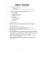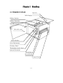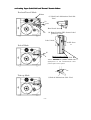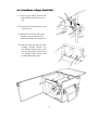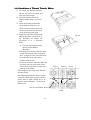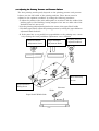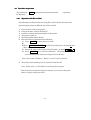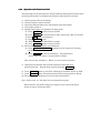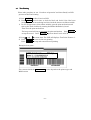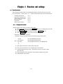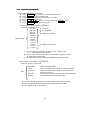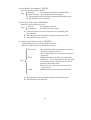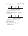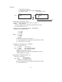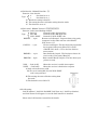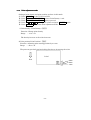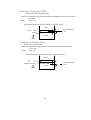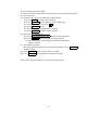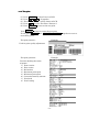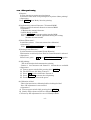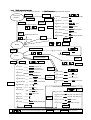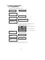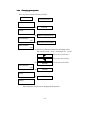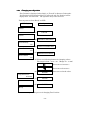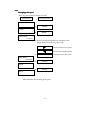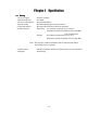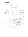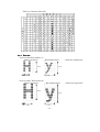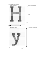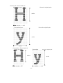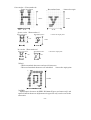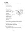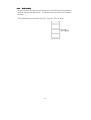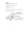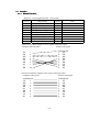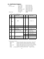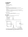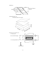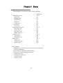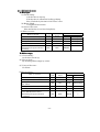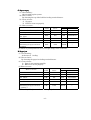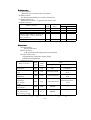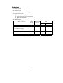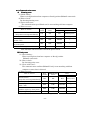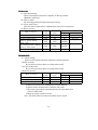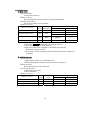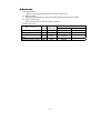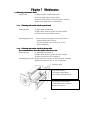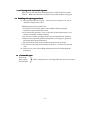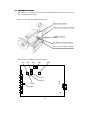
1
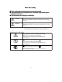
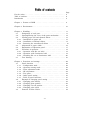
Thermal Printer
RING 8012PMH
Operation Manual
For the safety
Please read trough carefully and use the our product correctly. The listed bellows are very important to use our product safely therefore please
hold by the
the instructions. The denotations and meaning are as followings. Warning
There are possibility of death or serious injury for wrong
operation. Caution
There are possibility of injury physical damage for wrong
operation. * The physical damage represents damage on such as
house hold article, domestic animal and so on.
Example of flow chart symbol :
represents cautions (danger, warning). The contents is indicated inside of
. The character on left represents the caution for
electrification. represents the prohibition. The contents is indicated inside of
.
The character on left represents the prohibition of
decomposition. represents the compulsions. The contents is indicated inside of
. The character on left represents the compulsion of
pull out of power cable. Warning
Please stop the operation in case of noise, smoke, abnormal smell,
or abnormal temperature occurrence. That might cause electrification or fire.
Please turn off the power switch and plug out power cable. Remove
the battery in case of battery type. Never decompose the printer
by yourself. Do not decompose or convert the printer for the repair.
Exclude the case of following manual instruction)
That might cause injury, electrification or fire. Do not use power supply other than specified power supply. That might cause electrification or fire. Do not operate the printer with incursion of foreign material, liquid such
as water, oil, and piece of metal such as clip, pins.
That might cause electrification or fire.
Turn off the power switch immediately and remove the power cable.
Remove battery in case of battery type. Do not use defected power cable.
That might cause electrification or fire.
Please follow the following instruction for handling power cable.
a) Do not locate any object on the power cable.
b) Do not pull, bent or twist the power cable.
Do not convert power cable. Keep heating equipment away from power cable. Do not do star-burst connection nor use auxiliary mains socket outlet
located on back of table tap or PC.
That might cause the electrification or fire. Warning
Do not use power cable other than included power cable.
That might cause the electrification or fire. Please handle the power plug properly. Wrong handling might cause the electrification or fire. Please follow the following instructions for handling power plug.
a) Remove foreign material or dust before plug in.
Plug in all the way to the end. Do not use loose plug socket outlet. Removing power plug. a) Insert or remove the plug by holding plug part. Do not pull
cable part to remove the plug. That might cause the defection
of the cable and cause fire. b) Please unplug the power cable in case of not using for long time.
Unplug the cable with dry hand. Handling of the power cable with
wet hand might cause electrification. Do not unplug the power cable with power switch on. It might cause
deformation of plug or fire. Do not add any impact to power cable as they are made by precision parts.
Turn off the power switch before connecting communication cable or options.
That might cause electrification. Caution
Locate the printer at leveled stable place to avoid the printer to fall down.
That might cause injury.
Locate the printer where children can not reach.
The falling down of the printer might injure the children.
Do not step on the printer or place heavy object on the printer. That might cause some injury by printer to fall down. Please turn off the power switch and check if every connector has
been detached before removing the printer. Do not locate the printer where there are no ventilation.
That might cause fire as heat stays inside of the printer.
Do not locate the printer in following places.
1. Closet or Book shelf.
On carpet or blanket. Do not cover with cloth. Note : The outer case will get high temperature during the operation.
Keep the space of more than 5 cm between the printer and
the surroundings.
Do not place the printer at humid or dusty place.
That might cause electrification or fire. Locate the printer where there is no vibration.
The vibration might cause defection of the printer.
Also, the vibration might cause the printer to fall and cause some
injury. Keep finger away form paper vent part or inside of the printer during
the operation or by the time of power on.
That might cause finger to be caught under the mechanism such as
platen or peel roller. Do not use paper and ribbon other than that are recommended by
us. Using other supplies might cause defection of the printer. Please attention for injury.
Table of contents
For the safety - - - - - - - - - - - - - - - - - - - - - - - - - - - - - - - - Table of contents - - - - - - - - - - - - - - - - - - - - - - - - - - - - - - Introduction
- - - - - - - - - - - - - - - - - - - - - - - - - - - - - - -
Page
2
6
8
Chapter 1 Feature of PMH - - - - - - - - - - - - - - - - - - - - - - - -
9
Chapter 2 Environment - - - - - - - - - - - - - - - - - - - - - - - - - -
10
Chapter 3 Handling - - - - - - - - - - - - - - - - - - - - - - - - - - - - - 11
3-1
: Designation of each part - - - - - - - - - - - - - - - - - - - - - 11
3-2
: Opening/Closing the cover of the print mechanism - - - - - 12
3-3
: Loading paper roll and thermal ribbon - - - - - - - - - - - - 13
3-3-1 : Installation of paper roll - - - - - - - - - - - - - - - - - - - - 13
3-3-2 : Installation of thermal ribbon - - - - - - - - - - - - - - - - - 14
3-3-3 : Removing the wound(used) ribbon - - - - - - - - - - - - - - - 15
3-4
: Adjustment of paper width - - - - - - - - - - - - - - - - - - - - 16
3-5
: Explanation of Operation panel - - - - - - - - - - - - - - - - - 17
3-6
: Procedure of operation - - - - - - - - - - - - - - - - - - - - - - 18
3-6-1 : Operation with Die cut label - - - - - - - - - - - - - - - - - 18
3-6-2 : Operation with Continuous label - - - - - - - - - - - - - - - 19
3-6-3 : Switching Die cut to Continuous label - - - - - - - - - - - - 20
3-7
: Test Printing - - - - - - - - - - - - - - - - - - - - - - - - - - - - 21
Chapter 4 Functions and settings - - - - - - - - - - - - - - - - - - - - - -22
4-1
: Panel functions - - - - - - - - - - - - - - - - - - - - - - - - - - 22
4-1-1 : Configuration mode - - - - - - - - - - - - - - - - - - - - - - - 22
4-1-2 : Operation setting mode - - - - - - - - - - - - - - - - - - - - 24
4-1-3 : Print adjustment mode - - - - - - - - - - - - - - - - - - - - - 29
4-1-4 : HP adjustment - - - - - - - - - - - - - - - - - - - - - - - - - - 32
4-1-5 : Test print - - - - - - - - - - - - - - - - - - - - - - - - - - - - - 34
4-1-6 : Other panel setting - - - - - - - - - - - - - - - - - - - - - - - 35
4-1-7 : Table of panel functions - - - - - - - - - - - - - - - - - - - - 37
4-2
: Example of changing panel setting - - - - - - - - - - - - - - - 38
4-2-1 : Changing print density - - - - - - - - - - - - - - - - - - - - - 38
4-2-2 : Changing print position - - - - - - - - - - - - - - - - - - - - - 39
4-2-3 : Changing tear off position - - - - - - - - - - - - - - - - - - - 40
4-2-4 : Changing print speed - - - - - - - - - - - - - - - - - - - - - 41
4-3
: Function of other switch - - - - - - - - - - - - - - - - - - - - 42
Chapter 5 Specification - - - - - - - - - - - - - - - - - - - - - - - - - - - - 43
5-1
: Rating - - - - - - - - - - - - - - - - - - - - - - - - - - - - - - - - 43
5-2
: Outer dimensions - - - - - - - - - - - - - - - - - - - - - - - - - 44
5-3
: Print mechanism - - - - - - - - - - - - - - - - - - - - - - - - - 45
5-3-1 : Print method - - - - - - - - - - - - - - - - - - - - - - - - - - - 45
5-3-2 : Print head - - - - - - - - - - - - - - - - - - - - - - - - - - - - 45
5-3-3 : Printable character type - - - - - - - - - - - - - - - - - - - - 45
Character code table - - - - - - - - - - - - - - - - - - - - - - 46
5-3-4 : Font size - - - - - - - - - - - - - - - - - - - - - - - - - - - - - 46
5-3-5 : Available barcode - - - - - - - - - - - - - - - - - - - - - - - - 50
5-3-6 : Printing direction - - - - - - - - - - - - - - - - - - - - - - - - 50
5-3-7 : Print speed - - - - - - - - - - - - - - - - - - - - - - - - - - - - 51
5-3-8 : Print area - - - - - - - - - - - - - - - - - - - - - - - - - - - - 51
5-3-9 : Data interface - - - - - - - - - - - - - - - - - - - - - - - - - - 51
5-4
: Functions - - - - - - - - - - - - - - - - - - - - - - - - - - - - - - 52
5-4-1 : Print mode - - - - - - - - - - - - - - - - - - - - - - - - - - - - 52
5-4-2 : Back feeding - - - - - - - - - - - - - - - - - - - - - - - - - - - 53
5-4-3 : Sensors - - - - - - - - - - - - - - - - - - - - - - - - - - - - - - 54
5-5
: Registration of external characters - - - - - - - - - - - - - - - 55
5-6
: Optional function - - - - - - - - - - - - - - - - - - - - - - - - - 55
5-7
: Interface - - - - - - - - - - - - - - - - - - - - - - - - - - - - - - 56
5-7-1 : RS232C interface - - - - - - - - - - - - - - - - - - - - - - - - 56
5-7-2 : RS232C protocol - - - - - - - - - - - - - - - - - - - - - - - - - 57
5-7-3 : Parallel interface - - - - - - - - - - - - - - - - - - - - - - - - 59
5-8
: Papers and ribbons - - - - - - - - - - - - - - - - - - - - - - - - 60
5-8-1 : Paper types - - - - - - - - - - - - - - - - - - - - - - - - - - - 60
5-8-2 : Paper sizes - - - - - - - - - - - - - - - - - - - - - - - - - - - - 60
5-8-3 : Thermal ribbons - - - - - - - - - - - - - - - - - - - - - - - - 62
5-8-4 : Storage of paper and ribbon - - - - - - - - - - - - - - - - - 62
Chapter 6 Errors - - - - - - - - - - - - - - - - - - - - - - - - - - - - - - - 63
6-1
: Error occurrence and error recovery - - - - - - - - - - - - - - 63
6-1-1 : Mechanical related errors - - - - - - - - - - - - - - - - - - - 64
6-1-2 : Communication related errors - - - - - - - - - - - - - - - - - 68
6-1-3 : Analysis related errors - - - - - - - - - - - - - - - - - - - - - 70
6-1-4 : Other errors - - - - - - - - - - - - - - - - - - - - - - - - - - - 71
Chapter 7 Maintenance - - - - - - - - - - - - - - - - - - - - - - - - - - - 73
7-1
: Cleaning and routine check - - - - - - - - - - - - - - - - - - - 73
7-1-1 : Cleaning and routine check on print head - - - - - - - - - 73
7-1-2 : Cleaning and routine check on platen roller - - - - - - - - 73
7-1-3 : Cleaning inside and outside of printer - - - - - - - - - - - 74
7-2
: Handling and replacing print head - - - - - - - - - - - - - - 74
7-3
: Consumable parts - - - - - - - - - - - - - - - - - - - - - - - - 74
7-4
: Adjustment of sensors - - - - - - - - - - - - - - - - - - - - - - - 75
Introduction
Thank you for purchasing a PMH series thermal transfer barcode printer.
Your printer allows you to put an OCR character, barcode, and ordinary
character and graphic character, on an ordinary paper-made label in high quality
by using a thermal transfer ribbon.
Besides, you can also use it as a thermal printer using a thermal paper.
Please read the manual thoroughly to make full use of the capabilities of the
printer and to handle it properly before using your printer.
Keep the manual and the related documents included with the product on hand to
solve your question.
See the reference manual about the program preparation for control over the printer.
Also, we can provide the general-purpose package software that you can make label
from for the models freely and easily.
Package list :
8012PMH thermal transfer barcode printer
Power cable
Operation Manual
Note : A cable for connecting to a host computer is not included.
1
1
1
Chapter 1 Feature of PMH
In addition to the basic print such as alphanumeric characters, graphic characters,
OCR and the like, the printer series have their own characteristics as shown
below.
(1) Since the printer measures label length automatically(in the feed direction)
with label position control, replacement between various kinds of labels in
length does not require troublesome preparation by users.
(2) To cut running costs, the gap between labels is well enough to be 2 mm at
least. (if you use the cutter for label, 4 mm requires at least) To decrease
unprintable area in the cutter, peel off and tear off mode, the printer has
back feed feature.
Label printing having the same format and layout allows continuous print out,
which results in increasing print performance.
(4) An adjustable print density allows a fine tuning for print with good quality.
(5) The ability to adjust the print starting position in fine increments allows fine
adjustment of the printing position.
(6) Easy return from errors (paper empty, paper jamming, no ribbon, print head
open) that occur halfway through printing and the data saving function that
can save data immediately before error occur allow you to continue a normal
operation with the minimum loss time. Chapter 2 Environment
2-1
Please try to install the printer with following conditions.
1. Stable leveled place.
2. Ventilated place.
3. Temperature of 10 to 35 centigrade and humidity of 20 to 80%.
2-2
Please do not install the printer in the conditions below to avoid being
defected as the printer is composed by precision parts.
1. Direct sunlight
2. Grime and dust
3. Rapid temperature change
4. Rapid humidity change
5. Near flame
6. Near water
7. Near volatile material
8. Near air conditioner
9. Near Humidifier
10. Vibrations
2-3
About power supply
1) The voltage range : AC100 to AC260 50/60Hz. ( Switchable power supply)
2) Do not take power from source that might generate noise. (Such as Motor).
2-4
About environment
1) Operating temperature is 5 to 40 centigrade.
Prevent condensation by keeping relative humidity under 85 % RH.
2) Install the printer on leveled place with no vibrations.
3) Do not block the ventilation on of printer. Try to leave the space of at least 5 cm
around the printer.
4) Never do a polishing work using a grinder or a sand paper beside your printer.
The printer hates dusts, especially, such as high hardness dusts, sands, metallic
dust particles, because they might cause the failure of a print head. Pay careful
enough attention to avoid the above dusts. Also, never use your printer in a
dump place or in a dusty place having an oil/iron content dust.
5) Please do not install the printer near TV or radio. The electric wave might
cause some noise to the equipment.
6) In case of using the printer under the condition where electrostatic occurs,
please try to use equipment like “Electrostatic prevention mat” to prevent
the electrostatic.
Chapter 3 Handling
3-1 : Designation of each part
Top Cover
LCD Display
Ribbon Stocker
Ribbon Rewinder
POWER Switch
Left side cover
Label Stocker
Print Mechanism
Printing Head
Mechanism Latch Lever
Internal Rewinder
Peel-off Edge
Peel-off Roller
Control Panel
3-2 Loading Paper (Label) Roll and Thermal Transfer Ribbon
Feed-out/Tear-off Mode
Ribbon
(1) Head Latch Mechanism (Left Side
View)
(1)
Label
Head Latch Lever
(2)
(2) Home Position (HP) Sensor/ Label
guide(Top View)
Label Guide
HP Sens
or
Peel-off Mode
(3)
Label Pressure Plate
HP Sensor Positioning Slide Bar
*When
this
bar
is
pushed
toward
the
right(upward in this illustration),the label
pressure plate can be opened.
Take-up Mode
(3)Peel-off Mechanism (Side View)
3-3-1 Installation of Paper (Label) Roll
(1) Load a paper (label) roll into the
Label Stocker all the way to the
end.
2) To open the Print Mechanism, push
up latch lever.
(3) Thread the end of the paper roll
through a space under the HP
sensor and bring it over the platen.
4) In the peel-off mode, pass the label
backing through between the
peel-off roller and the platen. Also,
see the illustration 2) Peel-off in
3-3 Loading Paper (Label) Roll
for threading of the paper.
3-3-2 Installation of Thermal Transfer Ribbon
1) To remove the Ribbon Rewinder,
lift the left end of the shaft, and
slide it toward the left.
2) Load the ribbon roll into the
Ribbon Stoker all the way to the
end.
3) Open the printing mechanism
by pushing the latch lever up.
Then unroll the ribbon and tread
the end of the ribbon as shown on
as the drawing on the right.
4) Bring the end of the ribbon to the
Ribbon Rewinder and wind it on
the Rewinder by taking the
procedures a) to c) described
below.
a) Pass the end of ribbon under
the bar for the Ribbon
Rewinder.
b) Keeping the a) status, rotate the knob
on the left end of the take-up spool by
90 or 45 degrees in the arrow direction
(2) so that the knob comes into a
collision with the bar.
c) From the b) status rotate the right-side
end of the take-up spool in the arrow
direction (3) a few turns to make sure a
wind-up of the ribbon.
This completes the setup of the thermal
transfer ribbon.
The following illustrations show an axial
view of the ribbon take-up spool , and the
status with its knob rotated 90 or 45
degrees counterclockwise -- in the arrow
direction (2).
Bar for the Ribbon Rewinder
fig. 3-9
Type A
Type B
Knob
Type C
3-3-3 Removing the Wound (Used) Ribbon
a) When the wound ribbon is tied with the Ribbon Stocker, cut the ribbon with a knife
or scissors to free the take-up spool.
b) Remove the Ribbon Rewinder by holding the left end of the spool and lift it while
sliding it toward the right.
c) Return the knob of the Rewinder to its original position as shown in fig. 3-11.
d) Remove the used ribbon from around the Rewinder, and discard it in accordance
with the manner set by the local municipal office of your area.
e) Return the Ribbon Rewinder to its original position by putting the spool in the
groove on the right side of the spool holder, and rotate the spool so that the groove
can catch it.
3-4 Adjusting the Printing Pressure and Pressure Balance
The best printing results partly depends on the printing pressure and pressure
balance over the full width of the printing medium. These factors must be
adjusted to the optimum conditions by taking the following procedures:
a) Adjust the position of the label width guide in accordance with the width of the
printing paper or label backing, leaving margins of 0.5 mm on either side of the
medium (a total of 1 mm or so).
b) Set the printing width adjusting knob to the center of the paper (label) width.
c) For thick paper (label), adjust the printing pressure by turning the paper thickness
adjustment knob clockwise.
d) If the print line is not parallel nor perpendicular to the printing area, correct
it by turning the head parallelism adjustment screw clockwise.
Paper Thickness
Adjustment Knob
Head Parallelism
Adjustment Screw
Printing Pressure
Adjustment Knob
Head Mounting
Screws
Paper Thickness
Fixing Screw
Narrower
Wider
Paper (Label) Width Guide
3-5 Explanation of Operation panel
(1) LCD display :
Displays the status of printer by
16 digits x 2 rows.
Please refer the followings for more details.
(1)
(2) READY/STORE
The green light on in case of “Ready” and blinks
when sending data to memory such as Firmware
up date.
(2)
(4)
(5)
(3)
(3) PAPER DETECT/ERROR
The red light blinks and buzzer sounds in case
(6)
of errors.
(7)
(8) (4) PAUSE
The button to switch “Ready” to “Pause”.
(9)
(11)
(12)
(10)
(5) FEED
The button to feed the paper from “Pause” position.
(6) CALIBRATE LEVEL
The button to execute automatic HP adjust and
paper calibration.
(7) Left arrow
The button to change values and selects mode.
(8) Right arrow
The button to change values and selects mode.
(9) DENSITY/POSITION
The button to adjust printing such as density,
position, cut position.
(10) MENU
The button to chose operation mode such as
speed, print mode, print method.
(11) ENTER
The button to fix or execute the selected functions.
(12) Printer model name :
Contents in box varies depend on the model.
3-6 Procedure of operation
The contents in
LCD display.
represents front panel button and ‘
‘ represents
3-6-1 Operation with Die cut label
The followings are the procedure for using Die cut label for the first time after
purchasing the printer or different size of Die cut label.
1)
2)
3)
4)
5)
6)
Connect power cable to the printer.
Connect interface cable to the host PC.
Load Die cut label and thermal ribbon to the printer.
Turn power switch on.
Check if the LCD shows “Ready”.
Execute HP level adjustment and calibration.
A) Press PAUSE to show ‘Pause’ on LCD.
B)
B) Press CALIBRATE LEVEL to show ‘Learn Gap Level / Sensing 60 mm’.
(Note : 60 mm is default value)
C) Change the value to the length of “Label length + 20 mm) by
D) Press ENTER to execute the calibration. The printer starts feeding
several labels for the calibration and goes back to ‘Ready’.
Note : Please refer “Chapter 6 Errors” in case of error occurrence.
7) The printer starts printing as it receives data from host PC.
Note : Please refer “3-7 Test Print” for executing the test print.
From next time, the printer will goes to ‘Ready’ as you turn on the power
switch as long as using same label.
3-6-2 Operation with Continuous label
The followings are the procedure for using Continuous label for the first time after
purchasing the printer or changing to Continuous label from Die cut label.
1)
2)
3)
4)
5)
Connect power cable to the printer.
Connect interface cable to host PC.
Load only thermal ribbon only and latch the print mechanism.
Turn power switch on.
Change ‘Label Type’ to ‘Continuous’ by front panel.
A) Press PAUSE to show ‘Pause’ on LCD.
B) Press MENU for several times to show ‘Label Type / Die cut’ on LCD.
C) Press
to select ‘Continuous’ .
C) Press ENTER to fix.
D) The LCD shows ‘Set Label Pitch / 53 mm’.
E) Press PAUSE to show ‘Pause’ on LCD.
6) Execute HP level adjustment and calibration.
A) Press CALIBRATE LEVEL and show ‘Learn Gap Level / Sensing
60 mm’.
B) Press ENTER to execute calibration. The LCD shows
‘Learn Gap Level / Busy !!’ and goes back to ‘Ready’.
Note : Please refer “Chapter 6 Errors” in case of error occurrence.
7) Open print mechanism and load the Continuous label and close
print mechanism. Stop the beep sound by pressing PAUSE .
8) Press PAUSE again to clear ‘E01 / Head Open’ and show ‘Pause’ on LCD.
9) Press PAUSE again. The printer feed the label and goes back to ‘Ready’.
10) The printer starts printing as it receives data from host PC.
Note : Please refer “3-7 Test Print” for executing the test print.
From next time, the printer will goes to ‘Ready’ as you turn on the power
switch as long as using same label.
3-6-3 Switching Die cut to Continuous label
The followings are the procedure to change Continuous label into Die cut label.
1) Load Die cut label and thermal ribbon to printer.
2) Turn power switch on.
3) Change ‘Label Type’ from ‘Continuous’ to ‘Die cut’ by front panel.
A) Press PAUSE to show ‘Pause’ on LCD.
B) Press MENU several times to show ‘Label Type / Continuous’ on LCD.
C) Press
to select ‘Label Type / Die cut’.
D) Press ENTER to fix. The LCD will displays ‘Measure Label / Manual’.
E) Press PAUSE to show ‘Pause’ on LCD.
4) Execute HP level adjustment and calibration.
A) Press CALIBRATE LEVEL to show ‘Learn Gap Level / Sensing 60 mm’.
(Note : 60 mm is default value)
B) Change the value to the length of “Label length + 20 mm) by
C) Press ENTER to execute the calibration. The printer start feeding
several labels for the calibration and goes back to ‘Ready’.
Note : Please refer “Chapter 6 Errors” in case of error occurrence.
8) The printer starts printing as it receives data from host PC.
Note : Please refer “3-7 Test Print” for executing the test print.
From next time, the printer will goes to ‘Ready’ as you turn on the power
switch as long as using same label.
3-7 Test Printing
Please take procedure in “3-6 Procedure of operation” and show ‘Ready’ on LCD
previous to the Test Printing.
1) Press PAUSE to show ‘Pause’ on LCD.
2) Press FEED several times to feed the label and check if the label runs
straightly (without meandering) and also check the absence of ribbon wrinkle.
1) In case of appearance of the ribbon wrinkle, open the print mechanism and
take up the slack of ribbon by rotating the Ribbon Rewinder by hand.
Then close the print mechanism.
The beep sound will ring as you open the print mechanism. Press PAUSE
to stop the sound. Press PAUSEagain to show ‘Pause’ on LCD.
4) Press
and
at same time. The LCD will displays ‘Test Print / Pattern 1’.
5) Press ENTER to execute the test printing.
Press PAUSE to stop and restart the test printing.
Example of test print :
The contents inside the
ROM version.
varies depend on the printer type and
Chapter 4 Function and settings
settings
4-1 Panel functions
This chapter describes how to customize the printer’s function for your use with
the panel button. Please refer “4-1-7 Table of panel functions” for list of functions.
Configuration mode
Operation setting mode
Print adjustment mode
HP adjustment
Test print
Other panel setting
4-1-1
4-1-2
4-1-3
4-1-4
4-1-5
4-1-6
4-1-1 Configurat
Configuration
ion mode
Initial setting of the printer is done in this mode.
A) Turn power on while pressing ENTER to show ‘Configuration’ on LCD.
B) Use ENTER and to proceed.
C) Press for selection and press ENTER to fix.
D) Press PAUSE twice to get out from mode.
1) Interface : ‘Interface / ’
Function : Selects interface type for communicating with host PC.
RS
For using RS232C interface.
Parallel
For using parallel interface.
Type
LAN
For using LAN interface (100 BASE-TX).
A) The optional interface can be added only one.
B) Only selected interface can communicate with host PC.
C) Parallel interface in one way. Therefore can not receive the status
from host PC.
D) The settings become valid after exiting from Configuration mode.
E) The default is set as ‘RS’.
2) Command : ‘Command / ’.
Function : Selects command type.
Type
: ALL
Function with standard command.
Please refer ALL command reference manual for the details.
3) Character code : ‘Character Code / ’.
Function : Selects Kanji Code. ( Used only for Japanese market)
4) Home position sensor : ‘HP sensor / ’.
Function : Selects HP sensor type.
Type
:Transmit, Reflect.
A) The sensor type need to be selected for paper type you use.
B) The settings becomes valid after exiting from Configuration mode.
C) The default is set as ‘Transmit’.
5) Count Dictation : ‘Count Dictation / ’.
Function : Selects the way of display for counting.
None
For not displaying counting.
Repeat
For
displaying the count by repeat.
Type
Total
For displaying the count by total.
A) The settings becomes valid after exiting from Configuration mode.
B) The default is set as ‘Repeat’.
6) Feed Speed : ‘Feed Speed / ’.
Function : Selects the speed of feeding.
Range : + 00 to +99
A) The settings becomes valid after exiting from Configuration mode.
B) The default is set as “ +00”.
7) Plane format : ‘Plane format’.
Function : Selects number of drawing memory.
Single
Double
Type
Triple
A) Change only when expanding printing area.
C) The settings becomes valid after exiting from Configuration mode.
D) The default is set as ‘Triple’.
4-1-2 Operation setting mode
Print conditions are set in this mode.
A) Press PAUSE after power on to show ‘Pause’ on LCD.
B) Press MENU to get in to the mode.
C) ‘Print Speed / mm/s’ will be shown on LCD.
D) Press MENU to proceed.
E) Press
keys for selection and press ENTER to fix.
F) Press PAUSE to exit from this mode.
1) Print Speed : ‘Print Speed / mm / s’
Function : Set print speed
300 mm
Available
250 mm
on 4012PSH
200 mm
150 mm
For high speed ribbon
120 mm
100 mm
Speed range
80 mm
60 mm
40 mm
30 mm
For high energy ribbon
20 mm
15 mm
A) The max print speed differs by printer type. Please refer
‘ 5-3-7 Print speed’ for the details.
B) Please select suitable print speed for the ribbon and label you use
to obtain best print quality.
C) The settings becomes valid after exiting from Operation mode.
2) Print Mode : ‘Print Mode / ’.
Function : Selects print mode.
Type
Standard
Strip
Tear off
Peel off
Cut off
Print as feeding labels.
Print as feeding labels. (Stops at cutting position)
Print as feeding labels. (Stops at cutting position
and do not execute
Peel off the label from backing paper after printing.
Cut the label after printing by cutter.
A) Cut off will only be shown in case of installing cutter unit to printer.
B) The settings becomes valid after exiting from Operation mode.
C) The default is set as “Standard”.
3) Print Method : ‘Print Method / ’.
Function : Selects printing method.
Transfer
For printing with thermal transfer ribbon.
Type
Direct Thermal For printing with thermal paper.
A) The settings becomes valid after exiting from Operation mode.
B) The default is set as “Transfer”.
4) Label Type : ‘Label Type / ’.
Function : Selects paper type to use.
Die cut
For using Die cut label.
Type
Continuous
For using continuous label.
A) Continuous label can not be selected in case of printing with
peel off mode.
B) The setting becomes valid after exiting from Operation mode.
C) The default is set as “Die cut”.
6) Measure label : ‘Measure label / ’.
(Only displayed in case of selecting ‘Die cut’ label)
Function : Select the way of calibrating the paper.
Every time
First
Type
PGM
Start calibrating label automatically every time
the power switch is turned on.
It is recommended in case of frequent change of
paper type.
Calibrate the label only when you execute the
calibration. It is recommended to save the label
to avoid unnecessary calibration by the time of
turning on the power switch.
(Please refer “3-6 Procedure of operation” for
more details. )
Handle the label by the data input manually.
A) The settings become valid after exiting from Operation mode.
B) The default is set as ‘Manual’.
6) Set Label Pitch : ‘Set Label Pitch / .mm’.
Function : Sets label length.
Value
: 000.0 ( unit = mm)
Backing paper
Label
Only displayed when
‘PGM’ or ‘Continuous’ is
selected.
Label
Feed
Label length( Label length + Gap length)
A) This mode is displayed only when ‘PGM’ is selected at ‘Measure Label’.
B) The settings become valid after exiting from the mode.
C) The default is set as 053.0 mm.
7) Set Gap Length : ‘Set Gap Length / .mm’.
Function : Sets Gap length.
Value : 000.0 (unit = mm)
Backing paper
Label
Only displayed when
‘PGM’ or ‘Continuous’ is
selected.
Label
Feed
Gap lengthThe gap between labels
A) This mode is displayed only when ‘PGM’ is selected at ‘Measure label’.
B) The settings become valid after exiting from the mode.
C) The default is set as 003.0 mm.
8) Left margin : ‘Left Margin’ / ’.
Function : Creates space on left side for the printing.
Range : 0 to total element amount – 1 (dot)
A) The print out shift to the right as increasing the value.
B) The setting become valid after exiting from the mode.
C) The default is set as 0000.
Example :
* The origin of print out.
The origin of label ( Left edge of print head)
Left Margin = 0000
Left Margin = 0050
X=0
X= 0 X= 50
Y=0
ABC Y=0
Feed
The origin shifts to the right for 50 dots.
9) Label Skip : ‘Label Skip / ’.
Function : Select how many label absence to ignore.
Range
: 00 to 10 labels
A) The setting becomes valid after exiting from the mode.
B) The default is set as 01.
10) RS baud rate : ‘RS232C Baud Rate / ’.
Function : Sets the baud rate.
115.2K
57.6K
38.4K
Range
19.2K
9600
4800
A) Match the baud rate to host PC.
The setting becomes valid after exiting from the mode. C) The default is set as 9600.
11) RS parity : ‘RS232C Parity / ’.
Function : Sets parity bit.
None
For no parity
Type
Even
For even parity setting
Odd
For odd parity setting
A) Match the setting to host PC.
B)The setting become valid after exiting from the mode.
C)The default is set ‘None’.
12) RS Stop bit : ‘RS232C Stop Bit / ’.
Function : sets stop bit.
1.
Sets stop bit to 1.
Type
2.
Sets stop bit to 2.
A) Match the setting to host PC.
B) The setting becomes valid after exiting from the mode.
C) The default is set ‘1’.
13) RS data bit : ‘RS232C Data Bit / ’.
Function : Sets data bit.
8
Sets data bit as 8.
Type
7
Sets data bit as 7.
A) Match the setting to host PC.
B) The setting becomes valid after exiting from the mode.
C) The default is set as ‘8’.
14) RS control : ‘RS232C Control / ’.
Function : Select hand shaking method.
RS / CS
Controls by RS / CS signal line.
Type
ER / DR
Controls by ER / DR signal line.
XON / XOFF
Controls by XON / XOFF code.
RS(RTS) - - - 8 pin
Return to send(output). : Requests data to the parity
(computer) on the other end line with “SPACE”
(ON, about + 7V).
CS(CTS) - - - 7 pin
Clear to send(input) : The line shows the preparation
for reception of the parity. (Host PC) is ready.
“SPACE” (ON, about + 7V) on the line allows to
return status.
DR(DSR) - - - 4 pin
Data Set Ready (input) : The line shows data to be
sent is ready in the parity (Host PC).
ER(DTR)- - - 6 pin
Data terminal Ready (output) : The line shows your
printer is ready.
XON - - - Code (11H)
Shows the receiver is enable for reception.
XOFF - - - Code(13H)
Shows the receiver is disable for reception.
A) Only selected becomes valid. Ex) In case of setting RS / CS, the XON / XOFF
Connecter
code is not generated.
B) The settings become valid after exiting from
the mode.
C) The default is set as ‘RS / CS’.
Fig.4-1d
15) LAN setting :
‘LAN IP Address’, ‘LAN Sub Net MSK’, LAN Gate way’, ‘LAN Port Number’,
and ‘LAN Protocol’ will appear in case the LAN interface is installed.
Please refer LAN interface manual for the details.
4-1-3 Print adjustment mode
Setting of print density and print position are done in this mode.
A) Press PAUSE to show ‘Pause’ on LCD.
B) Press DENSITY / POSITION to show ‘Print Density / +-00’.
C) Press DENSITY / POSITION again to proceed.
D) Press
to change the values and press ENTER to fix.
E) Press PAUSE to exit from Print adjustment mode.
1) Print density ‘ Print Density / ’
Function : Change print density.
Range : - 15 to + 15
The density increase as the value increases.
2) Print position ‘Print Position / ’
Function : Adjusting print starting position by 0.1 mm.
Range : - 30 to + 30
The print out goes back against feeding direction as increasing the value.
Label
Feed
3mm
2mm
1mm
(3) Tear position ‘ Tear Position / ’
Displayed in Tear off / Strip mode.
Function : Adjusts the stop position of label after printing in Tear off / Strip mode
by 0.1 mm.
Range
: - 30 to + 30
The position goes back against feeding as value increases.
Label
Gap
2 mm
Label
Tear off position
00
Feed
Peel position ‘Peel Position / ’
Displayed in Peel off mode.
Function : Adjusts the stop position of label after printing in Peel off mode
by 0.1 mm.
Range : - 30 to + 30
The position goes back against feeding as value increases.
Label
Gap
Standard 2 mm
Label
Feed
Peel off position
00
Cut position ‘Cut Position / ’
Displayed in Cut off mode.
Function : Adjusts the stop position of label after printing in Cut off mode
by 0.1 mm.
Range : - 30 to + 30
The position goes back against feeding as value increases.
Label
Gap
Standard 2 mm
Label
Cut position
00
Fig.4-1h
Feed
(4) Engulf defense ‘Engulf Defense / .
Displayed in Tear off / Cut off mode.
Function : Adjusts waiting position of label after printing in Tear off / Cut off
mode by 0.1 mm.
Range 0 to 99.9 mm.
A) The position goes back against feeding as value increases.
B) Press and to change values and
press FEED to shift digit.
C) Press ENTER to fix.
Label
Feed
Platen
Label waiting position
Tear off / Cut off position
5.0 mm(Standard)
Label
The default is set as 5.0 mm.
4-1-4 HP adjustment
This printer has function of automatic HP sensor adjustment.
The learned adjustment is registered in printer therefore not necessary to
make the adjustment as long as using same paper.
Note : Please make sure to do HP sensor adjustment in case of changing
paper.
Procedures :
In case of using Die Cut label.
(1) Load label and ribbon and turn on power switch to show ‘Ready’ on LCD.
(2) Select ‘Label Type’ to ‘Die Cut’.
A) Press PAUSE to show ‘Pause’ on LCD.
B) Press MENU several times to show ‘Label Type ‘.
C) Select ‘Die cut’ by using
.
D) Press ENTER to fix.
E) Press PAUSE to show ‘Pause’ on LCD.
(3) Executing HP adjustment.
A) Press PAUSE and show ‘Pause’ on LCD.
B) Press CALIBRATE LEVEL to show ‘Learn Gap Level / 060 mm’.
( The default is 60 mm)
C) Set the value to length of “Label length + 20 mm” by using
D) Press ENTER to execute the HP level adjustment.
E) The LCD shows ‘Learn Gap Level / BUSY !!’ and feed labels.
The printer starts calibration of the label successively in case
the ‘Measure Label’ mode is set as ‘Every’ or ‘Manual’.
The LCD shows ‘Measure Label / Busy !!’ and feed several labels.
F) LCD shows ‘Ready’ as completing HP adjustment.
Please refer “Chapter 6 Errors” in case of error appearance.
.
In case of using Continuous label.
(1) Load only thermal ribbon(Do not load paper) and close print mechanism.
(2) Turn power on.
(3) Change ‘Label Type’ to ‘Continuous’ by front panel.
A) Press PAUSE to show ‘Pause’ on LCD.
B) Press MENU several times to show ‘’Label Type’.
C) Select ‘Continuous’ by using
.
D) Press ENTER to fix.
E) The LCD shows ‘Set Label Pitch / 53 mm’.
F) Press PAUSE to show ‘Pause’ on LCD.
(4) Executing HP adjustment.
A) Press CALIBRATE LEVEL to show ‘Learn Gap Level ‘.
B) Press ENTER to execute HP level adjustment.
G) The LCD shows ‘Learn Gap Level / BUSY !!’ and shows
‘Ready’ on LCD.
(5) Load label to printer.
The beep sound will ring as opening head mechanism. Press PAUSE to
stop the sound.
(5) Press PAUSE again to show ‘Pause’ on LCD.
(6) Press PAUSE once again to show ‘Ready’ on LCD.
Please refer “Chapter 6 Errors” in case of error appearance.
4-1-5 Test print
(1)
(2)
(3)
(4)
(5)
Press PAUSE to show ‘Pause’ on LCD.
Press
all together.
‘Test Print / Pattern 1’ will be shown on LCD.
Press to select ‘Test Print / Pattern 2’ .
Press ENTER to execute the test print.
Press PAUSE to stop or restart the test print.
To exit, press ENTER and DENSITY / POSITION together to reset or
turn off the power.
Test print pattern 1 :
Example
Used for print quality adjustment.
Test print pattern 2 :
Example
Used for checking the status
of printer.
1) Farm version
2) Font version
3) Mechanism
4) Maximum print speed
5) Minimum print speed
6) Generation memory amount
7) Print head
8) Panel setting
4-1-6 Other panel setting
1) Reprint :
It is the function to reprint previous format.
It functions when there is no printing data in printer. (After printing)
< Operation >
Press FEED from ‘Ready’ after the printing.
2) Implementing external character ( To internal ROM)
Writing registered external character to internal ROM.
< Operation >
a) Register the external character.
b) Show ‘Ready’ on LCD.
c) Press ENTER a to execute writing into the ROM.
Note : The ‘READY / STORE” light blinks during the writing.
(It takes 10 to 20 seconds)
3) Reset (Warm start) :
It initializes printer. ( Does not execute the calibration)
< Operation >
Press DENSITY / POSITION and ENTER together.
4) Resting ‘Count Dictation’ :
It is the function to reset (00000) ‘Count Dictation’.
This function is valid only when ‘Total’ in ‘Count Dictation’ is selected.
< Operation >
From ‘Pause’, press
and DENSITY / POSITION together.
5) Self printing :
This is the function for demonstration printing.
‘Pattern 1’ for Characters and ‘Pattern 2’ for Barcode are available.
< Operation >
A) Turn on power switch while pressing down PAUSE .
B) The LCD shows ‘Self Print / Pattern 1’.
C) Press
to select ‘Self Print / Pattern 2’.
D) Press ENTER to execute the self printing.
E) To exit, try reset or turn of the power.
6) Calibration of label:
This is the function for calibrating label as feeding the label.
Note : HP adjustment is not executed.
< Operation >
A) Turn on power switch while pressing down FEED .
B) ‘Ready’ will be shown on LCD as calibration completes.
C) Please try ‘HP adjustment’ in case of ‘ HP Adjust Error’.
7) Label positioning :
This is the function to adjust the label position to print starting position.
< Operation >
A) Turn on power switch while pressing
.
C) ‘Ready’ will be shown on LCD as completing.
4-1-7 Table of panel functions
Please refer 4-1-1 to 4-1-6 for the details The Bold character represents the default.
ENTER
Power on
ENTER
Configuration
initialize
PAUSE
PAUSE
PAUSE
ENTER
Self Print Pattern 1 Execute
Self Print Patten 2 Execute
FEED
MENU
Calibration( Die cut)
FEED
Positioning
Reprint
Interface
Command
Character code
HP sensor
Count Dictation Feed speed
Plane Format
ALL
Shift JIS,
JIS JIS
Trans,
Trans, Reflect
Repeat,
Repeat, Total, None
+00to
+00 + 09
Triple,
Triple Single, Double
ENTER
Ready
RS
RS Para, LAN, USB
ENTER
CALIBRATE LEVEL
PAUSE
Sensing 060
060 mm
Learn Gap level
ENTER
Execution
Pause
DENSITY/POSITION
MENU
PAUSE
ENTER
Self Print Pattern 1Execute
FEED
Print speed15 to 300(mm/sec.)
Print mode
Standard,
Standard Strip, Tear off,
Peel off, Cut off, Applicator
Print Method
Transfer,
Transfer Direct Thermal
Label type
Die cut,
cut Continuous
Measure Label
Every, Manual,
Manual PGM
Set Label Pitch
003.0 to 053.0 to 999.9 (mm)
Set Gap Length
001.0 to 003.0 to 999.9 (mm)
MENU
ENTER
Self Print Pattern 2Execute
PAUSE
Print density
- 15 to 00 to + 15
Print position
- 30 to 00 to +30
Tear position
- 30 to 00 to + 30
Engulf Defense 00.0 to 05.0 to 99.9 (mm)
DENSITY
POSITION
ENTER
Left Margin
- 30 to 00 to + 30
Displayed when LAN I/F (Option) is attached.
Label Skip 00 to 01 to 10
FEE
RS baud rate
4800, 9600,
9600 19200, 38400,
LAN IP address
57600, 115200
RS parity None,
None Even, Odd
LAN Sub Net MSK
RS stop bit 1, 2
LAN Gate way
MENU
RS data bit 8, 7
00000 to 65535
LAN Port Number
RS control RS/CS, ER/DR, XON/XOFF
FTP,
LAN Protocol
FTP Socket through
ENTER
ENTER
: Selecting items and changing values, FEED
: Shift digit, ENTER
: Fix ( Register)
4-2 Example of changing panel setting
4-2-1 Changing print density
Turn power on and show ‘Ready’ on LCD.
LCD display
Panel operation
Ready
(1)
PAUSE
Pause
(2)
DENSITY/POSITION
Print Density
+00
(3) Please use following button to change values.
The range is from – 15 to + 15.
(4)
Press once to increase 1. Press once to decrease 1.
ENTER
Press once to fix the value.
Print Position
+00
(5)
PAUSE
(6)
PAUSE
Pause
Ready
This completes the process of changing print density.
-38-
4-2-2 Changing print position
Turn on power and show ‘Ready’ on LCD.
LCD display
Panel operation
Reday
PAUSE
(1)
Pause
(2)
DENSITY/POSITION
(3)
DENSITY/POSITION
Print Density
+00
Print Position
+00
(4) Please use followng buttons for changing values.
The range is from – 30 to + 30 ( Range of + - 3 mm)
Press once to increase 1. Press once to decrease 1.
(5) ENTER
Press once to fix value.
Print Density
+00
(6)
PAUSE
(7)
PAUSE
Pause
Ready
This completes the process of changing Print position.
4-2-3 Changing tear off position
‘Tear Position’ is displayed when ‘Strip’, or ‘Tear off’ is chosen as Print mode.
‘Peel Position’ will be displayed for ‘Peel off’ mode and ‘Cut Position’ will be
displayed for ‘Cut off’ mode. The operation stays same however.
Turn on power to show ‘Ready’ on LCD.
LCD display
Panel operation
Ready
(1)
PAUSE Pause
(2) DENSITY/POSITION
Print Density
+00
(3)
DENSITY/POSITION
Print Position
+00
(4) DENSITY/POSITION
Tear Position
+00
(5) Please use following buttons for changing values.
The range is from – 30 to + 30. (Range of + - 3 mm)
Press once to increase 1. Press once to decrease 1.
(6) ENTER
Engulf Defense
05.0 mm
(7)
PAUSE
(8)
PAUSE Press once to fix the value.
Pause
Ready
This completes the process of changing Tear Position.
4-2-4
Changing print speed
Turn on power and show ‘Ready’ on LCD.
LCD display
Panel operation
Ready
(1)
PAUSE
(2)
MENU
Pause Print Speed
***mm /s
(3) Please use following buttons for changing value.
Range differes depends on printer type.
Press to select lower speed.
Press to select higher speed.
(4)
ENTER
(5)
PAUSE
(6)
PAUSE
Print Mode
Standard
Pause
Ready
This completes the changing print speed.
Press once to fix the value.
4-3 Function of other switch
There are three DIP switch on main board. They are named as DS1, DS2 and DS3.
DS1 and DS2 are for internal setting of the printer therefore must not be changed.
1) Explanation of function for DS3
Switch function
Switch
Function
No.
ON
OFF
1
LCD display
English
Japanese
2
3
4
5
6
7
8
Factory setting
Over seas Domestic
ON
OFF
Chapter 5 Specifi
Specification
cation
5-1 Rating
1) Power supply
2) Rated frequency
3) Power consumption
4) Print media
5) Thermal ribbon
6) Environment
AC100V to 260V
50 / 60Hz
About 340VA (Max)
Recommended paper form by Autonics.
Recommended thermal ribbon by Autonics.
Operating :An ambient temperature of 5 to 40.
Maximum relative humidity of below 85%RH.
(No condensation)
Storage
:An ambient temperature of 0 to 70
Maximum relative humidity of below 90%RH.
Note : The storage condition of Media (Label) and thermal ribbon
should kept same as printer.
7) Dimensions
8) Weight
365(W) x 335(H) x 430(D) mm (Protrusions are not included)
About 23 kg
5-2 Outer dimensions
5-3 Print mechanism
5-3-1 Print method
(1) Thermal transfer printing :Use of thermal transfer ribbon
(2) Thermal printing :Use of thermal paper
5-3-2 Print head
1) Maximum printable width : 219.5 mm +- 0.2 mm
Composition of thermal elements : 2592 dots in one line.
Dot density : 11.8 dots / 1 mm in width and feeding direction.
2) Arrangement of Heater elements :
84.7m
84.7 m
5-3-3 Printable character
character type
Alphanumeric characters, Kana, Symbol(Defined by JIS C6220), Graphics.
For characters, please refer Table 5-1.
Character size are as followings.
1) 16 x 16
:Dot matrix
2) 16 x 24
:Dot matrix
3) 48 x 60
: Dot matrix
4) 32 x 40
: Dot matrix
5) 24 x 36
: Dot matrix
6) 24 x 24
: Dot matrix
7) 12 x 12
: Dot matrix
8) 8 x 8
: Dot matrix
Table 5-1 Character code table
5-3-4 Font size
a) 16 x 16 dots (Font number 1)
Upper case lettersDescendant letters* shows the origin point.
14 dot
16 dot
1 dot 9 dot 16 dot
b) 16 x 24 dots ( Font number 2)
Upper case lettersDescendant letters
20 dot
24 dot
1 dot 13 dot
16 dot
* shows the origin point
C) 48 x 60 dot (Font number 3)
Upper case letters
3 dot
51 dot
34 dot
Descendant letters
* shows the origin point
60 dot
* shows the origin point
48 dot
d) 32 x 40 dot (Font number 4)
Upper case letters
4 dot
Descendant letter
*shows the original point
40 dot
32 dot
e) 24 x 36 dot (Font number 5)
Upper case letter
28
dot
32 dot
23 dot
* shows the original point
Descendant
shows the original point
1 dot 21 dot
24 dot
36 dot
f) 24 x 24 dot ( Font number 6)
Upper case letter
Descendant letter
20 dot
2 dot
24 dot
16 dot
g) 12 x 12 dot (Font number 7)
Upper case letter
Descendant letter
12 dot
9 dot
9 dot
h) 8 x8 dot (Font number 8)
Upper case letter
7 dot
* shows the origin point.
12 dot Descendant letter
7 dot 8
* shows the origin
24 dot
* shows the origin point.
dot
8 dot
i) Kanji
JIS first standard characters and special characters
JIS second standard characters are embedded. * shows the origin point.
24 dot
24 dot
j) OCR B
Alphanumeric character of SIZE I JIS C6250 (Upper case letters only), and
optional OCR A characters (alphanumeric uppercase only) can be used as the
alternative.
K) External character
24 x 24 dot matrix character
340 characters
About 2 mm x 2 mm (Only character)
* The data is erased by turning off the power switch as there is not back up
by battery.
It is necessary to implement the data to internal ROM to save the data.
Please refer “4-1-6 Implementing external character” for the details.
l) Character magnification
Width 1 to 10, and 16 times.
Height 1 to 10, and 16 times.
!"#$%$%
5-3-5 Available barcode
a) CODE 39
b) NW7 (CODABAR)
c) JAN 13 / 8
d) JAN 13 / 8 with human readable
e) EAN 13 / 8
g) 2 of 5 (Interleaved, Industrial)
h) CODE 93
i) CODE 128
j) PDF417
k) QR Code
l) Veri Code
m) Data Code
5-3-6 Printing direction
Setting moves in a clockwise direction.
0, 90, 180, 270 degrees
Please refer “ALL command reference manual” for the details.
0
90
180
270
Character
Barcode
: Arrow represents feed direction
* represents the position of start code.
5-3-7 Print speed
1”-6” / sec. (15 mm to 150 mm / sec.)
5-3-8 Print area
8.6” x 25.5” (219 x 650 mm)
55-3-9 Data interface
(1) RE232C interface (Compliance)
a) Data transfer speed (bps)
4800, 9600, 19200, 38400, 57600, 115200
b) Data configuration
Data
Parity
Stop bit
c) Transfer method
Half-duplex channel
(2) Parallel interface
a) Data configuration
b) Control signal
8 bit parallel
No paper
BUSY
ACK
FAULT
SELECT
7 bit / 8 bit
Presence / Absence, Even / Odd
1/2
5-4 Functions
5-4-1 Print mode
The printer has the following ways (mode) to handle paper after printing.
1) Standard mode :
Prints label for specified
numbers and stops just at the
end of print out.
2) Strip mode :
Prints label for specified
numbers and stops at
cutting position. The printer
starts printing with back
feeding the label to print
from top position.
3) Tear off mode :
Prints label for specified
numbers and stops at
cutting position. The printer
starts printing with back
feeding the label to print
from top position.
The difference from Strip
mode is that printer does not
accept next data until tearing
print label off.
4) Peel off mode :
The label is automatically peeled off from backing paper after the printing.
The printer starts printing with back feeding the label to print from top position.
5) Backing paper rewinding ( The factory option)
This is option to rewind backing paper to optional Rewinder.
This is used for the label that is difficult to peel off.
This is option that function under “Peel off mode”.
6) Cut off mode : (The factory option)
The label is cut by the cutter unit that is attached in front of the printer after
printing. The label can be cut by either each label or specified number
of labels.
5-4-2 Back feeding
In general, about 10 to 25 mm unprintable area occurs between the print head
element and the tear off position. To eliminate the loss, printer has back feed
function.
The back feeding is activated in “Peel off”, “Tear off”, “Cut off” mode.
5-4-3 Sensors
(1) Home Position sensor (HP sensor)
This is a sensor to detect control the paper. (Label)
(2) Ribbon sensor :
This is a sensor to detect ribbon break and empty.
(3) Head latch sensor :
This is a sensor to detect head closed.
(4) Label sensor :
This is a sensor to detect existence of paper(label) in “Peel off” or “Tear off” mode.
Sensors in the Printing Head Mechanism
Head Latch Sensor
Label Sensor (light receiving)
Ribbon Sensor
HP (Home Position) Sensor
Label Sensor (light emitting)
5-5 Registration of external character
Number of external character : 340 characters
Character size
: 24 x 24 dot matrix character
About 2 mm x 2 mm(Only characters)
* The data will be erased by turning off the power switch as there is not back up
by battery.
It is necessary to implement the data to internal ROM to save the data.
Please refer “4-1-6 Implementing external character for the details.
5-6 Optional function
(1) Other size character font, Gothic Kanji(32 x 32)
(2) OCR A character ( JIS C6250) Alpha numeric character (Upper case letters only)
(3) Auto cutter
(4) Reflective sensor : Controls paper(Label) by the mark on the paper instead of gap.
5-7 Interface
5-7-1 RS232C interface
Table 5-2 Pin assignment table ( Pin insert)
Pin No.
Signal name
NC
SD ( Send data)
RD (Receive data)
DR ( Data set ready)
SG ( Signal ground)
ER ( Data terminal ready)
CS ( Send ready)
RS ( Send request)
NC
1
2
3
4
5
6
7
8
9
In/out
Note
Out
In
In
Out
In
Out
Connection to Host computer ( 25 to 9 pins connection cable)
Computer side (25 pins)
Printer side (9 pin)
FG
SD
RD
RS
CS
DR
SG
----ER
GND(Shield)
1 NC
2 SD
3 RD
4 DR
5 SG
6 ER
7 CS
8 RS
9 NC
1
2
3
4
5
6
7
20
Connection to Host computer ( 9 to 9 pin connection cable)
Computer side (9 pin)
Printer side (9 pin)
GND(Shield)
CD
1
RD
2
SD
3
ER
4
SG
5
DR
6
RS 7
CS 8
RI 9
GND(Shield)
1 NC
2 SD
3 RD
4 DR
5 SG
6 ER
7 CS
8 RS
9 NC
Computer side
RS(Out )
Brief transmit / receive timing
Printer side
ON
CS(In)
OFF
CS(In)
ON
RS(Out)
OFF
SD(Out)
RD(In)
Data
RD(In)
Status
Printer operation
Image creation
SD(Out)
Print operation
Time
5-7-2 RS232C protocol
(1) Initialization ( After power on)
Printer
: Turn on RS/ER line to wait for receiving data.
Computer
: Turn on RS/ER line to set ready for sending data.
(2) Data sending and printing
Prepare image based on data from the computer to perform printing.
The printer cannot receive data from computer during printing.
When RS line of the printer is off, the printer cannot receive data.
(3) Sending the status to computer
1) When required by host computer :
Do not make a status request immediately after the computer sends print
data. This is because the printer needs to receive print completion signal
previous to status request. The printer also permits the error status
request after the error occurrence. After resetting the error, the status
is transmitted to the computer.
2) Error occurrence :
The ribbon , paper, or paper jamming error is sent to the computer after
printing for one sheet of paper is completed.
3) When errors are recovered :
4) When printing in print area is completed :
Please note that the print head is not positioned at the starting position
of printing. Do not send data while RS line of the printer is off (About
-7V) even though it seems that the printer make a request for next data.
Note : RS of the host computer should be always kept ON. (About +7V on
RS line.)
The status transfer from the printer can happen at any moment. If the
computer ignores the status of errors, or the transfer condition of the
printer is set to be OFF, the status cannot be transferred correctly.
Check the following two lines from printer to host computer.
1) RS line of the computer is at the ON state. (CS of the printer is ON)
2) ER line of the computer is at the ON state. (DR of the printer is ON)
If both 1) and 2) lines are ON at the same time, the status can be
transferred correctly.
If either of two lines is the off state, the status is not transferred correctly.
If you don’t need the status, you don’t think about the above condition.
If your computer needs status signal with either line to be off, the printer
enters into the standby status for data input while the computer is
waiting for the status, which may result in stopping in operation.
5-7-3 Parallel interface ( Compliance )
(1) Data
8 bit parallel
(2) Control signal
Paper empty
BUSY signal
ACK signal
Printer error signal
Select signal
Strobe signal
(3)Connector
57-40360
Positive logic input
Positive logic output
Positive logic output
Negative logic output
Negative logic output
Positive logic output
Negative logic input
(DDK)
Table 7-2 Pin Assignments
Pin
Input/
No.
Output
1
2
3
4
5
6
7
8
9
10
11
Input
Output
Output
12
Output
13
Output
Input
Signal name
STROBE (Negative logic)
D0
D1
D2
D3
DATA
D4
D5
D6
D7
ACK (Negative logic)
BUSY (Positive logic)
Paper empty
(Positive logic)
Select (Positive logic)
Pin
Input/
No.
Output
19
20
21
22
23
24
25
26
27
28
29
STROBE 0V
D0
D1
D2
D3 DATA 0V
D4
D5
D6
D7
ACK 0V
BUSY 0V
30
Paper empty 0V
31
32
14
15
16
NC
17
Frame ground (0V)
18
Pull up to 5V at 22 ohm.
Signal name
33
34
35
36
Input
Printer reset
(Negative logic)
Print error
(Negative logic)
0V
NC
Pull up to 5V at 5.1k
ohm.
NC
Signal level is TTL level
(4) Description of signals :
Paper empty
: Outputs with positive logic at “Paper empty”, “Paper jam”.
BUSY
: Outputs with positive logic during the data processing.
ACK
: Negative logic signal by the time of data input completion.
Printer error
: Outputs with negative logic by the time of error occurrence.
Select
: Outputs with positive logic when power is turned on.
Strobe
: A timing signal for synchronization for data. Negative logic 1.
5-8 Papers and ribbons
55-8-1 Paper types
(1) Paper type
a) Roll type die cut paper
b) Roll type continuous paper
c) Fan fold paper
(2) Paper Type
Please contact us for selecting paper type as there are various kinds of
combination of paper type and thermal ribbons.
Before you choose the paper type, be sure to check thermal transfer performance
in advance.
If you can choose our standard paper, you can use it in an easier and more
carefree manner. Print quality depends on paper type. Generally, use a paper
with high surface smoothness.
(3) Paper thickness
0.065 to 0.27 mm. ( Includes backing paper)
In case of selecting thick paper, select the one as soft as possible.
55-8-2 Paper size
(1) Paper width (Includes backing paper) and minimum length.
Width :
40 mm to 116 mm
Minimum length :
a) Standard mode
5 mm
b) Peel off mode
25 mm
c) Tear off mode
35 mm
d) Cut off mode
35 mm
Note : Please contact us in case of using shorter length than specified above.
(2) Minimum gap size.
Feed direction
Minimum gap width
Note : Minimum gap length of 4 mm is needed for using with “Cut off”
off” mode.
(3) Roll size
Paper Maximum diameter
75mm 220 mm
MAX.228 mm
(4) Fan fold paper size
( Fan fold stocker is an option)
(5) Paper size and print area
A : Label pitch
B : Actual label length
Printable area
C : Actual printable area
Feed direction
(6) Label position in “Peel off” mode.
At the “Peel off” mode, the distance from
the right edge of the label to the right edge of
the backing paper must be within 4 mm
because of limitation by the installed position
of label sensor.
4 mm or less
5-8-3 Thermal ribbon
Thermal ribbon have much influence for not only print quality but also life of
print head. It is recommended to use our genuine ribbons.
Also, the warranty does not cover any ribbons except our genuine ribbons.
(1) Ribbon thickness
(2) Base material
(3) Ink color
(4) Ink
(5) Length
(6) Width
6 m / 4.5 m
Polyester film
Black
Wax, Resin, and mixture of Wax and Resin.
300 m / 330 m / 450 m
110 mm, 130 mm or 220 mm.
Please use slightly wider ribbon than paper width.
(7) Please ask us for color ribbons and ribbons with other sizes.
5-8-4 Storage of paper and ribbon
Papers and thermal ribbons should be stored in dust tight plastic bag to
prevent the entry of dirt and avoid hot , humid surroundings.
Do not store them for long time as they get degradation.
Chapter 6 Errors
6-1 Error occurrence and error recovery
The followings are list of errors and its recovery methods.
References
Mechanical errors :
6-1-1
Head open
A)
Ribbon empty
B)
Paper empty
C)
Paper jam
D)
Cutter error
E)
Over heat
F)
Level error
G)
Communication errors :
6-1-2
Framing error
A)
Parity error
B)
Over Run error
C)
Buffer Full error
D)
Analysis errors :
6-1-3
Syntax error
A)
Parameter error
B)
Other errors :
6-1-4
Mode error
A)
LAN Board error
B)
Receive error
C)
Error handling :
1. When the error occurs, the buzzer always sounds as showing
red error LED blinks.
2. Some errors are informed to host computer.
3. Errors are classified into following items.
a) Mechanical error.
b) Communication error.
c) Analysis error.
d) Other errors.
6-1-1 Mechanical errors
A) Head open
(1) Check timing :
a) At the time of start up
b) At the time of calibration, feeding, printing
Note : Excludes by the time of “Over heat” error.
(2) How to Check :
Using Head latch sensor.
(3) Cause of the error :
Print mechanism is not closed completely.
(4) How to recover :
How to recover
Error detection (Print stops)
Press any button down.
Close print mechanism
Press ‘PAUSE’ button down.
Press ‘PAUSE’ button down.
(Positioning the paper and stat
printing)
Beep
sound
ON
OFF
OFF
OFF
ERROR LED
status
ON
ON
ON
OFF
OFF
OFF
LCD
Upper Lower
E01
Head open
E01
Head open
E01
Head open
PAUSE
READY
B) Ribbon empty
(1) Check timing :
At the time of start up.
(2) How to check :
By dictating ribbon empty by sensor.
(3) Cause of the error :
No ribbon.
(4) How to recover :
How to recover
Error detection (Print stops)
Press any button down.
Open print mechanism and set
new ribbon.
Close print mechanism.
Press ‘PAUSE’ button down.
Press ‘PAUSE’ button down.
(Positioning the paper and start
printing )
Beep ERROR LED
sound
status
ON
ON
OFF
ON
LCD
Upper
Lower
E02 Ribbon empty
E02 Ribbon empty
OFF
ON
OFF
OFF
ON
OFF
E02 Ribbon empty
PAUSE
OFF
OFF
READY
E02
Ribbon empty
C) Paper empty
(1) Check timing :
After starting up the system.
(2) How to check :
By detecting the top of the label for feeding certain distance.
(3) Cause of error :
a) No paper
b) HP level is not set properly.
(4) How to recover :
How to recover
Error detection (Print stops)
Press any button down.
Open print mechanism and set
new paper. Close print mechanism. Press ‘PAUSE’ button down.
Press ‘PAUSE’ button down.
(Positioning the paper and start
printing)
LCD
Lower
Beep
sound
ON
OFF
ERROR LED
status
ON
ON
Upper
E03
E03
OFF
ON
E03
PAPER EMPTY
OFF
OFF
ON
OFF
E03
PAUSE
PAPER EMPTY
OFF
OFF
READY
PAPER EMPTY
PAPER EMPTY
(5) Please try ‘HP adjustment’ in case of ‘Paper empty’ error occurrence.
D) Paper jam
(1) Check timing :
At the time of feeding.
(2) How to check :
By detecting the paper for feeding certain distance.
(3) Cause of error :
a) Paper is not running smoothly.
b) HP level is not set properly.
(4) How to recover :
How to recover
Error detection (Print stops)
Press any button down.
Open print mechanism and set
new ribbon. Close print mechanism.
Press ‘PAUSE’ button down.
Press ‘PAUSE’ button down.
(Positioning the paper and start
printing. )
LCD
Lower
Paper JAM
Paper JAM
Beep
sound
ON
OFF
ERROR LED
status
ON
ON
Upper
E04
E04
OFF
ON
E04
Paper JAM
OFF
OFF
ON
OFF
E04
PAUSE
Paper JAM
OFF
OFF
READY
(5) Please try ‘HP adjustment’ in case of ‘Paper jam’ error occurrence.
E) Cutter error
(1) Check timing :
When the cutter works at the cut off mode.
(2) How to check :
By detecting the difference of cutter sensor level.
(3) Cause of the error :
Malfunction of cutter. (Paper stuck to cutter unit)
(4) How to recover :
How to recover
Error detection (Print stops)
Press any button down.
Turn power off. Remove paper when it is stuck in
to cutter unit. If not, check the
cutter connector. Turn power on.
Beep ERROR LED
sound
status
ON
ON
OFF
ON
OFF
OFF
OFF
LCD
Upper
Lower
E05
Cutter Error
E05
Cutter Error
READY
Note : The received data will be lost after the turning off the power.
F) Over heat
(1) Check timing :
When print starts.
(2) How to check :
a) By detecting head temperature by thermistor.
(3) Cause of the error :
a) Temperature of print head gets to high.
b) Defection of thermistor.
(4) How to recover :
How to recover
Error detection
(Print stops)
Press any button
down.
Open print
mechanism. Close print
mechanism
after buzzer
sounds. Press ‘PAUSE’
button down.
Beep
sound
ERROR
LED
status
Upper
Lower
ON
ON
E07
Over Heat !!
OFF
ON
Open print head
OFF
ON
Open print head
OFF
ON
Close print head
Head temperature
59 OFF
OFF
PAUSE
READY
LCD
Head temperature
69 Head temperature
69
Press ‘PAUSE’ button
down. (Positioning the
paper and starts printing.
Note : The printing will not be executed until temperature goes down.
G) Level Error
(1) Check timing :
At the time of HP adjustment.
(2) How to check :
Detecting the sensor as feeding paper.
(3) Cause of the error :
a) Using continuous paper.
b) ‘Learn Gap Level’ is not set properly.
c) HP sensor defection.
d) Using unordinary paper.
(4) How to recover :
Beep ERROR LED
sound
status
How to recover
Error detection
Press any button down.
Open print mechanism and check
the paper. Remove the paper if
it is continuous paper. Close print mechanism.
Press ‘PAUSE’ button down.
Press ‘PAUSE’ button down.
Try HP adjustment again.
LCD
Lower
Level Error
Level Error
ON
OFF
ON
ON
Upper
E15
E15
OFF
ON
E15
Level Error
OFF
OFF
OFF
ON
OFF
OFF
E15
PAUSE
READY
Level Error
Note : Select Label Type as ‘Continuous’ in case of using continuous paper.
6-1-2 Communication errors
A) Framing error
(1) Check timing :
When receiving data from host computer at ‘Ready’ position (RS232C connection)
(2) How to check :
By detecting framing error.
(3) Cause of the error :
The communication speed (Baud rate) is not matching with host computer.
(4) How to recover :
How to recover
Error detection
(Stops data receiving immediately)
Press any button down.
Reset by power switch
(OFF / ON)
Set communication condition again
by front panel. Power switch on again.
LCD
Beep
sound
ERROR LED
status
Upper
Lower
ON
ON
E51
Framing error
OFF
ON
E51
Framing error
OFF
OFF
READY
OFF
OFF
READY
OFF
OFF
READY
Note :The date will be lost after turn off the power switch.
B) Parity error
(1) Check timing :
When receiving data from host computer at ‘Ready’ position.
(RS232C connection)
(2) How to check :
By detecting parity error.
(3) Cause of the error :
The communication condition (RS232C Parity) is not matching with host
computer or some data is defected.
(4) How to recover :
How to recover
Error detection
(Stops data receiving immediately)
Press any button down.
Reset by power switch
(OFF / ON)
Set communication
condition again by front panel. Power switch on again.
LCD
Beep
sound
ERROR LED
status
Upper
Lower
ON
ON
E52
Parity error
OFF
ON
E52
Parity error
OFF
OFF
READY
OFF
OFF
READY
OFF
OFF
READY
Note : The data will be lost after turn off the power switch.
C) Over run
(1) Checking timing :
When receiving data from host computer at ‘Ready’ position.
(RS232C connection)
(2) How to check :
By detecting problem during internal processing.
(3) Cause of the error :
The new data is input before completing the process of current data.
(4) How to recover :
How to recover
Error detection
Press any button down.
Reset by power switch.
(OFF / ON)
Set communication condition
again by front panel. Power switch on again
Beep
sound
ERROR LED
status
ON
OFF
LCD
ON
ON
Upper
E53
E53
Lower
Over run
Over run
OFF
OFF
READY
OFF
OFF
READY
OFF
OFF
READY
Note : The data will be lost after turn off the power switch.
D) Buffer Full
(1) Check timing :
When receiving data from host computer at ‘Ready’ position.
(2) How to check :
By receiving new data when receiving buffer is full.
(3) Cause of the error :
By receiving new data when receiving buffer is full.
(4) How to recover :
How to recover
Error detection
Press any button down.
Power switch on again
Beep
sound
ERROR LED
status
ON
OFF
OFF
ON
ON
OFF
LCD
Upper
E54
E54
READY
Lower
Buffer Full
Buffer Full
a) The error occurs when sending data exceeds 256 byte.
b) Please check communication condition and cables.
c) The error occurs when remaining memory become 256 byte in
X ON / X OFF mode.
d) Reset by power switch to recover.
Note : The data will be lost after turn off the power switch.
6-1-3 Analysis errors
A) Syntax error
(1) Checking timing :
When analyzing received data.
(2) How to check :
By comparing with command specified data.
(3) Cause of the error :
Mistake on command data or communication data become garbage.
(4) How to recover :
How to recover
Error detection
Press any button
down
Power switch on
again.
Setting external
command again.
LCD
Upper
E55 Lower
Syntax error
ON
E55 Syntax error
OFF
OFF
READY
OFF
OFF
READY
Beep
sound
ON
ERROR LED
status
ON
OFF
Note : represents error command. Reset by power switch.
The data will be lost after turn power switch off.
B) Parameter error
(1) Check timing :
When analyzing host data.
(2) How to check :
By analyzing argument of command.
(3) Cause of error :
a) Mistake on format or definition of data.
b) Data become garbage.
(4) How to recover :
How to recover
Error detection
Press any button down.
Power switch on again.
Setting external
command again. LCD
Beep
sound
ON
OFF
OFF
ERROR LED
status
ON
ON
OFF
READY
OFF
OFF
READY
Upper
Lower
E56
Parameter error
Contents of error detection
Note :The contents of error will be displayed on LCD. Please check the contents
and rest by power switch. The data will be lost after turn power switch off.
6-1-4 Other error
A) Mode error
(1) Check timing :
At the time of start up.
(2) How to check :
By detecting utility (Cutter, USB etc.) during initialization.
(3) Cause of the error :
The selected utility is not available.
(4) How to recover :
Error detection
Beep
ERROR
sound LED status.
ON
ON
Press any button down.
OFF
How to recover
Turn power switch again.
Set front panel again
LCD
Upper
Lower
E09 Mode error
ON
Print mode
Interface
Cutter
OFF
OFF
READY
OFF
OFF
READY
a) &&&
b) Pressing PAUSE will display the contents of error.
c) Turn off the power and check utilities.
d)The print mode will be changed to ‘Standard’ after showing
‘Print mode Cut off’ on LCD.
e)The interface will be changed to ‘RS’ after showing ‘Interface USB error’
on display.
B) LAN Board error
(1) Check timing :
a) When power switch is on. (Initialization)
b) When changed the settings by front panel or by command.
(2) How to check :
By detecting existence of LAN board.
(3) Cause of the error :
a) The setting is invalid.
b) No. LAN board.
(4) How to recover :
How to recover
Error detection
Press any button down
Reset by power switch
Beep ERROR LED
sound
status
ON
ON
OFF
ON
OFF
OFF
LCD
Upper
Lower
E 67
E 67
LAN Board error
LAN Board error
READY
C) Receive error.
(1) Check timing :
When receiving the data from host. (LAN connection)
(2) How to check :
By detecting framing or parity error during internal processing of data.
(3) Cause of the error :
LAN setting does not match to host computer.
(4) How to recover :
How to recover
Error detection
Press any button down
Press ‘PAUSE’ button
down
Turn power switch again.
Beep
ERROR
sound LED status
ON
ON
OFF
ON
LCD
Upper
Lower
E60 LAN
E60 LAN
Receive error
Receive error
OFF
OFF
PAUSE
OFF
OFF
READY
Chapter 7 Maintenance
7-1 Cleaning and routine check
Preparation
(1) Ethyl alcohol / Neutral detergent
(2) Gauze (Soft cloth) / Cotton swabs
Using the other solvents (such as thinner, toluene)
might cause deformation or discoloring.
7-1-1 Cleaning and routine check on print head
head
Cleaning steps
Checking print head
(1) Open print mechanism.
(2) Dip cotton swabs or gauze into ethyl alcohol.
(3) Clean element part of print head.
Please check any damage on each part such as
element during the clean up.
Try test print after the clean up to see if it
prints completely.
7-1-2 Cleaning and routine check on platen roller
It is recommended to clean the platen roller once a day.
Cleaning steps
(1) Open print mechanism.
(2) Dip cotton swabs or gauze into ethyl alcohol.
(3) Wipe the platen out as rotating it.
Checking platen roller Please check any damage or dirt during the cleaning.
Replace the platen to new in case of damaged.
Cleaning part
Clean this surface.
Cleaning of Print Head.
Clean heat generation part.
Cleaning of Platen Roller.
Clean rubber part of Platen
Roller as revolve it.
7-1-3 Cleaning inside and outside of printer
Wipe dirt out with soft cloth dampened with an ethyl alcohol or neutral
cleaner. Make sure that there is no dirt on the path of ribbon and paper.
7-2 Handling and replacing print head
(1) The print head has its own life. It is necessary to replace it in case of
defection. ( Replace for value)
Handling instruction of print head :
1. Do not force to rotate the platen roller without ribbon and paper
installed on print mechanism closed.
2. Clean the print head once a day, at the time of label replacement, or at
the time of trouble of ribbon running.
3. Try not to use ribbon and paper that is not recommended by Autonics.
4. Keep out dust especially powder from grinder, sand paper, or grains of
sand paper from print mechanism.
5. Do not touch the print head with firm materials such as metal.
6. Try not touch the print head element by hand as it hates oils, fats and
salt.
(2) Contact us or your nearest Ring authorized dealer for exchanging the
print head.
7-3 Consumable parts
Print head
Platen roller
These components are on chargeable basis. (Out of warranty)
Peel off roller
7-4 Adjustment of sensors
The sensors are set properly previous to the shipment therefore it is not necessary
to be re adjusted in usually.
Sensors in the Printing Head Mechanism
Head Latch Sensor
Label Sensor (light receiving)
Ribbon Sensor
HP (Home Position) Sensor
Label Sensor (light emitting)
The volumes and LED are located as below.
VR3
VR2
VR1
VR7
VR5
VR4
LED4
LED3
VR6
Function of adjustment volumes :
VR1
: Adjustment for HP sensor sensitivity. (Receiver)
VR2
: Adjustment for light amount of Ribbon sensor.
VR3
:Adjustment for detection level of Label sensor.
VR4
:Adjustment for detection level of Ribbon sensor.
VR5
: Adjustment for HP sensor light amount.
VR6
:Adjustment for the contrast of LCD.
VR7
: Off set adjustment of HP sensor receiving level.
1) Adjustment of Ribbon sensor :
1. Remove the ribbon and close print mechanism.
2. Measure check pin TP3 and TPG1(GND) by volt meter. Turn VR2 to counter
clockwise from far right and stop at 0.9V.
3. Turn VR4 to counter clockwise from far right and stop when LED4 turns on.
4. Load ribbon to the printer and measure TP3 and TPG1(GND). Check if
the voltage is above 3.5V.
2) Adjustment of Label sensor :
1. Remove the paper from the sensor.
2. Turn VR3 counter clock wise from far right and stop when LED 3 turns off.
3. Load paper to printer and check if LED3 turns on.
Final position
position
Set 1 to 1.5 scale farther
LED' off
Range of LED' on
3) Adjustment of LCD contrast :
View the LCD from slightly above
and turn VR6. Stop turning VR6
at the proper position.