1
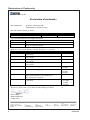
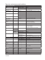
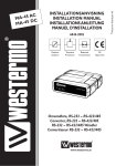
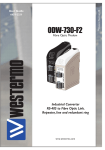
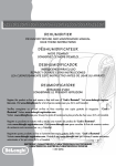
6619-2202
TDW-33
DIN-rail
Tele V.90 modem
www.westermo.com
© Westermo Teleindustri AB
User Guide Legal information
The contents of this document are provided “as is”. Except as required by applicable
law, no warranties of any kind, either express or implied, including, but not limited to,
the implied warranties of merchantability and fitness for a particular purpose, are made
in relation to the accuracy and reliability or contents of this document. Westermo
reserves the right to revise this document or withdraw it at any time without prior
notice.
Under no circumstances shall Westermo be responsible for any loss of data or income
or any special, incidental, and consequential or indirect damages howsoever caused.
More information about Westermo can be found at the following Internet address:
http://www.westermo.com
2
6619-2202
Safety
Before installation:
This modem is for restricted access area use only. Read this manual completely and gather all information on the unit. Make sure
that you understand it fully. Check that your application does not exceed the safe
operating specifications for this unit.
This unit should only be installed by qualified personnel.
This unit should be built-in to an apparatus cabinet, or similar, where access is
restricted to service personnel only.
The power supply wiring must be sufficiently fused, and if necessary it must be
possible to disconnect manually from the power supply. Ensure compliance to
national installation regulations.
Maximum 20 A branch circuit protection required.
The product is intended to work with IT power system.
This unit uses convection cooling. To avoid obstructing the airflow around the unit,
follow the spacing recommendations (see Cooling section).
Before mounting, using or removing this unit:
Prevent access to hazardous voltage by disconnecting the unit from power supply.
Warning! Do not open connected unit. Hazardous voltage may occur within this
unit when connected to power supply or TNV circuits.
Care recommendations
Follow the care recommendations below to maintain full operation of unit and to fulfil
the warranty obligations.
This unit must not be operating with removed covers or lids.
Do not attempt to disassemble the unit. There are no user serviceable parts inside.
Do not drop, knock or shake the unit, rough handling above the specification may cause
damage to internal circuit boards.
Do not use harsh chemicals, cleaning solvents or strong detergents to clean the unit.
Do not paint the unit. Paint can clog the unit and prevent proper operation.
Do not expose the unit to any kind of liquids (rain, beverages, etc). The unit is not waterproof. Keep the unit within the specified humidity levels.
Do not use or store the unit in dusty, dirty areas, connectors as well as other mechanical
part may be damaged.
If the unit is not working properly, contact the place of purchase, nearest Westermo distributor office or Westermo Tech support.
Maintenance
No maintenance is required, as long as the unit is used as intended within the specified
conditions.
The unit interior doesn’t contain any user settable items, all configuration is performed
via the DTE interface with AT-commands.
6619-2202
3
Agency approvals and standards compliance
Type
Approval / Compliance
EMC
EN 55022, Emission IT equipment
EN 55024, Immunity IT equipment
EN 61000-6-1, Immunity residential environments
EN 61000-6-2, Immunity industrial environments
EN 61000-6-3, Emission residential environments
EN 61000-6-4, Emission industrial environments
FCC part 15 Class B
EN 50121-4, Railway signalling and telecommunications apparatus
IEC 62236-4, Railway signalling and telecommunications apparatus
Safety
UL/IEC/EN 60950-1, IT equipment
PSTN
CS 03 Part 1, issue 9
FCC part 68, TIA-968-A
ETSI TS103 021-1, ETSI TS103 021-2, ETSI TS103 021-3
AS/ACIF S002, AS/ACIF S006
According to: TIA-968-A and CS-03 Part 1, issue 9
This equipment complies with Part 68 of the FCC rules and the requirements adopted by the ACTA. On the left side of this equipment is a label that contains, among other information, a product
identifier in the format US:AAAEQ##TXXXX. If requested, this number must be provided to the
telephone company.
A plug and jack used to connect this equipment to the premises wiring and telephone network must
comply with the applicable FCC Part 68 rules and requirements adopted by the ACTA. A compliant
telephone cord and modular plug is provided with this product. It is designed to be connected to a
compatible modular jack that is also compliant. See installation instructions for details.
Caution-to reduce the risk of fire, use only No.26 AWG or lager telecommunication cable.
The USOC jack required RJ11-C, and the REN is used to determine the number of devices that
may be connected to a telephone line. Excessive RENs on a telephone line may result in the
devices not ringing in response to an incoming call. In most but not all areas, the sum of RENs
should not exceed five (5.0). To be certain of the number of devices that may be connected to a
line, as determined by the total RENs, contact the local telephone company. For products approved
after July 23, 2001, the REN for this product is part of the product identifier that has the format
US:AAAEQ##TXXXX. The digits represented by ## are the REN without a decimal point (e.g., 03 is a REN of 0.3). For earlier products, the REN is separately shown on the label.
If this equipment TDW-33 causes harm to the telephone network, the telephone company will notify
you in advance that temporary discontinuance of service may be required. But if advance notice
isn't practical, the telephone company will notify the customer as soon as possible. Also, you will be
advised of your right to file a complaint with the FCC if you believe it is necessary.
The telephone company may make changes in its facilities, equipment, operations or procedures that
could affect the operation of the equipment. If this happens the telephone company will provide
advance notice in order for you to make necessary modifications to maintain uninterrupted service.
4
6619-2202
If trouble is experienced with this equipment TDW-33, for repair or warranty information, please
contact Westermo Data Communication,Inc. 11200 Westheimer,Suit 900. Houston,TX,,77042. Phone number: 713-240-0367. If the equipment is causing harm to the telephone network, the telephone company may request that you disconnect the equipment until the problem is resolved.
There are no repairs the customer/user can perform inside the modem.
In the event of equipment malfunction, all repairs should be performed by our Company or an
authorized agent. It is the responsibility of users requiring service to report the need for service to
our Company or to one of our authorized agents. Service can be facilitated through our office at:
Westermo Data Communication Inc
11200 Westheimer Suit 900
Houston,TX, 77042
TEL:713-240-0367
Connection to party line service is subject to state tariffs. Contact the state public utility commission,
public service commission or corporation commission for information.
If your home has specially wired alarm equipment connected to the telephone line, ensure the installation of this TDW-33 does not disable your alarm equipment. If you have questions about what will
disable alarm equipment, consult your telephone company or a qualified installer.
Electrical Safety Advisory:
Parties responsible for equipment requiring AC power should consider including an advisory notice
in their customer information suggesting the customer use a surge arrestor. Telephone companies
report that electrical surges, typically lightning transients, are very destructive to customer terminal
equipment connected to AC power sources. This has been identified as a major nationwide problem.
6619-2202
5
Declaration of Conformity
Westermo Teleindustri AB
Declaration of conformity
The manufacturer
Westermo Teleindustri AB
SE-640 40 Stora Sundby, Sweden
Herewith declares that the product(s)
Type of product
Model
Art no
Industrial Telephone modem
TDW-33
3619-0001
is in conformity with the following EC directive(s).
No
Short name
1999/5/EC
2011/65/EU
Radio and Telecommunication Terminal Equipment (R&TTE)
Restriction of the use of certain hazardous substances in electrical and
electronic equipment (RoHS)
References of standards applied for this EC declaration of conformity.
No
Title
Issue
EN 61000-6-1
2007
EN 55022
Electromagnetic compatibility – Immunity for residential
environments
Electromagnetic compatibility – Immunity for industrial
environments
Electromagnetic compatibility – Emission for residential
environments
Electromagnetic compatibility – Emission for industrial
environments
Information technology equipment - Emission
EN 55024
Information technology equipment - Immunity
EN 50121-4
Railway applications - Electromagnetic compatibility
Emission and immunity of the signalling and
telecommunications apparatus
Information technology equipment – Safety – General
requirements
EN 61000-6-2
EN 61000-6-3
EN 61000-6-4
EN 60950-1
The last two digits of the year in which the CE marking was affixed:
2005
2007
2007
2006
+A1:2007
1998
+A1:2001
+A2:2003
2006
2006
+ A11:2009
+ A1:2010
+ A12:2011
13
Pierre Öberg
Technical Manager
1st Mars 2013
6
Postadress/Postal address
Tel.
Telefax
Postgiro
Bankgiro
Org.nr/
Corp. identity number
Registered office
S-640 40 Stora Sundby
Sweden
016-428000
Int+46 16428000
016-428001
Int+46 16428001
52 72 79-4
5671-5550
556361-2604
Eskilstuna
6619-2202
Type tests and environmental conditions
Electromagnetic Compatibility
Phenomena
Test
ESD
EN 61000-4-2
Description
Enclosure contact
Enclosure air
Enclosure
RF field AM modulated
RF field 900 MHz
Fast transient
IEC 61000-4-3
Surge
EN 61000-4-5
RF conducted
EN 61000-4-6
Power frequency magnetic field
Pulse magnetic field
Voltage dips and interruption
EN 61000-4-8
Enclosure
Signal ports
Power ports
Signal ports unbalanced
Signal ports balanced
Power ports
Signal ports
Power ports
Enclosure
EN 61000-4-9
EN 61000-4-11
Enclosure
AC power ports
Mains freq. 50 Hz
Mains freq. 50 Hz
Voltage dips and interruption
EN 61000-4-16
SS 436 15 03
EN 61000-4-29
Signal ports
Signal ports
DC power ports
Radiated emission
Enclosure
Conducted emission
EN 55022
FCC part 15
EN 55022
FCC part 15
EN 55022
Dielectric strength
EN 60950
ENV 50204
EN 61000-4-4
Environmental
Temperature
Shock
Packaging
Enclosure
Dimension W x H x D
Weight
Degree of protection
Cooling
Mounting
6619-2202
300 A/m, 6.4 / 16 µs pulse
10 & 5 000 ms, interruption
10 & 500 ms, 30% reduction
100 & 1 000 ms, 60% reduction
100 V 50 Hz line to earth
250 V 50 Hz line to line
10 & 100 ms, interruption
10 ms, 30% reduction
10 ms, 60% reduction
+20% above & –20% below rated voltage
Class B
Class B
Class B
Class B
Class B
Class B
2 kVrms 50 Hz 1 min
3 kVrms 50 Hz 1 min
2 kVrms 50 Hz 1 min (@ rated power <60 V)
Operating
Storage & Transport
Operating
Storage & Transport
Operating
Operating
–25 to +70°C
–40 to +70°C
5 to 95% relative humidity non condensing
5 to 95% relative humidity non condensing
2 000 m / 70 kPa
IEC 60068-2-6
Operating
Operating
IEC 60068-2-27
Operating
10 year
7.5 mm, 5 – 8 Hz
2 g, 8 – 500 Hz
15 g, 11 ms
UL 94
PC / ABS
IEC 529
Enclosure
Humidity
Altitude
Reliability prediction
(MTBF)
Service life
Vibration
AC power ports
AC power ports
DC power ports
PSTN
Signal port to other
isolated ports
Power port to other
isolated ports
Test levels
± 6 kV
± 8 kV
20 V/m @ (80 – 2700) MHz 1 kHz sine, 80% AM
20 V/m pulse modulated 200 Hz, 900 ± 5 MHz
± 2 kV
± 2 kV
± 2 kV line to earth, ± 2 kV line to line
± 2 kV line to earth, ± 1 kV line to line
± 2 kV line to earth, ± 2 kV line to line
10 V 80% AM (1 kHz), 0.15 – 80 MHz
10 V 80% AM (1 kHz), 0.15 – 80 MHz
100 A/m, 50 Hz, 16.7 Hz & 0 Hz
MIL-HDBK217F
Flammability class V-1
35 x 121 x 119 mm
0.21 kg
IP 21
Convection
Horizontal on 35 mm DIN-rail
7
Description
The TDW-33 is designed to function reliably within industrial environments and in areas
of high level interference. The modem has an RS-232 interface supporting terminal data
rates up to 115 kbit/s.
The TDW-33 is a V.90 modem meaning that it can support data rates of up to 56 kbit/s
on the PSTN line side.
The modem is equipped with transient protection on the line side and a “watchdog”
that monitors and automatically resets the modem in the event of a fault. These functions together with remote configuration make the modem perfect for installation at
unmanned sites and prevent the need of costly service trips.
The modem also has password protection, dial-back security and caller ID answering to
ensure that only authorised users can communicate with the modem and any connected
equipment.
The TDW-33 is ideal for industrial applications as it mounts easily on to a 35 mm DIN-rail, runs from 12–36 Vdc power supplies, has screw terminal connections and is tri galvanically isolated.
For ease of setup the modem is supported by the Westermo TD-tool configuration software. Drivers for Windows setup are also supplied. … Extended temperature range –25°C to +70°C
… Data rate up to 56 kbit/s (V.90)
… Terminal rate up to 115.2 kbit/s
… DTR and incoming data dialling
… Watchdog
… Secure call back and access
… Industrial environment transient protection on all interfaces
… Up to 11 data bits
… Tri-Galvanic isolation (interface/line/supply)
… Caller ID presentation and answering
… Remote configuration
8
6619-2202
Interface specifications
Power LV
Rated voltage
Operating voltage
Rated current
Rated frequency
Inrush current I2t
Startup current*
Polarity
Isolation to
Connection
Connector size
Shielded cable
12 to 48 VDC or 12 to 34 VAC
10 to 60 VDC or 10 to 42 VAC
150 mA @ 12 VDC
70 mA @ 24 VDC
40 mA @ 48 VDC
150 mA @ 12 VAC
70 mA @ 24 VAC
DC: – AC: 48 – 62 Hz
0.25 A2s
0.30 Apeak
Polarity independent
All other ports 3 kVrms 50 Hz 1 min
Detachable screw terminal
0.2 – 2.5 mm2 (AWG 24-12)
Not required
* External supply current capability for proper startup
Public Switched Telephone Network (PSTN)
Electrical specification
Public Switched Telephone Network
Data rate
300 bit/s – 33.6 kbit/s
Protocol
Bell103, Bell212, V.21, V.22, V.22Bis, V.23C, V.32, V.32Bis, V.34, V.90
Protection
Installation Fault Tolerant (up to ±60 V)
Isolation to
Power port 3 kVrms 50 Hz 1 min
RS-232
2 kVrms 50 Hz 1 min
Connection
RJ-11C
Shielded cable
Not required
RS-232 Electrical specification
Data rate
Data format
Protocol
Retiming
Transmission range
Isolation to
Connection
Connector size
Shielded cable
Conductive housing
EIA/TIA-232
1 200 bit/s – 115.2 kbit/s
7 or 8 data bits, Odd, even or none parity, 1 or 2 stop bits; S 9-12 bits
Transparent
Yes
Cable length < 15 m
Power port 3 kVrms 50 Hz 1 min
RS-232
2 kVrms 50 Hz 1 min
9-pin D-sub female (DCE) and Detachable screw terminal (DCE )
Detachable screw terminal 0.2 – 2.5 mm2 (AWG 24 – 12)
Not required **
Isolated to all other circuits
** To minimise the risk of interference, a shielded cable is recommended when the cable is located inside 3 m
boundary to the rails and connected to this port. The cable shield should be properly connected (360°) to an
earthing point within 1 m from this port. This earthing point should have a low impedance connection to the
conductive enclosure of the apparatus cabinet, or similar, where the unit is built-in. This conductive enclosure
should be connected to the earthing system of an installation and may be directly connected to the protective
earth.
6619-2202
9
RS-232 (DCE)
Position
D-sub
Direction*
No. 1
No. 2
No. 3
No. 4
No. 5
No. 6
No. 7
No. 8
No. 9
Out
Out
In
In
–
Out
In
Out
Out
Position
Screw terminal*
–
No. 2
No. 1
No. 3
No. 5
No. 4
D-sub description
Description
Data Carrier Direct (DCD)
Received Data (RD)
Transmitted Data (TD)
Data Terminal Ready (DTR)
Signal Ground (SG)
Data Set Ready (DSR)
Request To Send (RTS)
Clear To Send (CTS)
Ring Indicator (RI)
Direction*
Not Connected
Out
In
In
–
Out
LED Indicators (for details see
next page)
1
2
3
4
5
6
7
8
9
Description
Data Carrier Direct (DCD)
Received Data (RD)
Transmitted Data (TD)
Data Terminal Ready (DTR)
Signal Ground (SG)
Data Set Ready (DSR)
PSTN
Position
RJ-11C
a
b
c
d
e
f
Direction*
In/Out
In/Out
Product marking PSTN
Description
Not Connected
Not Connected
PSTN Transmit/ Receive
PSTN Transmit/ Receive
Not Connected
Not Connected
Power LV
Position
No. 1
No. 2
Direction*
In
In
Description Product marking
–Voltage
+Voltage
* Direction relative this unit.
10
6619-2202
LED Indicators
LED
TD
Transmit data
RD
Receive data
RTS
Request to send
DCD
Data carrier
detect
DTR
Data terminal
ready
REL
Reliable mode
LINE
PWR
Power
6619-2202
Status
OFF
ON / FLASH
OFF
ON / FLASH
OFF
ON
OFF
ON
OFF
ON
OFF
ON
FLASH
OFF
ON
FLASH
OFF
ON
FLASH
Description
No data
The modem receiving data on the DTE interface
No data
The modem transmitting data on the DTE interface
RTS signal is inactive
RTS signal is active
DCD signal is inactive
DCD signal is active, modem has detected a carrier
or the signal is set to always ON
DTR signal is inactive
DTR signal is active
Reliable mode is OFF, direct or normal mode
Reliable mode is ON
Reliable mode with error correction and compression
The modem is on-hook
The modem is off-hook with a established connection
The modem is off-hook and negotiating
The modem has no power
The modem is up and running
The modem is in the power-on selftest
11
Mounting
This unit should be mounted on 35 mm DIN-rail, which is horizontally mounted inside an apparatus cabinet, or similar.
Snap on mounting, see figure.
CLICK!
CLICK!
Cooling
This unit uses convection cooling. To avoid obstructing the airflow around the unit, use the following spacing rules. Minimum
spacing 25 mm (1.0 inch) above /below and 10 mm (0.4 inches)
left /right the unit. Spacing is recommended for the use of unit
in full operating temperature range and service life.
10 mm * (0.4 inches)
25 mm
* Spacing (left/right) recommended for
full operating temperature range
25 mm
Removal
Press down the black support at the top of the unit. See figure.
12
6619-2202
Windows configuration tool TD-Tool
The TD-Tool is a PC – application program with a graphical interface for easy
configuration of the complex functions found on the encolsed CD or at the Westermo
website.
Please refer to TD-Tool for a complete description of the functionality of the Windows
program.
AT-Commands
Please refer to the AT Commands Interface Guide found on the enclosed CD or at
the Westermo website for a complete list of all available AT-commands and a detailed
description of the serial AT-command interface.
Configuration
The TDW-33 can be configured both from the local DTE interface and remotely over
the PSTN network. Whether the local or remote interface is used the configuration
can be made with AT-commands or with a PC-based application configuration tool. The TDW-33 can be configured from a remote modem. To configure a TDW-33 any GSM,
ISDN or PSTN modem can be used.
The modem used to configure is referred as the “local modem”.
Please make sure that the remote TDW-33 is connected to the PSTN network and is powered up.
… Connect the local modem to it's media (ISDN, PSTN or GSM)
… Connect the PC's com-port to the DTE interface of the local modem.
… Connect the power supply.
… Start a terminal emulation program (i.e. Windows Hyper-Terminal).
… Configure the local modem data rate and word format.
… Set up a connection to the remote TDW-33 to be configured by using the normal
dial command: ATD<No><CR>. When connected send the remote escape sequence
<++++>. The called remote TDW-33 will acknowledges by requesting the remote
password. Enter the correct password (default: no password, just return). Next; configure the remote TDW-33 using AT-commands. The password for remote configuration is defined with AT*WRCP – Remote configuration password.
… Configure the parameter on the remote TDW-33 from your terminal program and
save the settings with AT&W.
… Hang up the connection using the ATH command.
6619-2202
13
Application examples
… TDW-33 connected to TDW-33 with DTR signal call
PSTN Network
Configure the units
AT&F
AT&W
Set the unit to factory default
Store default settings
Set up the connection – The dialling modem
AT&Z0=nnn
AT&S0
AT&B1
AT&W
Switch DTR from
OFF to ON
Store the number of the remote modem in the dialling TDW-33
Set DSR signal always high (if this signal is used to trig the DTR)
Activates automatic DTR dialling if DTR switches from low (OFF) to high
(ON)
Save settings
The modem will now dial the phone number stored in the first location of
the telephone number table (AT&Z0=<nnn>)
Set up the connection – The answering modem
ATA
NOTE:
Enter the answer command when RING comes from the network or set up
ATS0=1 to auto answer on 1 RING signal (or more than 1)
If no valid DTR signal can be provided by external application, the modems
DSR signal can be used to trig the transmission. Connect the DSR signal via
a relay, or other potential free contact, to the DTR signal. A 10 kohm pull
down resistor should also be connected between the DTR and a signal that
is always low e.g. the DCD.
Relay
DTR
External
application
DSR
DCD
14
10 kohm
May be required in harsh environments.
6619-2202
… Frequently used settings for PLC-systems
PSTN Network
Most PLC-systems and other industrial applications where modems are used require the
same changes to the standard settings.
The most commonly encountered problems concern speed, parity and control signals
from the connected equipment.
If this action does not solve the problem the modem’s answering codes and possible
echoing of commands might be the source of the difficulty.
Below follows a list of commands that might resolve the problems. The commands may
of course be placed on one single command line if desired.
Configure the TDW-33 connected to the PLC
AT&F
ATV0
ATQ1
ATE0
AT&C1
AT&K0
AT&A1
AT&W
6619-2202
Set the unit to factory default.
Gives the answering codes in short format. (digits)
No result codes are sent on the RS-232/V.24 connection.
Commands that are sent from the terminal/computer etc. are not echoed
back to the RS-232/V.24 connection.
DCD will follow the carrier on the line.
No hand shaking.
Character abort option on.
Store default settings.
15
… TDW-33 – Secure Call-back
The TDW-33 is connected to a PLC which one want to restrict access to. The TDW-33
can support access control through the Secure Callback function. In this example password and callback to a predefined number is chosen. The modem in the calling end is
here chosen to be a PSTN modem, but can be any of the PSTN, ISDN or GSM modem
from the Westermo product range.
The DTE serial speed between the PLC – TDW-33 and TD-36 – PC is assumed to be
9600 8N1 but can be chosen to fit the actual system requirement.
PSTN Network
Configure the TDW-33
AT&F
AT+IPR=9600
AT+ICF=3,4
ATS0=1
ATQ1E0&C1&K0&A1
AT&W
AT*WCB=4
AT*WCBTAB=1,”+4670428000”,
”n3Y9kA6otYZu8”
AT*WCBTIME=10
16
Set the unit to factory default
DTE baudrate 9600
Character framing 8 data, 1 stop, parity none
Auto answer after first ring
Suitable for PLC communication
Store default settings
Callback enabled, Password and callback number stored in one or more positions of wcbtab
Define callback number 1
When password 1 is entered number +4670428000 will be
called
Define delay time between hangup and callback The TD-36 will wait 10 s after hangup to callback to allow the analogue modem to hangup
6619-2202
Configure the TD-36
AT&F
AT+IPR=9600
AT+ICF=3,4
ATS0=1
AT&W
Set the unit to factory default
DTE baudrate 9600
Character framing 8 data, 1 stop, parity none
Auto answer after first ring
Store default settings
Set up the connection
The dialling modem
TD-36
ATD0705123456
NO CARRIER
The answering modem
TDW-33
TDW-33 answers the call and
requests to TDW-33
TDW-33 verifies the password
to the passwords stored and if
true compare dissconnects.
Wait 10s
CONNECT 9600
TDW-33 dials +4670428000
CONNECT 9600
CONNECT 9600
6619-2202
Comment
Dial the number to TDW-33
Operator/system at TD-36 enters Password: n3Y9kA6otYZu8
The connection is broken and TDW-33
waits the programmed 10s for TDW-33
to disconnect
The number programmed corresponding to the password is dialled, preferable it’s the number to the TD-36
Connection is established between the
PC at TD-36 and the PLC at TDW-33
17
… TDW-33 – Silent answering on predefined number
The TDW-33 is connected to a power meter which is remotely monitored. The TDW-33
shares the PSTN line with normal telephones which is preferred not to give a ring signal
when the meter is read.
The TDW-33 is configured to answer calls on the Caller ID received, the valid numbers
to answer is programmed into the TDW-33. There exists a number of standards for sending Caller ID check which standard is used by your operator. The TDW-33 supports the
major implementations of Caller ID. In this example the DTMF Caller ID version is used. Note that some implementations doesn’t give the possibility to make a silent answer
since the Caller ID is sent between first and second ring signal.
The modem in the calling end is here chosen to be a PSTN modem, but can be any of
the PSTN, ISDN or GSM modem from Westermo product range.
PSTN Network
Configure the TDW-33 connected to the power meter
AT&F
AT+IPR=9600
AT+ICF=3,4
ATS0=0
ATQ1E0&C1&K0&A1
AT&W
AT*WACCTAB=1,”016428000”
AT*WACCTAB=2,”016480250”
AT*WCID=3,3
18
Set the unit to factory default
DTE baudrate 9600
Character framing 8 data, 1 stop, parity none
No auto answer on Ring signals
Suitable for PLC communication
Save settings
Set the valid A-numbers for automatic answering
Set Caller ID to A-number answer with DTMF coded numbers
6619-2202
Westermo • SE-640 40 Stora Sundby, Sweden
Tel +46 16 42 80 00 Fax +46 16 42 80 01 E-mail: [email protected] www.westermo.com
United Kingdom
Westermo Data Communications Talisman Business Centre Duncan Road, Park Gate, Southampton. SO31 7GA Tel: +44 (0) 1489 580 585 • Fax: +44 (0) 1489 580 586 [email protected] • www.westermo.co.uk
Germany
Westermo Data Communications Goethe Strasse 67 DE-68753 Waghäusel Tel: +49 (0) 7254 95400-0 • Fax: +49 (0) 7254-95400-9 [email protected] • www.westermo.de
Austria
Westermo Data Communications Tel: +43 (0) 72030 3920 • Fax: +43 (0) 2235 86131 [email protected] • www.westermo.at
France
Westermo Data Communications Bat. A, 9 Chemin de Chilly FR-91160 Champlan Tel: +33 1 69 10 21 00 • Fax: +33 1 69 10 21 01 [email protected] • www.westermo.fr
North America
Westermo Data Communications 939 N. Plum Grove Road, Suite F, IL 60173 Schaumburg, USA Tel: +1 847 619 6068 • Fax: +1 847 619 66 74 [email protected] • www.westermo.com
Singapore
Westermo Data Communications 84 Genting Lane #07-03 Cityneon Design Centre Singapore 349584 Tel: +65 6743 9801 • Fax: +65 6745 0670 [email protected] • www.westermo.com
Malaysia
Westermo Data Communications 84 Genting Lane #07-03, Cityneon Design Centre, Singapore 349584 Tel : +6 012 2781156 • Fax : +603 8062 7467 [email protected] • www.westermo.com.sg
China
Westermo Data Communications 2F Building B No.1618 Yishan Road Shanghai 201103 Tel: +86 21 6145 0400 • Fax: +86 21 6145 0499 [email protected] • www.cn.westermo.com
Westermo Teleindustri AB have distributors in several countries, contact us for further information.
REV.D 6619-2202 2013-03 Westermo Teleindustri AB, Sweden – A Beijer Electronics Group Company
Sales Units
Sweden
Westermo Data Communications Svalgången 1, Vallbyinstitutet, 724 81 Västerås Tel: +46 (0) 21 548 08 00 • Fax: (0) 21 35 18 50 [email protected] • www.westermo.se