1
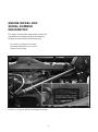
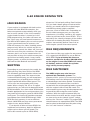
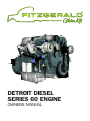
DETROIT DIESEL
SERIES 60 ENGINE
OWNERS MANUAL
CONTACT
FITZGERALD GLIDER KITS
1225 Livingston Hwy
Byrdstown, TN 38549
Monday–Friday, 8am–5pm (CST)
Toll Free: (888) 649-1053
Sales: (931) 864-4885
Warranty: (931) 864-4886
FAX: (931) 864-4895
www.fitzgeraldgliderkits.com
ENGINE MODEL AND
SERIAL NUMBER
DESIGNATION
The engine serial number and model number are
stamped on the cylinder block in the following
location (as viewed from the flywheel end):
Left side just below the intake manifold and above the cast-in
Detroit Diesel logo.
Location of Engine Serial and Model Numbers
1
DDEC II
NOTICE:
Detroit Diesel Series 60 engines equipped
with DDEC II electronic control systems are
identified by a “U” in the sixth position of the
model number. Example: 6067GU60.
Detroit Diesel Electronic Controlled Series
60 engines can be equipped with a variety of
options designed to warn the operator of an
engine malfunction. The options can range
from “Check Engine” and “Stop Engine” panel
lights to automatic reduction in engine power
followed by automatic engine shutdown.
The power-down/shutdown option may be
activated by low coolant level, low oil pressure,
or high engine oil or coolant temperature.
If the warning lights stay on, or if they
do not come on momentarily after
turning on the ignition, consult with a
DDEC technician. Operating the engine
under these circumstances may result
in engine damage.
The Series 60 DDEC engine is equipped
with an electronically controlled fuel
injection system. There are no control racks
or mechanical linkage to adjust. This system
not only helps to improve fuel economy
and vehicle performance, but also helps
to reduce cold starting time and increase
initial idle speed for fast engine warm-up and
DDEC III/IV
virtual elimination of cold smoke.
The DDEC engine has no mechanical
Detroit Diesel Series 60 engines equipped with
governor. Engine horsepower, torque, idle,
DDEC III or DDEC IV electronic control systems
and engine speed are contained in the
are identified by a “K” in the sixth position of
internal electronics. Therefore, there are no
the model number. Example: 6067GK60.
mechanical governor spring adjustments for
Detroit Diesel Electronic Controlled Series
idle and high speed control.
60 engines can be equipped with a variety of
There is no need for a throttle delay
options designed to warn the operator of an
either, since emission control is performed
engine malfunction. The options can range
through the Electronic Control Module (ECM).
from “Check Engine” and “Stop Engine” panel
The Electronic Foot Pedal Assembly (EFPA),
lights to automatic reduction in engine power
eliminates the need for any throttle linkage.
followed by automatic engine shutdown.
The DDEC engine has the ability to
The power-down/shutdown option may be
perform diagnostics for self-checks and
activated by low coolant level, low oil pressure,
continuous monitoring of other system
or high engine oil or coolant temperature.
components. Depending on the application,
DDEC can also monitor oil temperature,
coolant temperature, oil pressure, fuel
pressure, coolant level, and remote sensors
(if used). This diagnostic system is connected
to the “Check Engine” light (CEL) and the
“Stop Engine” light (SEL) to provide a visual
warning of a system malfunction.
Typical Shut-Down Override Switch and
Engine Lights
2
DDEC III/IV ENGINE
PROTECTION
The immediate speed reduction option will
bring engine RPM back to a predetermined
speed, but will not shut down the engine.
The engine should not be restarted after it
has been shut down by the engine protection
system unless the problem has been located
and corrected.
The conditions that will cause the “Stop
Engine” light to come on are:
Since many vehicles are equipped with the
DDEC engine protection system, the “Stop
Engine” malfunction is recorded in the
Electronic Control Module. With the 30
second shutdown option, the engine will
begin a 30 second stepped power down
sequence until it shuts down completely.
To allow for the possibility of the “Stop
Engine” automatic shutdown function being
activated while the vehicle is operating in a
critical situation, an override is provided.
In such a situation the operator may elect
to “override” the automatic stop engine
sequence by pressing the “Stop Engine
Override” switch, located on the instrument
panel, until a safe stop can be made. The
operator only needs to press the override
switch every 15 to 20 seconds to prevent the
engine shutdown from occurring.
An important thing to remember is that
it takes 30 seconds from the time the
automatic shutdown sequence begins until
engine shutdown. Therefore the operator
must press the override switch just prior to
engine shutdown and continue to do so until
the vehicle can be brought to a safe stop.
■ Loss of coolant
■ High oil temperature
■ Low oil pressure
■ Auxiliary shutdown
It is important to point out that whenever the
CEL or the SEL comes on, the DDEC computer
will determine where the problem is, and will
then store this information in its memory.
If the malfunction is intermittent, the lights
will come on and go off as the computer
senses the changing engine condition.
A special diagnostics tool (Diagnostics
Data Reader, or “DDR”) is available that
can be plugged into the engine computer
memory to extract information related to the
cause of the problem.
3
EMERGENCY JUMP
STARTING
Once the malfunction has been corrected,
the DDEC system will return the engine to
normal operation.
The DDR can distinguish between
codes now active and those stored in the
historic code memory.
The malfunction code recorded in the
computer memory will remain until it is
erased by a technician.
The malfunction code can also be
obtained by the operator. A “Diagnostic
Request” switch may be provided which,
when pressed, will cause the CEL to flash a
code number. It will, for example, flash twice
… pause … flash five times … pause. In other
words a code 25.
Code 25 will continue to flash and repeat
as long as the check engine switch is held
in the “On” position with the ignition on.
The DDEC II electronic control system operates
on 12 volt DC. If a DDEC II engine with an
electronic starting motor requires emergency
jump starting, do not exceed 16 volts DC.
DDEC III and DDEC IV electronic control
systems operate on 12 or 24 volts DC. If a
DDEC III or DDEC IV engine with an electronic
starting motor requires emergency jump
starting do not exceed 32 volts DC.
NOTICE:
Jump starting with voltages greater
than those indicated or reversing
battery polarity may damage the ECM
(Electronic Control Module).
4
DDEC II Diagnostic Codes
Diagnostic Connector
TO READ CODES: Use diagnostic data
reader or short pin A to pin M. The latter
method will flash codes at the CEL.
Error
Code #
11
12
13
14
15
16
21
22
23
24
25
26
31
32
33
34
35
36
37 38
41
Error
Code #
42
43
44
45
46
47
48
51
52
53
54
55
56
58
61-68
71-78
84
85
86
87
Description
Power Take-off Sensor Lo Volt
Power Take-off Sensor Hi Volt
Coolant Sensor Lo Volt
Eng Temp Sensor Hi Volt
Eng Temp Sensor Lo Volt
Coolant Sensor Hi Volt
Throttle Pos Sensor Hi Volt
Throttle Pos Sensor Lo Volt
Fuel Temp Sensor Hi Volt
Fuel Temp Sensor Lo Volt
No Codes
Power Control Enabled
Fault on Auxiliary Output
ECM Backup System Fail
Turbo Bst Sensor Hi Volt
Turbo Bst Sensor Lo Volt
Oil Prs Sensor Hi Volt
Oil Prs Sensor Lo Volt
Fuel Prs Sensor Hi Volt
Fuel Prs Sensor Lo Volt
Timing Reference Sensor
Description
Synchronous Ref Sensor
Low Coolant Level
Engine Over Temperature
Low Oil Pressure
Low Battery Voltage
Hi Fuel Pressure
Lo Fuel Pressure
EEPROM Error
ECM - A/D Fail
EEPROM Memory Failure
Vehicle Speed Sensor
Proprietary Comm. Link
ECM - A/D Fail
Cruise Ctl/Press Gov Ctl Switch
Inj Response Time Long
Inj Response Time Short
Crankcase Pressure Hi
Engine Overspeed
Press Gov Ctl - Hi Volt
Press Gov Ctl - Lo Volt
CEL Examples
CEL
1 Flash
CEL
3 Flashes
Short Pause
2 Flashes
Long Pause
Code 13
1 Flash
Short Pause
Code 21
NOTE: The CEL flashing gives both active and inactive (historic) codes.
5
DDEC III/IV Diagnostic Codes
Flash
Code
11
12
13
14
15
16
17
18
21
22
23
24
25
26
27
28
31
32
33
34
35
36
37
38
41
42
43
Flash
Code
44
45
46
47
48
52
53
54
55
56
57
61
62
63
64
65
66
67
68
71
72
73
74
75
76
77
85
86
87
DDEC III/IV Description
VSG Sensor Input Voltage Low
VSG Sensor Input Voltage High
Coolant Level Sensor Input Voltage Low
Oil or Coolant Temp. Sensor Input Voltage High
Oil or Coolant Temp. Sensor Input Voltage Low
Coolant Level Sensor Input
Voltage High
Throttle Valve Position Sensor Input
Voltage High
Throttle Valve Position Sensor Input
Voltage Low
TPS Input Voltage High
TPS Input Voltage Low
Fuel Temp. Sensor Input Voltage High
Fuel Temp. Sensor Input Voltage Low
No Active Codes
Aux. Engine Shutdown #1 or #2,
Input Active
Air Inlet or Intake Air, Temp. Sensor
Input Voltage High
Air Inlet or Intake Air, Temp. Sensor
Input Voltage Low
Aux. High Side Output Open Circuit or
Short to Ground
CEL or SEL Short to Battery (+) or
Open Circuit
Turbo Boost Sensor Input Voltage High
Turbo Boost Sensor Input Voltage Low
Oil Pressure Sensor Input Voltage High
Oil Pressure Sensor Input Voltage Low
Fuel Pressure Sensor Input
Voltage High
Fuel Pressure Sensor Input Voltage Low
Too Many SRS (Missing TRS)
Too Few SRS (Missing SRS)
Coolant Level Low
DDEC III/IV Description
Oil or Coolant or Intake Air, Temp. High
Oil Pressure Low
ECM Battery Voltage Low
Fuel, Air Inlet, or Turbo Boost
Pressure High
Fuel or Air Inlet Pressure Low
ECM A/D Conversion Fail
ECM Non Volatile Memory Fault
Vehicle Speed Sensor Fault
J1939 Data Link Fault
J1587 Data Link Fault
J1922 Data Link Fault
Injector Response Time Long
Aux. Output Short To Battery (+) or
Open Circuit, or Mech. Fault
PWM Drive Short to Battery (+) or
Open Circuit
Turbo Speed Sensor Input Fault
Throttle Valve Position Input Fault
Engine Knock Sensor Input Fault
Air Inlet Pressure Sensor Input
Voltage Fault
TPS Idle Validation Switch Open Circuit
or Short to Ground
Injector Response Time Short
Vehicle Overspeed
Gas Valve Position Input Fault or
ESS Fault
Optimized Idle® Safety Loop Short
to Ground
ECM Battery Voltage High
Engine Overspeed with Engine Brake
Fuel Temperature High
Engine Overspeed
External Pump Pressure Sensor Input
Voltage High
External Pump Pressure Sensor Input
Voltage Low
TO READ CODES: Use the diagnostic data reader or depress and hold the diagnostic
request switch with the ignition on, engine at idle or not running. Press and hold the switch.
Active codes will be flashed on the “Stop Engine” light (SEL) followed by the inactive codes
being flashed on the “Check Engine” Light (CEL). The cycle will repeat until the operator
releases the diagnostic request switch.
6
S-60 ENGINE DRIVING TIPS
ACCELERATING THE
VEHICLE
The cruise light will come on. To increase
road speed in one MPH increments, press
the resume/accel switch. To reduce speed,
press and hold the set/coast switch until
the lower speed is reached. Cruise control
is deactivated by slightly depressing the
service brake, clutch pedal, or trailer brake.
Also, the on/off switch deactivates cruise
control. Cruise control will maintain speed
even on upgrades, unless power requirements
demand a downshift. And, of course, cruise
control doesn’t limit your speed on downgrades.
Most likely, the cruise control will feel stronger
than driving with the foot pedal because of
the instantaneous and wide open throttle
response. That is why cruise control is not
suggested during slippery conditions.
Use cruise control after downshifting on a hill
to pull the hill. Hitting the resume switch (not
the set switch) will keep the truck accelerating
in the lower gears up to rated engine speed.
Cruise control will disengage below 1100
RPM or 20 MPH road speed. If you want
to pull the engine below 1100 RPM when
using cruise control, remember to hold the
throttle pedal to the floor to keep the engine
pulling at wide open throttle. Realistically,
the engine will pull to about 1050 RPM.
Remember: the electronic data programmed
into the ECM will not allow you to hurt or overfuel the engine at low or lug speeds. There is
enough oil pressure to withstand hard pulls
at low engine speeds.
Engine response versus pedal movement
may feel different from the mechanical
governed engine you were driving. The
electronic foot pedal assembly was designed
to communicate “percentage” foot pedal
travel to the engine’s electronic control
module. The engine will respond accordingly
to the driver’s demand.
Another throttle or governor characteristic
you may need some time to get used to the
DDEC limiting speed governor. This allows
the driver to command total engine response
between idle and rated speed, such as
accelerating at half throttle—an advantage
when driving under slippery conditions.
If you do require wide open throttle engine
response, either accelerating or just plain
pulling hard, the throttle will have to be
held to the floor. To obtain 100% fueling at
any speed, the foot pedal will have to be
maintained at the fully depressed position.
CRUISE CONTROL
For added driver convenience and comfort,
DDEC III also features a cruise control option
which works just like the system in your
car. It can be operated in any gear above
1100 RPM or road speed faster than 20
MPH, up to the rated engine speed. It can
be programmed to hold your road speed at
or below the maximum vehicle speed. The
switch to energize cruise control is usually
mounted on the instrument panel. Turn the
switch to the on position to energize the
system. When you reach road speed, press
the set switch to activate cruise control.
7
S-60 ENGINE DRIVING TIPS
JAKE BRAKES
almost as if it had quit pulling. Don’t believe
it! if you had a boost gauge to look at while
driving, you would notice the turbocharger
maintaining steady intake manifold
pressure, even as RPM’s fall. Depending on
the air intake arrangement, you may also
experience a “chuffing” sound as the engine
starts to pull hard at the lower RPM’s. This is
caused by the velocity changes of the airflow
within the air intake plumbing. Electronic
engines can actually deliver more fuel at
lower engine speeds than rated speed.
If your engine is equipped with both cruise
control and Jake Brake® retarders, the
Jakes can operate automatically while you
are in cruise control. If the cruise control/
engine brake function is turned on in the
ECM programming, the Jakes will come on
“low” when your set road speed increases a
few MPH or KPH above your set cruise speed.
If your speed continues to increase, the
ECM will increase the Jakes’ braking power
progressively. When the vehicle returns to
the set cruise speed, the Jakes will “turn off”
until the next time you need them. For safety
reasons, don’t use cruise control when it’s
not possible to keep the vehicle at constant
speed due to winding roads, heavy traffic,
slippery roads, or when descending grades
that call for Jake Brake® assistance.
IDLE REQUIREMENTS
If you have to idle your engine for any reason,
it is suggested that RPM’s be set at 900 to
1000 RPM. Try to minimize idle times as
much as possible for the first 10,000 miles
on the engine. Lower idle RPM’s will cause
oil slubber, and can inhibit the cylinder
rings’ ability to seat properly.
SHIFTING
IDLE SHUTDOWN
Depending on your transmission model, the
gear split may vary from 500 to 300 RPM.
The electronic governor provides almost no
overrun capability, and if the transmission
is downshifted too early, you will experience
a temporary loss of pulling power until the
engine speed falls below rated speed. This
is true even on steep grades with heavy
loads. When using an 18, 15 or 13 speed
transmission, you will need to downshift at an
RPM that allows “less than rated” RPM before
throttle application in the next gear down. You
may want to limit engine speed to 1900 RPM
in all gears. The Series 60 provides constant
horsepower from 1800 RPM through 2100
RPM, but fuel economy is not as efficient
above 1800 RPM and may cause premature
engine issues and/or failures.
If you decide to drive at lower RPM’s for
improved fuel economy, don’t let different
engine noises throw you off guard. The
Series 60 sounds quiet at 1400 RPM,
The DDEC engine may also have an
optional idle shutdown system. The
purpose of this system is to conserve fuel by
eliminating excessive idling and to allow for
a turbocharger cool down period. To activate
the shutdown, the transmission must be in
neutral with the vehicle parking brakes set and
with the engine in idle or fast idle mode. The
cruise control system may also be programmed
to permit fast idle using the cruise control
switches. With the engine at normal idle, the
transmission in neutral, and the service brake
on, turn on the cruise control “on/off” switch,
and use the “Resume” switch. The engine RPM
should increase to a predefined RPM. The RPM
can be raised or lowered from this point using
the “set” and “resume” switches.
8
FITZGERALD WARRANTY STATEMENT
Fitzgerald Glider Kits is not responsible for the cost of maintenance or repairs due to lack of
performance of required maintenance services or the failure to use Fuel, Oil, Lubricants, and
coolants meeting Detroit Diesel recommended specifications. Performance of said required
maintenance and use of proper fuel, oil, lubricants and coolants are the responsibility of the owner.
CODES: I–Inspect, Service, Correct
or Replace as Necessary.
R–Replace
9
LUBRICANT SELECTION IN
NORTH AMERICA
LUBRICANT
REQUIREMENTS
The selection of the proper lubricating
oil is important to achieve the long and
trouble-free service which Detroit Diesel
engines are designed to provide. The proper
lubricating oil for all Detroit Diesel engines is
selected based on SAE viscosity grade and
API (American Petroleum Institute) service
designation. Only oils licensed to display the
American Petroleum Institute (API) symbol
shown should be used.
Lubricants meeting these criteria have
provided maximum engine life when used in
conjunction with specified oil drain and filter
maintenance schedules.
SAE Viscosity Grade: 15W-40
API Classification: CH-4–CJ-4
HT/HS Viscosity: 3.7 cP minimum
The preferred lubricating oil is
Shell Rotella SAE 15W-40 (CJ-4).
(P/N 23512703)
API Lubricant Service Mark
SYNTHETIC OIL
OIL DRAIN INTERVALS
Synthetic oils may be used in Detroit Diesel
engines, provided they are approved by a
Power Guard Oil Specification. The use of
synthetic oil does not necessarily ensure
the extension of the recommended oil drain
interval beyond its limits.
During use, engine lubricating oil undergoes
deterioration from combustion byproducts
and contamination by the engine. In addition,
certain components in a lubricant additive
package are designed to deplete with use. For
these reasons, regardless of the oil formulation,
regular oil drain intervals are required.
Fitzgerald Glider Kits recommends first initial oil
change at 5,000 to 7,000 miles to remove breakin metals and rebuild contaminates. Oil should be
changed every 15,000 miles thereafter.
10
LUBRICATING OIL CHECKS
NOTICE:
Check the oil level daily with the engine
stopped. If the engine has just been stopped
and is warm, wait approximately 20 minutes
to allow the oil to drain back to the oil pan
before checking. Add the proper grade of oil
to maintain the correct level on the dipstick.
Do not overfill. Oil may be blown out
through the crankcase breather if the
crankcase is overfilled
COOLANT
Check Oil Level Daily
All diesel engines are designed to use some
oil, so the periodic addition of oil is normal.
See “Engine Oil Consumption Guidelines” to
determine the degree of oil usage.
Shell Rotella ELC Engine Coolant is the
preferred ethylene glycol coolant. If other
commercial brands of ethylene glycol are used,
they must be equivalent to the Shell Rotella ELC.
ENGINE OIL CONSUMPTION
GUIDELINES
*SERVICE IS
RECOMMENDED
HIGH
SLIGHTLY
HIGH
NORMAL
MILES PER QUART
Kilometers = miles x 1.6. For off-highway applications, 1 hour = 33 miles.
*Have your engine serviced by an authorized Detroit Diesel service facility at the earliest opportunity.
Conventional Coolant (commonly green)
Test at every service using Pencool or Power Cool test strips.
Any additive supplements should be Power Cool or Pencool.
Fully Formulated (commonly red or purple)
Test at every service. Repeat steps mentioned above.
Extended Life Coolant (commonly red or pink)
Check freeze point at every service. Requires an enhancer at 325,000 miles.
Refer to decal on coolant reservoir.
11
LOW
SUPPLEMENTAL COOLANT
ADDITIVE (SCA) TEST
PROCEDURES
Wait at least 60, but no longer than 75,
seconds before reading the nitrite level.
Promptly replace and tighten the test strip
container cap after each use. Discard unused
strips if they have turned light pink or tan.
A factory analysis program is available
through authorized Detroit Diesel service
outlets. To verify coolant acceptability, submit
a sample for coolant analysis every three
(3) years, 300,000 miles, (480,000 km), or
6,000 operating hours, whichever comes first.
If any other coolant additive is used, follow
that particular manufacterers guidlines.
Pencool 3-Way Coolant Test Strips should
be used to measure nitrite and glycol
concentrations. Cavitation/corrosion
protection is indicated on the strip by the
level of nitrite concentration. Freeze/boilover protection is determined by glycol
concentration. Use the test strips as follows:
1. Dip the strip into coolant for one second.
Remove and shake briskly to eliminate excess fluid.
NEED RELEASE COOLANT
FILTERS
2. Immediately compare end pad(% Glycol) to
the color chart on the container.
3. Sixty seconds (one minute) after dipping,
compare the nitrite pad to the color chart.
Spin-on coolant filters are available for Detroit
Diesel engines. Membranes in the filters
release SCAs before the coolant approaches
a corrosive condition, protecting the engine
from corrosion. The elements release the
SCA charge as needed, as opposed to
the maintenance SCA elements, which
instantaneously release the SCA charge.
These elements should be replaced after 1
year, 120,000 miles, (192,000 km), or 2,000
operating hours, whichever comes first.
4. Color change of additive indicator (middle
pad) indicates presence of inhibitor that is not
approved by Detroit Diesel.
For best results make the tests while the
coolant is between 50ºF–120ºF (10.ºC–60ºC).
12
FUEL PROCESSORS
DIESEL FUEL
Many vehicles are now equipped with
optional fuel processors, such as Detroit
Diesel’s Fuel Pro 382. This single filter
system replaces traditional primary and
secondary filters. By reducing the number
of filters and extending the change interval,
filter expense can be reduced by up to 75%.
The quality of fuel used in the Detroit Diesel
engine is a very important factor in obtaining
satisfactory engine performance, long
engine life and long injector life. Biodiesel
fuels can decrease the life of fuel filters
and degrade their water coalescing ability.
Failures attributed to the use of fuels which
do not meet industry standards are not the
fault of Fitzgerald Glider Kits, and will not be
covered by Fitzgerald Glider Kits warranty.
Fitzgerald Glider Kits recommends using a
7 to 10 micron filter. Using a 7 micron filter
will increase filter change frequency, but will
provide better protection for the injectors
Here is how the Fuel Pro 382 works:
Clean
50%
75%
100%
3. Restriction remains consistently low. Even
though the fuel level is now over more than
half of the element, the fuel is still flowing
through clean new media.
1. When new, the fuel level in the 382 filter
will be very low. The filter is causing minimal
restriction. as the filter used in Model 382, dirt
collects on the filter from the bottom up. Fuel
rises on the filter indicating remaining filter life.
4. The filter element is now covered by fuel,
and it is using all of the media’s surface
area. Restriction is just starting to rise and
the element should be changed at the next
scheduled maintenance interval.
2. Fuel level remains low. As dirt is trapped on the
filter, the fuel rises over the dirt and flows through
clean filter media to keep flow restriction low.
NOTE: If your vehicle is not equipped with a Fuel
Pro, retrofit kits are available from DDC outlets.
13
AFTERMARKET FILTRATION PARTS LIST FOR OUR
SYSTEMS
6067GK60 MODEL
ENGINES ONLY
Aftermarket Fuel supplemental filtration
systems may be used, provided they do
not replace the factory installed system,
reduce fuel volumes, pressures, or flow rates
delivered to the engine.
ADDITIONAL
MAINTENANCE ITEMS:
Detroit Fuel Filter
23538657
Luber Finer Oil Filter
LFP2160
Borg Warner Turbo
171702
Water Pump
R23522707
InjectorsR23555915
Transmission: 50wt synthetic oil drain/flush
at 500,000 miles
Differential: 75w90 synthetic oil drain/flush
at 500,000 miles
Power Steering filter change interval:
Once a year.
Service Eaton “Easy Pedal” clutches based
on manufacturers recommendations.
Cam Sensor
8929387
Crank Sensor
8929388
Oil Pressure Sensor
23532797
7 Micron Filter
23521528
10 Micron Filter
23533816
Other engine model componants will vary.
(6067WK60, 6067BK60).
*Freightliner Cascadia’s use “solo” clutches.
Follow manufacturers recommendations.
OVERHEAD SETTINGS
If your suspension does not have grease
fittings, it is a sealed, maintenance free
system. Contact manufacturers
for recommendations.
As previously stated, Fitzgerald Glider kits
recommends that the overhead be run at
60,000 miles to ensure peak performance
out of your 12.7 litre Detroit Diesel engine.
Our overhead settings are as follows:
Fitzgerald Glider Kits does not align front
ends or balance tires. This will be the
owners responsibility.
Fitzgerald Glider Kits reserves the right
to ship parts to customers or repair shop.
Certain parts are specific to our engines
and not readily available at most shops. Any
parts shipped that require special paint
colors will delay shipping.
14
Intake:
8
Exhaust:
26
Jake:
26
Injector:
80.3mm
FITZGERALD GLIDER KITS
WARRANTY INFORMATION
Do Not Perform Repairs On This Vehicle
Until Making Contact With Our Warranty
Department.” It also includes our phone
number, displayed for contact. You may
instruct the shop before hand of this, and
expedite this process somewhat if you
choose. Not following this procedure may
jeopardize your warranty availability and
increase your out-of-pocket expense. We will
give the shop permission to now diagnose
your problem, and in turn give us an estimate
for parts and labor of the repair. After we
receive this estimate, we will review it and
make sure labor times are within Motor
Manual SRT Guidelines. We will also evaluate
the parts required to determine if the parts
are something that can be purchased there,
or if they need to be shipped from our facility.
Our department staff will stay in close
contact with the repair shop throughout
the repair process, and will give you, the
customer, updates as often as you request.
As a customer of Fitzgerald Glider Kits, we
would like to take a moment to explain and
make you familiar with our warranty process.
We will break this down in 5 steps.
Step 1. Contact
We may be contacted at 866-597-3836
or 931-864-4886, Monday through Friday
from 8:00am to 5:00pm CST. After hours we
may be reached at 931-337-5794, Monday
through Friday from 5:00pm to 8:00pm CST,
and Saturday from 8:00 to 12:00pm CST.
Step 2. Repair facility
When a problem does arise with your Glider,
please contact this warranty department first.
This will allow our involvement and guidance
from the beginning, which will make for a
more pleasant experience for us all during
this process. Fitzgerald Glider Kits warranty
department would like to remind you, that
while every effort will be made by our staff to
see that your truck is repaired correctly and
in a timely manner, we are not a breakdown
service. Upon receiving your call, we will assess
the issue, and guide you towards a facility to
make the necessary repair. Due to certain
parts specific warranty policies, (such as; OEM,
Eaton, Bendix, Etc.), some repairs must be
made at the facilities that can file warranties
through these companies. Otherwise, the
warranty for repairs will not be available, and
will result in out-of-pocket expenses. Our
department will guide you in this process and
make you aware of their locations.
Step 4. Billing
After the repair is completed, Fitzgerald Glider
Kits will pay the final invoice for all agreed
upon warranty items from the estimate.
Step 5. Completion
Now that the repair has been completed and
the invoice is paid, you can get your truck
back into service, which is WHY you made
the purchase in the first place. This will be
the process that you will use any time there
is a warranty issue. Please feel free to call our
warranty department with any questions you
may have about your truck warranty. We are
here to help you make your experience with our
warranty as pleasant as possible, and to keep
your truck in service and remain profitable.
Step 3. Repairs
NOTE: Custom painted engine parts will require
and extra day of shipping due to painting.
After you have contacted us and now have
your truck at a repair shop, it is time for the
repair. The shop will notice a distinctive decal
on your engine valve cover. It says “STOP!
15
YOUR FITZGERALD GLIDER
KIT WITH DETROIT SERIES
60 ENGINE
When your Fitzgerald Glider Kit leaves our
factory floor it is filled with the following fluids:
Shell Rotella SAE 15W-40 (CJ-4) motor oil
Peak windshield washer fluid
Shell Spirax S6 GME 50wt. synthetic
transmission oil
Syngard 75w90wt. synthetic differential oil
Antifreeze: Shell Rotella ELC 50/50 Antifreeze
16
NOTES:
NOTES:
NOTES:
NOTES:
DETROIT DIESEL
SERIES 60 ENGINE